
(完整版)4×660MW电厂空气预热器培训课件
- 格式:ppt
- 大小:17.77 MB
- 文档页数:36


第十章空气预热器检修1 概述空气预热器是利用锅炉排放的烟气热量来加热燃烧所需空气的热交换设备。
由于它工作在烟气温度最低的区域,回收了烟气热量,降低了排烟温度,因而提高了锅炉效率。
同时,由于燃烧所需空气温度的提高,有利于燃料的着火和燃烧,减少了燃料不完全燃烧的热损失。
按照换热方式可将空气预热器分为两大类:传热式和蓄热式(或称再生式)。
在传热式空气预热器中,热量是连续的通过传热面由烟气传给空气的,且烟气和空气各有自己的通道;在蓄热式空气预热器中,烟气和空气交替的通过受热面。
当烟气流过受热面时,热量由烟气传给受热面金属,并被金属蓄积起来。
然后空气通过受热面,金属再将蓄积的热量传空气。
依靠这样连续不断的循环来加热空气。
现代电厂锅炉中,最常用的传热式空气预热器是管式空气预热器,最常用的蓄热式空气预热器是回转式空气预热器。
2 技术规范2.2 预热器简介2.2.1 原理简介:燕山湖发电厂2×600MW机组锅炉配两台三分仓容克式空气预热器,由哈尔滨锅炉厂自80年代引进美国ABB—AIP公司技术设计制造的,其型号为32.5-VI(T)-1933-SMR,型式为三分仓、受热面回转。
在转子径向圆周面上,烟气占有50%的流通面积,一、二次风各占其余流通面积的1/3和2/3。
由于该炉燃用褐煤,水分含量在20%以上,故转子转向采用先加热一次风后再加热二次风的转动顺序,以满足制粉系统干燥出力的要求。
当转子(受热面)转到烟气流通区域时,烟气自上而下流过受热面,受热面吸收烟气热量而被加热;当转子转到空气流通区域时,受热面把蓄积的热量传给自下而上流动的空气。
先加热一次风,再加热二次风,然后再转到烟气区吸收热量。
2.2.2 结构简介:空气预热器的受热面是旋转的,整个转子由顶部的中心驱动装置驱动,转动转数为0.95转/分,主轴和整个受热面转子由支撑轴承支承,支撑轴承上部有一套导向轴承,支撑轴承和导向轴承均采用油浴润滑方式。
顶部中心驱动装置有两台驱动马达,一台运行一台备用可切换使用,另有一台慢速驱动马达。


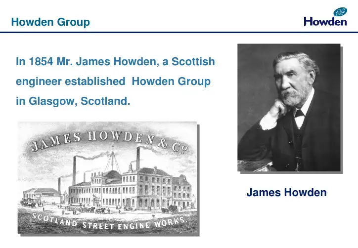
Howden GroupIn 1854 Mr. James Howden, a Scottishengineer established Howden Groupin Glasgow, Scotland.James HowdenHowden-Hua Engineering Co., Ltd.-Howden in ChinaIn 1994 Howden-Hua Engineering Co., Ltd.-a Joint Venture was established in Weihai City, Shandong Province P.R. China.Axial Flow FanJet Fan Howden-Hua ProductionsMixed Fan Cooling Fan Air Preheater Gas ReheaterCentrifugal FanTypical Arrangement of Duct System including APHAPH StructureTop Structure Gas DuctDrive UnitRotorSA DuctEnd PillarPA DuctHinged Side PillarBottom GirderAPH ConstructionThe Howden rotary regenerative air heater consists basically of the following parts:•Heating Surface Elements and Containers•Rotor in which the elements are packed•Rotor Housing in which the rotor rotates•End Pillars•Top Structure•Bottom Structure•Sealing Arrangements•Drive Unit•Rotor BearingsHeat Transfer Elements and Containers HS20HS 8 HS9(Corrugated Undulated )(Flat Notched Crossed Profile )(Double Undulated )Support barsDouble-Undulated profile optimised forenamelling and minimum pressure drop.Air Preheater leakageRotor Distortion and Leakage of Fixed Seal DesignVNFixed Seal DesignSite Erection sPreparation of the Client’s Support Steel Structure1.Check that the level and drilling ofthe supporting steelwork at the loadpoints are correct.ing the packers and shim materialprovided, level out the landingpoints on the supporting steelworkand tack weld the packing / levellingmaterial in position.3.The permissible differentialdeflection between any of thereheater support points ‘H’and ‘K’on the support steelwork should belimited to 10 mm. Measure andrecord the levelness of the ‘H’and ‘K’load points on the client’ssupporting steelwork.4.Tolerance = ±2 mm.Erections of Bottom girder and Bottom bearing2.Clean the bearing housing with wettish flour. Neverforget to pour lubricating oil on the surface of all the rollers and the bearing race immediately for antirust after assembling the bearing into the bottom bearing housing.3.The bottom bearing and housing should be centralisedwith respect to the girder ends (end pillar hingesmounting holes) . Shim to achieve the height as shownon the drawing.4.Assemble bottom bearing access platform to the bottomgirder as shown on the drawing. 1.Check orientation of gas reheater with supportingsteelwork in accordance with the generalarrangement drawing. Preassemble the bearing coverwith the bearing. Ensure that the spigot on thebottom face of the bearing cover correctly locateswith the inner ring of the bottom thrust bearing.1. Assemble the four end pillar hinges to thebottom girder. Shim to achieve height asshown in the drawing and secure with thebolts provided.2.Measure and record the levelness of theend pillar hinges.Tolerance = ±2 mm.End Pillar Hinges ErectionsMount the Bottom Structure1.Position the bottom structure ensuring thecorrect direction of tri-sector plate2.Position the bottom sector plates byensuring that the bottom bearing is in acentral location with respect to the bottom sector plate outside radius.Tolerance = ±2 mm.1.Ensure the correct orientation of end pillars.Check that both end pillars are vertical in bothdirections and that dimension between them iscorrect in accordance with the drawing.2.Measure and record the plumbness of the endpillars. Tolerance = 3 mm.3.Fit temporary stays to secure the verticallocations of the end pillars.Mount the end pillarsMount the Hub SpiderCare must be taken when lowering therotor spider to ensure that the recessin the bottom face of the rotor hubcorrectly locates with the spigot onthe jacking plate.Lift the spider and clean the bottom flangesurface of the spider. Remove burrs andrepair knocked marks if necessary.Install temporary props to hold the rotor spider level approx.Install the top structure1.Position the top structure onto the end pillarsand align according to the centrelines,ensuring that the hole on the top structure centralise the hub.2.Bolt together with end pillars by angles.Top structure Bop structureMount the Top Bearing Assembly.M36Eye BoltTo 2000Nm1.Carefully install the top bearing ass. snugly into spigot ofhub spider with the eye bolt after position the top glandseal2.Tighten the special bolts with required torque, while the thehead of bolts snugly contact the face of shaft.3.Adjust the relative elevation with the shims under thesupport channel4.Level the shaft end with theodolite by adjusting bolts tooland fit with screws.Mount the drive unit1.Measure and check the diameters ofbore for drive unit and shaftrespectively2.Carefully lift the drive unit through theshaft until locating on the shoulder ofshaft with special tools3.Install shrink disc as per requirementson the drawingMount the rotor housing on air side and tri-sector plates1.To enforce the stability of center section,assembly the air side housing and tri-sectorplate & axial plate2.Great attention must be taken to weld thejunction between tri-sectors.Mount the ducts on the air sideEnsure the ducts flange to take up the correct position as required, i.e. overlapping the inside edge of the housing landing plate by a nominal 20mmAssemble the Rotor Outer Sections1.Site assembly the rotorsections symmetricallydue to the ID platesstamped on the spiderand rotor sectionsrespectively2.Adjust the sections toensure that axial andradial swash between all24 radial plates must notbe exceeded ±3mm3.Adjust and average thepitches between outerrotor sections withspecial tools.Assemble the rotor-site welded sectors1.Assemble the site welded sectors/loose sector platesymmetrically due to ID plates between them andspider respectively, positioning hard against thelocating stops on the radial plates.2.Assemble the expansion joint to form connectionbetween one edge of portable out sector plate andradial plate.3.Measure the whole rotor assembly and tack weld iftolerance within required values.4.New designed rotor sections consist of 8 off37.5°outer sections and 7.5 loose sector divisionplates.Housing and Ducts on Gas Side Erection1. Mount the housing and ducts on gas side during rotor welding2. Weld the rotor according to thesequence shown on the drawing.3. Mount the partition plates afterfinishing the butt weld betweenradial division plates.4. Mount and weld the top and bottom tubular stiffeners, stiffeners platesand supporters plates as indicated on the drawings, except the bottom tubular stiffeners connecting to the bottom girder which should bewelded after loading heating elements.Load the element containers into rotor1.Load the element containers into the rotor compartments symmetricallyfrom inner ring2.Care must be taken to avoid damage of elements3.Apply with the special tool when loading cold element containers ifrequiredPreparation before Seal Setting1.Level the rotor within tolerance 3mm2.Adjust the elevation of rotor with hydraulic jacking by shims under bottombearing housing, ensuring that 120mm, dimension between edge of radial division plate and top flange of housing, is available3.Finish and check all necessary the welds, such as welds connecting bottomstructure and bottom girder and end pillar, welds connecting tubularstiffeners and bottom girder, etc.4.Check the supporter and lifting rod of connecting duct5.Remove any temporary supporter between non-metal expansion joint ,avoiding that external load transfer to static parts of APH6.Remove the temporary supporter of end pillar hinges and side pillarspletion of Client’s gas and air ducts and their hangers and supportserections, flexible expansion joints connections, and to ensure gas and air ducts are independently supported and are not transferring loads to APHs through the expansion joints,Seal setting-Top Radial Seal1.Select one radial division plate of mean size of swash and attachradial seal on it as a datum seal, protruding 40mm nominal size from top of radial division plate2.Withdraw some element containers on outer rings to take therecess to measure the clearance under the sector plates3.Adjust the top sector plate to clearances shown on the cold sealsetting chart, ensuring the tolerance as accurate as possible4.Apply 1~2mm bigger clearance to top tri-sector plate due to theoperation situation5.Tack weld and weld staggeringly and symmetrically by twowelders at least to minimize the deformation6.Measure the tolerance within 1.5mm max. after welding andadjust again if requiredSeal Setting-Bottom Radial Seal1.Select the same radial division plate as datum plate and attach bottom sealon it2.Withdraw some element containers on outer rings to take the recess tomeasure the clearance over the sector plates3.Adjust the bottom sector plate to required setting clearance at cappingpoints, ensuring the clearance as accurate as possible4.Apply same clearance to the three sector-plates5.Tack weld and weld staggeringly and symmetrically by two welders at leastto minimize the deformation6.Measure the tolerance within 1.5mm max. after welding and adjust again ifrequiredNote: the top sector plates must be readjusted if extreme bulge points over1.5mm on some area existSeal Setting-Axial Seal1.Select the same radial division plate as datum plate and attach axialseal on it2.Withdraw some element containers on outer rings to take the recess tomeasure the clearance over the axial plates3.Adjust the bottom axial plate to required setting clearance at cappingpoints, ensuring the clearance as accurate as possible4.Apply same clearance to the three axial plates5.Tack weld and weld staggeringly and symmetrically by two welders atleast to minimize the deformation6.Measure the tolerance within 3mm max. after welding and adjustagain if requiredWeld Joint between Axial and Sector Plates1.Measure the outer radial clearances and ensure clearanceswithin the required tolerance2.Weld staggeringly to minimize the welding deformation3.Measure all of the radial and axial setting clearances andensure them within required tolerance after welding while rotate the rotor whole one revolution, readjust if necessary 4.Grind flush after weldingRotor Tyres Setting1.Mount the top and bottom tyres and set the clearances between tyresand sector plates2.Set the one tyre as datum due to the cold seal setting chart , withreference to the extreme points on the outer sector plates3.Rotate the datum tyre one revolution and check the clearances, whichensure that minimal clearance between the tyre and sector plate equal to the setting clearance4.Assemble tyre setting bar according to the datum tyre5.Set the tyres with reference to the datum tyres6.Setting clearance of tyre must be kept enough margin to ensure safeoperation of APHFiller plate of Axial seal carrier bar1.Weld the filler plates between axial seal carrierbars and top/bottom tyres to fill the gap.2. The filler plates should be trimmed at site toaccommodate the gap.Top Radial Seals Erections1.Top radial setting barRotate the datum radial seal under one of edge of top sector plateReadjust the seal as datum seal to ensure that minimal clearance between datum seal and sector plates equal to setting clearance with reference to the extreme pointsRotate the seal one revolution and measure the clearances under top sector PlatesAssemble the top radial setting bar according to datum seal2.Install the top seals as per the seal setting bar3.Great care must be taken to ensure the installation of seals as accurate aspossible, which mainly influence the leakage and safety operation of APH.Bottom radial Seals and Axial SealsInstall the bottom radial and axial seals respectively same as the above procedureInner circumferential seals1.Mount the inner circumferential sealbefore installation of radial seal2.Set the clearance with reference tocold seal setting chart.Outer circumferential sealsTop Circumferential Seal1. Trim the tyres as roundness within 3mm byflame cutting, which set up the clearance toaxial seal plates as per cold seal setting chart.Rotate the rotor tyres 360°and measure from afixed point and record the minimum clearance.Mark the extreme point on the tyre.2. Mount the top outer circumferential seals as percold seal setting chart, with reference to themarked extreme point. Rotate the rotor tyresand check the clearance after welding.Bottom Circumferential Seal1. Treat the bottom tyres as above.2. Mount the bottom circumferential seal according to the cold seal settingchart. Rotate the rotor tyres and check the clearance.Hub Seal and Gland SealTop StructureAuxiliary Equipment Erections and Commissioning1.Mount the soot blowers as per drawing2.Mount the fire detection probes and connect the cables tothe control panel3.Mount the rotor stop alarm and connect the cables to thecontrol panel4.Mount the fire fighting devices as per drawing and connectthe pipelines5.Mount the inspection window as per drawingSteam SootblowingParameters for Steam cleaning:•Inlet Pressure:1.5 M Pa;•Pressure at Nozzle Outlet:0.93 M Pa ∼1.07 M Pa;•Degree of Superheat:110 ℃。