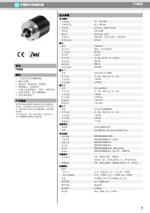
P+F_多圈绝对值编码器FVM58
- 格式:pdf
- 大小:1.03 MB
- 文档页数:6
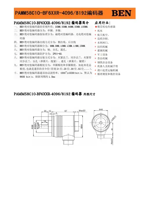
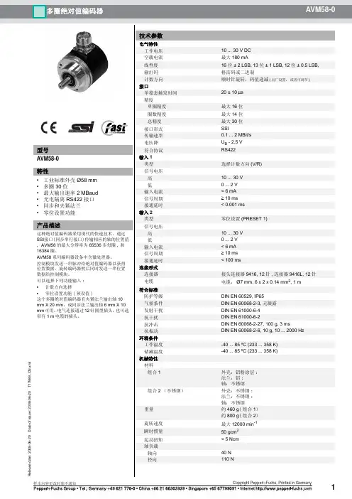
PAMM58C10-BF6XXR-4096/8192编码器简介 应用行业:一. BEN 绝对值编码器的常规外形:38MM,58MM,66MM,80MM.100MM.二. BEN 绝对值编码器分为:单圈,多圈。
三. BEN 绝对值编码器按原理分为:磁绝对值编码器,光电绝对值编码器四. BEN 绝对值编码器出线方式分为:侧出线,后出线五. BEN 绝对值编码器轴分为:6MM,8MM,10MM,12MM,14MM,25MM.六. BEN 绝对值编码器分为:轴,盲孔,通孔。
七.BEN 绝对值编码器防护分为:IP54-68.八. BEN 绝对值编码器安装方式分为:夹紧法兰、同步法兰、夹紧带同步法兰、盲孔(弹簧片,抱紧)、通孔(弹簧片,键销)九. BEN 绝对值编码器精度分为:单圈精度和多圈精度,加起来是总精度,也就是通常的多少位(常规24位,25位,30位,32位。
)。
十. BEN 绝对值编码器通讯协议波特率:4800~115200 bit/s,默认为9600 bit/s。
刷新周期约1.5ms ★精芬机电传感器 * 机床 * 航天航空、 * 造纸印刷、 * 水利闸门、 * 纺织机械 * 灌溉机械 * 军工设备 * 食品机械 * 钢铁冶金设备 * 机器人及机械手臂 * 港口起重运输机械 * 精密测量和数控设备PAMM58C10-BF6XXR-4096/8192编码器 外形尺寸PAMM58C10-BF6XXR-4096/8192编码器技术参数BEN编码器的发展,从增量值编码器以转动时输出脉冲,通过计数设备来计算其位置,当编码器不动或停电时,依靠计数设备的内部记忆来记住位置。
这样,当停电后,编码器不能有任何的移动,当来电工作时,编码器输出脉冲过程中,也不能有干扰而丢失脉冲,不然,计数设备计算并记忆的零点就会偏移,而且这种偏移的量是无从知道的,只有错误的生产结果出现后才能知道。
解决的方法是增加参考点,编码器每经过参考点,将参考位置修正进计数设备的记忆位置。
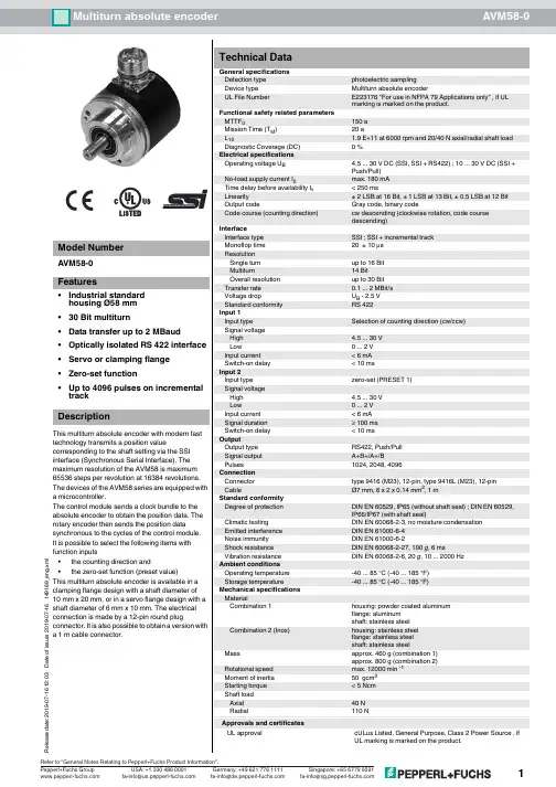
19-07-16 12:03D a t e o f i s s u e : 2019-07-16t 49169_e n g .x m l** Aluminium: d = 59, stainless steel: d = 61** Aluminium: d = 59, stainless steel: d = 6119-07-16 12:03D a t e o f i s s u e : 2019-07-16t 49169_e n g .x m l19-07-16 12:03D a t e o f i s s u e : 2019-07-16t 49169_e n g .x m l19-07-16 12:03D a t e o f i s s u e : 2019-07-16t 49169_e n g .x m lThe Synchronous Serial Interface was specially developed for transferring the output data of an absolute encoder to a control device. The control module sends a clock bundle and the absolute encoder responds with the position value.Thus only 4 lines are required for the clock and data, no matter what the resolution of the rotary encoder is. The RS 422 interface is optically isolated from the power supply.SSI signal course Standard•At idle status signal lines "Data +" and "Clock +" are at high level (5V).•The first time the clock signal switches from high to low, the data transfer in which the current information (position data (D n ) and special bit (S)) is stored in the encoder is introduced.•The highest order bit (MSB) is applied to the serial data output of the encoder with the first rising pulse edge.•The next successive lower order bit is transferred with each following rising pulse edge.•After the lowest order bit (LSB) has been transferred the data line switches to low until the monoflop time T m has expired.•No subsequent data transfer can be started until the data line switches to high again or the time for the clock pause T p has expired.•After the clock sequence is complete, the monoflop time T m is triggered with the last falling pulse edge.•The monoflop time T m determines the lowest transmission frequency.SSI output format ring slide operation (multiple transmission)•In ring slide operation, multiple transmission of the same data word over the SSI interface makes it possible to offer the possibility of detecting transmission errors.•In multiple transmission, 25 bits are transferred per data word in standard format.•If the clock change is not interrupted after the last falling pulse edge, ring slide operation automatically becomes active. This means that the information that was stored at the time of the first clock change is generated again.•After the first transmission, the 26th pulse controls data repetition. If the 26th pulse follows after an amount of time greater than the monoflop time T m , a new current data word will be transmitted with the following pulses.If the pulse line is exchanged, the data word is generated offset.Ring slide operation is possible up to max. 13 bits.Block diagram Line lengthDescriptionLine length in mBaudrate in kHz< 50< 400< 100< 300< 200< 200< 400< 10019-07-16 12:03D a t e o f i s s u e : 2019-07-16t 49169_e n g .x m lThe selection of the counting direction input (V/R) is activated with 0-level. The zero-set input (PRESET 1) is activated with 1-level.Signal outputsInputs! cw - with view onto the shaft19-07-16 12:03D a t e o f i s s u e : 2019-07-16t 49169_e n g .x m lFor additional information on the accessories, please see the "Accessories" section.For typeAccessoriesName/defining feature Order codeAVM58*-011CouplingsD1: Ø10 mm, D2: Ø10 mm9401D1: Ø10 mm, D2: Ø10 mm 9404D1: Ø10 mm, D2: Ø10 mm 9409D1: Ø10 mm, D2: Ø10 mm KW Measurement wheels with circumference of 500 mmPlastic9101, 10Pimpled rubber 9102, 10Knurled aluminium 9103, 10Knurled plastic 9112, 10Measurement wheels with circumference of 200 mmPlastic9108, 10Pimpled rubber 9109, 10Knurled aluminium 9110, 10Knurled plastic9113, 10Mounting aidsMounting bracket 9203Mounting bracket 9213AVM58*-032CouplingsD1: Ø6 mm, D2: Ø6 mm 9401D1: Ø6 mm, D2: Ø6 mm9402D1: Ø6 mm, D2: Ø6 mm 9404D1: Ø6 mm, D2: Ø6 mm 9409D1: Ø6 mm, D2: Ø6 mmKWMounting aidsMounting bracket and set 9300 and 9311-3Eccentric clamping elements 9310-3AllConnectorsCable socket 9416Cable socket9416L19-07-16 12:03D a t e o f i s s u e : 2019-07-16t 49169_e n g .x m lA V M 58–0–Number of bits singleturn 124096 (standard)1381921665536Number of bits multiturn124096 (standard)1416384Options N Standard1Incremental track 1024 pulses, Push/Pull 2Incremental track 2048 pulses, Push/Pull 3Incremental track 4096 pulses, Push/Pull 4Incremental track 1024 pulses, RS4225Incremental track 2048 pulses, RS4226Incremental track 4096 pulses, RS422Output codeB Binary GGrayExit position A Axial RRadialConnection typeK1Cable Ø7 mm, 6 x 2 x 0.14 mm², 1 m AA Plug connector type 9416, 12-pin ABPlug connector type 9416L, 12-pinShaft dimension/flange version011Shaft Ø10 mm x 20 mm with clamping flange 032Shaft Ø6 mm x 10 mm with servo flangeHousing material N Aluminium, powder coated IInox*Principle of operation M MultiturnShaft versionV Solid shaftData formatASSI (Synchronous Serial Interface)*Housing material I only available with axial exit position.。

北京多圈齿轮组光电绝对值编码器原理1.多圈齿轮组多圈齿轮组是编码器的核心部分,它由多个齿轮组成,每个齿轮上都有一定数量的刻线。
这些刻线根据二进制编码原理,可以表示不同的位置。
齿轮之间通过传动链条、带轮或直接啮合的方式连接。
2.光电传感器编码器中的光电传感器用于读取多圈齿轮组上的刻线信息。
光电传感器通常由光发射器和光接收器组成。
光发射器发射一束光束,光接收器检测到光束的反射或透过。
当光束照射到刻线上时,光接收器将检测到光的变化,产生相应的电信号。
3.二进制编码原理多圈齿轮组上的刻线可以表示二进制编码,由此实现对位置信息的测量。
这里以2圈齿轮组为例,每个齿轮上有4个刻线,可以表示4个位置。
其中,第一圈齿轮上的刻线按顺时针方向编码为00、01、10、11,第二圈齿轮上的刻线也按顺时针方向编码为00、01、10、11、通过识别两个齿轮上的刻线组合,可以准确测量到物体的位置。
4.工作原理在编码器工作时,物体的位置信息通过多圈齿轮组的转动传递给光电传感器,光电传感器识别到刻线并输出对应的电信号。
根据接收到的电信号,可以精确计算出物体的角度、距离或速度等位置信息。
5.应用领域北京多圈齿轮组光电绝对值编码器广泛应用于机械工程、自动化控制、航天航空等领域。
它可以实现对工业机械设备的精确定位和测量,提高生产效率和质量。
同时,由于其精确性和可靠性,也被用于科学研究、医疗设备等领域。
总结:北京多圈齿轮组光电绝对值编码器通过多圈齿轮组和光电传感器的结合,实现对物体位置的测量。
它利用多圈齿轮组上的刻线和光电传感器的工作原理,识别刻线并输出相应的电信号。
该编码器具有精度高、测量范围广、响应速度快的特点,在工业和科研领域有广泛的应用。

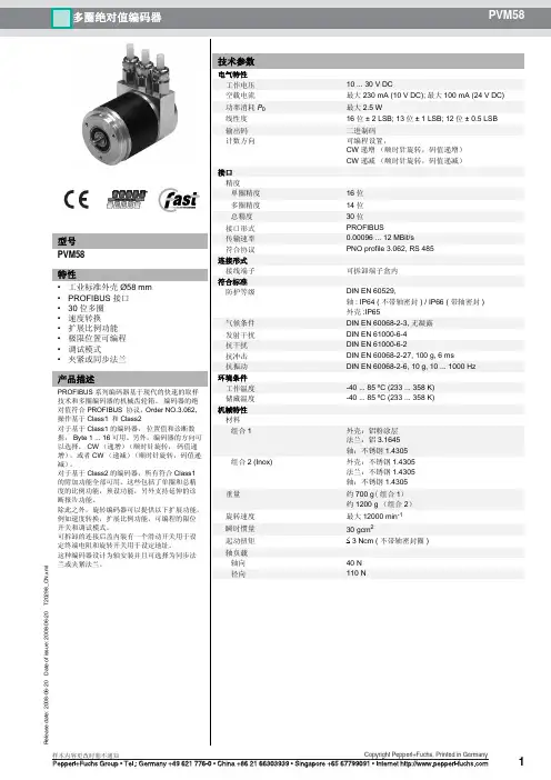
倍加福P+F多圈绝对值编码器PVM58系列技术说明
倍加福P+F多圈绝对值编码器PVM58系列特点:工业标准外壳∅58 mm PROFIBUS 接口
30 位,多匝
速度传输
更广泛的扩展功能
可编程的限位开关
调试模式
伺服或夹紧法兰
倍加福P+F多圈绝对值编码器PVM58系列技术参数:
检测类型光电采样
设备类型多圈绝对值编码器工作电压10 ... 30 V DC
空载电流最大 230 mA 在 10 V DC 时最大 100 mA 在 24 V DC 时
功耗最大 2,5 W
可用前的时间延迟< 1000 ms
线性度±在 16 位时为 2 LSB,在 13 位时± 1 LSB,在 12 位时输出码二进制码
Code course(计数方向)可编程,
顺时针递增(顺时针旋转,code course 递增)顺时针递减(顺时针旋转,code course 递减)
接口类型PROFIBUS
分辨率
单圈可达 16 Bit
多匝14 Bit。

AVM58N-011K1R0GN-1213编码器简介应用行业: 一. BEN 绝对值编码器的常规外形:38MM,58MM,66MM,80MM.100MM.二. BEN 绝对值编码器分为:单圈,多圈。
三. BEN 绝对值编码器按原理分为:磁绝对值编码器,光电绝对值编码器四. BEN 绝对值编码器出线方式分为:侧出线,后出线五. BEN 绝对值编码器轴分为:6MM,8MM,10MM,12MM,14MM,25MM.六. BEN绝对值编码器分为:轴,盲孔,通孔。
七. BEN 绝对值编码器防护分为:IP54-68.八. BEN 绝对值编码器安装方式分为:夹紧法兰、同步法兰、夹紧带同步法兰、盲孔(弹簧片,抱紧)、通孔(弹簧片,键销)九. BEN 绝对值编码器精度分为:单圈精度和多圈精度,加起来是总精度,也就是通常的多少位(常规24位,25位,30位,32位。
)。
十. BEN 绝对值编码器通讯协议波特率:4800~115200 bit/s,默认为9600 bit/s。
刷新周期约1.5ms ★精芬机电传感器 * 机床 * 航天航空、 * 造纸印刷、 * 水利闸门、 * 纺织机械 * 灌溉机械 * 军工设备 * 食品机械 * 钢铁冶金设备 * 机器人及机械手臂 * 港口起重运输机械 * 精密测量和数控设备AVM58N-011K1R0GN-1213编码器 外形尺寸AVM58N-011K1R0GN-1213编码器技术参数BEN编码器的发展,从增量值编码器以转动时输出脉冲,通过计数设备来计算其位置,当编码器不动或停电时,依靠计数设备的内部记忆来记住位置。
这样,当停电后,编码器不能有任何的移动,当来电工作时,编码器输出脉冲过程中,也不能有干扰而丢失脉冲,不然,计数设备计算并记忆的零点就会偏移,而且这种偏移的量是无从知道的,只有错误的生产结果出现后才能知道。
解决的方法是增加参考点,编码器每经过参考点,将参考位置修正进计数设备的记忆位置。
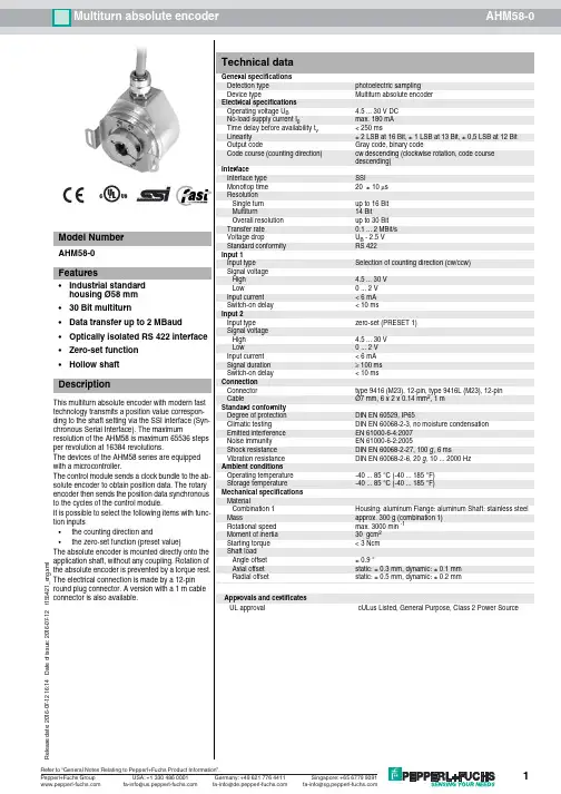
12R e l e a s e d a t e : 2 0 1 6 -0 7 -1 2 1 6 : 1 4 D a t e o f i s s u e : 2 0 1 6 -0 7 -1 2 t 1 5 5 4 2 1 _ e n g . x m lDimensions3R e l e a s e d a t e : 2016-07-12 16:14D a t e o f i s s u e : 2016-07-12t 155421_e n g .x m l4R e l e a s e d a t e : 2016-07-12 16:14D a t e o f i s s u e : 2016-07-12t 155421_e n g .x m lThe Synchronous Serial Interface was specially developed for transferring the output data of an absolute encoder to a control device. The control module sends a clock bundle and the absolute encoder responds with the position value.Thus only 4 lines are required for the clock and data, no matter what the resolution of the rotary encoder is. The RS 422 interface is optically isolated from the power supply.SSI signal course Standard•At idle status signal lines "Data +" and "Clock +" are at high level (5V).•The first time the clock signal switches from high to low, the data transfer in which the current information (position data (D n ) and special bit (S)) is stored in the encoder is introduced.•The highest order bit (MSB) is applied to the serial data output of the encoder with the first rising pulse edge.•The next successive lower order bit is transferred with each following rising pulse edge.•After the lowest order bit (LSB) has been transferred the data line switches to low until the monoflop time T m has expired.•No subsequent data transfer can be started until the data line switches to high again or the time for the clock pause T p has expired.•After the clock sequence is complete, the monoflop time T m is triggered with the last falling pulse edge.•The monoflop time T m determines the lowest transmission frequency.SSI output format ring slide operation (multiple transmission)•In ring slide operation, multiple transmission of the same data word over the SSI interface makes it possible to offer the possibility of detecting trans-mission errors.•In multiple transmission, 25 bits are transferred per data word in standard format.•If the clock change is not interrupted after the last falling pulse edge, ring slide operation automatically becomes active. This means that the infor-mation that was stored at the time of the first clock change is generated again.•After the first transmission, the 26th pulse controls data repetition. If the 26th pulse follows after an amount of time greater than the monoflop time T m , a new current data word will be transmitted with the following pulses.If the pulse line is exchanged, the data word is generated offset.Ring slide operation is possible up to max. 13 bits.Block diagram Line lengthThe selection of the counting direction input (V/R) is activated with 0-level. The zero-set input (PRESET 1) is activated with 1-level.DescriptionInputsLine length in mBaudrate in kHz< 50< 400< 100< 300< 200< 200< 400< 1005R e l e a s e d a t e : 2016-07-12 16:14D a te of i s s u e : 2016-07-12t 155421_e ng .x m l6R e l e a s e d a t e : 2016-07-12 16:14D a t e o f i s s u e : 2016-07-12t 155421_e n g .x m lFor additional information on the accessories, please see the "Accessories" section.AccessoriesAccessories Name/defining feature Order codeConnectorsCable socket 9416Cable socket9416LOrder codeA H 58–O A R N –Number of bits singleturn 124096 (standard)1381921665536Number of bits multiturn00for singleturn-encoders 124096 (standard)1416384Output code B Binary G GrayOption H Hardware encoder 0Zero set functionExit positionRRadialConnection typeK1Cable Ø7 mm, 6 x 2 x 0.14 mm2, 1 m AA Plug connector type 9416, 12-pin ABPlug connector type 9416L, 12-pinShaft dimension/flange versionOAA Hollow shaft with Ø10 mm OBAHollow shaft with Ø12 mmHousing material NAluminiumPrinciple of operationS Singleturn M MultiturnWellenausführungH Hollow shaftData formatASSI (Synchronous Serial Interface)。
绝对值编码器的工作原理绝对值编码器是一种用于测量旋转位置的装置,它能够提供与旋转角度相关的绝对位置信息。
在工业自动化、机器人控制、数控机床等领域中广泛应用。
本文将详细介绍绝对值编码器的工作原理。
一、绝对值编码器的基本结构绝对值编码器由光栅盘、读取头和信号处理电路组成。
光栅盘是一个圆盘形状的光透过的编码器,上面有许多等距的光栅线。
读取头是由发光二极管和光敏二极管组成的光电传感器,用于读取光栅盘上的光栅线。
信号处理电路负责将光电传感器读取到的光栅信号转化为可用的绝对位置信息。
二、绝对值编码器的工作原理绝对值编码器的工作原理可以分为两个步骤:光栅盘的读取和信号处理。
1. 光栅盘的读取当绝对值编码器旋转时,光栅盘上的光栅线会经过读取头。
读取头中的发光二极管会发出光线,光线经过光栅盘上的光栅线后被光敏二极管接收。
光敏二极管会将接收到的光信号转化为电信号,并传送到信号处理电路中。
2. 信号处理信号处理电路接收到光敏二极管传来的电信号后,会对信号进行处理,以获取绝对位置信息。
信号处理电路会根据光栅盘上的光栅线数量和罗列方式,将接收到的信号转化为二进制码。
每一个光栅线对应一个二进制位,通过读取头读取到的信号可以确定每一个二进制位的值。
将这些二进制位组合起来,就可以得到绝对位置的编码。
三、绝对值编码器的优势相比于增量式编码器,绝对值编码器具有以下优势:1. 不需要参考点:绝对值编码器可以在任意位置上电后即将提供准确的绝对位置信息,不需要进行复位操作。
2. 高精度:由于绝对值编码器可以提供每一个位置的具体编码,因此具有更高的精度。
通常,绝对值编码器的分辨率可以达到几个微米。
3. 可靠性高:绝对值编码器的工作不受外部干扰的影响,具有较高的抗干扰能力。
4. 快速响应:绝对值编码器的读取和信号处理速度较快,能够实时提供旋转位置信息。
四、应用领域绝对值编码器广泛应用于工业自动化、机器人控制、数控机床等领域。
在机器人控制中,绝对值编码器可以用于测量机器人关节的旋转角度,从而实现精确的位置控制。
P+F倍加福编码器说明书旋转编码器可以用来测量旋转速度,加速度,位置和方向。
BEN编码器可以应用在大量的机械工程行业,例如物料输送、物流和包装行业。
在工业自动化领域中,旋转编码器可以被用作测量角度、位置、速度和角速度,通过使用齿条、测量轮以及恒力开度仪我们可以测量直线的运动位置。
旋转编码器可以将机械的输入转换为电气信号,这个电气信号可以通过计数器、转速表、可编程逻辑控制器(例如PLC)和工业计算机进行处理。
随着高性能高速运转机器的不断制造,工业电机、设备、厂房系统的制造商们将注意力都集中在了机器安全的问题上。
工业机器人和自动送料系统的使用会对操作人员产生潜在的危险和风险。
为响应这一危险局势,倍加福制定了一系列认证的旋转编码器,利用创新的理念使系统集成更为经济。
新的思想利用传感器组件和工厂控制系统之间现有的通信路径简化了他们的应用,从而使BEN编码器可以应用在安全等级高达SIL3 的工厂中(符合IEC 61508)主要系列有RVI58N-011K1R61N-01024RVI78N-10CK2A31N-01000RVI50N-09BK0A3TN-01024RVI58N-011K1R61N-01000RVI50N-09BK0A3TN-01000PVM58N-011AGR0BN-1213编码器P+F编码器 PEPPERL+FUCHS P+F AVM58N-011AAROBN-1212PEPPERL+FUCHS P+F RVI50N-09BK0A3TN-01000PEPPERL+FUCHS P+F AVS58N-011AAROGN-0012RVI50系列我上海精芬销售倍加福全系列产品,价格最优。
产品介绍:RVI50系列编码器展示图片:详细说明:RVI58系列产品介绍:展示图片:详细说明:WCS3B-LS246位置编码器/工控系统展示图片:详细说明:DVM58系列产品介绍:倍加福编器DVM58系列现货特价展示图片:详细说明:RHI58系列产品介绍:倍加福编码器RHI58系列大量现货特价展示图片:详细说明:倍加福编码器RHI58系列大量现货特价RHI58N-**AK1R**N-******轴尺寸:0A 轴套直径10mm0B轴套直径12mm*信号输出:6 A+B+Z*输出电路:1:10-30V6:5V RS-422X: 10-30V RS-422****脉冲数:100、360、500、512、1000、1024、1250、2000、2048、2500、3600、4096、5000RHI90N系列产品介绍:展示图片:详细说明:倍加福系列编码器精芬机电大量库存现特价PVM58N-011AGR0BN-1213PVM58N-032AGR0BN-1213PVM58N-021AGR0BN-1213PVM58N-022AGR0BN-1213PVM58N-011AZR0BN-1213PSM58N-F3AAGR0BN-1213FVS58N-011K2R3GN-0013PVM58N-011AGR0BN-1213PVI58N-011AGR0BN-1213RVI50N-09BK0A3TN-01000RHI90N-0HAK1R61N-01024RHI90N-0HAK1R61N-01024RVI50N-09BK0A3TN-01000RVI58N-011K1R61N-01024参数表节选:的技术参数RHI90N-*******1PVM58系列产品介绍:PVM58N-011AGROBN-1213大量库存展示图片:详细说明:常用型号PVM58N-011AGROBN-1213 大量现货卷板机恒力开度仪SL3002-X1/GS80/K/01 links产品介绍:SL3002-X1/GS80/K/01 links展示图片:详细021介绍39536219SL3002-X1/GS80/K/01 rechts SL3002-X1/GS80/K/01 links SL3002-X1/GS80-200。
小型绝对单圈编码器EAB50小型绝对值单圈编码器EAB50系列,结构合理紧凑,能承受较高的轴向和径向负载。
标准法兰,集夹紧法兰和同步法兰为一体,多种预留螺孔方便客户安装,多应用于角度测量和定位应用,在纺织行业表现尤为突出。
标准轴型绝对单圈编码器EAC58标准绝对值单圈编码器EAC58系列,用于工业环境,具有良好的抗机械损伤性能,能够承受较高的轴向和径向负载。
机械上多种法兰和电气上多种输出形式可供客户选择,分辨率最大可达8192分辨率,有预设复位功能可为用户提供更方便的校正操作。
标准轴套型绝对单圈编码器EAC58P标准绝对值单圈编码器EAC58P系列,用于工业环境,具有良好的抗机械损伤性能,能够承受较高的轴向和径向负载。
机械上多种法兰和电气上多种输出形式可供客户选择,分辨率最大可达8192分辨率,有预设复位功能可以及时进行校正操作。
增量绝对双输出编码器EAD58增量绝对双输出编码器EAD58系列,用于有特殊需求的工业环境,具有良好的抗机械损伤性能,在轴上能承受较高的轴向和径向负载。
其电气结构既满足了绝对值测量功能,又满足了增量型测速的需要,与所有知名上位机均可配合使用,满足了特殊环境的特殊需求。
大型绝对单圈编码器EAC90/115大型绝对值单圈编码器EAC90系列,用于工业环境,具有良好的抗机械损伤性能,能够承受较高的轴向和径向负载。
机械上标准法兰和电气上多种输出形式可供客户选择,分辨率最大可达8192分辨率,有预设复位功能按键。
Profibus绝对多圈编码器PAM58/90/115Profibus绝对值多圈编码器PAM58系列,用于工业环境,具有良好的抗机械损伤性能,能够承受较高的轴向和径向负载。
机械上各种法兰可以满足用户不同的需求,电气上符合Profibus协议,最大分辨率8192最大圈数4096圈,分辨率和圈数可根据客户现场需要而调节。
其高速通讯和良好的抗干扰...标准绝对多圈编码器EAMM58标准绝对值多圈编码器EAMM58系列,用于工业环境,具有良好的抗机械损伤性能,能够承受较高的轴向和径向负载。