SIMATIC Sensors - Safety 产品概述
- 格式:pdf
- 大小:717.15 KB
- 文档页数:22

Which sensors can be connected?SIRIUS ACT EMERGENCY STOP 3SU18command devicesSIRIUS 3SE29/39 foot switchesSIRIUS ACT 3SU1 two-hand operation consolesSIRIUS 3SE7cable-operated switchesSIRIUS 3SE5 position and safety switchesSIRIUS 3SE6 non-contact safety switchesIntegrated and efficientsafety chain2SIRIUS 3RT contactorsSIRIUS 3RA6 compact startersSIRIUS 3RM1 motor startersFrom detecting to evaluating and reacting.Sensors and actuators work together perfectly to create the ideal conditions for complete safety chains with SIRIUS Safety. These chains are not only extremely reliable but are also much quicker and easier to set up.An important element are the position and safety switches.P r o t e c t iv ed o o rE m e r g e n c ys t o pL i g h t a r r a yL a s e r s c a n n e rM a tT w o -h a n dc o n t r o lpa n e lT i m e -d e l a y e ds h u t d o wn P r o t e c t i v e d o o rw i t hl o c k i n gd e v i c eI n d e p e n d e n to u t p u tf u n c t i o nsM u t i n g1234EN 50 047Main advantages at a glance• Reduced variance and stock-keeping costs due to modular design• Plug-in design and a standardized interface simplify replacement and installation of the actuator heads • All actuator heads can be rotated in 22.5° increments • Quick-connect technology for plastic enclosures (31 mm) reduces mounting times by up to 25%• Choice of connectors and rollers• The entire ASIsafe electronics is integrated in a standard enclosure• LED displays optionally available for all enclosures • Higher degree of safety with redundant shutdown and additional signaling for versions with 3-pole contact blocks (enclosure dimensions as for 2-pole contact blocks)• Versions with increased corrosionprotection and for use down to –40°CSIRIUS position switches4Complete unitsPlastic or metal enclosure 31 mm wide, according to EN 50 047, with snap-action contacts 1 NO / 1NCRounded plunger, high-grade steel––Roller plunger X–Roller lever–X 3SE5122-0CH01Twist lever–X3SE5122-0CH50Twist lever, infinitely adjustable length–X= p ositive opening* – =withhigh-gradesteel roller** – =withplasticroller Our position switches can be ordered in a modular design or as complete units – already fitted with an actuator head. You will find further versions, such as compact switches, non-encapsulated designs or switches for ambient temperatures down to –40°C at: /sirius/configurators5Mechanical safety switcheswith separate actuatorsSafety switches with a separate actuator are used where the position of doors, covers or protective grilles must be monitored for safety reasons. 3SE5 safety switches with a separate actuator without a locking device have the same enclosures as the 3SE5 position switches (modular system). Safety switches with a locking device 3SE53 are special safety-related devices which prevent an unforeseen or intentional opening of protective doors, protective grilles or other covers for as long as a dangerous situation is present (i.e. follow-on motion of the switched-off machine).63SE5000-0AB01–––3SE5000-0AD053SE5000-0AC03–––3SE5000-0AE05––3SE5000-0AF05–3SE5000-0AR01––+3SE5000-0AH00++–3SE5000-0AA013SE5000-0AA02–3SE5000-0AA113SE5000-0AA12–3SE5000-0AA503SE5000-0AA51–3SE5000-0AA603SE5000-0AA613SE5000-0AA80––3SE5000-0AA82––= p ositive openingPlain plunger Rounded plunger Roller plunger Roller lever Angular roller lever Spring rod Twist actuatorAdjustable-lengthtwist lever7Plain plungerRounded plunger (with overtravel)Roller plunger (with overtravel)Roller leverAngular roller leverSpring rod Twist actuatorAdjustable-lengthtwist lever3SE5000-0AB01––3SE5000-0AC02––––3SE5000-0AD02–3SE5000-0AE013SE5000-0AE02–3SE5000-0AE033SE5000-0AE04–3SE5000-0AF013SE5000-0AF02–3SE5000-0AF033SE5000-0AF043SE5000-0AR01–– +3SE5000-0AH00++–3SE5000-0AA013SE5000-0AA02–3SE5000-0AA113SE5000-0AA12–3SE5000-0AA503SE5000-0AA51–3SE5000-0AA603SE5000-0AA613SE5000-0AA80––3SE5000-0AA82––= p ositive opening8Non-contact RFID safety switches: An RFID safety switch consists of a coded RFID switch with an 8-pole M12 3SE6315-0BB02-1AP0Individually coded, multiple teach-in capability3SE6315-0BB03-1AP0Individually coded, single teach-in3SE6310-0BC01StandardNon-contact RFID safety switches with tumbler, locking force 1150N: An RFID safety switch with tumbler 3SE6415-1BB02Closed-circuit principle, individually coded, multiple teach-in capability3SE6415-1AB01Open-circuit principle, family coded3SE6415-1AB02Open-circuit principle, individually coded, multiple teach-in capability3SE640-1AC01Standard*Connection cable for both types of safety switches available in 3, 5, 10 and 15 metersNon-contact safety switchesThe SIRIUS 3SE63 RFID safety switches without tumbler and magnetically-operated switches and the 3SE64 RFID safety switches with tumbler and magnetically-operated switches leave no room for tampering. They conform to market safety requirements with maximum tamper resistance according to ISO 14119 as well as safety requirements according to SIL 3 (IEC 62061/IEC 61508) or PL e (ISO 13849-1) for monitoring the positions of movable protective devices.In the case of protective door tumblers, 3SE64 RFID safety switches provide reliable protection against dangerous follow-on motion and are suitable for protecting both people and processes. The unique rotating shaft and hub operating principle makes it possible to pull the protective door shut (latch force can be set to 25 N or 50 N) to an almost backlash-free end posi-tion with a simultaneous tumbler that even serves as a door stop, eliminating the need for an additional door stop.Non-contact magnetically operated safety switch: A magnetically operated switch comprises a coded switching 3SE6604-2BA With cable 3 m, 2NC 3SE6604-2BA01With M8 plug, 4-pole, 2NC 3SE6604-2BA10With cable 10 m, 2NC 3SE6605-2BA With cable 3 m, 1NO +1NC 3SE6605-2BA01With M8 plug, 4-pole, 1NO +1NC 3SE6614-4CA01With M8 plug, 4-pole, 2NC, LED3SE6704-2BA For 3SE660* versions 3SE6714-2BA For 3SE661* versions 3SE6605-3BA With cable 3 m, 1NO +1NC 3SE6605-3BA05With cable 5 m, 1NO +1NC 3SE6605-3BA10With cable 10 m, 1NO +1NC3SE6616-3CA01With 8 mm latching connection, 6-pin connector, 1NO +1NC +1NC 1)3SE6617-3CA01With 8 mm latching connection, 6-pin connector,1NO +1NC +1NC 1)3SE6627-3CA04With cable 3 m, 2NC +1NC 1)3SE6704-3BA For 3SE660* versions 3SE6714-3CA For 3SE661*/3SE662* versions3SX5601-3GA05 5 m, M8 socket, 4-pole3SX5601-4GA055 m, socket 8 mm, latching connection 6-pole 1)Signaling contact9SIL 3/PL eSIL 3/PL eSIL 3/PL eSIL 3/PL eSIL 3/PL eSIL 3/PL eWith 2x switches(enabling individual switch combinations)Maximum safetySafety Integrity Level SIL (IEC 62061/ IEC 61508)/Performance-Level PL (ISO 13849-1)With 1x switchMonitoring of 1 NO contactMonitoring of 1 NO contactMonitoring of 1 NO contactMonitoring of 2 NO contacts or 1 NO and 1 NC contactMonitoring of 2 NO contacts or 1 NO and 1 NCcontact Monitoring of 2 NO contacts or 1 NO and 1 NC contact SIL 1/PL c SIL 1/PL c SIL 1/PL c SIL 1/PL c SIL 2/PL d SIL 2/PL d Design type112Mechanical position and safety switchesSIMATIC ET 200SPSIRIUS 3SK safety relaysSIMATIC controllerSafety switches with separateStandard/compact 3SE51/3SE52/3SE54 3SF1 AS-i variantTampering protection(Acc. to DIN EN ISO 14119, TÜV certificate)low,actuator head uncoded Positive opening operation as per IEC 60947-5-1, positive drive, necessary in safety applicationslow,shaft uncoded low,3D-coded actuator without tumbler 3SE51/3SE52 3SF1 AS-i variantSafety hinge 3SE51/3SE52 3SF1 AS-i variantDetectingEvaluatingApplication examplesWith the position and safety switches almost all requirements in the industry can be met.Various application examples e.g. forguard door monitoring can be found here:Position switch with twist lever:Detection of positions and end positions of moving machine and system parts, such as e.g. conveyor belts and assembly linesPivoting doors and flaps, with fixedpositive connection between switch and door hinge, switching angle 10°Roller door or position monitoring of grilles or doors/cs/ww/en/ps/16403/ae/et200sp/safety-relays /simatic-safety1.) Without tumbler2.) W ith lockingdeviceSIRIUS Position and Safety Switches10SIL 3/PL e SIL 3/PL e Monitoring of 1 NO contact Monitoring of 2 NO contacts or 1 NO and 1 NC contactMonitoring of 2 NO contacts or 1 NO and 1 NC contact Self-monitoring with 2 electronic 0SSD safety outputsSelf-monitoring with 2 electronic0SSD safety outputs SIL 1/PL c SIL 3/PL e SIL 3/PL eSIL 3/PL eSIL 2/PL d 2444 actuatorNon-contact safety switches low, 3D-coded actuatorlow, coded switching magnet low or high (to choose), coded RFID security switches low or high (to choose), coded RFID security switches Magnet safety switches 3SE66/3SE67with tumbler 3SE53 3SF1 AS-i variant RFID safety switches 3SE63RFID safety switches with tumbler 3SE64Additional interlocking requirement, e.g. in the working area of a robot system: Shutdown of machines requires closed safety doors with tumbler guarding Monitoring of maintenance flaps (hoods, doors, grilles), especially suitable for confined spaces Monitoring of swing doors, flaps, hoods, grilles, vibration-proof and robust IP69, large switching interval Interlocking requirement for rotating, laterally movable or removable safety guards IP69, with latching, optimized hygiene standard with simultaneous highest personnel and process protection Application manual SIRIUS Safety IntegratedDownload here11Technical information and support are available at/SIOSor in the Industry Online Support App.Available for Android and iOsr e l y generalf or m a nce which in case of ac t p ly ast her de v e lpmSecurity information/industrialsecurity.。
西门子操作面板产品介绍 11. 2011致力于满足您的各种需求满足您所有需要的操作员面板多年以来,SIMATIC 面板已在各个工业领域内的众多应用中证明了其自身价值,在这些领域内的创新不断得到加强。
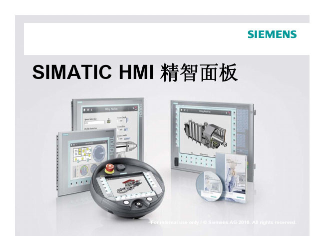
最新的例子是用于完成要求苛刻的可视化任务的 SIMATIC HMI 精智面板。
这些操作员面板不仅有创新设计,而且具有高性能。
它的独特之处是可通过 SIMATIC WinCC V11 进行组态。
该软件是“TIA 博途”这一全新工程软件平台的组成部分,支持以前从未有过的能效管理。
集成功能跨越所有显示尺寸SIMATIC 面板产品系列具有清晰的结构,两个设备系列涵盖了绝大多数人机界面应用:• SIMATIC HMI 精简面板适用于简单人机界面应用。
• SIMATIC HMI 精智面板适用于复杂应用。
同一系列中操作屏的硬件功能完全相同。
您可针对特定应用来选择最佳显示尺寸,并决定是通过触摸屏还是通过按键屏来实现操作任务。
您可以对软件进行扩展,以适应人机界面或 SCADA 解决方案,满足相应自动化任务的要求。
其优点是,您能够从较小的规模开始,并随时增加变量数目,而不会带来任何问题。
移动式操作员控制与监视 — 通过无线方式,具有全集成的安全功能对于在工厂中非常昂贵或难于观察的装置,便携式操作员面板显示出其优点:调试工程师、机器操作员或维修人员可在他们能够最佳观察工件或过程的位置工作。
SIMATIC HMI 移动面板分有线和无线两种版本。
无线移动面板通过无线工业以太网实现全集成安全功能,而此前该功能只支持有线移动面板。
支持独一无二的高效率使用 SIMATIC WinCC V11,可直观地对 SIMATIC 面板进行组态。
通过将 WinCC V11 集成到“TIA 博途”这一全集成自动化共享工程框架中,并使用 SIMATIC 控制器这样的全集成自动化组件,以实现效率的提高。
与 STEP 7 的完美协同可防止数据的多重输入,并始终确保数据管理的一致性。

SIMATICS7-PDIAG V5.7, Tool for Configuring the ProcessDiagnosticsSecurity InformationSiemens provides products and solutions with industrial security functions thatsupport the secure operation of plants, systems, machines and networks.In order to protect plants, systems, machines and networks against cyber threats, it is necessary to implement - and continuously maintain - a holistic, state-of-the-art industrial security concept. Siemens’ products and solutions constitute one element of such a concept.Customers are responsible for preventing unauthorized access to their plants,systems, machines and networks. Such systems, machines and componentsshould only be connected to an enterprise network or the internet if and to theextent such a connection is necessary and only when appropriate securitymeasures (e.g. firewalls and/or network segmentation) are in place.For additional information on industrial security measures that may beimplemented, please visithttps:///industrialsecurity.Siemens’ products and solutions undergo continuous development to make them more secure. Siemens strongly recommends that product updates are applied as soon as they are available and that the latest product versions are used. Use of product versions that are no longer supported, and failure to apply the latestupdates may increase customer’s exposure to cyber threats.To stay informed about product updates, subscribe to the Siemens IndustrialSecurity RSS Feed underhttps:///industrialsecurity.Notes on Installation and UsageThe installation notes contain important information that you will require in order to install S7-PDIAG V5.7. Read these notes before installing the software.These notes should be considered more up-to-date than the information in other documents.Read the notes carefully, because they contain information on installing and using S7-PDIAG V5.7.Notes on Usage (Release Notes)These notes should be considered more up-to-date than the information in manuals and online helps.Please note that when printing the file that the borders for legal sized paper (DIN A4) in portrait format are set to about 25mm.ContentsContents1Contents of the Consignment2Hardware Requirements3Software Requirements3.1Operating Environment3.2Memory Requirements3.3Online Documentation3.4Upgrading an earlier version of S7-PDIAG3.4.1S7-PDIAG V5.7 Upgrade4Installation4.1Installing S7-PDIAG V5.74.2S7-PDIAG V5.7 License Key4.3Uninstalling S7-PDIAG V5.75New Features and Changes in the New Version6Notes on Configuring and Operating the Software6.1General Notes6.2S7-PDIAG V5.7 Technical Specifications6.2.1Released CPU Modules6.2.2Memory Requirement Estimation6.2.3Approximate Values of the Cycle Load6.2.4Number of Communication Nodes with Process Diagnostics6.3Libraries and Sample Projects6.4Notes on Working with S7-PDIAG6.4.1Address Priority6.4.2Virtual Unit Overview6.4.3Update Message Texts Using Symbol Table7Notes on Documentation7.1Help on S7-PDIAG7.2Printing the Help7.3Manual1 Contents of the ConsignmentThis DVD, part of the contents of the consignment, contains a complete version ofS7-PDIAG V5.7.This version is in 5 languages and can be run using the operating systems listedunder Chapter 3.1.S7-PDIAG V5.7 is supplied as a DVD in the content of consignment of a floating orupgrade license described below:S7-PDIAG V5.7, Floating LicenseOrder number: 6ES7840-0CC05-0YA5The following items are included in this package:• 1 DVD S7-PDIAG• 1 License key USB• 1 Certificate of LicenseS7-PDIAG Upgrade V5.7 (V5.3/V5.6 -> V5.7)Order number: 6ES7840-0CC05-0YE5The following items are included in this package:• 1 DVD S7-PDIAG• 1 License key USB• 1 Certificate of LicenseContents of the S7-PDIAG-DVD•S7-PDIAG V5.7•Product Notes: "S7-PDIAG-What's New.rtf"•"S7-PDIAG for S7-300 and S7-400 Configuring Process Diagnostics" for V5.3 Manual "Getting Started: First Steps with S7-PDIAG and ProAgent" Manual forV5.3The manuals are ready to install on the DVD.Important noteThe manuals are no longer updated. Please refer to the correspondingonline help for up-to-date information.2 Hardware RequirementsIn order to work with S7-PDIAG V5.7 you need a suitable programming device or asuitable PC. There are no special hardware requirements. Therefore, the minimumrequirements specific to the operating system apply. You can find theserequirements on the appropriate Microsoft websites.3 Software Requirements3.1 Operating EnvironmentOperating SystemsS7-PDIAG V5. 7 can be used with the following operating systems:•MS Windows 10 Pro and Enterprise (64-bit)•MS Windows Server 2016 (64-bit) (Standard Edition as work station computer)•MS Windows Server 2019 (64-bit) (Standard Edition as work station computer)S7-PDIAG has not been tested on any other operating systems; use at your ownrisk.Compatibility toolWith the compatibility tool, you can put together a compatible selection of softwareproducts or check existing configurations for compatibility. You can find thecompatibility tool at:https:///cs/ww/en/view/64847781STEP 7S7-PDIAG V5.7 runs on the STEP 7 basic package V5.7 (or higher).The hardware and software requirement for installing STEP 7 must be met (see theSTEP 7 readme file).Internet-ExplorerAll operating systems must be use MS Internet Explorer 6.0 (or higher).User RightsTo be able to work with S7-PDIAG in MS Windows 10/Server 2016/2019 you musthave logged on at least as the primary user. You must have administrator's rightsfor installing the S7-PDIAG software and also for setting up modules using the"Setting the PG/PC Interface" application.If S7-PDIAG is installed on an NTFS drive, the administrator has to grant all theprimary users working with S7-PDIAG full access to the S7-PDIAG installationdirectory. Use the "Security" tab for this. You can get to it via the Sharing andSecurity... menu command in the Windows Explorer context menu. If this tab isnot available under Windows, then you have to clear the "Simple File Sharing(recommended)" check box in the Windows Explorer via the Tools > Folderoptions... in the "View".If projects are saved on NTFS drives, all primary users have to be granted fullaccess.File systemsS7-PDIAG achieves a slightly lower performance when operating on a MSWindows NT file system (NTFS) as opposed to a FAT file system.3.2 Memory RequirementsS7-PDIAG Memory RequirementsDepending on the number of languages installed, S7-PDIAG V5.7 requiresapprox.24 MB and 26 MB of memory on your hard disk. The exact value alsodepends on your operating system and on the file system used on yourprogramming device/personal computer.3.3 Online DocumentationThe S7-PDIAG V5.7 online help is split into two sections.You can find notes on the current context in the same way as with the standardWindows help.The general section of the online help is based on the HTML format. You can findmore information on the structure of the documentation in Chapter 7 (in Notes onUsage) in the second half of this README file (S7-PDIAG-readme.rtf).3.4 Upgrading an earlier version of S7-PDIAG3.4.1 S7-PDIAG V5.7 UpgradeTo install the upgrade package, you require a valid license for S7-PDIAG V5.3 orV5.6.4 Installation4.1 Installing S7-PDIAG V5.7You can install S7-PDIAG V5.7 over a previously installed version of S7-PDIAGV5.6. You do not have to uninstall these versions of S7-PDIAG first.In order to obtain the optimum display of the information during the Setup, youshould set the color scheme in the control panel of your programmingdevice/personal computer to at least 65536 colors.Insert the S7-PDIAG-DVD in the drive. The setup program will guide you throughthe installation of S7-PDIAG. The setup program starts automatically after the S7-PDIAG-DVD has been inserted in the drive. If you have disabled this function onyour computer, start the setup program with MS Windows Explorer by double-clicking the SETUP.EXE program in the root directory.In the component selection box, select the components you want to install.These components will then be installed and entries will be made in MicrosoftWindows files.S7-PDIAG is automatically installed on the drive where STEP 7 is located.NoteS7-PDIAG registers itself in MS Windows system files. You cannot move orrename S7-PDIAG files or folders using Microsoft Windows utilities such as theExplorer or modify S7-PDIAG data in the Microsoft Windows registry. The programmay no longer run properly after such modifications.4.2 S7-PDIAG V5.7 License KeyBefore you can start working with S7-PDIAG, you have to transfer the license keyfrom the license key USB stick to the computer. There are two ways of doing this:•While you are installing S7-PDIAG, the Setup program displays a message if there is no suitable license key installed on your computer. You can thendecide whether you want the license key to be installed by the “Setup” programor whether you want to install the license key manually at a later time using the“Automation License Manager” program.•If the license key cannot be installed during setup, continue the Setup program without installing the license key. Install the license key after the S7-PDIAGinstallation via the Start menu (for example, Windows 7) Start > All Programs >Siemens Automation > Automation License Manager.The Automation License Manager has to be installed for the S7-PDIAG operation.NoteAs of S7-PDIAG V5.3 the license key can be installed on all local drives.The Automation License Manager prevents the authorizations and license keysfrom being installed on invalid drives or media such as RAM drives, diskettes orcompressed drives (i.e. DBLSPACE). If the drive in a device is reported as being a"removable medium" and not, as usual, as a "hard drive", it will be treated as aDVD, which means that no license keys may be installed on it.In the case of compressed drives, you can install the authorization on theassociated host drive.You absolutely have to follow the notes in the Automation License Manageralmreadme.rtf file on the S7-PDIAG Installation DVD.Hidden files are stored in the folder "<Drive, on which the authorization/license keyis installed>:\AX NF ZZ". These files and the folder must not be deleted, moved, orcopied. They contain data required for the authorization of your software.If you do not adhere to these guidelines, the authorization may be irretrievably lost.Notes on error-free use of the license keys•The License Key USB stick must not be read-only. Because the License Key USB stick is to be used without write protection, there is a danger that a viruscould be transferred from the hard disk to the USB stick. You should thereforerun a virus check on your PC or programming device every time you install orremove a license key.•If you use an optimizing program which enables you to move fixed blocks of memory, only use this option if you had previously moved the license key fromthe hard disk back to the License Key USB stick.•When you install a license key, a specially marked cluster appears on the target drive. Some test programs mark this cluster as "defective." Do not attempt torestore the defective cluster.•Do not forget to transfer the license key to the License Key USB stick before formatting, compressing, or restoring your hard disk or before installing a newoperating system.•If a backup copy of your hard disk contains copies of license keys, there is a danger that these copies may overwrite the valid installed license keys whenyou restore your backup data to the hard disk, thereby destroying the validlicense keys. To prevent a valid license key from being overwritten by a backupcopy, you must remove all license keys before you make a backup copy orexclude the license keys from the backup.Using the trial licenseIf there is no valid license key installed for S7-PDIAG V5.7, the default triallicensesupplied with S7-PDIAG is installed and used. This license key can be usedonly 21 days. With the first S7-PDIAG start without a valid license key, the triallicense is activated after confirmation.4.3 Uninstalling S7-PDIAG V5.7Software products must be removed according to Microsoft Windows conventions.Use the Microsoft Windows application "Add/Remove Programs" (in the taskbar inStart > Settings > Control Panel > Programs and Features) to remove yoursoftware package (for example, "SIMATIC S7-PDIAG V5.7").Alternatively, you can also uninstall using the setup program.These notes should be considered more up-to-date than the information inmanuals and online helps.5 New Features and Changes in the NewVersionWhat's New in Comparison to Version 5.6?Please read the "What's New" RTF file on S7-PDIAG found on the S7-PDIAGDVD.6 Notes on Configuring and Operating theSoftwareNotes on Usage (Release Notes)These notes should be considered more up-to-date than the information inmanuals and online helps.6.1 General NotesThe general notes on the STEP 7 V5.7 basic package and later are fully valid inconnection with S7-PDIAG.6.2 S7-PDIAG V5.7 Technical Specifications6.2.1 Released CPU ModulesYou require a S7-300/400/WinAC CPU with the message functions ALARM_S/ALARM_SQ (SFC 17/18) and ALARM_D/ALARM_DQ (SFC 107/108) to be able towork with S7-PDIAG.Please use the documentation to check the CPU you are using for the availabilityand specifications of ALARM_S/SQ and ALARM_D/DQ. S7-PDIAG requiresALARM_S or ALARM_SQ at least.6.2.2 Memory Requirement EstimationThe specified values are approximate values, they are dependent on thecomplexity of the networks to be monitored and on the monitoring logic.NoteYou cannot configure and use more than 10 groups because of the maximumblock size of 8 Kbytes with CPU 314/315.6.2.3 Approximate Values of the Cycle LoadYou will achieve a cycle load below 10ms with the number of monitoring givenbelow:•CPU 314/315: level monitoring with timer + 100 without timer•CPU 413/414: level monitoring with timer + 400 without timerIf you have configured groups, the cycle time per group will increase by•CPU 314/315: 1 ms•CPU 413/414: 0.6ms6.2.4 Number of Communication Nodes with Process DiagnosticsDepending on the CPU type, there are upper limits with the S7-CPUs as regardsthe nodes which can be logged on simultaneously for the message functions usedby S7-PDIAG.The possible number of communication nodes (OP / WinCC / PG) of the messagefunction ALARM_S / ALARM_SQ used by S7-PDIAG is determined by the CPUtype.Please check the number of communication nodes for S7 message functions inyour corresponding CPU documentation.6.3 Libraries and Sample ProjectsA library and a sample project are supplied with S7-PDIAG V5.7.These sample projects can be deleted in the SIMATIC Manager. To reinstall them,you have to run the S7-PDIAG V5.7 setup program again.NoteThe sample project and library shipped with S7-PDIAG V5.7 are always copiedwhen you install S7-PDIAG. If you have edited the standard sample projects, theywill be overwritten with the original examples if you reinstall S7-PDIAG V5.7.You should therefore make a copy of the standard examples before you makechanges to them and then make changes to the copy.6.4 Notes on Working with S7-PDIAG6.4.1 Address PriorityIf changes in symbols result in changes to process diagnosis data for which the setaddress priority is to be followed, then these changes will be made when a projectis opened with the application S7-PDIAG or when a block with diagnostic capabilityis opened in the LAD/FBD/STL editor.These changes are not made in the symbol editor.6.4.2 Virtual Unit OverviewIf the view "Virtual unit overview" is disabled, you will only be able to moveinstances to other groups via the Group.6.4.3 Update Message Texts Using Symbol TableIn S7-PDIAG a symbol name or comment is configured as a message. If themessage text is changed manually in the symbol table or automatically using amultilingual tool, the message text will have to be compared with the symbol table.To do this, the check box for "Update Message Texts Using Symbol Table" (menucommand Options > Customize, Compile tab) in S7-PDIAG has to be activated.The update will then be performed during the generation of the process diagnosticseither via Process Diagnostics> Compile or Process Diagnostics > Compilecompletely.The activation of the check box in the customize dialog and generation is onlypossible if S7-PDIAG is installed.7 Notes on DocumentationComprehensive documentation on S7-PDIAG is available to you in the online helpfor S7-PDIAG. You will find the S7-PDIAG "basic information" in the HTML-based"Help on S7-PDIAG".The basic information and the reference information are both available to you aselectronic manuals.This means that you have the choice between calling information exclusively fromthe online help or printing out individual chapters in order to read this informationlater on.7.1 Help on S7-PDIAGIn S7-PDIAG, you can activate the "Help on S7-PDIAG" via the menu commandHelp > Contents. The "Help on S7-PDIAG" conveys basic knowledge as toworking with the S7-PDIAG software. You have the following search options:•You can navigate through the contents using the configuration tasks to be performed as your guide,•You can use Index by searching for topics,•You can use Search by entering single termsYou can find information on the menu commands and dialogs used, as well as thekeyboard controls or other application-specific information in the online help for S7-PDIAG.All the jumps within the Help on S7-PDIAG are in blue. The color changes as soonas the jump is activated.You can also find the "Help on S7-PDIAG" and the S7-PDIAG glossary via thebuttons of the same name on the upper margin of the help window.You can find the help on the application using the menu commands: Help >Context-Sensitive Help, Help > Introduction, Help > Getting Started or byselecting an object and pressing the button F1.7.2 Printing the HelpThe print function is available for both the "Help S7-PDIAG" and the applicationhelp. The scope of the information printed varies depending on whether you haveselected a single topic or a whole book in the contents page.7.3 ManualThe manual for S7-PDIAG can be accessed at Start > All Programs >SiemensAutomation > …. It can be displayed and printed with a PDF reader.Keep in mind the form of the Start menu differs under the various operatingsystems.Due to the editorial deadline necessary in the creation of the product manuals,there may be an occasional slight difference between their content and that of theonline help.。

Basic Controller SIMATIC S7-1200Be flexible thanks to networking possibilities Unrestricted / © Siemens AG/s7-1200SIMATIC controllers set new automation scaleTrends Solutions…Ethernet-based field busIT functionality Increased functionality and designflexibilityIncreased Integrated functionalityOptimized usabilityEasy to manage, reduced complexityPROFINET I/O as a standard at all PLCse.g. web server on-board all PLCsFor the same priceMore interfaces, higher performance, memory …e.g. motion control functions / PID controller /Trace / high speed counterse.g. integrated system diagnostics, project upload Simplified commissioning (serial machine building) Reduced, optimized portfolioIncrease of system functionalityHighlight performance•PROFINET Master –decentralized Profinet architectures possible for I/O, HMI, drives, and other Profinet field devices. NO communication module required!•PROFIBUS Master & Slave –decentralized Profinet architectures possible for I/O, drives, and other Profinet devices, including integration into existing system networks.•AS-i Master –The new AS-i-Master is configured in full in the TIA Portal and a new AS-i network can be created very easily with just a few clicks. AS-i networks do not therefore require separate software!•CANopen Master –Enables connection with CANopen devices, as well as with devices running Transparent CAN 2.0A.Highlight performance•Modbus TCP –Enables communication with devices as Modbus master or slave. Only one TCP function block is required for this. •IO-Link Master –Fast and easy integration of the SIRIUS compact starter, M200D starter and SIRIUS soft starter for simple starter control.•GPRS/LTE module –Easy implementation for data recording and control of decentralized computer.•TCP/IP –Via the instructions for open communication you can communicate with other CPUs, other PCs and with devices that use TCP/IP communication protocols as standard. NO communication module required!SIMATIC S7-1200 in the TIA PortalHighlight performance•RS-485, RS-422 & RS-232 –The S7-1200 CPU supports point-to-point (PtP) communication for character-based serial protocols, and this provides maximum freedom and flexibility for the use of PtP communication instructions in the user program.•Modbus RTU –Using the Modbus instructions the Modbus master or slave is able to communicate with devices that use the Modbus RTU protocol.•USS –Using simple USS instructions you can control the operation of drives that support the USS (Universal Serial Interface) protocolS7-1200CPUSMCM CP SM 1278CB 1241 RS485SINAMICS V20USSMODBUS RTUModuleCommunicationCM 1241RS232serial CM 1241RS422/485serialCM 1243-2AS-i master CM 1242-5PROFIBUS DP slave CM 1243-5PROFIBUS DP masterCP 1242-7GPRS Mobile communications telecontrolCP 1243-7LTE Mobile communications telecontrolCP1243-1Ethernet VPN/Firewall, Telecontrol Ethernet (DNP3, IEC 60870)RF120C RFID 1 Reader port; RS422CM CANopenCANopen3rd party: HMS 021620-BS7-1200 integrated PROFINET (Ethernet) interface… with the STEP 7 software•CPU hardware configuration•Loading a project•Monitoring/amending runtime tags•Set runtime I/O statuses•Diagnostics information... with HMI panels•Data from or to the CPU•System diagnostics... from CPU to CPU•Open communication with T-block instructions•Supported protocols: TCP/IP, ISO on TCP, UDP, S7 Com. (PUT/GET)MRP -Media redundancy protocolBased on ring topology (IEC 61158-5-10)Max. 50 nodes in the ring•PROFINET IO-Controller•PROFINET IO-Devices•Components of the network infrastructure (IE switches) 200 ms reconfiguration timeCPU 1215/17 as MRP Client at least FW V4.1 Configuration and diagnostics in STEP7Industrial Ethernet PROFINET•Improved plant availability•More flexibility•Lower costs since less equipment required > V4.1< V4.2S7 routing•Enables a connection between different subnets • A SIMATIC S7-1200 station acts as an S7 router •Based on PROFINET•Actually only with CP 1243-1 at least V2.0 (6GK7243-1BX30-0XE0) andCPU FW V4.2192.168.0.1 192.168.0.3 177.168.0.1192.168.0.2S7 routedConnectionSubnet1Subnet 2CommunicationWebserverIntegrated Web server•Access to system and process reports as well as identification data •System diagnostics for all configured assemblies centrally anddecentralized•Communication diagnostics on parameters, statistics, connection status •Access to process data via tag tables and freely definable tag lists •Pages to be defined by the user•Firmware updateArchive•Access via Webserver using Filebrowser for reciprocal exchanges of data in .csv format•Logging of user-defined tagsStation webserverVarious types of communication access: CPU PN interface, CP 1243-7 LTE,CP1242-7 V2•Central access via CPU page independentlyof the interface•User is then able to browse to the CP-specific webpages from thereuniform, consistent webserverfor entireS7-1200 stationRemote access viaInternet/mobile communicationsPN accessPROFINET i-Device•Simple configuration of S7-1200 CPUsin a master/slave architecture through reading and writing the reciprocal I/O images•Connection of CPUs in different projects•NO PN-PN coupler required (transparent network)IO controllerCPU1IE / PROFINETIO deviceOperational systemApplication / userprogramIO process imageInputaddr.Outputaddr.Operational systemApplication / userprogramIO process imageInputaddr.Outputaddr.PROFINET IOIO controller 1IO device 2IE / PROFINETIO device 1IO device 3i-deviceSavings with costs / installation / wiring of additional hardwareCPU2•Access for up to 2 controllers on S7-1200 as i-device •Rapid exchange of data in real time between S7-1x00 CPUs•Incorporation of 3rd party controllers under PROFINETAs ofV4.1Shared I-DeviceSerial communication•ASCII protocol (character-based serial communication)uses STEP 7 PtP instructions•USS Drive protocol is programmed with STEP 7 USSlibrary instructions•MODBUS protocol is programmed with STEP 7MODBUS library instructions•3964R ProtokollRS232RS485/422USS drivesUpdate rate Array•Fixed update rate (as fast as possible)•Enable instructions in an interrupt alarm OB in order toset a user-defined update rate.Support for drives•Maximum 15 drives per CM (communication module) supported•Non support:•MM3 drives•Deregistration of missing drives•S7-1200 CPU up to 8 IO-Link master modules -centralized•Data rate COM1 (4.8 kbaud), COM2 (38.4 kbaud), COM3 (230.4 kbaud)•Standard IO Mode (SIO Mode)•up to 4 IO-Link devices (3 wire) or 4 standard actuators•Diagnostics configurable for each port •I&M identification•IO-Link parameter allocation with S7-PCT (Port Configuration Tool) V3.2IO-Link supportSM 1278 4xIO-Link master (6ES7 274-1XK30-0XA0)•Point-to-point connection, no bus system•Existing wiring topologies are retained•Standard sensor/actuator cable (three wires with one signal wire), unshielded, 20 m in length,no special-purpose cable / connector•Manufacturer-independent communication standard for the PNO•Non-stop consistent communication•Cyclical, bidirectional process data communication (typ.2 ms cycle)•Non-cyclical service data transmission betweensensors/actuators and the controller as required •Integrated differentiated diagnostics alarms• LinkSwitchingdevices<20 mControl cabinet<20 m3RA6compact starters3RA27function modules for feeders3UG4monitoring relays3RW40soft startersSIMATIC RF120C –Fast communication module for S7-1200RF120CInterface to the applicationInternal S7 busConnection technology S7-1200 setup technology; screw terminals for 24 V supply Interface to the reader RS422 incl. 24 Volt; up to 115.2 KBaud Connection technology Submin-D connectorRFID system RF200, RF300, RF600, MOBY D/U, MV400FB, driver Instructions: Read, Write, Read_EPC-Mem, Write_EPC-Mem, Set_Ant_RF300, Set_Ant_RF600, Reset_Reader; based on FB101Number of readers 1 per RF120C; 3 per S7-1200Degree of protection IP 20Dimensions (W x H x D)30 x 100 x 75•Level measurement in silos and bunkers •Plattform scales•Force and tension measurements •Typical industries: Food & Beverage,Chemicals, Cement, Aggregate•Legal for trade certificate according OIML-R76•CPU 1212C →up to two SIWAREX modules •CPU 1214C orhigher→up to eight SIWAREX modules •Full parameter access from the CPU via free downloadable function block →Complete commissioning andcalibration via CPU/HMISIWAREX WP231 –Basic applications•Up to eight parallel connected analog 350 Ohm load cells per SIWAREX (1mV/V, 2mV/V, 3mV/V or 4mV/V)• 1 SIWAREX = 1 scale• 4 digital inputs / 4 digital outputs • 1 analog output•Ethernet (Modbus TCP & SIWATOOL)•RS485 (Modbus RTU)SIWAREX WP241 –Belt weigherapplications•Belt scales (Cement-, Aggragate plants, Mines, Food & Beverage plants)•Weigh feeder applications (Food & Beverage, Chemical, Steel)•CPU 1212C →up to two SIWAREX modules •CPU 1214C or higher→up to eight SIWAREX modules •Full parameter access from the CPU via free downloadable function block →Complete commissioning andcalibration via CPU/HMI•Up to eight parallel connected analog 350 Ohm load cells per SIWAREX (1mV/V, 2mV/V, 3mV/V or 4mV/V)• 1 SIWAREX = 1 scale• 3 digital inputs / 4 digital outputs / 1 speed sensor input • 1 analog output•Ethernet (Modbus TCP & SIWATOOL)•RS485 (Modbus RTU)SIMATIC S7-1200SIWAREX WP251 –Dosing , Batching and Bagging applications•Dosing and batching scales (Chemical-, Food-, Pharma, Packaging industries)•Bagging machines (Bulk solids industries)•Eichfähig gemäß OIML-R51, R61 und R76•CPU 1212C →up to twoSIWAREX modules •CPU 1214C or higher→up to eight SIWAREX modules •Full parameter access from the CPU via free downloadable function block →Complete commissioning andcalibration via CPU/HMI•Up to eight parallel connected analog 350 Ohm load cells per SIWAREX (1mV/V, 2mV/V, 3mV/V or 4mV/V)• 1 SIWAREX = 1 scale• 4 digital inputs / 4 digital outputs • 1 analog output•Ethernet (Modbus TCP & SIWATOOL)•RS485 (Modbus RTU)•RS485 (Modbus RTU)•A CANopen connection to a S7-1200 systemenables integration between devices and the S7-1200 system •Up to 3 CANopen modules per S7-1200 CPU •Connection type to the CAN: 9-pin DSUB (male)•Up to 16 CANopen nodes per module•256 bytes each for inputs and outputs with the CANopen module•Can be integrated in the hardware catalog of the TIA Portal configuration suite •Ready-made function blocks for simple PLC programming available in the TIA Portal • LinkController Area Network CANopen 021620-BMODBUS communication•Use of a CM or CB 1241 module for serial communication•MODBUS instructions of the communication module for simplified MODBUS RTU operation.•MB_COMM_LOAD for basic initialization of the master and slave operation•MB_MASTER and MB_SLAVE for controlling the report and connection allocations•Modbus addressing supports a maximum of 247 slaves (slave numbers 1 to 247).•Maximum of 32 devices per segment in the Modbus network depending on the loading and drive functions of the RS485 interface•Repeater required if using more than 32 devices to extend to the next segment•Open User Communication MODBUS TCP instructions usethe PROFINET port integrated in the CPUOverview of CP 1243-1 product features•Single-width S7-1200 enclosure (30 x 110 x 75)•Temperature range in operation: -20°C to +70°C•Standard rail mounting•Diagnostic LEDs (overall status and detail)•Power supply using backplane bus•1 x Ethernet Port RJ45 (10/100 Mbit/s) for connectinga modem/router such as SCALANCE M•Integrated security functions (VPN and Firewall)•Integration to Scada Systems via Telecontrol Protokolls(DNP3, IEC 60870)Communication Processor for connecting S7-1200 to Ethernet network withadditional Interface and security features firewall and VPN. Integration toScada Systems via Telecontrol Protokolls (DNP3, IEC 60870, TelecontrolBasic).Overview of CP 1243-7 product features•1 connection to LTE (4G) mobile network(different versions for EU and North America)•Single-width S7-1200 enclosure (30 x 110 x 75)•Temperature range in operation from -20ºC to +70ºC•Standard rail mounting•Diagnostic LEDs (overall status and detail)•Integrated security functions (VPN and Firewall)•Access to the CPU Webserver•Email and SMS Alarms•Process Monitoring and Control via Cellular networkPROFIBUS DP-Master CM 1243-5•Connection for up to 16 DP slaves•PG/OP communication:up to 4 connection for HMI and 1 connection for PG •S7 communication:4 S7 connections to other S7 stations with PUT/GETPROFIBUS DP-Slave CM 1242-5•as an intelligent DP slave for communication for the S7-1200 with any other DP masterCommunication for S7-1200 CPUs according to PROFIBUS standard IEC61158/61784SIMATIC S7-1200PROFIBUS communication DP master CM 1243-5 and DP slave CM 1242-5Challenges need innovative answersIndividualization Globalization Production Logistics •Global alliance ofproduction and suppliers •New business modelsProduction•Customized mass production•Top quality at a competitive priceTime to Market New Technology•Critical to success inhighly competitive industries•Pressure on productivity increases, shortening time for new developmentSustainabilityEnergy Consumption•The efficient use of energy and environmentally safe materialsAlways the appropriate controller with comprehensive functionalities!Innovations across the entire automation life cycle!Engineered in TIA PortalSecurity IntegratedIntegrated system diagnosis Technology Integrated+Design and Handling+Safety IntegratedInnovative system functions for more productivity!Protecting intellectual property and investment Protecting against unauthorized project changesSecurity integratedFor Efficient fault analysis, Uniform display concept and reducing plant downtimesSystem DiagnosticsInvestment protection while replacing S7-1200 with S7-1500 thanks to compatibility of programsScalabilityUser-friendly products, high efficiency and a scalableproduct portfolioFeature / Function BenefitIntegrated PROFINET◆Web server for service-and diagnostic informationTechnology Integrated◆perfect integration of drives through motion control functionalities and PROFIdriveIntegrated Trace functionality◆Program-and application diagnostics at real-time for recognizing even sporadic problemsUse of all TIA Portal advantages◆Efficient programming, commissioning and service toolshighest engineering requirementsEasily adapted to suit your needsFeature / Function BenefitSystem ModularityModular board concept is integrated customization ◆Adding I/O without increasing theCPU footprintExtensive built-in hardwarecapabilitiesEthernet,analog in/out-puts, MC I/O, HSC I/O, SD memory ◆Reduced need for additionalspecialty modules,smaller footprintand lower costOne Engineering SoftwareOne user program for logic, HMI, networking & drives. ◆Reduced engineering time/cost, easier to maintain, easier to reuseSafety IntegratedOne Controller for fail-safe and standard-automation◆reduction of types-and components by single automation system for Standard and SafetyOne Controller for Standard andSafetyNewNewFeature / Function Benefit•Basic Controller with SafetyIntegrated•Connecting ext. devices viaPROFIsafe•CPU 1212CF◆•One Controller, one Network andone Engineering for standardand fail-safe automation tasks•Energy Meter ModuleSM1238 AI ◆•Central Measurement andHandling of energy data •MRP at 2 Port CPUs 1215 / 17as client (FW 4.2)•S7-Routing (FW 4.2)◆•Higher flexibility in network set-up (flexible topology) and highernetwork availability •Userdefined web pages as startpages (FW 4.2)◆•Individual and easy adaption of(CPU) web pages to applications•Backup / Restore with retaindata (FW 4.2)◆•Protection of data loss(incl actual process values)Easy PLC selection thanks to an optimized Portfolio2xTMCPU 1211C-1PN CPU 1212C-1PN CPU 1214C-1PN CPU 1215C-2PN CPU 1217C-2PN CPU 1212FC CPU 1214FC CPU 1215FCCSM PM 13x CM / CP22x I/Q 11x SB 1x CB 1x BBSM 1226 F-DO 2x Relay SM 1226F-DO 4 x 24 V DC SM 1226 F-DI 16 x 24 V DCMarienhöher Milchproduktion Agro Waldkirchen GmbH / Waldkirchen, Germany -S7-1200 and Energy Meter ModuleAllow internal balancingduring operation without high effort and cost1Efficient operation and cost optimization2ReliableSystem Protection3Transparency in energy consumption... through the acquisition of energy data in acompact solutionIncrease of energy efficiency ... through analysisof the reactive power consumptionGuaranteeing plant availability ... by monitoring the current peaksCPU 1212C with SM1238 Energy Meter ModuleCPU 1212C with SM1238 and visualization via KTP 400CPU 1212C with SM1238 and visualization via KTP 400ChallengePreviously Now -CPU 1212CJanitza UMG96SM 1238 Energy Meter -Basic Panel, KTP 400TIA Portal BasicProducts usedCustomer benefitsProducts/solution Energy data acquisition of direct marketing(butcher shop, diary, cheese factory, sales room), transparency and internal balancing in an agricultural enterprise End customer /F&BWaldkirchen/GermanyiProject informationSIMATIC Controller Get more Information…Always up-to-date!•interesting news from and about AS, such as product innovations, success news, best practice information etc.Newsletter/newsletter Detailed product information and related subjects!•Product Websites •Twitter, Youtube..Internet/S7-1200References CenterFrom customer to customer! •Customers gives account to there experiences using our Products for their applicationsGetting Started/automation-tasksEasy Introduction to the new SIMATIC controller generation!•Learn about the new possibilitiesand get to know the new Hardware even betterhttps:///referen zen/#language=enSubject to changes and errors. The information given in this document only contains general descriptions and/or performance features which maynot always specifically reflect those described, or which may undergo modification in the course of further development of the products. The requested performance features are binding only when they are expressly agreed upon in the concluded contract.All product designations, product names, etc. may contain trademarks or other rights of Siemens AG, its affiliated companies or third parties. Their unauthorized use may infringe the rights of the respective owner.。

u Excellent low-light performance (0.017 lx in color)uBuilt-in Intelligent Video Analytics to trigger relevant alerts and quickly retrieve datauIntelligent Dynamic Noise Reduction reducesbandwidth and storage requirements by up to 50%u Outstanding wide dynamic range (100 dB with IAE)uAuto back focus for fast installationThe DINION IP starlight 7000 HD camera provides clear images 24/7 – even at night or under low-light conditions.High sensitivity in color (0.017 lx) and monochrome mode (0.0057 lx) enables this camera to work with a minimum of ambient light. This exceptional light sensitivity combined with Content-Based Imaging Technology (CBIT) ensures crisp, clear, detailedimages in all lighting conditions. The camera can also provide up to 60 images per second.System overviewCompared to SD cameras, the DINION IPstarlight 7000 HD offers, at no higher cost, motorized autofocus, higher resolution, better sensitivity, higher frame rates, and improved picture quality, and is still more bandwidth-efficient. Video storage costs are significantly reduced.Hybrid operationA surge-protected analog video output allows full hybrid operation. This means that high resolution IP video streaming and an analog video output are available simultaneously. The hybrid functionality offers an easy migration path from legacy CCTV to a modern IP-based system.FunctionsExceptional low-light performanceThe latest sensor technology combined with thesophisticated noise suppression results in a sensitivity of 0.017 lx in color. The low-light performance is so good that the camera continues to provide excellent color performance even with a minimum of ambient light.The camera is a true day/night camera with a mechanical filter for truly outstanding nighttimeperformance (0.0057 lx in monochrome). The filter can be switched remotely, or automatically via a light level sensor or contact input.Content Based Imaging TechnologyContent Based Imaging Technology (CBIT) is used to radically improve image quality in all lighting conditions and to identify areas for enhancedprocessing. The camera examines the scene usingIntelligent Video Analytics and provides feedback to re-tune the image processing. This provides better detail in the areas that matter and better all-roundperformance. With IVA, the Intelligent Auto Exposure technology, for example, allows you to view moving objects in bright and dark areas of a scene.Intelligent Dynamic Noise Reduction reduces bandwidth and storage requirementsThe camera uses Intelligent Dynamic Noise Reduction which actively analyzes the contents of a scene and reduces noise artifacts accordingly.The low-noise image and the efficient H.264 compression technology provide clear images while reducing bandwidth and storage by up to 50% compared to other H.264 cameras. This results in reduced-bandwidth streams that still retain a high image quality and smooth motion. The camera provides the most usable image possible by cleverly optimizing the detail-to-bandwidth ratio.Area-based encodingArea-based encoding is another feature which reduces bandwidth. Compression parameters for up to eight user-definable regions can be set. This allows uninteresting regions to be highly compressed, leaving more bandwidth for important parts of the scene. The average typical optimized bandwidth in kbits/s for various image rates is shown in the table:Fast performanceThe 60 images-per-second mode provides for optimum performance in fast action scenes and is particularly suitable for casino and banking applications. Multiple streamsThe innovative multi-streaming feature delivers various H.264 streams together with an M‑JPEG stream. These streams facilitate bandwidth-efficient viewing and recording as well as integration with third-party video management systems.An upright mode can be selected for the second stream. In this mode an image of 400 x 720 (9:16 aspect ratio) is cropped from the full sensor image. When the scene to be monitored is suitable to this mode, the bandwidth and storage requirements are reduced.Regions of interest and E-PTZRegions of Interest (ROI) can be user defined. The remote E-PTZ (Electronic Pan, Tilt and Zoom) controls allow you to select specific areas of the parent image. These regions produce separate streams for remote viewing and recording. These streams, together with the main stream, allow the operator to separately monitor the most interesting part of a scene while still retaining situational awareness.Intelligent Tracking can follow objects within the defined regions of interest. Intelligent Tracking can autonomously detect and track moving objects or the user can click on an object which the tracker will then follow.Scene modesThe camera has a very intuitive user interface that allows fast and easy configuration. Nine configurable modes are provided with the best settings for a variety of applications. Different scene modes can be selected for day or night situations.•Indoor – general day-to-night changes in an indoorenvironment without sun highlights or street lighting effects.•Outdoor – general day-to-night changes in an outdoor environment with sun highlights and street lightingeffects.•Traffic – for monitoring traffic movement on roads or parking lots. It can also be used in industrialapplications where fast moving objects are to bemonitored. Motion artifacts are minimized.•Night-optimized – optimized for details in low lightenvironments.•Intelligent AE – optimized for scenes with fluctuating front and back light caused by sunlight or otherilluminated objects in the scene.•Vibrant – enhanced contrast, sharpness andsaturation.•Low bit rate – reduces bandwidth requirements.•Sports and gaming – high-speed capture, andimproved color rendition and sharpness.•Retail – improved color rendition and sharpness with reduced bandwidth requirements.Storage managementRecording management can be controlled by the Bosch Video Recording Manager (VRM) or the camera can use iSCSI targets directly without any recording software.Edge recordingInsert a memory card into the card slot to store up to 2 TB of local alarm recording. Pre-alarm recording in RAM reduces recording bandwidth on the network, and extends the effective life of the memory card. Video analyticsWith built-in video content analysis, the camera reinforces the Intelligence-at-the-Edge concept where edge devices become increasingly intelligent. The MOTION+ video motion analysis system that is built into all camera versions is the perfect solution for applications where standard video content analysis features are required.The IVA version of the camera uses the latest generation of the Bosch Intelligent Video Analysis (IVA) software. This IVA system is the guard-assistant system of choice when reliable indoor or outdoor video analytics is needed. The state-of-the-art system reliably detects, tracks, and analyzes moving objects while suppressing unwanted alarms from spurious sources in the image.The face detection feature detects faces in the scene and forwards a high quality JPEG image of the best shot of each face when the face disappears from the scene.Retrospective forensic search capabilities are available remotely from the web browser or theBosch Video Client.Cloud-based servicesThe camera supports time-based or alarm-based JPEG posting to four different accounts. These accounts can address FTP servers or cloud-based storage facilities (for example, Dropbox). Video clips or JPEG images can also be exported to these accounts.Alarms can be set up to trigger an e-mail or SMS notification so you are always aware of abnormal events.Access securityPassword protection with three levels and 802.1x authentication is supported. To secure Web browser access, use HTTPS with a SSL certificate stored in the camera.Complete viewing softwareThere are many ways to access the camera’s features: using a web browser, with the Bosch Video Management System, with the free-of-chargeBosch Video Client, with the video security mobile app, or via third-party software.Video security appThe Bosch video security mobile app has been developed to enable Anywhere access to HD surveillance images allowing you to view live images from any location. The app is designed to give you complete control of all your cameras, from panning and tilting to zoom and focus functions. It’s like taking your control room with you.This app, together with the separately available Bosch transcoder, will allow you to fully utilize our dynamic transcoding features so you can play back images even over low-bandwidth connections.System integrationThe camera conforms to the ONVIF Profile S, ONVIF Profile Q and ONVIF Profile G specifications. Compliance with these standards guarantees interoperability between network video products regardless of manufacturer.Third-party integrators can easily access the internal feature set of the camera for integration into large projects. Visit the Bosch Integration Partner Program (IPP) website () for more information.True day/night switchingThe camera incorporates mechanical filter technology for vivid daytime color and exceptional night-time imaging while maintaining sharp focus under all lighting conditions.Easy installationPower for the camera can be supplied via a Power-over-Ethernet compliant network cable connection. With this configuration, only a single cable connection is required to view, power, and control the camera. Using PoE makes installation easier and more cost-effective, as cameras do not require a local power source.The camera can also be supplied with power from+12 VDC/24 VAC power supplies. To increase system reliability, the camera can be simultaneously connected to both PoE and +12 VDC/24 VAC supplies. Additionally, uninterruptible power supplies (UPS) can be used, which will allow continuous operation, even during a power failure.The auto-focus lens wizard makes it easy for an installer to accurately focus the camera for both day and night operation. The wizard is activated from the web browser or from the on-board camera push button making it easy to choose the workflow that suits best. The automatic motorized back focus adjustment with 1:1 pixel mapping ensures the camera is always focused accurately.HD standardsComplies with the SMPTE 296M-2001 Standard in:–Resolution: 1280x720–Scan: Progressive–Color representation: complies with ITU-R BT.709–Aspect ratio: 16:9–Frame rate: 50 and 60 frames/sStandardsHowever, if the system in which this camera is used needs to comply with this standard, then any power supplies used must comply with this standard.Installation/configuration notes ControlsDimensionsParts includedTechnical specificationsSensitivity – (3200K, reflectivity 89%, 1/60 sec shutter time, F1.2,30IRE)Resolutions (H x V)Ordering informationDINION IP starlight 7000 HDHigh-performance IP box camera for intelligent HD surveillance in low light. Hybrid IP/analog; 720p60; PoE; IDNR ; ROI; day/night; H.264 quad-streaming; free viewing Apps; cloud services; audio/motion detection; MOTION+Order number NBN-71013-BDINION IP starlight 7000 HDHigh-performance IP box camera for intelligent HD surveillance in low light. Hybrid IP/analog; 720p60; PoE; IDNR; ROI; day/night; H.264 quad-streaming; free viewing Apps; cloud services; audio/motion detection; IVAOrder number NBN-71013-BAAccessoriesVarifocal SR Megapixel LensVarifocal SR megapixel IR corrected lens. 1/2.5" sensor; CS-mount; 4-pin SR-iris; 5 MP; 9 to 40 mm;F1.5 to F8Order number LVF-5005C-S0940Varifocal SR Megapixel LensVarifocal SR megapixel lens. 1/2" sensor; C-mount; 4-pin SR-iris; 3 MP; 3.8 to 13 mm; F1.4 to F8Order number LVF-5003N-S3813Varifocal SR Megapixel LensVarifocal SR megapixel IR corrected lens. 1/2.5" sensor; CS-mount; 4-pin SR-iris; 5 MP; 1.8 to 3 mm;F1.8 to F8Order number LVF-5005C-S1803Varifocal SR Megapixel LensVarifocal SR megapixel IR corrected lens.1/1.8” sensor; CS-mount; 4-pin SR-iris; 5MP; 4.1 to9 mm; F1.6 to F8Order number LVF-5005C-S4109Varifocal Megapixel LensVarifocal megapixel IR corrected lens. 1/1.8" sensor max; C-mount; 4-pin DC-iris; 5 MP; 12 to 50 mm; F1.6 to T360Order number LVF-5005N-S1250S1374 AdapterAdapter to convert C mount lens to CS mount camera Order number S1374UPA-2430-60 Power SupplyPower supply for camera. 120 VAC, 60 Hz; 24 VAC,30 VA OutOrder number UPA-2430-60UPA-2410-60 Power SupplyPower supply. 120 VAC, 60 Hz; 24 VAC, 10 VA Out Order number UPA-2410-60Monitor/DVR Cable SMB 0.3M0.3 m (1 ft) analog cable, SMB (female) to BNC (female) to connect camera to coaxial cableOrder number NBN-MCSMB-03MMonitor/DVR Cable SMB 3.0M3 m (9 ft) analog cable, SMB (female) to BNC (male) to connect camera to monitor or DVROrder number NBN-MCSMB-30MVIDEOJET XTC XF Video TranscoderHigh-performance video transcoder. H.264; CF card slot; ROI; max resolution 1080p; 2 channelsOrder number VJT-XTCXFMonitor/DVR Cable SMB 3.0M3 m (9 ft) analog cable, SMB (female) to BNC (male) to connect camera to monitor or DVROrder number NBN-MCSMB-30MNPD-5001-POE Midspan PoE InjectorPower-over-Ethernet midspan injector for use with PoE enabled cameras; 15.4 W, 1-portOrder number NPD-5001-POENPD-5004-POE Midspan PoE InjectorPower-over-Ethernet midspan injectors for use with PoE enabled cameras; 15.4 W, 4-portsOrder number NPD-5004-POERepresented by:North America:Europe, Middle East, Africa:Asia-Pacific:China:Latin America and Caribbean:Bosch Security Systems, Inc. 130 Perinton Parkway Fairport, New York, 14450, USA Phone: +1 800 289 0096 Fax: +1 585 223 9180***********************.com Bosch Security Systems B.V.P.O. Box 800025617 BA Eindhoven, The NetherlandsPhone: + 31 40 2577 284Fax: +31 40 2577 330******************************Robert Bosch (SEA) Pte Ltd, SecuritySystems11 Bishan Street 21Singapore 573943Phone: +65 6571 2808Fax: +65 6571 2699*****************************Bosch (Shanghai) Security Systems Ltd.203 Building, No. 333 Fuquan RoadNorth IBPChangning District, Shanghai200335 ChinaPhone +86 21 22181111Fax: +86 21 22182398Robert Bosch Ltda Security Systems DivisionVia Anhanguera, Km 98CEP 13065-900Campinas, Sao Paulo, BrazilPhone: +55 19 2103 2860Fax: +55 19 2103 2862*****************************© Bosch Security Systems 2016 | Data subject to change without notice 14148787083 | en, V15, 30. May 2016。
西门子目录表:安全注意事项...................................................................................................... 3 总体信息 ............................................................................................................4 关于产品责任的说明........................................................................................... 4 1 技术描述.................................................................................................. 5 1.1 应用领域.................................................................................................. 5 1.2 结构......................................................................................................... 5 1.3 系统配置.................................................................................................. 7 2 安装/组装............................................................................................... 10 2.1 安装....................................................................................................... 10 2.2 组装....................................................................................................... 13 2.3 拆卸....................................................................................................... 16 3 调试....................................................................................................... 17 4 维护....................................................................................................... 19 4.1 管理和维护............................................................................................. 19 4.2 故障查找................................................................................................ 19 5 技术数据................................................................................................ 22 5.1 功能数据................................................................................................ 22 5.2 单元型式................................................................................................ 25 5.3 防爆....................................................................................................... 25 5.4 电磁兼容性(EMC ).............................................................................. 26 5.5 尺寸....................................................................................................... 27 6订货数据 (34)安全注意事项危险意思是:如果未能采取相应的安全预防措施,将肯定会导致死亡、严重的人身伤害、或实质性的财产损失。
德国原装伯恩斯坦安全开关功能和特点:??1、当负荷超过动作电流时,自动切断电路;??2、自动切断电路后,面板指示灯亮,便于故障部位的判断;??3、排除故障后,按面板下方的红色按钮即可恢复正常供电;??4、因其它原因壳体温度达到90℃±10℃时,自动切断电源,可防止烧坏电器或引发火灾;??5、当负荷未超过动作电流时,能保持长时间供电(即基本功能);??6、外形尺寸、安装与普通开关/插座相同;未完全排除故障而强行复位供电,自动重复断电、报警;??7、有故障的电路切断后,不影响其他电路的工作。
德国原装伯恩斯坦安全开关定义:??1、提供插销式开关、安全磁开关、安全门锁开关、安全拉绳开关、紧急停止按钮、绞链连锁开关、安全使能开关、安全限位开关、防爆开关等??2、安全开关防尘防水,抗震性强,使用寿命长,适用于标准机械工程及卫生要求严格的领域。
??3、所有产品系列的安全开关均满足欧洲和美国安全标准,获得CE、BG、UL、TUV、CSA等国际认证。
??4、安全拉绳开关最远防护距离可达200m??5、具有可选指示灯,可带紧急停止按钮,??6、金属外壳,IP67防护等级??7、最多4NC安全输出,2NO辅助输出??8、使用寿命长达200万次??9、具有防爆拉绳开关,符合EN418标准并具有CE认证??10、采用独特的磁编码式传感器设计,双面工作??11、此传感器结合了多种磁感应元件,必须按照特定的顺序才能正确工作??12、不锈钢材料外壳可满足食品饮料行业卫生要求,??13、可选择125°C高温产品系列,使用寿命可达1000次??14、允许错位安装达10mm,??15、外形尺寸及接线方式多样化??16、最高可达IP68防护等级安全开关/插座独创线路终端一对一保护功能,将电流过载保护技术融入普通开关、插座中,具备温升感应、自动断电、报警、复位、转接、连接等功能。
既延长了供电线路使用寿命,杜绝了电气火灾的发生,同时,当用电发生异常时,只切断故障位置的电源,而不会影响其它电器的正常用电。
22.08.2014-03:51:57hDatasheet -BNS 250-12Z-2187Safety sensors /BNS 250Preferredtyp(Minor differences between the printed image and the original product may exist!)•thermoplastic enclosure •Small body•Concealed mounting possible •33mm x 25mm x 13mm •Long life•no mechanical wear•Insensitive to transverse misalignment •Insensitive to soiling •Individual contact outletOrdering detailsProduct type description BNS 250-12Z-2187Article number 101168734EAN code4030661224237ApprovalApprovalBG USA/CANClassificationStandardsEN ISO 13849-1B 10d Opener/Normally open contact (NC/NO)25.000.000-notice at max.20%contact load Mission time 20YearsnoticeGlobal PropertiesProduct nameBNS 250Standards IEC60947-5-3,BG-GS-ET-14Compliance with the Directives(Y/N)YesMaterials-Material of the housings Plastic,glass-fibre reinforced thermoplastic -Material of the cable mantle PVCCoding available(Y/N)YesMonitoring function of downstream devices(Y/N)NoPrerequisite evaluation unit YesRecommended safety-monitoring moduleRecommended actuator BPS250Mechanical dataDesign of electrical connection CableCable length1mConductors0,25mm²AWG-Number23mechanical installation conditions not flushActive area front sideEnsured switch distance ON4mmEnsured switch distance OFF14mmType of actuation MagnetDirection of motion head-on with regard to the active surface restistance to shock30g/11msResistance to vibration10…55Hz,Amplitude1mmAmbient conditionsAmbient temperature-Min.environmental temperature−25°C-Max.environmental temperature+70°CStorage and transport temperature-Min.Storage and transport temperature−25°C-Max.Storage and transport temperature+70°CProtection class IP67Electrical dataIntegrated Safety monitoring module available(Y/N)NoCross circuit/short circuit recognition possible(Y/N)YesVoltage type VDCSwitch frequency max.5HzSwitching voltage max.24VDCSwitching current max.100mASwitching capacity max.1WOutputsDesign of control output Other,Reed contaktsNumber of shutters1pieceNumber of openers2pieceElectrical data-Safety outputsNumber of secure semi-conductor outputs0pieceNumber of secure outputs with contact0pieceElectrical data-Diagnostic outputNumber of semi-conductor outputs with signaling function0pieceNumber of outputs with signaling function that already have a contact0pieceLED switching conditions displayLED switching conditions display(Y/N)NoATEXExplosion protection categories for gases NoneExplosion protected category for dusts NoneDimensionsDimensions of the sensor-Width of sensor33mm-Height of sensor25mm-Length of sensor13mmnoticeContact symbols shown for the closed condition of the guard device.The contact configuration for versions with or without LED is identical.Included in deliveryActuators must be ordered separately.DiagramNote Diagrampositive break NC contactactiveno activeNormally-open contactNormally-closed contactOrdering codeBNS250-(1)Z(2)-(3)(1)111Normally open contact(NO)/1Opener(NC)121Normally open contact(NO)/2Opener(NC)(2)without without LED switching conditions displayG with LED switching conditions display(3)2187Individual contact outlet(without LED switching conditions display) DocumentsOperating instructions and Declaration of conformity(en)519kB,15.02.2010Code:mrl_bns250-12z-2187_enOperating instructions and Declaration of conformity(pl)281kB,22.05.2012Code:mrl_bns250-12z-2187_plOperating instructions and Declaration of conformity(es)420kB,07.05.2010Code:mrl_bns250-12z-2187_esOperating instructions and Declaration of conformity(nl)416kB,06.05.2010Code:mrl_bns250-12z-2187_nlOperating instructions and Declaration of conformity(de)835kB,24.09.2010Code:mrl_bns250-12z-2187_deOperating instructions and Declaration of conformity(it)405kB,06.05.2010Code:mrl_bns250-12z-2187_itOperating instructions and Declaration of conformity(jp)498kB,05.07.2011Code:mrl_bns250-12z-2187_jpOperating instructions and Declaration of conformity(pt)280kB,22.05.2012Code:mrl_bns250-12z-2187_ptOperating instructions and Declaration of conformity(da)272kB,27.08.2012Code:mrl_bns250-12z-2187_daOperating instructions and Declaration of conformity(fr)427kB,06.05.2010Code:mrl_bns250-12z-2187_frImagesDimensional drawing(basic component)Characteristic curveSystem componentsActuator101120594-BPS250•thermoplastic enclosureAccessories101131223-SPACER BNS250•to mount the magnetic safety sensor and actuator on ferromagneticmaterial•Suitable for food processing industryK.A.Schmersal GmbH&Co.KG,Möddinghofe30,D-42279WuppertalThe data and values have been checked throroughly.Technical modifications and errors excepted.Generiert am22.08.2014-03:51:58h Kasbase2.2.18.F DBI。