ISM3028U系列产品规格书
- 格式:pdf
- 大小:1.66 MB
- 文档页数:7

SAM 3X8E Hirel Arm® Microcontroller for AerospaceKey FeaturesCore• Arm Cortex®-M3 rev 2.0 running up to 84 MHz, delivering 105 DMips• Thumb®-2 instruction set, three-stage pipeline• Hardware divide, single cycle 32-bit multiply• Enhanced system debug with extensive breakpoint and trace capabilitiesMemory• 512 Kbytes in dual bank of 256 Kbytes embedded Flash • 64 + 32 Kbytes of SRAM memories in dual bank• 16 Kbytes ROM with embedded bootloader routines (UART, USB) and IAP routines• Static Memory Controller (SMC): SRAM, NOR, NAND support Nand Flash controller with 4 Kbyte RAM buffer and ECCSystem• Embedded voltage regulator for single supply operation • Power-on-Reset (POR), Brown-out Detector (BOD) and Watchdog for safe reset• Quartz or ceramic resonator oscillators: 3 to 20 MHz main and optional low power 32.768 kHz for RTC or device clock • High precision 8/12 MHz factory trimmed internal RC oscil-lator with 4 MHz default frequency for fast device startup • Slow clock internal RC oscillator as permanent clock for device clock in low-power mode• 3.0V to 3.6V/84 MHz operating voltage and speed grade • Temperature: –40˚C to +105˚C• One PLL for device clock and one dedicated PLL for USB2.0 high-speed mini host/device• Up to 17 peripheral DMA (PDC) channels and 6-channel central DMA plus dedicated DMA for Ethernet MAC• Low-power modesSAM3X8ECortex®-M384 MHzMPU6 LayerAHB Matrix25 ch DMAConnectivity22System1.8V RegulatorPOR, BOD2 Xtal OSC,2 RC OSC, 2 PLLWDT, RTT, RTCTRNGMemory Control16 ch, 12-bit ADC2 ch, 12-bit DACTemperatureSensor8x PWM9x 32-bit TimersUp to 103 IOsThe Microchip name and logo and the Microchip logo are registered trademarks of Microchip Technology Incorporated in the U.S.A. and other countries. Arm and Cortex are registered trademarks of Arm Limited (or its subsidiaries) in the EU and other countries All other trademarks mentioned herein are property of their respective companies. © 2021, Microchip Technology Incorporated. All Rights Reserved. 7/21 DS00002753BSpace Environment• Full wafer loT traceability• 144-lead hermetic ceramic package• Space grade screening and qualification• Total ionizing dose: up to 30 KRad (Si), QML and ESCC • Heavy ions and Protons test• Single Event latch-up LET> 62 MeV.cm2/mg• SEU full characterization at 105°C for all functional blocks •Safety application noteSAM3X8E Developement Tools• Arduino Due Development Board: /• Atmel Studio and software package: Worldwide supportecosystem of industry-leading suppliers of development tools, real-time operating systems and middleware productsOther Aerospace Applications• Full wafer lot traceability • 144-lead plastic package• QML-N/AQEC/AEC-Q100 equivalent• Unitary burn-in and temperature cycling (opt.)• Neutrons Latch-up immune (opt.)• SEU full characterization (opt.)•Other aerospace applicationProduct Selection GuidePeripherals• Up to 4 USARTs (ISO7816, IrDA ®, Flow Control, SPI, Man-chester and LIN support) and one UART• 2 TWI (I 2C compatible), up to 4 SPIs, 1 SSC (I 2S), 1 HSMCI (SDIO/SD/MMC) with up to 2 slots• 9-channel 32-bit Timer Counter (TC) for capture, compare and PWM mode, quadrature decoder logic and 2-bit gray up/down counter for stepper motor•Up to 8-channel 16-bit PWM (PWMC) with complementary output, fault input, 12-bit dead time generator counter for motor control• 32-bit low-power Real-Time Timer (RTT) and low-power Real-Time Clock (RTC) with calendar and alarm features • 16-channel 12-bit 1 msps ADC with differential input mode and programmable gain stage • 2-channel 12-bit 1 msps DAC• Ethernet MAC 10/100 (EMAC) with dedicated DMA • 2 CAN controllers with 8, mailboxes•True Random Number Generator (TRNG)© ESA/ill./HUART Jacky。

yInternal SMD Constructiony UL 94V-0 Package Material y Temperature Performance -25] to +75]y Output 3.3, 5, 12, 15, {5, {12 and {15VDC y Input 5, 12 and 24VDCy Low Costy 3000VDC Isolation y Efficiency up to 79%Key Features1W, High Isolation SMD, Single & Dual Output DC/DC ConvertersMinmax's MSLU300 1W DC/DC's are in "gull-wing" SMT package. The series is designed to provide high levels of isolation 3000VDC. It consists of 21 models with input voltages of 5V,12V and 24VDC which offers standard output voltages of 3.3V, 5V, 12V, 15V, {5V, {12V and {15VDC for the choice.Their impressive guaranteed efficiencies enable all models to deliver their fully rated output power from -25] to +75] without heat sinking or forced-air cooling.The MSLU300 series is an excellent selection for a variety of applications including data communication equipments, distributed power systems, telecommunication equipments and industrial robot systems.The MSLU300 units are available in tape and reel package.Leadfree Reflow Solder Process as per IPC/JEDEC J-STD-020C peak temp. 245C/10 sec.Exceeding the absolute maximum ratings of the unit could cause damage.These are not continuous operating ratings.Free-Air ConvectionCoolingmW550---Internal Power Dissipation%95--Humidity ]300---Lead Temperature (1.5mm from case for 10 Sec.)]+125-25Storage Temperature VDC 30-0.724VDC Input Models]+90-25CaseOperating Temperature VDC 18-0.712VDC Input Models ]+75-25Ambient Operating Temperature VDC 9-0.75VDC Input Models Input Surge Voltage( 1000 mS )Unit Max.Min.Conditions ParameterUnit Max.Min.ParameterEnvironmental SpecificationsAbsolute Maximum RatingsREV:5 2009/01/20MINMAX179554{0.7{34{15MSLU32979553{0.8{42{12MSLU32873857{2{100{5MSLU326795531.56715MSLU3257955328412MSLU3247385742005MSLU322701085152603.324(21.6 ~ 26.4)MSLU321805106{0.7{34{15MSLU319805105{0.8{42{12MSLU318768110{2{100{5MSLU3168151031.56715MSLU31580510528412MSLU31476811042005MSLU3127310159852603.312(10.8 ~ 13.2)MSLU311807255{0.7{34{15MSLU309797255{0.8{42{12MSLU3087510267{2{100{5MSLU3068072511.56715MSLU30579725528412MSLU304751026742005MSLU30272103023852603.35(4.5 ~ 5.5)MSLU301% (Typ.)%(Max.)mA (Typ.)mA (Typ.)mA mA VDC VDC@Max. Load @No Load @Max. Load Min.Max.EfficiencyLoad RegulationInput CurrentOutput CurrentOutput VoltageInput VoltageModel NumberModel Selection Guide# For each outputuF2.22.2104.74.73333Maximum Capacitive Load Unit {15V #{12V #{5V #15V 12V 5V 3.3V Models by VoutCapacitive Load100mA Slow - Blow Type200mA Slow - Blow Type500mA Slow - Blow Type24V Input Models 12V Input Models 5V Input Models Input Fuse Selection GuideInput SpecificationsInternal CapacitorInput FilterA 0.3------All ModelsReverse Polarity Input Current 26.42421.624V Input Models13.21210.812V Input Models VDC 5.554.55V Input Models Input Voltage RangeUnitMax.Typ.Min.Model Parameter2MINMAX REV:5 2009/01/20M Hours------2MIL-HDBK-217F @ 25], Ground BenignMTBFKHz 15010050Switching Frequency pF 10060---100KHz,1VIsolation Capacitance G[------10500VDC Isolation Resistance VDC ------3300Flash Tested for 1 SecondIsolation Voltage Test VDC ------300060 SecondsIsolation Voltage Rated Unit Max.Typ.Min.Conditions ParameterGeneral Specifications0.5 Second Max.Output Short Circuit%/]{0.02{0.01---Temperature Coefficient mV rms 15------Ripple & Noise (20MHz)mV P-P 150------Over Line, Load & Temp.Ripple & Noise (20MHz)mV P-P 10075---Ripple & Noise (20MHz)%See Model Selection GuideIo=20% to 100%Load Regulation %{1.5{1.2---For Vin Change of 1%Line Regulation %{1.0{0.1---Dual Output, Balanced LoadsOutput Voltage Balance Unit Max.Typ.Min.ConditionsParameterOutput SpecificationsNotes :1. Specifications typical at Ta=+25], resistive load, nominal input voltage, rated output current unless otherwise noted.2. Ripple & Noise measurement bandwidth is 0-20 MHz.3. These power converters require a minimum output loading to maintain specified regulation.4. Operation under no-load conditions will not damage these modules; however, they may not meet all specifications listed.5. All DC/DC converters should be externally fused on the front end for protection.6. Other input and output voltage may be available, please contact factory.7. Specifications subject to change without notice.8. It is not recommended to use water-washing process on SMT units.Block DiagramDual OutputSingle OutputREV:5 2009/01/20MINMAX3Tolerance Envelopes Graph (All other Output)Tolerance Envelopes Graph (3.3V & 5V Output)4MINMAX REV:5 2009/01/20Test ConfigurationsPeak-to-Peak Output Noise Measurement TestUse a Cout 0.33uF ceramic capacitor.Scope measurement should be made by using a BNC socket, measurement bandwidth is 0-20 MHz. Position the load between 50 mm and 75 mm from the DC/DC Converter.Maximum Capacitive LoadThe MSLU300 series has limitation of maximum connected capacitance at the output.The power module may be operated in current limiting mode during start-up, affecting the ramp-up and the startup time.The maximum capacitance can be found in the data sheet.Input Source ImpedanceThe power module should be connected to a low ac-impedance input source. Highly inductive source impedances can affect the stability of the power module.In applications where power is supplied over long lines and output loading is high, it may be necessary to use a capacitor at the input to ensure startup.Capacitor mounted close to the power module helps ensure stability of the unit, it is recommended to use a good quality low Equivalent Series Resistance (ESR < 1.0[ at 100KHz) capacitor of a 2.2uF for the 5V input devices, a 1.0uF for the 12V input devices and a 0.47uF for the 24V devices.Output Ripple ReductionA good quality low ESR capacitor placed as close as practicable across the load will give the best ripple and noise performance.To reduce output ripple, it is recommended to use 1.0uF capacitors at the output.Thermal ConsiderationsMany conditions affect the thermal performance of the power module, such as orientation, airflow over the module and board spacing. To avoid exceeding the maximum temperature rating of the components inside the power module, the case temperature must be kept below 90°C.The derating curves are determined from measurements obtained in an experimental apparatus.REV:5 2009/01/20MINMAX5Top View ( 2.54 mm / 0.1 inch grids )Connecting Pin PatternsMechanical Dimensions{0.002{0.05Pin X.XXX{0.005X.XX{0.13X.XX{0.01X.X{0.25Inches Millimeters Tolerance NA : Not Available for Electrical ConnectionNANA12NA NA 11NA NA 10UL94V-0:Flammability+Vout +Vout 8NA NA 7 2g :Weight -Vout NA 6Common -Vout 5Non-Conductive Black Plastic :Case Material NA NA 3+Vin +Vin 20.64*0.31*0.30 inches -Vin -Vin 116.3*8.0*7.67 mm :Case SizeDual OutputSingle OutputPin Physical CharacteristicsPin Connections6MINMAX REV:5 2009/01/20。

Moxa EtherDevice SwitchEDS-205A/208A SeriesHardware Installation GuideFourth Edition, October 2009© 2009 Moxa Inc. All rights reserved.Reproduction without permission is prohibited.P/N: 1802002050023OverviewThe EDS-205A/208A series of industrial Ethernet switches are entry-level industrial 5 and 8-port Ethernet switches that support IEEE 802.3, IEEE 802.3u, and IEEE 802.3x with 10/100M, full/half-duplex, and MDI/MDIXauto-sensing.The EDS-205A/208A series provides 12/24/48 VDC (9.6 to 60VDC)/18 to 30 VAC redundant power inputs that can be connected simultaneously to a live AC/DC power source. The switches are available with a standard operating temperature range from -10 to 60°C, or with a wide operating temperature range from -40 to 75°C, and IP30 metal housing makes them rugged enoughfor any harsh industrial environment.To provide greater versatility for use with applications from different industries, the EDS-205A/208A also allow users to enable or disable broadcast storm protection with DIP switches on the outer panel.The EDS-205A/208A switches can be easily installed with DIN-Rail mounting as well as distribution boxes. The DIN-rail mounting capability and IP30 metal housing with LED indicators make the plug-and-play EDS-205A/208A switches reliable and easy to use.NOTE Throughout this Hardware Installation Guide, we use EDS as an abbreviation for Moxa EtherDevice Switch:EDS = Moxa EtherDevice SwitchPackage ChecklistYour EDS is shipped with the following items. If any of these items is missing or damaged, please contact your customer service representative for assistance. y Moxa EtherDevice™ Switchy Hardware Installation Guidey Moxa Product Warranty bookletFeaturesHigh Performance Network Switching Technologyy EDS-205A: 10/100BaseT(X) (RJ45), 100 BaseFX (SC/ST connector, multi/single-mode)y EDS-208A series: 10/100BaseT(X) (RJ45), 100 BaseFX (SC/ST connector, multi/single-mode)y10/100M, Full/Half-Duplex, MDI/MDIX auto-sensingy IEEE 802.3/802.3u/802.3xy Store and Forward switching process type, 1024 address entriesRugged Designy Redundant dual 12/24/48 VDC (9.6 to 60VDC) or 18 to 30 VAC at 47 to63 Hz power inputy Operating temperature range from -10 to 60°C,or extended operating temperature of -40 to 75°C for (-T) models.y IP30 metal housingy DIN-rail or panel mounting abilityPanel Layout of EDS-205A/208A (Standard)Top Panel ViewTop Panel ViewRear Panel View Rear Panel View2EDS-208A Front Panel View8EDS-205A Front Panel View7321412431. Grounding screw2.Terminal block for power input P1/P2 3. Heat dissipationorifices 4. DIP Switches 5. Power input P1 LED 6.Power input P2 LED 7. 10/100BaseT(X) Port8.TP port’s 10/100 Mbps LED 9. Model Name10. Screw hole for wallmounting kit 11. DIN-Rail KitTop Panel ViewRear Panel ViewFront Panel View23214Top Panel ViewRear Panel View Front Panel View321456256The appearance of EDS-205A-S-SC is identical to EDS-205A-M-SC.1. Grounding screw2.Terminal block for power input P1/P23. Heat dissipationorifices 4. DIP Switches 5.Power input P1 LED 6. Power input P2 LED 7. 10/100BaseT(X) Port8.TP port’s 10/100 Mbps LED 9. Model Name 10. 100BaseFX Port 11. FX port’s 100 MbpsLED12. Screw hole for wallmounting kit 13. DIN-Rail KitTop Panel ViewRear Panel ViewFront Panel ViewTop Panel View Rear Panel View Front Panel View11The appearance of EDS-208A-S-SC is identical to EDS-208A-M-SC.1. Grounding screw2.Terminal block for power input P1/P2 3. Heat dissipationorifices 4. DIP Switches5. Power input P1 LED6. Power input P2 LED7. 10/100BaseT(X) Port8.TP port’s 10/100 Mbps LED9. Model Name 10. 100BaseFX Port 11. FX port’s 100 MbpsLED12. Screw hole for wallmounting kit13. DIN-Rail KitPanel Layout of EDS-208A-MM-SC/STTop Panel ViewRear Panel ViewEDS-208A-MM-SC Front Panel ViewTop Panel View Rear Panel View EDS-208A-MM-STFront Panel View11NOTE:The appearance of EDS-208A-SS-SC is identical to EDS-208A-MM-SC.1. Grounding screw2.Terminal block for power input P1/P23. Heat dissipationorifices 4. DIP Switches5. Power input P1 LED6. Power input P2 LED7. 10/100BaseT(X) Port8.TP port’s 10/100 Mbps LED9. Model Name 10. 100BaseFX Port 11. FX port’s 100 MbpsLED12. Screw hole for wallmounting kit13. DIN-Rail KitMounting Dimensions (unit = mm)DIN-Rail MountingThe aluminum DIN-rail attachment plate should already be fixed to the back panel of the EDS when you take it out of the box. If you need to reattach the DIN-rail attachment plate, make sure the stiff metal spring is situated towards the top, as shown in the figures below.STEP 1:Insert the top of the DIN-Rail into the slot just below the stiff metal spring. STEP 2:The DIN-Rail attachment unit will snap into place as shown below.To remove the EDS from the DIN-Rail, simply reverse Steps 1 and 2 above.Wall Mounting (optional)For some applications, you will find it convenient to mount theSTEP 1: Remove thealuminum DIN-Railattachment plate from theEDS-205A/208A’s rearpanel, and then attach thewall mount plates as shownin the diagram at the right.⇒STEP 2:Mounting the EDS-205A/208A on the wall requires 4screws. Use the switch, with wall mount plates attached,as a guide to mark the correct locations of the 4 screws.The heads of the screws should be less than 6.0 mm indiameter, and the shafts should be less than 3.5 mm indiameter, as shown in the figure at the right.NOTE Before tightening the screws into the wall, make sure the screw head and shank size are suitable by inserting the screw into one ofthe keyhole-shaped apertures of the wall mounting plates.Do not screw the screws in completely—leave about 2 mm to allow room for sliding the wall mount panel between the wall and the screws.STEP 3:Once the screws are fixed on the wall, insert the four screw heads through the large parts of the keyhole-shaped apertures, and then slide theEDS-205A/208A downwards, as indicated. Tighten the four screws for added stability.⇒Wiring RequirementsYou should also pay attention to the following points:y Use separate paths to route wiring for power and devices. If power wiring and device wiring paths must cross, make sure the wires are perpendicular at the intersection point.NOTE: Do not run signal or communications wiring and power wiring in the same wire conduit. To avoid interference, wires with different signal characteristics should be routed separately.y You can use the type of signal transmitted through a wire to determine which wires should be kept separate. The rule of thumb is that wiring that shares similar electrical characteristics can be bundled together.y Keep input wiring and output wiring separated.y It is strongly advised that you label wiring to all devices in the system when necessary.Grounding the EtherDevice SwitchGrounding and wire routing help limit the effects of noise due toelectromagnetic interference (EMI). Run the ground connection from the ground screw to the grounding surface prior to connecting devices.Wiring the Redundant Power InputsThe top two contacts and the bottom two contacts of the 4-contact terminal block connector on the EDS’s top panel are used for the EDS’s two AC/DC inputs. Top and front views of one of the terminal block connectors are shown here.STEP 1: Insert the negative/positive AC/DC wires into the V-/V+ terminals.STEP 2: To keep the AC/DC wires from pulling loose, use a small flat-blade screwdriver to tighten the wire-clamp screws on the front of the terminal block connector.STEP 3: Insert the plastic terminal blockconnector prongs into the terminal block receptor, which is located on EDS’s top panel.Communication ConnectionsThe EDS-205A models have 4 or 5 10/100BaseT(X) Ethernet ports, and 1 or 0 (zero) 100 BaseFX multi/single-mode (SC/ST-type connector) fiber ports. The EDS-208A models have 6, 7 or 8 10/100BaseT(X) Ethernet ports, and 2, 1 or 0 (zero) 100 BaseFX multi/single-mode (SC/ST-type connector) fiber ports.10/100BaseT(X) Ethernet Port ConnectionThe 10/100BaseT(X) ports located on the EDS’s front panel are used to connect to Ethernet-enabled devices. Below we show pinouts for both MDI (NIC-type) ports and MDI-X (HUB/Switch-type) ports, and also show cable wiring diagrams for straight-through and cross-over Ethernet cables.MDI Port PinoutsMDI-X Port Pinouts 8-pin RJ45Pin Signal 1 Tx+ 2 Tx- 3 Rx+ 6 Rx-Pin Signal1 Rx+2 Rx-3 Tx+ 6 Tx-RJ45 (8-pin) to RJ45 (8-pin) Straight-Through Cable Wiring Switch Port RJ45ConnectorRJ45Connector Tx+Tx-Rx+Rx-NIC Port Cable Wiring 3 36 61 122Rx+Rx-Tx+Tx-RJ45 (8-pin) to RJ45 (8-pin) Cross-Over Cable Wiring Switch Port (NIC Port)RJ45Connector RJ45Connector Tx+Tx-Rx+Rx-(Rx+)(Rx-)(Tx+)(Tx-)(Tx+)(Tx-)(Rx+)(Rx-)Switch Port (NIC Port)Cable Wiring 3 1621 326Rx+Rx-Tx+Tx-100BaseFX Ethernet Port ConnectionThe concept behind the SC/ST port and cable is quite straightforward. Suppose you are connecting devices I and II; contrary to electrical signals, optical signals do not require a circuit in order to transmit data. Consequently, one of the optical lines is used to transmit data from device I to device II, and the other optical line is used transmit data from device II to device I, for full-duplex transmission.Remember to connect the Tx (transmit) port of device I to the Rx (receive) port of device II, and the Rx (receive) port of device I to the Tx (transmit) port of device II. If you make your own cable, we suggest labeling the two sides of the same line with the same letter (A-to-A and B-to-B, as shown below, or A1-to-A2 and B1-to-B2).SC-Port to SC-Port Cable WiringTxRxAABBCable WiringA A BBST-Port to ST-Port Cable WiringCable WiringA ABBRedundant Power InputsBoth power inputs can be connected simultaneously to live AC/DC power sources. If one power source fails, the other live source acts as a backup, and automatically supplies all of the EDS’s power needs.DIP Switch SettingsEDS-205A/208A DIP SwitchesThe default setting for each DIP Switch is OFF.The following table explains the effect of settingthe DIP Switches to the ON positions.DIP Switch Setting Description------ Serves no function (reserved for future use).ON Enables broadcast storm protectionBSPOFF Disables broadcast storm protectionLED IndicatorsThe front panel of the Moxa EtherDevice Switch contains several LED indicators. The function of each LED is described in the table below.LED Color State DescriptionOn Power is being supplied to power input P1.P1 AMBEROff Power is not being supplied to power inputP1.On Power is being supplied to power input P2.P2 AMBEROff Power is not being supplied to power inputP2.On TP port’s 10 Mbps link is active.10M YellowBlinking Data is being transmitted at 10 Mbps.Off TP Port’s 10 Mbps link is inactiveOn TP port’s 100 Mbps link is active.Blinking Data is being transmitted at 100 Mbps.100M GREENOff 100Base TP Port’s link is inactive. Auto MDI/MDI-X ConnectionThe Auto MDI/MDI-X function allows users to connect the EDS’s10/100BaseTX ports to any kind of Ethernet device, without needing to pay attention to the type of Ethernet cable being used for the connection. This means that you can use either a straight-through cable or cross-over cable to connect the EDS to Ethernet devices.Dual Speed Functionality and SwitchingThe Moxa EtherDevice Switch’s 10/100 Mbps switched RJ45 port auto negotiates with the connected device for the fastest data transmission rate supported by both devices. All models of Moxa EtherDevice Switch areplug-and-play devices, so that software configuration is not required at installation, or during maintenance. The half/full duplex mode for the switched RJ45 ports is user dependent and changes (by auto-negotiation) to full or half duplex, depending on which transmission speed is supported by the attached device.Switching, Filtering, and ForwardingEach time a packet arrives at one of the switched ports, a decision is made to either filter or forward the packet. Packets with source and destination addresses belonging to the same port segment will be filtered, constraining those packets to one port, and relieving the rest of the network from the need to process them. A packet with destination address on another port segment will be forwarded to the appropriate port, and will not be sent to ports where it is not needed. Packets that are used in maintaining the operation of the network (such as the occasional multi-cast packet) are forwarded to all ports. The EDS operates in the store-and-forward switching mode, which eliminates bad packets and enables peak performance to be achieved when there is heavy traffic on the network.Switching and Address LearningThe EDS has an address table that can hold up to 1024 addresses, which makesit suitable for use with large networks. The address tables are self-learning, sothat as nodes are added or removed, or moved from one segment to another, the EDS automatically keeps up with new node locations. An address-agingalgorithm causes the least-used addresses to be deleted in favor of newer, more frequently used addresses. To reset the address buffer, power down the unit andthen power it back up.Auto-Negotiation and Speed SensingAll of the EDS’s RJ45 Ethernet ports independently support auto-negotiationfor speeds in the 10BaseT and 100BaseTX modes, with operation according tothe IEEE 802.3u standard. This means that some nodes could be operating at10 Mbps, while at the same time, other nodes are operating at 100 Mbps.Auto-negotiation takes place when an RJ45 cable connection is made, and theneach time a LINK is enabled. The EDS advertises its capability for using either10 Mbps or 100 Mbps transmission speeds, with the device at the other end ofthe cable expected to advertise in a similar manner. Depending on what type of device is connected, this will result in agreement to operate at a speed of either10 Mbps or 100 Mbps. If an EDS RJ45 Ethernet port is connected to anon-negotiating device, it will default to 10 Mbps speed and half-duplex mode,as required by the IEEE 802.3u standard.SpecificationsTechnologyStandards IEEE 802.3 for 10BaseT,IEEE 802.3u for 100BaseT(X) and 100BaseFX,IEEE 802.3x for Flow ControlProcessing Type Store and ForwardFlow Control IEEE 802.3x flow control, back pressure flowcontrolInterfaceRJ45 Ports 10/100BaseT(X) auto negotiation speed, F/Hduplex mode, and auto MDI/MDI-X connectionFiber Ports 100BaseFX ports (SC/ST connector,multi/single-mode)LED Indicators P1, P2 (Power), 10/100M (TP port), and 100M(Fiber port)DIP Switch enable/disable broadcast storm protectionOptical Fiber100BaseFXMulti-mode Single-mode Wavelength 1300 nm 1310 nmMax. TX -10 dBm 0 dBmMin. TX -20 dBm -5 dBmRX Sensitivity -32 dBm -34 dBmLink Budget 12 dB 29 dB5 km aTypical Distance40 km c4 km bSaturation -6 dBm -3 dBming [50/125μm, 800 MHz*km] cableing [62.5/125μm, 500 MHz*km] cableing [9/125 μm, 3.5 PS/(nm*km)] cablePowerInput Voltage 12/24/48 VDC (9.6 to 60 VDC),18 to 30VAC (47 to 63 Hz)Input Current @ 24VDC 0.1 A (EDS-205A)0.11 A (EDS-205A-M/S)0.13 A (EDS-208A)0.17 A (EDS-208A-M/S)0.22 A (EDS-208A-MM/SS)Connection Removable 4-contact terminal block1.1 AOverload CurrentProtectionReverse Polarity Protection PresentPhysical CharacteristicsHousing IP30 protection, metal caseDimensions EDS-208A Series: 50 x 115 x 70 mmEDS-205A: 30 x 115 x 70 mmWeight EDS-208A Series: 275 gEDS-205A: 175 gInstallation DIN-Rail Mounting, Wall Mounting(with optional kit)Environmental LimitsOperating Temperature -10 to 60°C (14 to 140°F)-40 to 75°C (-40 to 167°F) for -T models Storage Temperature -40 to 85°C (-40 to 185°F)Ambient Relative Humidity5 to 95% (non-condensing)Regulatory ApprovalsSafety UL508 (pending)Hazardous Location UL/cUL Class I, Division 2, Groups A, B, C, andD; ATEX Class I, Zone 2, Ex nC nL IIC T4(Pending)EMI FCC Part 15, CISPR (EN55022) class AEMS EN61000-4-2 (ESD), Level 3EN61000-4-3 (RS), Level 3EN61000-4-4 (EFT), Level 3EN61000-4-5 (Surge), Level 3EN61000-4-6 (CS), Level 3EN61000-4-8EN61000-4-1160068-2-27Shock IEC60068-2-32Freefall IEC60068-2-6Vibration IECWARRANTY 5 yearsTechnical Support Contact Information /supportMoxa Americas:Toll-free: 1-888-669-2872 Tel: +1-714-528-6777 Fax: +1-714-528-6778 Moxa Europe:Tel: +49-89-3 70 03 99-0 Fax: +49-89-3 70 03 99-99Moxa Asia-Pacific:Tel: +886-2-8919-1230 Fax: +886-2-8919-1231 Moxa China (Beijing office):Tel: +86-10-6872-3959/60/61 Fax: +86-10-6872-3958。

P/N: 1802002080016*1802002080016*EDS-208 Series Quick Installation GuideMoxa EtherDevice SwitchVersion 5.2, January 2021Technical Support Contact Information/support2021 Moxa Inc. All rights reserved.OverviewThe EDS-208 series of Moxa EtherDevice™ Switches are entry-level8-port Ethernet Switches that provide a cost-effective solution for industrial Ethernet connections. EDS-208 provides a choice of 12 to 48 VDC power input. The switches can operate reliably in a temperature range of -10 to 60°C, and the rugged hardware design makes EDS-208 perfect for ensuring that your Ethernet equipment can be used in demanding industrial environments.Package ChecklistMoxa EDS-208 is shipped with the following items. If any of these items is missing or damaged, please contact your customer service representative for assistance.• 1 EDS-208 or EDS-208-M-SC or EDS-208-M-ST•Quick installation guide (printed)•Warranty cardFeaturesHigh Performance Network Switching Technology•10/100BaseT(X) (RJ45), 100BaseFX (SC/ST type, Multi-mode) •IEEE 802.3/802.3u/802.3x•Store and Forward switching process type, 1024 address entries Industrial Design•Operating temperature ranges from -10 to 60°C•Power inputs: 12 to 48 VDC•IP30, plastic case•DIN-Rail mounting abilityPanel Layout of EDS-2081.Heat dissipation orifices2.Terminal block for power inputand grounding3.Moxa Logo4.Power input LED5.10/100BaseT(X) Port6.TP port’s 100 Mbps LED7.TP port’s 10 Mbps LED8.DIN-Rail kitPanel Layout of EDS-208-M-SC/ST1.Heat dissipation orifices2.Terminal block for power inputand grounding3.Moxa Logo4.Power input LED5.10/100BaseT(X) Port6.TP port’s 100 Mbps LED7.TP port’s 10 Mbps LED8.FX port’s 100 Mbps LED9.100BaseFX Port10.DIN-Rail kitMounting Dimensions (unit = mm)DIN-Rail MountingThe plastic DIN-Rail attachment plate should already be fixed to the rear panel of EDS-208 when you take it out of the box. If you need to reattach the DIN-Rail attachment plate to EDS-208, make sure the DIN-Rail kit is situated towards the top, as shown in the figures below.STEP 1: Insert the top of the DIN-Rail into the slot. STEP 2:The DIN-Rail attachment unit will snap into place as shown below.To remove Moxa EDS-208 from theDIN-Rail, insert a flat-blade screwdriver horizontally into the DIN-Railkit under the EDS-208, and thenpull it upwards and releaseEDS-208 towards you away fromthe DIN-Rail.You may also take the following steps to remove the EDS-208 from the DIN-Rail.STEP 1: Press the middle of the flat side of the mounting kit as indicated. Pull the EDS-208 downwards.STEP 2:Release it towards you and away from the DIN-Rail.Wiring RequirementsYou should also pay attention to the following items:• Use separate paths to route wiring for power and devices. If powerwiring and device wiring paths must cross, make sure the wires are perpendicular at the intersection point.NOTE: Do not run signal or communications wiring and power wiring in the same wire conduit. To avoid interference, wires with different signal characteristics should be routed separately.• You can use the type of signal transmitted through a wire todetermine which wires should be kept separate. The rule of thumb is that wiring that shares similar electrical characteristics can bebundled together.• Keep input wiring and output wiring separated.•It is strongly advised that you label wiring to all devices in the system when necessary.Grounding EDS-208Grounding and wire routing help limit the effects ofnoise due to electromagnetic interference (EMI).Run the ground connection from the right mostcontact of the 3-contact terminal block to thegrounding surface prior to connecting devices.Wiring the Power InputsThe two left-most contacts of the 3-contact terminal block connector on EDS-208’s top panel are used for the DC input. Top and front views of one of the terminal block connectors are shown here.STEP 1: Insert the negative/positive DC wires intothe V-/V+ terminals.STEP 2: To keep the DC wires from pulling loose,use a small flat-blade screwdriver to tighten thewire-clamp screws on the front of the terminalblock connector.STEP 3: Insert the plastic terminal block connectorprongs into the terminal block receptor, which islocated on EDS’s top panel.Communication ConnectionsEDS-208 has 7 or 8 10/100BaseT(X) Ethernet ports, and 1 or 0 (zero) 100BaseFX (SC/ST-type connector) multi-mode fiber ports.10/100BaseT(X) Ethernet Port ConnectionThe 10/100BaseT(X) ports located on EDS-208’s front panel are used to connect to Ethernet-enabled devices.Below we show pinouts for both MDI (NIC-type) ports and MDI-X (HUB/Switch-type) ports, and also show cable wiring diagrams for straight-through and cross-over Ethernet cables.MDI Port PinoutsMDI-X Port Pinouts 8-pin RJ45 PinSignal 1Tx+ 2Tx- 3Rx+ 6 Rx- PinSignal 1Rx+ 2 Rx- 3 Tx+ 6 Tx-RJ45 (8-pin) to RJ45 (8-pin) Straight-Through Cable WiringRJ45 (8-pin) to RJ45 (8-pin) Cross-Over Cable Wiring100BaseFX Ethernet Port ConnectionThe concept behind the SC/ST port and cable is quite straightforward. Suppose you are connecting devices I and II. Contrary to electrical signals, optical signals do not require a circuit in order to transmit data.Consequently, one of the optical lines is used to transmit data from device I to device II, and the other optical line is used to transmit data from device II to device I, for full-duplex transmission.All you need to remember is to connect the Tx (transmit) port of device I to the Rx (receive) port of device II, and the Rx (receive) port of device I to the Tx (transmit) port of device II. If you make your own cable, we suggest labeling the two sides of the same line with the same letter (A-to-A and B-to-B, as shown below, or A1-to-A2 and B1-to-B2). SC-Port Pinouts SC-Port to SC-Port Cable WiringST-Port Pinouts ST-Port to ST-Port Cable WiringLED IndicatorsThe front panel of EDS-208 contains several LED indicators. The function of each LED is described in the table below.LED Color State DescriptionP AMBER OnPower is being supplied to the powerinputOffPower is not being supplied to thepower input10(TP) GREENOn TP port’s 10 Mbps link is active Blinking Data is being transmitted at 10 Mbps Off TP Port’s 10 Mbps link is inactive100(TP) GREENOn TP port’s 100 Mbps link is active BlinkingData is being transmitted at 100MbpsOff 100BaseTX Port’s link is inactive100M(FX) GREENOn FX port’s 100 Mbps link is active BlinkingData is being transmitted at 100MbpsOff 100BaseFX Port’s link is inactiveAuto MDI/MDI-X ConnectionThe Auto MDI/MDI-X function allows users to connect EDS-208’s10/100BaseTX ports to any kind of Ethernet device, regardless of how the Ethernet cable is wired. This means that you can use either astraight-through cable or cross-over cable to connect EDS-208 to Ethernet devices.Dual Speed Functionality and SwitchingEDS208’s 10/100 Mbps switched RJ45 port auto negotiates with the connected device for the fastest data transmission rate supported by both devices. All models of EDS-208 are plug-and-play devices, so that software configuration is not required at installation, or during maintenance. The half/full duplex mode for the switched RJ45 ports is user dependent and changes (by auto-negotiation) to full or half duplex, depending on which transmission speed is supported by the attached device.Switching, Filtering, and ForwardingEach time a packet arrives at one of the switched ports, a decision is made either to filter or to forward the packet. Packets with source and destination addresses belonging to the same port segment will be filtered, constraining those packets to one port, and relieving the rest of the network from the need to process them. A packet with destination address on another port segment will be forwarded to the appropriate port, and will not be sent to the other ports where it is not needed. Packets that are used in maintaining the operation of the network (such as the occasional multi-cast packet) are forwarded to all ports.EDS-208 operates in the store-and-forward switching mode, which eliminates bad packets and enables peak performance to be achieved when there is heavy traffic on the network.Switching and Address LearningEDS-208 has an address table that can hold up to 1,000 node addresses, which makes it suitable for use with large networks. The address tables are self-learning, so that as nodes are added or removed, or moved from one segment to another, EDS-208 automatically keeps up with new node locations. An address-aging algorithm causes the least-used addresses to be deleted in favor of newer, more frequently used addresses. To reset the address buffer, power down the unit and then power it back up. Auto-Negotiation and Speed SensingAll of EDS-208’s RJ45 Ethernet ports independently supportauto-negotiation for speeds in the 10BaseT and 100BaseTX modes, with operation according to the IEEE 802.3u standard. This means that some nodes could be operating at 10 Mbps, while at the same time, other nodes are operating at 100 Mbps.Auto-negotiation takes place when a “live” RJ45 cable is connected to the switch, and then each time a LINK is enabled. EDS-208 advertises its capability for using either 10 Mbps or 100 Mbps transmission speeds, with the device at the other end of the cable expected to similarly advertise. Depending on what type of device is connected, this will result in agreement to operate at a speed of either 10 Mbps or 100 Mbps.If an EDS-208 RJ45 Ethernet port is connected to a non-negotiating device, it will default to 10 Mbps speed and half-duplex mode, as required by the IEEE 802.3u standard.SpecificationsTechnologyStandards IEEE802.3, 802.3u, 802.3xProcessing Type Store and Forward, with IEEE802.3x fullduplex, non-blocking flow controlAddress Table Size 1,000 uni-cast addressesInterfaceRJ45 Ports 10/100BaseT(X) auto negotiation speed, F/Hduplex mode, and auto MDI/MDI-X connection Fiber Ports 100BaseFX ports (SC/ST connector)LED Indicators Power, 10/100 M (TP port), 100 M (FX port) PowerInput Voltage 12 to 48 VDCInput Current @ 24 VDC 0.07 A (EDS-208)0.1 A (EDS-208-M-SC/EDS-208-M-ST) Connection Removable 3-contact Terminal Block Overload CurrentPresentProtectionPresentReverse PolarityProtectionMechanicalCasing IP30 protection, plastic caseDimensions 40 x 109 x 95 mm (W x H x D)Weight 170 gInstallation DIN-RailEnvironmentOperating Temperature -10 to 60°C (14 to 140°F) Storage Temperature -40 to 70°C (-40 to 158°F)5 to 95% (non-condensing) Ambient RelativeHumidityRegulatory ApprovalsSafety UL 508EMI FCC Part 15, CISPR 32 class A EMS EN61000-4-2 (ESD),EN61000-4-3 (RS),EN61000-4-4 (EFT),EN61000-4-5 (Surge),EN61000-4-6 (CS)Shock IEC 60068-2-27Free Fall IEC 60068-2-32Vibration IEC 60068-2-6 WARRANTY 5 years。

lInstructions for Use: Flexible Inspection Scope Kit-USB Brand Name of ProductFlexible Inspection Scope Kit - USB Generic Name of ProductFlexible Inspection Scope Kit - USB Product Code Number(s)FIS-007U, FIS-007USK, FIS-007UB, CT-101, CT-102Intended UseFor visually inspecting items.Range of Applications for ProductEnhance visual inspection by providing lighted magnification, image capture and the option for documentation in hard-to-see crevices, channels, and lumens in areas of instruments that are not visible to the unaided eye.Key Specifications of Product Flexible Inspection Scope- FIS-007U∙CT-101 1.90 mm OD and 110 cm length∙CT-102 1.06 mm OD and 110 cm length∙Opticalo Resolution format:o CT-102 1.06 mm: 40,000 pixels (or 200- x 200 pixels)o CT-101 1.90 mm: 160,000 pixels (or 400- x 400 pixels)o Field of View: 120° in airo Angle of view: 0°USB Control Module: Control Module housing Camera processor and LEDillumination:∙Dimensions: 5.25- x 3.90- x 1.85 inches∙Weight: 1.20 pounds ∙Digital Inspection Scope Connection∙Illumination Control- LED in the Control Module∙Power Cycle∙USB Camera Cable∙Easily change from small and large diameter scopes.Light Settings:There are four light settings operated by one button.Blinking Light (Indicates transmitting video data):∙Splash proof (IPX5 Rating)∙No external power needed.Flexible Inspection Scope Software Requirements:∙Compatible with Windows 10 Operating systems.∙USB flash drive includes software.Unpacking Flexible Inspection Scope:Carefully inspect for shipping damage. If there is any damage contact the shipping carrier and Heatlhmarkcustomer service 800-521-6224 immediately.USB Control Module: (Fig. 1).1.Digital Inspection Scope Connection 2.Illumination Control 3.Power Cycle B (Type C) on the right side of the boxFigure 1Flexible Inspection Scope™: (Fig. 2).∙CT-101 1.90 mm O.D. and 110 cm length ∙CT-102 1.06 mm O.D. and 110 cm lengthLarge1.90 mmSmall 1.06 mmFigure 2Flexible Inspection Scope™ Features3214Light/Illumination Settings: (Fig. 3).∙Five (5) light settingso Light on control indicats setting levelo Fifth setting is OFF∙Press light button to advance to next setting.∙Fifth setting turns the light OFF.Figure 3Power Cycle ButtonPress button to RESET camera (Fig. 4).Figure 41.Flexible Inspection Scope™ Plug (Fig. 5).Contains camera video connection as well as LED Light for illumination.1Figure 52.Flexible Working Length (Fig. 6).The portion of the Flexible Inspection Scope™ that is inserted into an item during visual inspection.The measuring scale markings on the Flexible Working Length are in centimeters (accuracy = ± 0.5 cm)2Figure 63.Distal Camera (Fig. 7).Distal portion of Flexible Inspection Scope™ that contains the camera lens3Figure 7SOFTWARE INSTALLATION:Note: This section is done only once when connecting the scope to the computer for the first time.∙System Requirements: MS Windows 10∙Install the Flexible Inspection Scope™ Software from the USB flash drive on a computer.Note: If you have any IT policies that may block this installation, please contact your IT team to give access to Healthmark scope viewer to install.1. Insert the USB Flash drive into your computer, and double click on the Healthmark Scope Viewer installer package to begin installation.2. The “Welcome to the Healthmark Scope Viewer Setup Wizard” screen pops up. Click on Next.3. Select the first tab Typical or setup type of your choice, click Next.4. Click Install and wait for installation to complete.5. Click Finish.STARTING SOFTWARE & CONNECTING SCOPE TO PC:(Fig 8).1.Open the Windows PC viewer software.2.Connect the Control Module to PC using USB Cable.3.Plug the Flexible Inspection Scope into the Control Module.4.In the viewer software, click Settings and Select USB Video Device, click on the desiredresolution, select the preferred Video Output Format, and then Click OK.5.Press the Power Cycle Button.Figure 86.Now you can start using the scope.Verifing OperationFollowing the steps listed below will ensure the proper use and performance of the Flexible Inspection Scope™. The Flexile Inspection Scope™ can be checked for normal operation by connecting it as described in the Startup section of this IFU.Normal operation includes:∙An image appearing on your computer monitor or HDMI Monitor.∙ A blinking light on Control Module near the Power Cycle button that indicates the image feed is transmitting.∙White light emitting from the distal end of the Digital Inspection Scope.∙An LED light on the control module top panel that indicates the light intensity of the device. Using SoftwareHealthmark Scope Viewer Software (Fig. 9).1.Capture button: Captures a Reference Image and saves it to the Reference Image folder.2.Main Image Window: Displays the image from the camera.3.Reference Image Window: Displays a reference image.4.Clear Button: Removes the image from the Reference image window.5.Open Reference Image button: Allows selection of a reference image from the Reference Imagefolder.6.Settings Button: Click to select the video camera and resolution settings.7.File Location Button: Click to change location where captured images are being saved.8.File Location Window: Shows the file path where captured images are being saved currently.9.Capture Image Button: Captures images and adds them to the File Location selected by the user(as shown in the File Location Window).10.Capture Video button: Click to record video. Click again to stop recording video.11.File Prefix: Type in text that you would like included in the file name of Captured Images.Figure 9Selecting Video Device or CameraFollow the directions below to select the video device or camera used to capture images using the Flexible Inspection Scope™ Viewer Software. (Fig. 10).1.Click Settings button in the lower left of the Scope Viewer software to display a list of videodevices or cameras being detected by your computer2.Select a device for capturing images using the Scope Viewera.The example below shows a webcam and USB Video Device in the Settings box. Select theUSB Video Device for the Flexible Inspection Scope™.b.You can also select your preferred Video Output Format from the dropdown box3.Click OK to view the selected Video Device.231Figure 10Capturing Still PicturesFollow the instructions for capturing still pictures from the Main Image Window.Select the Capture Image button. (Fig. 11).Figure 11Note: When an image is captured, “Image Captured” in red text will flash on the lower portion of the screen and a new file will appear in the Files Location.Capturing Video ImagesFollow the instructions below for capturing video from the Main Image Window.1.Select the Capture Video Button (Fig. 12).Figure 122.When the video is recording “Recording…” in red text will appear toward the bottom of thesoftware window.3.To stop recording, click Stop Capture. (Fig. 13).Figure 13Setting File PrefixFollowing the steps below allows you to create a file prefix that will appear after the underscore of image file names save to the File Location specified by the user.1.Click in the field next to File Prefix.2.Enter the characters that you would like to be included in the file name. (Fig 14).Figure 14Setting Location for Saved FilesFollowing the steps below allows you to set the file location of saved images using the Scope Viewer software.1.Click the File Location button.2.Select the file location you want to save captured images. (Fig 15).Figure 15Displaying Reference ImageThere are two ways to display a still image in the Reference Image Window on the Scope Viewer software.1.To display an image currently being displayed in the Main Image Window, click the Capture button. Note: The images will be saved in a file folder titled Reference Images in the designated File Location that the user specified in the File Location field. (Fig. 16).Figure 162.To display a saved image in the Reference Image Window from your File Location:a.Click the Open Reference Image button (Fig. 16 above).b.Select the file you want to display (Fig. 17 below).c.Click the OK Button, to display the image in the Reference Image Window. (Fig. 17).Figure 17Switching to a Different Flexible Inspection Scope™ on the Control Module:1.Press the Power button on the Control Module once.2.Disconnect the current Flexible Inspection Scope from the Control Module.3.Repeat the steps in the “STARTING SOFTWARE & CONNECTING SCOPE TO PC” procedure.Inserting Scope in ItemFigure 1Rotating Device to Avoid ObstacleFigure 2 Performing InspectionWipe down the Flexible Inspection Scope™ with a compatible wipe. Follow the manufacturer’s (Mfr.’s)Instructions for Use (IFU) for appropriate wipe usage. Click here to see the Chemical Compatibility Chart(PDF) for approved cleaning.The Flexible Inspection Scope™ is made of the same material as other common endoscopes. Any wipe,solution, or low temperature (≤ 60 °C [140 °F]) method intended for the reprocessing of endoscopes is likelycompatible with the Generation II Flexible Inspection Scope™ Catheters if used according to the productlabeling.Solutions Containing (Flexible Inspection Scope Only)Alcohol Ethoxylates Neutral or Near-Neutral pH DetergentsEnzymatic Cleaning Solutions Enzymatic DetergentsSodium Borated, Decahydrate Tetrapotassium PyrophosphateFlexible Inspection Scope™ has a fluid ingress protection rating of IPX7 (Waterproof) and can withstandimmersion in fluid up to one (1)-meter in depth for up to 30 minutes.Control Module USB has a fluid ingress protection rating of IPX5 (Water resistant) and can withstand asustained, low pressure water jet spray for up to three minutes.For Thorough Cleaning: CablesFollow the cleaning agent Mfr.’s IFU.1.Unplug and disconnect all components from the Control box prior to cleaning.2.Do not submerge or soak the cable for disinfection (cable is not waterproof).3.Wipe thoroughly with non-linting wipe moistened with facility approved neutral detergent. Use theappropriate brushes with detergent solution to remove any residues from areas that cannot bereached with the wipes.For Thorough Cleaning: Control Module1.Unplug and disconnect all components from the Control box prior to cleaning.2.Do not submerge or soak the cable for disinfection (Control Box is not waterproof).3.Wipe thoroughly with non-linting wipe moistened with facility approved neutral detergent. Use theappropriate brushes with detergent solution to remove any residues from areas that cannot bereached with the wipes.Note: Do NOT soak. Control Module and cables are not waterproof and should not be immersed.N/ACleaning –AutomatedDisinfection Control Module and CablesThese may be cleaned with alcohol based disinfectant wipes.Compatible agents (wipes and solutions) for disinfecting Flexible Inspection Scope™ and ControlModule:∙Hydrogen peroxide∙Isopropyl alcohol (IPA)∙Sodium hypochlorite (Bleach)∙Ortho-phenylphenol∙Quaternary ammonium.High-Level Disinfection (Flexible Inspection Scope™ Only)∙Select only disinfecting solutions listed in the compatible disinfecting methods.∙Follow all recommendations regarding health-hazards, dispensing, measuring, and storage from the Mfr. of cleaning and disinfecting agents.∙Soak the Flexible Inspection Scope™ in selected disinfecting solution per Mfr.’s IFU.∙Rinse the Flexible Inspection Scope™ with critical (sterile) water, again, following the disinfecting solutions Mfr.’s instructions.Reprocessing Chemical Compatibility Chart (PDF): Click here.。
QUICK START GUIDEOverviewThe MT-2002 20.3” Modero G5 Panoramic Tabletop Touch Panel(FG5969-35) features the G5 Graphics Engine to provide fast and smoothanimations and transitions, as well as a Quad Core Processor.The MT-2002 features a panoramic capacitive multi-touch screen thatprovides users access to multiple applications with minimal navigation. Thedistinctive, low-profile design is engineered to sit perfectly on a table withoutobstructing views.Sleep buttonSleep buttonUSB Ports (2)Cable slotFIG. 1 MT-2002Product SpecificationsConnector LocationsTwo Type A USB ports are located on the rear right corner of the device (FIG. 2).Type A USB PortsSpeakerSleep buttonFIG. 2 MT-2002-REAR VIEWUSB peripherals (mouse, keyboard, etc.) may be connected to either of the twoUSB ports on the rear of the device.The power and Ethernet connectors, as well as an additional USB port arelocated on the bottom of the device (FIG. 3).The underside USB port, as well as the two rear USB ports, may be used with aflash drive for page transfers or firmware upgrades.EthernetType A USB Port12V ... Power PortFIG. 3 MT-2002 UNDERSIDE CONNECTORSThe MT-2002 does not have individual channels on the base of the deviceto allow passage of cables from underneath the base. Instead, it has one slot atthe base to allow options on cable configuration, with channels for securingpower and Ethernet cables (FIG. 4).FerriteTie-wrap channelsTie-wrapFIG. 4 TIE-WRAP FOR POWER CONNECTOR FERRITEEach channel side has slots for attaching tie-wraps to secure each cable. Theferrite on the power cable must be secured with the included tie-wrap duringinstallation to prevent the possibility of the panel not sitting flush on the table.Other cables may be secured with tie-wraps if desired, but this is not necessary.Wiring GuidelinesThe MT-2002 uses a 12V ... -compliant power supply to provide power tothe panel via the 2-pin 3.5 mm captive wire PWR connector.The incoming PWR and GND wires from the power supply must be connected tothe corresponding locations within the PWR connector.Note: Apply power to the panel only after installation is complete.Note: Connecting power to the MT-2002 should be done using the included2-pin 3.5mm captive wire connector included with the device. This connectoris retained within its port with locking screws instead of the pins on each side ofstandard captive wire connectors, and using force to insert a standard captivewire connector may damage the device.A V FOR AN IT WORLD®Wiring a Power ConnectionTo use the 2-pin 3.5 mm captive wire connector with a 12V ... -compliant power supply, the incoming PWR and GND wires from the external source must be connected to their corresponding locations on the connector (FIG. 5).The connector uses locking screws to insure a connection to the device, so make sure to insert and tighten the screws before applying power.PWR +Power SupplyTo the Touch PanelGND -FIG. 5 NETLINX POWER CONNECTOR WIRING DIAGRAM1. Insert the PWR and GND wires on the terminal end of the 2-pin 3.5 mm captive wire cable.Match the wiring locations of the +/- on both the power supply and the terminal connector. 2. Tighten the clamp to secure the two wires. Do not tighten the screws excessively; doing so may strip the threads and damage the connector. 3. Verify the connection of the 2-pin 3.5 mm captive wire to the external 12V ... -compliant power supply and apply power.Powering On/Off Modero G5 PanelsModero G5 touch panels may be powered on by touching and holding the Sleep button. To power off the panel, press and hold the Sleep button, and select Power Off on the on-screen menu (FIG. 6):FIG. 6 SLEEP BUTTON - PRESS AND HOLD TO ACCESS POWER OFF/SETTINGS OPTIONSConfiguration and ProgrammingModero G5 touch panels are equipped with a Settings menu that provides the ability to configure various features on the panels. To access the Settings menu,press and hold the Sleep button, and select Settings .Note: Information on the Settings menu, panel configuration, and programming is provided in the Modero G5 Programming Guide, available at .Setting the Panel’s Device Number and Device Name1. In the Settings menu, select NetLinx . This opens a password keypad.2. Enter the panel password into the keypad (the default is 1988) and select OK to access the NetLinx page.3. Press Device Number to open the NetLinx editing window.4. Enter a unique Device Number assignment for the panel and press OK .5. Enter a unique Device Name assignment for the panel and press OK .Configuring the Panel’s IP AddressThe first step is to configure the panel’s IP address. Note that this only configures the panel to communicate with a network; it is still necessary to connect to the NetLinx Master (see Connecting to a NetLinx Master below ).Network Communication via DHCP1. In the Ethernet page, press DHCP/Static field to open the DHCP/Static window. Note that DHCP is the default setting.2. Select Host Name , enter the new host name3. Press OK to save changes.Network Communication via Static Address1. In the Ethernet page, press DHCP/Static to open the DHCP/Static window.2. Select Static to open the Static IP window.3. Press any field to open a keypad or keyboard (depending on the field), and enter the appropriate network address information.4. Press OK to save your changes and return to the Ethernet page.Connecting to a NetLinx MasterTo establish the type of connection to make between the panel and the NetLinx Master:1. In the NetLinx page, press Mode to choose the connection mode (URL, Listen or Auto):2. If password security is enabled on the target Master, enter the Username and Password:a. Select Username to open the NetLinx window.b. Enter the Username and Password required by the Master.c. Press OK to save changes and return to the NetLinx page.Related Software and Additional Documentation (at )• Programming the Modero G5 touch panel requires the use of either Rapid Project Maker (RPM) or the latest version of Netlinx Studio and TPDesign5, both available to download at . Refer to the NetLinx Studio and TPDesign5 online help for information.• For information on designing touch panel pages intended to optimize the Modero G5 experience, refer to the G5 Considerations Guide.• For additional information on the MT-2002 panel, refer to the Modero G5 Touch Panel Instruction Manual .• For detailed information on the Settings menu as well programminginformation and instructions on upgrading firmware, refer to the Modero G5 Programming Guide .• Detailed specifications drawings for the MT-2002 are available to download from .© 2018 Harman. All rights reserved. Modero X and Modero X Series, AMX, AV FOR AN IT WORLD, and HARMAN, and their respective logos are registered trademarks of HARMAN. Oracle, Java and any other company or brand name referenced may be trademarks/registered trademarks of their respective companies. AMX does not assume responsibility for errors or omissions. AMX also reserves the right to alter specifications without prior notice at any time. The AMX Warranty and Return Policy and related documents can be viewed/downloaded at .3000 RESEARCH DRIVE, RICHARDSON, TX 75082 | 800.222.0193 | 469.624.8000 | +1.469.624.7400 | fax 469.624.7153AMX (UK) LTD, AMX by HARMAN - Auster Road, Clifton Moor , York, YO30 4GD United Kingdom • +44 1904-343-100 • /eu/LAST REVISED: 09/12/2018。
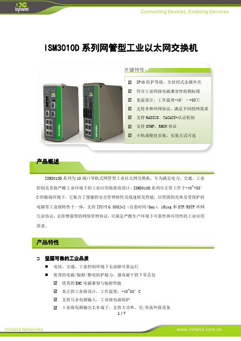
E22-900M30S产品规格书SX1262 868/915MHz 1W SPI LoRa无线模块第一章概述1.1 简介E22-900M30S是基于Semtech公司生产的全新一代LoRa TM射频芯片SX1262为核心自主研发的最大功率为1W并适用于868/915MHz贴片式LoRa TM无线模块,使用工业级高精度32MHz晶振。
由于采用原装进口的SX1268为模块核心,在原有基础上内置了功率放大器(PA)与低噪声放大器(LNA),使得最大发射功率达到1W的同时接收灵敏度也获得进一步的提升,在整体的通信稳定性上较没有功率放大器与低噪声放大器的产品大幅度提升。
与上一代LoRa TM收发器相比,抗干扰性能与通信距离得到了提升,进一步拉开了与FSK、GFSK调制方式的产品的差距。
该产品已获得FCC、CE、RoHS等国际权威认证报告,用户无需担忧其性能。
该产品可覆盖850~930MHz超宽适用频率范围并向下兼容SX1278、SX1276。
由于该模块是纯射频收发模块,需要使用MCU驱动或使用专用的SPI调试工具。
1.2 特点功能●与SX1276模块相比,SX1262模块具有功耗更低、速度更快、距离更远的显著优势;●理想条件下,通信距离可达12km;●内置PA+LNA,大幅度提升通信距离和通信稳定性;●最大发射功率1W,软件多级可调;●支持全球免许可ISM 868/915MHz频段;●LoRa TM模式下支持0.018k~62.5kbps的数据传输速率;●FSK模式下支持最高300kpbs的数据传输速率;●向下兼容SX1278/SX1276系列射频收发器;●FIFO容量大,支持256Byte数据缓存;●为支持密集网络推出的全新SF5扩频因子;●支持2.5~5.5V供电,大于5V供电均可保证最佳性能;●双天线可选(IPEX/邮票孔),便于用户二次开发,利于集成;1.3 应用场景●家庭安防报警及远程无钥匙进入;●智能家居以及工业传感器等;●无线报警安全系统;●楼宇自动化解决方案;●无线工业级遥控器;●医疗保健产品;●高级抄表架构(AMI);●汽车行业应用。
P R O F E S S I O N A LTECHNICAL DATAArenaMatch Utility AMU208small-format foreground/fill loudspeakerProduct OverviewBuilt for zone-fill coverage or high-SPL foreground music, Bose ArenaMatch Utility loudspeakers feature similar tonal balance to ArenaMatch array modules but in compactdesigns. They have the same EMB2S compression driver as ArenaMatch arrays, ensuring consistent sound, and the same IP55 weather rating. Deploy them for zone-fill coverage in sports stadiums, arenas, outdoor entertainment centers, and more. Or use them to provide intelligible, high-level sound in any outdoor area — from niche venues such as breweries and fairgrounds to larger settings like resorts and outdoor shopping centers.The AMU208 is a small-format ArenaMatch Utility model for outdoor applications that require excellent audio from a compact loudspeaker. It provides wide, even coverage with a 90° x 60° constant-directivity high-frequency horn, 70 Hz – 18 kHz frequency response, 126 dB peak SPL, and supports the lowest vocal ranges with two Bose LF8 8-inch woofers.Key FeaturesDeploy as zone-fill to support ArenaMatch arrays systems , delivering powerful, intelligible sound and ensuring consistent tonal balance with EMB2S compression drivers in every speaker Deploy to provide high-level foreground music in any outdoor venueInstall outdoors with an IP55 weather rating, three-layer stainless steel grille, water-resistant woofer cone coating, industrial polyurethane exterior coating, and molded cover to protect inputsAdapt to a variety of configurations — all models ship standard with 70/100V transformer inputs and passive crossover with optimized filters for more consistent frequency and polar responseStreamline the design process by combining with complementary Bose Professional products, such as PowerMatch amplifiers and ControlSpace DSPsMount easily with included stainless-steel U-bracket ; rear enclosure panel also includes M8 threaded inserts to accept third-party accessory mounting bracketsProvide wide, even coverage with 90° x 60° constant-directivity high-frequency horn, which can be rotated for horizontal or vertical installationPerform in the most demanding applications with 70 Hz – 18 kHz frequency response and 126 dB maximum peak SPL Support lowest vocal range with 2x Bose LF8 8-inch woofers featuring a 2-inch extended-excursion voice coil, which extends response to 70 HzFootnotes(1) Frequency response and range measured on-axis in anechoic environment with recommended bandpass and EQ. (2) Bose extended-lifecycle test using pink noise filtered to meet IEC268-5, 6-dB crest factor, 500-hour duration. (3) AES standard 2-hour duration with IEC system noise. (4) Sensitivity measured in anechoic environment with recommended bandpass and EQ. (5) Maximum SPL calculated using sensitivity and power ratings, exlusive of power compression.Technical SpecificationsFrequency ResponseFor additional specifications and application information, please visit . Specifications subject to change without notice. 03/2019。
BEFORE USE ....Thank you for choosing M-System. Before use, please check contents of the package you received as outlined below.If you have any problems or questions with the product, please contact M-System’s Sales Office or representatives.■PACKAGE INCLUDES:Signal conditioner (body + base socket) (1)■MODEL NO.Confirm M odel No. marking on the product to be exactly what you ordered.■INSTRUCTION MANUALThis manual describes necessary points of caution when you use this product, including installation, connection and basic maintenance procedures.POINTS OF CAUTION■POWER INPUT RATING & OPERATIONAL RANGE• Locate the power input rating marked on the product and confirm its operational range as indicated below:AC power: Rating ±10%, 50/60 ±2 Hz, approx. 2VADC power: Rating ±10%, approx. 2W■GENERAL PRECAUTIONS• Before you remove the unit from its base socket or mount it, turn off the power supply and input signal for safety.■ENVIRONMENT• Indoor use.• When heavy dust or metal particles are present in the air, install the unit inside proper housing with sufficient ventilation.• Do not install the unit where it is subjected to continuous vibration. Do not subject the unit to physical impact.• Environmental temperature must be within -5 to +55°C (23 to 131°F) with relative humidity within 30 to 90% RH in order to ensure adequate life span and operation.■WIRING• Do not install cables close to noise sources (relay drive cable, high frequency line, etc.).• Do not bind these cables together with those in which noises are present. Do not install them in the same duct.■AND ....• The unit is designed to function as soon as power is sup-plied, however, a warm up for 10 minutes is required for satisfying complete performance described in the data PONENT IDENTIFICATIONINSTALLATIONDetach the yellow clamps located at the top and bottom ofShape and size of the base socketare slightly different with varioussocket types.■DIN RAIL MOUNTINGSet the base socket so that itsDIN rail adaptor is at the bot-tom. Position the upper hookat the rear side of base socketon the DIN rail and push inthe lower. When removing therail adaptor utilizing a minusscrewdriver and pull.■WALL MOUNTINGRefer to “EXTERNAL DI-MENSIONS.”TERMINAL CONNECTIONSConnect the unit as in the diagram below or refer to the connection diagram on the front of the unit. ■EXTERNAL DIMENSIONS unit: mm (inch)CLAMP• When mounting, no extra space is needed between units.■CONNECTION DIAGRAM–U(+)V(–)CHECKING1) Terminal wiring: Check that all cables are correctly con-nected according to the connection diagram.2) Power input voltage: Check voltage across the terminal 7 – 8 with a multimeter.3) Input: Check voltage across the terminal 3 – 4 with a sensitive voltmeter (With 20°C or 68°F , approx. 220mV with Pt 100, approx. 110mV with Pt 50Ω). If RTD wires are broken, the output goes over 100% (be-low 0% with downscale) due to burnout function. Check leadwires in such a case.4) Output: Check that the load resistance meets the de-scribed specifications.ADJUSTMENT PROCEDUREThis unit is calibrated at the factory to meet the ordered specifications, therefore you usually do not need any cali-bration.The output signal can be finely adjusted to match it to a re-ceiving instrument, or to compensate input wire resistance when the unit is combined with a zenor barrier. Follow the regular calibration procedure explained below:■HOW TO CALIBRATE THE OUTPUT SIGNALUse a signal source and measuring instruments of sufficient accuracy level. Turn the power supply on and warm up for more than 10 minutes.1) ZERO: Apply 0% input and adjust output to 0%.2) SPAN: Apply 100% input and adjust output to 100%.3) Check ZERO adjustment again with 0% input.4) When ZERO value is changed, repeat the above proce-dure 1) – 3).MAINTENANCERegular calibration procedure is explained below:■CALIBRATIONWarm up the unit for at least 10 minutes. Apply 0%, 25%, 50%, 75% and 100% input signal. Check that the output signal for the respective input signal remains within accu-racy described in the data sheet. When the output is out of tolerance, recalibrate the unit according to the “ADJUST-MENT PROCEDURE” explained earlier.LIGHTNING SURGE PROTECTIONM -System offers a series of lightning surge protector for protection against induced lightning surges. Please contact M-System to choose appropriate models.KR / KRS。