ICS_2000软件说明书
- 格式:pdf
- 大小:769.52 KB
- 文档页数:45

ICS-2000操作规程正常操作步骤:一、仪器操作1.打开电脑电源、仪器电源、氮气瓶开关总阀,调整进淋洗液压力阀、进再生液压力阀压力分别为6psi、10psi;拔掉淋洗液罐密封塞;打开工作站界面;2.工作站与仪器“联机”;3.从功能泵(右)排气(排管路中空气):松开泵头,插入注射器,点淋洗液“开阀”。
无空气后关阀,扭紧泵头;4.从平衡泵(左)排气(排泵中空气):松开泵头,点“快速排气”,出现提示界面点确定,观察泵后排液管中气体是否排完,或约30秒后点“关泵”,扭紧泵头。
5.点“开泵”后完成以下设置:(阴罐编号:060951953015;阳罐编号:060952701028)5.1流速(阴0.5ml/min、阳1ml/min);5.2淋洗液浓度:阴:10mmol/L,阳20mmol/L,位置处于on;5.3捕获柱(CR-TC):位置处于on;5.4柱温度:35℃,池温:35℃;5.5抑制器类型;(阴ASRS-2mm;阳CSRS-4mm);5.6抑制器电流:(阴60mA,阳70 mA),在信号参数设置:阴:40mmol/L,阳20mmol/L;5.7抑制器开关:位置处于on;6.点采集开始,总电导维持在1.2左右,稳定后,小数点后两位基本不变。
稳定后记录泵压、总电导。
二、建立样品表和分析打开以前建立的样品表,另存为准备分析的样品表。
1、在浏览器界面的标样下添加样品测试数量及名称。
在“类型”下选择“标准”或“未知”。
回到控制界面。
2、关闭采集结束。
3.在批处理下选择编辑,选择所要测试的样品表,点“开始”。
3、准备好样品,开进样泵,检查是否有空气(打开泵上部出样阀)。
进样约一分钟后,关泵,点“确定”。
等待出峰,阴离子分析约需28分钟,阳离子分析约需约19分钟。
4、所有样品检测完后,进行数据处理。
4.1打开已完成的要处理的样品表,双击一个样品,进入处理界面。
在快捷栏中点“QNT编辑器”。
a.综合栏在综合栏中“数量量纲”下输入浓度单位;b. 检测栏在检测栏中优化积分:设置举例如下:c. 峰表在峰表中设置举例如下:d.数量表表格区域点右键选“列”→“编辑数量列”,出新界面,在“分配标准”下下拉选择“名称”,点“自动生成”,点“应用”,“确定”,分别输入各样品各离子的浓度,保存。


Badger Meter Europa GmbHiSonic 2000Intelligent ultrasonic meter and controllerPC Menu systemJuly 2002 (Applicable to iSonic Firmware revision 1.6)Content I1. Introduction (1)2. Run screens (2)3. Main menu (3)4. Configuration menu (4)5. I/O channels: Transducer menu (5)6. I/O channels: Process setup menu (6)7. I/O channels: Analog inputs (9)8. I/O channels: Relay (9)9. I/O channels: Digital inputs (11)10. I/O channels: Analog outputs (11)11. Logging, power and communications (13)12. Calibration (14)13. Tuning (15)14. Language selection (18)15. Change password (18)16. Special function setup (18)17. Total menu system (21)Introduction 1 / 231. IntroductionThe user-interface for the iSonic consists of a graphic LCD and a 6-key keyboard. With this interface, the user can configure the entire set-up of the instrument and select different information screens whilst the unit is in measurement mode.After a power-up, the iSonic will always start the measuring process, this is called RUN mode. When a user presses the “M” key on the keyboard, the unit will enter a configuration mode, this is called MENU mode.The interface for the user has been made to consistently work as follows:• The ‘M’ button either, when in RUN mode, calls up the menu, or, when in MENU mode, takes the user a menu level up.• The ‘OK’ button either starts the editing of a value or confirms a value. When editinga value, the ‘M’ key acts as a abort key, the value remains unchanged.•When editing a value, the Up and Down arrows (▲▼) either select options for that value (eg. ON/OFF), or for numeric values selects the next digit value.•When in menu selection mode the Up and Down arrows (▲▼) select the next menu entry.•When editing a value, the Left and Right arrows (◄►) either select options for that value (for instance: ON/OFF), or for numeric values select the digit next to the one currently selected.•When in MENU mode, the Left and Right arrows (◄►) select the next menu entry.The entire menu system is shown in the attached, “Appendix 2 – Total Menu System”Please note that the RUN mode is not always entered after a power-up; if unit has detected a faulty configuration, the MENU mode is automatically entered, requiring a user to configure the unit again.Not all configuration data is available through this interface, certain settings such as modem configuration, telephone numbers and the likes are only accessible through the PC configuration program. The LCD/Keyboard interface is mainly provided for quick field configuration changes and it is recommended to use the PC interface for initial configuration of a unit. The reasons for this is two fold:1. The PC configuration program is easier to work with and gives a morecomprehensive overview of a configuration.2. The PC configuration program performs numerous checks and does not allow invalidconfigurations. This is contrary to the menu system where a user is able to enter an invalid configuration. The iSonic does perform certain checks on the configuration but not all situations are tested.Run screens 2 / 23 2. Run screensThe first screen that is brought up by the unit combines most of the measurements that are being taken. It typically looks as follows:Other RUN screens can be selected by using the Up/Down and Left/Right keys. Available screens are:Either TRD 1 or TRD2 screen:All relevant information for the selected transducer, measured level, calculated units and a min - max bar graph:In the above screen, head is indicated in mm, also the process value is expressed in a percentage value. The application is a flow measurement, indicated in cubic feet per second. The minimum & maximum flow points (0% and 100%) are also indicated. The bottom of the screen shows the totaliser value for this channel.Main menu 3 / 23 Relay and Analogue Inputs screen:This screen shows the analogue inputs in mA and in percentage value. It also shows the complete status of each relay, whether it is ON (1) or OFF (0), the ON switch point and the OFF switch point, and what the current process value is. On the above screen, Relay4 is configured as a periodic timer and the ON and OFF time is shown in minutes.Bigger sized readout screen:Calculated measurement information only.This screen can be selected by pressing a “Right” or “Left” button.3. Main menuAny editing of the instrument’s settings can only be performed when the correct password is entered. To enter the MENU mode from the Run mode, press the ‘M’ button on the instrument. The following password screen will appear:At time of shipping, the password is set for “0000”. When the password screen is shown, the unit also displays the version number of the software and its serial number.If an incorrect password is entered at this stage the software will simply return to Run mode. Also, if nothing is entered for 15 seconds, the unit will automatically return to Run mode.Configuration menu 4 / 23 Once the password is correctly entered, the main menu navigation screen will appear:During menu navigating, a ‘>’ character on the left hand side of the screen will indicate at which menu entry the user is busy. Pressing the Up & Down arrow keys moves the selection indicator. To select a menu entry, press the ‘OK’ button.At an editable entry, when pressing the ‘OK” button, the indicator will change to a ‘∗’ character, showing that this entry is now being edited.The main menu entries perform the following functions:•Run; will start the measurement process again.•Configure; allows the user to configure the settings of the instrument (password protected)•Calibrate; allows the user to calibrate the measurements of the instrument (password protected).•Reset Output; allows the user to reset all the outputs.•Tune; is intended for measuring the echo manually, it is typically intended for use during an installation or during trouble shooting.•Language; allows the user to select a preferred interface language.•Change Password; here the user can configure a unique password setting.4. Configuration menuThe configuration menu is displayed as follows: ArrayWhere:•I/O channels; allows the user to enter the configuration for all the I/O signals.•Units; allows the user to configure the measurement units for the unit. Under thissub-menu one can set the temperature, level, flow and volume units. Also, it ispossible to configure the date & time format.I/O channels: Transducer menu 5 / 23 The iSonic supports:o Temperature: C°, F°o Level: mm, m, inch, fto Volume: m3, l, acft (Acre Feet), gal(USA), gal(UK), bbl (Barrel)o Flow: m3/s, m3/d, l/s, cfs, Mgd(USA), gpm(USA), Mgd(UK), gpm(UK)One special note on gallons; regardless of whether the user has selected US or UK gallons, the iSonic will display “gal” in its measurements, whilst using the correct conversion factor in its calculations.•Set Date/Time; configures the instrument’s internal clock. The screen shows the actual time and allows the user to change the settings.•Error delay; this factor determines how long the “last known good value” is held.•Log/Power/Comms; enters a sub-menu where the user can set Logging parameters, Low Power operation and communication parameters.•Factory Default; selecting this option resets all the parameters back to a factory default setting.When “drilling” one level down from I/O channels, the user is presented with the following screen:From this point onward, any I/O channel of the unit can be configured, using the appropriate type selection and index.5. I/O channels: Transducer menuThe configuration for a transducer is reached through the selection, “Configuration Æ I/O channels Æ Transducer”. Once the “Transducer” entry is reached, the screen will show “∗Transducer 1”, at that stage the user can select transducer 1 or 2 by pressing the Up Down arrows and then confirming by pressing “OK”.When selecting “Configuration Æ I/O channels Æ Transducer 1”, the user is presented with the following screen:Using this menu, the user can edit all the parameters for Transducer 1:• Whether it is active (On / Off)• The transducer’s active frequency, settable in kHz• Which type of measurement is being performed, this can be Level, Volume, Flow,Function or Sound. The “Function” entry indicates that a combination of 2 transducers is used where both their values are added, subtracted, averaged or used to calculate a differential flow. The “Sound” type can only be used on TRD2. Making this selection indicates that a special “Speed of Sound” transducer is connected on TRD2.• The filtering to be applied on the measurement, this can be; None, 16, 32, 64 and128. This value describes the number of samples that are taken to reach the measured value, “None” means that the directly measured value is used.• Deadband tells the instrument from which distance to start measuring.• Rate allows the configuration of the firing rate of the instrument. This can be fast,medium and slow. When a slow varying measurement is sought, select 128 averaging together with a “slow” repeat rate.• Process setup takes the user into the configuration for the actual process; this iswhere the measurement process can be described in detail.6. I/O channels: Process setup menuThe process setup menu is reached through the Transducer Menu. The sequence “Configuration Æ I/O channels Æ Transducer 1 Æ Process Menu”, produces the following display:The next screens from here on out are:The two limits for the level measurement are set here. The bar graphs, which are available in several RUN screens, are also configured with these limits. The units used in 0% and 100% are as selected in the “Units” set-up. If values are entered in ‘mm’ and at a later stage ‘inches’ are chosen the instrument will automatically perform the correctconversion.Level setupAgain, the 0% and 100% points can be programmed here, but in addition, the tank can be described as:• Vertical Cylinder (“Vert Cyl”)• Vertical Cylinder with a Bottom Cone (“V-Cyl +Cone”). The “X Dim:” value is used todescribe the height of the cone.• Horizontal Cylinder (“Hor Cyl”). This would typically be a vesel lying on its side, the “XDim:” value is used to indicate the horizontal length. • Sphere (“Sphere”) for a round tank.• Scaled (“Scaled”), where the vessel is calibrated in volume per head. Use the “Scale:”value to calibrate the reading.• Other (“Other”), selects the custom table values.After having made the proper tank type selection, the distance to Bottom, the Diameter, and other parameters can be filled.In addition to the 0% and 100% points, the user can select the following Weir & Flume types:• V-Notch weirs• Rectangular weirs with end contractions (“Contr. Rect.”) • Rectangular weirs without end contractions (“Suppr. Rect.”) • Trapezoidal weirs (“Cipolletti”) • Parshall flumes (“Parshall”)• Leopold-Lagco flumes (“Leopold-Lagco”)• Other, select this option to describe a non-standard weir or flume in the “CustomTable” which can be found under the “Process Setup” screen. This is a 15 segment user entered discharge table (flow vs. head)The “Weir size”, “Zero level” and “V-notch” parameters are used to describe the weir or flume in further detail.The “Units/tic” parameter is used in applications where an external totalising instrument is connected to one of the iSonic’s digital outputs. In the above example, the tick rate is 1 tick for every 1 cubic meter.Flow setupVolume setupAlarm setupIf an alarm is required for the relevant transducer (‘1’ in this screen), this is where to configure that alarm. Typically, the Alarm indicates an out-of-process value hence the “Alarm above” and “Alarm below” values. The setting is in percentages of the entire measurement range. The “Hysteresis” value avoids a jittery boundary effect, in this example the alarm will trip at 95% but will only reset once the process value reaches 93%. Similarly on the bottom value, the alarm trips at 5% but will only reset at 7%.The “Function” entry of the “Process Menu” can be a complex application to setup, please refer to the “Special Function Setup” appendix of this document for a more detailed description of the do’s and don’ts of this setting.This entry is only used if “Function” was chosen under “Transducer Menu ÆType”. Once this is done, iSonic is configured to make use of both transducers and perform one of the following functions:•Add, the values of both measurements are added together.•Subtract, the values of both measurements are subtracted as follows: “Measurement Value = Transducer1 – Transducer2”.•Average, the values of both measurements are averaged.•Differential Flow (“Diff Flow”). This is an application where 2 transducers are used to measure differential flow. Please refer to Appendix 1 for a more detailed description.Gain SetupThis screen allows the adjustment of gain over the total range of the returned echo signal. For each distance range a selection of gain can be made; None, Low, Medium or High. This is used when measuring difficult applications or tank environments where the default gain settings have to be adjusted in order to get proper signals.The last entry of the “Process Menu” is marked “Custom table”. This is used in certain instances of Volume & Flow applications. It is typically used in non-standard installations where the user describes a few known points and the system must interpolate between these points. Note that the custom table must be filled with consecutive values, starting from smallest head to biggest head. Please note that each transducer has its own table and not all table entries have to be filled.The first entry where the ‘Head’ value is zero, terminates the table.I/O channels: Analog inputs 9 / 237. I/O channels: Analog inputsSelecting the A/D inputs under “I/O Channels” presents the user with the following screen:The Analogue inputs can be:• Logged only•Used as an alarm input•Used as a control for a relays•Used as a control for the Analogue OutputsThe user can activate the input by selecting “Active: ON”. The type entry describes the nature of the external input, this can be either: a 4–20mA or a 0-5V signal.The “Alarm setup” is identical to the one that can be found under the transducer configuration screens. Please refer to that description for more details.8. I/O channels: RelaySelecting “Relay” under “I/O Channels” presents the user with:The user has full control over the behaviour of four of the five relays on the iSonic.The entries available are:•“In use:”, this is where the relay can be enabled and disabled•“Channel:”, this describes which measured value actually controls the selected relay. Options are:o TRD 1 for transducer 1o TRD 2 for transducer 2o A/D 1 for Analogue Input 1o A/D 2 for Analogue Input 2o None indicates that the relay is controlled only by a time value.•“On perc:”, indicates the percentage at which the relay should switch ON•“Off perc:”, indicates the percentage at which the relay should switch OFF.On and Off percentages can be programed in 0.1% unitsI/O channels: Relay 10 / 23 •“Rotate:”, enters this particular relay into the rotation list. This feature is used for pump control where several pumps need to be operated in an even wear mode.•“Timer:”, allows the user to select a number of options:o“Inactive”, the timer is not runningo“Daily”, the relay is switched ON at a certain time of the day and switched OFF again at another time.o“+Periodic”, in addition to the previous rule the relay is also switched at certain intervals.•“Setup Timer”, results in:These timer values are the parameters which are used for the behaviour as selected under “Timer:”. The periodic timer is programmable with a resolution of 0.01 minutes. Notes:• A relay can be controlled simultaneously by a measured value as well as a timer event. Note that the timer has higher priority.•If one wishes Periodic behaviour but no Daily event, simply make the “On time: and “Off time:” values zero.•If both daily timer and periodic timer have been enabled, the daily timer will have higher priority.•More than one relay can be controlled by the same transducer or analogue input. For instance one relay can be controlled in the range of 30 to 50% and another in the range of 10 to 70%.A few examples for relay set-ups follow:• A tank is filled with water from a borehole, and is discharged into a household. The rule is that the borehole pump should only run when the tank is emptied below 50% and also that the tank should never fill above 95%. In this case, set the ON percentage to 50% and the OFF percentage to 95%. As soon as the tank empties below 50%, the relay (pump) will activate and will only de-activate when the measured level/volume is above 95%.• A stream empties into a holding tank for further distribution into a network, the network is only allowed to take water when enough supply is available (Tank above 50%), when the tank reaches a critical level (10%) a valve shuts off the outflow. In this case, set the ON percentage to 50% and the OFF percentage to 10%. The valve will open once the measured level/volume is above 50% and will only close once the process reaches 10% or less.Other combinations of the above are also possible. With the Normally Open and Normally Closed contacts being available, other logical combinations can be made.9. I/O channels: Digital inputsSelecting “Digital In” under “I/O Channels” presents the user with:The “Type” tells the iSonic what the usage of this particular input is, it can be either a control input or a pulse output from, say, a water meter.When configured as a control type, the input functions as a trip alarm. Digital Inputs can only be used to de-activate a condition. If a relay is activated by a measurement or timer it can be “tripped” (deactivated) by the digital input.One application could be a safety switch, which measures near the top of a tank. Even if the transducer measurement fails, overfilling is avoided because of the digital input. The “Scale” and “Window” parameters are used in a situation where the digital input is configured as a counter. The scale selects the unit increment per pulse and window selects the length of the logging window. At the start of a window period the count value is zeroed automatically.As an example:The iSonic has been set up to perform cubic meter measurements. An external water meter generates a pulse for every 10 litres of water (0.01m3). The user wants a data log of cubic meters per minute.In this case, configure the “Scale” as 0.01 and the “Window” as 60 seconds. The data-log will reflect a cubic meter reading every one minute.10. I/O channels: Analog outputsSelecting “Analog Out” under “I/O Channels” presents the user with:Here the two analogue outputs of the unit can be programmed.“Channel” selects which input process value controls the behaviour of this particular analogue output. The user can select the following channels; Transducer 1 & 2 and Analogue Inputs 1 & 2.The “Type” option selects whether the unit should re-transmit the current as measured by either transducers or analogue inputs, or whether a “Control” type action should be performed.The 4 and 20mA points can be programmed for any percentage of the process value of the relevant channel. The unit will linearly interpolate the output current between the two set points. If for example the percentages are set for 90% and 10% then for any PV value >90% the unit will maintain 4mA and for any PV value <10% the unit will maintain 20mA.The “Error mA” setting allows for the programming of an error current to be output when the input values are improper or out of range.When selecting “Setup Control”, the following screen appears:Please note that this screen is only valid when the “Type” selection was “Control”.In this section the PID parameters can be set , using these settings a PID regulation process kicks in action where the channel’s output current is set in response to changes in the process value. The instrument will attempt to control the process in such a way that the required setpoint is always correct. The controlling “Action” can be set to be “Direct” or “Reverse” indicating whether the response should be normal or inverse to the measured error. The PID values can all be individually set by the user to tune the process to the required response speed and stability. For more details on PID refer to a PID handbook or access the Internet, many useful tutorials are freely available.The "Deadband" setting defines the area around the Setpoint where the output is kept constant. When regulating from outside the deadband the output is only made constant after the input has crossed the Setpoint. (Known as zero-crossing).For instance, if the “Setpoint” is set for 30% and the “Deadband” is set for 1%, then the output will not change for process values between 31% - 29%. This deadband value can be made as small or as big as the process demands, it entirely depends on the required activity of the controlled device.The above described control section allows each output channel to control an individual output based on an individual input. In addition to this mode it is also possible to link both outputs to a single measured process. This is done by setting the “Linked” option to “Yes”. In this case the PID settings are taken from “DAC1”.This will result in both outputs being used to control a process, where the outputs mirror at the 4mA point. The entire regulation range can be graphically represented as follows:20mA20mA4mA4mA Output 1Output 2Regulation Range: 100%0% 50%Logging, power and communications 13 / 23 Meaning that Output 1 and Output 2 are mutually exclusive, if the PID response is in the 100% to 50% domain, then Output 1 is active and Output 2 is 4mA, if the response is in the 50% to 0% domain, then Output 1 is 4mA and Output2 is active.As an example, if a flow has to be controlled by either taking away some water (Valve1) or by adding some water (Valve2) then this can be done by connecting each valve to an analogue output and by setting the “Interlocked” mode.Assuming a start condition where both valves are closed (4mA), then the following will occur:If the process value is set for 30% but is measured as 35% (flow rises) then in response the Output1 current will increase. The Output2 current will remain 4mA. In process terms this means that Valve1 opens and Valve2 remains closed. If the flow returns to 30% then the valve openings will remain as they are. For a decreasing flow, Valve1 / Output1 will initially close, if the flow continues to be too low, then Valve2 / Output 2 will start to open whilst Valve1 remains closed.11. Logging, power and communicationsThe following screen is selected from “Configuration ÆLog/Power/Comms”:Here the iSonic data-logging operation is either enabled or disabled.The “Interval” determines at what rate logging should take place; this is configurable from 1 to 255 minutes per data log.Please note that the event logging occurs asynchronously from this interval, entries into the event log are made whenever a relevant event occurs. The instrument has provision for 1000 event entries and 46080 data log entries. When the data log interval is set for 1 minute, enough space is available for 32 days worth of data. Setting the interval to a higher value, results in a longer duration data log. For instance when setting the interval to 5 minutes, there will be space for roughly 5 months worth of data.“Power Save” selects low power operation, a unit can go into sleep mode and wake up every interval to perform measurements and put them into the data-log. The number of measurements taken is determined by the “Filter” setting under the transducer set-up.To clear the “Events” log, select “Clear Events” (Password will be required)To clear the “Data” log, select “Clear DATA log” (Password will be required)The “Address” parameter is only used in RS485 networks or MODBUS communications;it can be configured from ’01’ to ‘99’. Setting the address to ‘01’ means a MODBUS address of 49 (decimal), since this is code for an ASCII ‘1’.Calibration 14 / 23 Entering the “Port 2” menu, results in:The “Mode” parameter is used to configure the communications mode of iSonic’s second data port. The available selection options are:•STALK, use the proprietary protocol•TEXT, all measurements are dumped out of the port at 1 second intervals.•MODBUS, use the MODBUS RTU protocol•Tel-STALK, a MODEM is connected, once the unit is dialled and a connection exists, use the STALK protocol.•Tel-Text. a MODEM is connected, once the unit is dialled and a connection exists, use the STALK protocol.•MODBUS, communicate using the MODBUS RTU protocol.Please note that the selected protocol does not automatically select the hardware interface type. The hardware jumpers inside the box will determine whether RS232 or RS485 is used.As an example, if “Tel-STALK” is selected, then this will only work when RS232 is selected on the hardware. The reason for this is that most modems only talk RS232.12. CalibrationThis entry is directly accessible from the main menu, calibration should only be necessary in the factory but it is possible to re-calibrate a unit at a later stage.Please note that:•calibration changes affect measurement accuracy•only attempt calibration when it is really necessary•ensure the procedure is understood, BEFORE calibration is attempted.The calibration screen is structured as follows:It is possible to calibrate:•the 4mA to 20mA outputs, once for each current output•the internal calibration for measurement of the external thermistors•current input calibration of both analogue inputs•voltage input calibration of both analogue inputsAt any stage, abort of the calibration process can be achieved by pressing the ‘M’ button. But please note that already calibrated values during this process are not discarded and will remain.If a new value is entered (OK is pressed) during the calibration process, the instrument will display the following:Press ‘M’ to discard the new calibration and retain the old value, press ‘OK’ to accept the new calibration.13. TuningThis feature is accessible directly from the Main Menu, by selecting the “Tune” option. It allows the user/installer to look at echo patterns as seen by a particular transducer.Usage is typically for installation trouble shooting only.The “Tune” screen appears as follows:Where:•“Transducer:”, can be 1 or 2•“Freq:”, is the frequency for that particular transducer•“Burst length:”, is the number of cycles used to “fire” an echo signal at the selected frequency.• “Gain:”, enables a gain stage in the receiver. Available selections are “None”, “Low”, “Medium”, “High”.•“Capture:”, allows capture and inspection of an echo signal.•“Rate:”, sets the repeat rate of the transmit pulses, higher numbers indicate quicker repeat rate.The initial settings for this process are as per current configuration and running conditions. Please note that key usage in this section is slightly different from normal, it is no longer necessary to press the ‘OK’ button to enter a value, simply use the Left & Right buttons (◄►) to change values for a selection, the Up and Down buttons (▲▼) work normally.To capture a signal, select “Capture” and press “OK”, at this stage a picture appears on the screen, looking somewhat as follows:This indicates an echo pattern as seen by the instrument. From left to right, the first “column” indicates the transmit pulse and the second “column” indicates the return echo. The distance displayed in the top right corner of the display indicates the distance for the end of the screen. The user can calculate from this displayed distance where the echo signals are positioned.Whilst this picture is on the screen, it is possible to “zoom-in” the data by pressing the right-hand arrow key, the left-hand arrow key performs a “zoom-out” function. In total, 5 different levels of viewing are possible. The following picture shows the same signal after it has been zoomed two levels up.The echo information is clearer in this picture.When pressing “OK”, the “Tune” screen re-appears and the user can start changing parameters. The editing of parameters is done by pressing left and right buttons whenever the item is selected. When a parameter has been changed, by simply pressing “OK” the user can inspect the effect of the change. The display that appears each time will remain at the last selected zoom level.As stated before, primary use is trouble shooting in the environment. Things the user / installer can check for:1. Does the mounting of the transducer do an adequate job of isolating vibrations /ringing2. Is there an obstruction in the echo path3. Is the transducer seeing a proper echo from the level.。

ICS-2000离子色谱系统操作手册戴安中国有限公司技术服务中心2003.4目录1. 简介﹒﹒﹒﹒﹒﹒﹒﹒﹒﹒﹒﹒﹒ 22.仪器介绍﹒﹒﹒﹒﹒﹒﹒﹒﹒﹒﹒﹒﹒ 63. 操作﹒﹒﹒﹒﹒﹒﹒﹒﹒﹒﹒﹒﹒254. 故障指南﹒﹒﹒﹒﹒﹒﹒﹒﹒﹒﹒﹒﹒315. 维修﹒﹒﹒﹒﹒﹒﹒﹒﹒﹒﹒﹒﹒39 附录A 技术指标﹒﹒﹒﹒﹒﹒﹒﹒﹒﹒﹒﹒﹒64 附录B 安装﹒﹒﹒﹒﹒﹒﹒﹒﹒﹒﹒﹒﹒67 附录C 触摸屏幕﹒﹒﹒﹒﹒﹒﹒﹒﹒﹒﹒﹒﹒78 附录D常见问题﹒﹒﹒﹒﹒﹒﹒﹒﹒﹒﹒﹒﹒911. 简介1.1离子色谱ICS-2000离子色谱系统可以进行抑制型或非抑制型电导检测,它由淋洗液、高压泵、进样阀、保护柱/分离柱、抑制器、电导池和数据处理系统组成。
首先分析已知组成和浓度的标准样品溶液,由数据处理系统生成校正曲线,再分析经过必要前处理的样品溶液,数据处理系统将其结果与先前生成的校正曲线进行比较,完成定性/定量的计算,得到样品结果。
图1. 离子分析流程图①淋洗液ICS-2000配备淋洗液发生器,可以将去离子水在线转换成淋洗液。
通过ICS-2000的面板控制可以实现等浓度淋洗,梯度淋洗则由Chromeleon色谱工作站完成。
②进样阀液体样品由自动进样器或人工注入定量管后切换位置,由淋洗液推入分析柱。
③分离ICS-2000采用离子交换的分离方式,根据离子半径和价态的不同通过分离柱分离。
④抑制淋洗液和样品离子从分离柱进入抑制器,淋洗液的电导被抑制,背景噪音降低。
⑤检测电导池检测样品离子的电导率。
⑥数据分析电导池将检测信号传输至数据收集系统,根据离子的保留时间、峰高/峰面积等参数进行定性/定量计算,得出最终结果。
1.2 仪器概述ICS-2000包括淋洗液发生器、泵、进样阀、柱加热器和电导检测器等,根据检测需要采用不同类型的保护柱、分离柱和抑制器,还可以选择在线真空脱气装置。
ICS-2000通过前面板的液晶触摸屏幕,可以对仪器进行控制,后面板的模拟输出信号可以连接积分仪/记录仪。
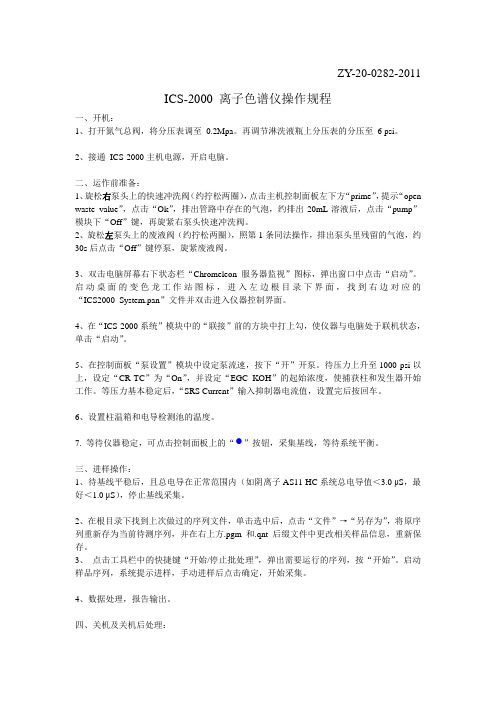
ZY-20-0282-2011ICS-2000 离子色谱仪操作规程一、开机:1、打开氮气总阀,将分压表调至0.2Mpa。
再调节淋洗液瓶上分压表的分压至6 psi。
2、接通ICS-2000主机电源,开启电脑。
二、运作前准备:1、旋松右泵头上的快速冲洗阀(约拧松两圈),点击主机控制面板左下方“prime”,提示“open waste value”,点击“Ok”,排出管路中存在的气泡,约排出20mL溶液后,点击“pump”模块下“Off”键,再旋紧右泵头快速冲洗阀。
2、旋松左泵头上的废液阀(约拧松两圈),照第1条同法操作,排出泵头里残留的气泡,约30s后点击“Off”键停泵,旋紧废液阀。
3、双击电脑屏幕右下状态栏“Chromeleon服务器监视”图标,弹出窗口中点击“启动”。
启动桌面的变色龙工作站图标,进入左边根目录下界面,找到右边对应的“ICS2000_System.pan”文件并双击进入仪器控制界面。
4、在“ICS-2000系统”模块中的“联接”前的方块中打上勾,使仪器与电脑处于联机状态,单击“启动”。
5、在控制面板“泵设置”模块中设定泵流速,按下“开”开泵。
待压力上升至1000 psi以上,设定“CR-TC”为“On”,并设定“EGC KOH”的起始浓度,使捕获柱和发生器开始工作。
等压力基本稳定后,“SRS Current”输入抑制器电流值,设置完后按回车。
6、设置柱温箱和电导检测池的温度。
7. 等待仪器稳定,可点击控制面板上的“ ”按钮,采集基线,等待系统平衡。
三、进样操作:1、待基线平稳后,且总电导在正常范围内(如阴离子AS11-HC系统总电导值<3.0 μS,最好<1.0 μS),停止基线采集。
2、在根目录下找到上次做过的序列文件,单击选中后,点击“文件”→“另存为”,将原序列重新存为当前待测序列,并在右上方.pgm和.qnt后缀文件中更改相关样品信息,重新保存。
3、点击工具栏中的快捷键“开始/停止批处理”,弹出需要运行的序列,按“开始”。
TICS2000使用说明书(V1.36)该触控式控制器采用我公司自主研发的控制系统软件,显示窗口组态程序、控制操作系统程序,具有自主知识产权。
采用10.2″TFT显示屏、亮度高达200cd/㎡分辩率1024×600 (W×H dots)显示屏为TFT LCD,65535万色真彩显示。
1.1 设定控钮◆采用触控屏输入方式1.1.1设定值输入键盘◆如果输入错误数据,会出现这种情况。
当数据输入完毕后,按“确定”键后,如果设定的数值超出“温度高限、温度低限”时。
TICS2000均会自动更改为高限或低限数值。
使用说明书上电开机初始化画面如下:按“目录”键进入 按“密码管理”键进入按“操作设定”键进入1.1 初始画面◆上电后显示的第一个画面,如下图所示。
在显示该画面15S后,系统将自动切入到监视画面。
图1-2 初始画面图1-11 初始画面1.2 监视画面------停止画面◆从初始画面切换过来的画面,用户可以通过监视画面切换到其它画面,监视画面如下图所示:①②③④⑤⑥⑦⑧图1-12停止画面①设定温度值输入窗口;②实际温度值显示窗口;③主菜单进入按键;(如果选择为“按键锁定”需要输入二级密码方可进入)④功能开关按键区;⑤高温老化房控制状态显示区⑥加热量输出量百分比显示状态条;⑦老化房定时结束提示窗口⑧高温老化房停止/启动开关1.3 监视画面------运行画面①②③图1-13运行画面①升温、恒温、降温状态显示;②当前运行时PID 参数值;③已运行时间或定时剩余时间显示区;1.4 设备的运行与停止高温老化房的运行与停止都通过单击“⑧”按键来控制,设备的运行与停止都会弹出“确认”与'“取消”按键。
如下图所示;设备停止时按“⑧”按键状态设备运行时按“⑧”按键状态单击“确定”后运行或停止设备,单击“取消”退出返回;1.5 电气状态及温度、运行时间状态显示区:电气状态:当各状态亮绿灯时,表示当前的状态已启动;RUN:当按下“⑧”按钮时,该灯亮,STOP灯熄灭;(V1.0版后增加启动确认按键)STOP:当按下“⑧”按钮时,该灯亮,运行灯熄灭;(V1.0版后增加停止确认按键)循环风机运行:当按下“⑧”按钮时,该灯亮;加热输出量:根据温度设定值设定的大小,自动控制其输出;(V1.0版后增加功率百分比显示条)手动排风:当电控箱面板的排风开关按下时,触摸屏的功能开关区的手动排风开关显示出现,当按下“排风开关”按钮时该灯亮,再次按下该开关,排风即关闭;自动排风:由控制器自动控制排风,输出时为:PV-SV => 自动开启值时开启;延时排风:当设定延时排风时间时,如按下“⑧”按钮老化房处于停止状态或启动定时定时到达,老化房排风扇自动运行,时间到达后,自动关闭输出。
ZLSN2000嵌入式设备联网模块用户手册嵌入式设备联网解决方案版权©2008上海卓岚信息科技有限公司保留所有权力ZL DUI20081127.1.0版权©2008上海卓岚信息科技有限公司保留所有权力版本信息对该文档有如下的修改:修改记录日期版本文档编号修改内容2008-11-27Rev.1ZL DUI20081127.1.0发布版本2009-8-16Rev.2ZL DUI20081127.1.0更新版本2012-7-13Rev.3ZL DUI20081127.1.0更新版本2018-5-13Rev.4ZL DUI20081127.1.0更新版本所有权信息未经版权所有者同意,不得将本文档的全部或者部分以纸面或者电子文档的形式重新发布。
本文档只用于辅助读者使用产品,上海卓岚公司不对使用该文档中的信息而引起的损失或者错误负责。
本文档描述的产品和文本正在不断地开发和完善中。
上海卓岚信息科技有限公司有权利在未通知用户的情况下修改本文档。
目录1.概述 (5)2.功能特点 (6)3.技术参数 (8)4.接口定义 (9)5.硬件电路 (11)6.使用方法 (13)6.1.使用概述 (13)6.2.软件安装 (14)6.3.参数配置 (14)6.4.TCP通讯测试 (20)6.5.虚拟串口测试 (22)6.6.Modbus TCP测试 (25)7.工作模式和转化协议 (26)7.1.虚拟串口模式 (28)7.2.直接TCP/IP通讯模式 (28)7.3.设备对联方式 (30)8.设备调试 (32)8.1.网络物理连接 (32)8.2.网络TCP连接 (32)8.3.数据发送和接收 (33)8.4.ZLVircom远程监视数据 (33)9.M ODBUS高级功能 (34)9.1.启用Modbus网关 (35)9.2.多主机功能 (35)9.3.多主机参数 (36)9.4.存储型和非存储型 (37)10.网口修改参数 (37)11.设备管理函数库 (38)12.串口修改参数 (38)13.远程设备管理 (39)14.订货信息 (40)15.售后服务和技术支持 (40)上海卓岚信息科技有限公司Tel:(021)643251891.概述ZLSN2000是串口转以太网嵌入式模块,它为嵌入式系统、单片机接入基于TCP/IP的网络提供了快捷、稳定、经济的方法。
ICS-2000皮带秤的使用与维护一、使用:1、运行:□若运行画面数据全部为零,说明系统失去通讯;·运行画面的第一行为计算机的硬时钟;□该硬时钟需运行可靠,并不得随意更改,否则会造成“查询/打印”、“传输数据”的时间出错;·第一列为各下位机的机号;·第二列为各皮带机的瞬时输送量;·第三列为各皮带机的运行速度,若速度为零,说明该皮带机已停止运行;·第四列为各皮带秤的总累计量,该累计量可在“设定”中清零;·第五列为各皮带秤的动态零点,该数据在动态校零后自动产生,每进行一次动态校零该数据就会发生一次变化。
2、查询打印:·通过查询菜单中“传输数据”可将各皮带秤中(昨天和昨天以前)每天各班的累计量以月报的格式存入计算机,随时提供查询或打印;※按照计算机提示操作“查询/打印”,按“Esc”键返回;※在“运行”状态下,按“P”键,可打印当时运行画面的所有数据。
二、维护:·每天在运行前需做一次动态校零,并将动态零点做好记录备查;□新安装的系统或经过重新建秤的系统,在连续正常运行一周内应将每天的动态零点进行分析,并确定动态零点的正常变化范围;□根据本次零点与上次零点的差值,可判断系统状态是否良好,若差值超过正常范围,需立即通知维修人员;(皮带机和秤架经调整过后,造成的零点变化属正常现象)。
·每隔一个月需用挂砝码的方法做一次“实物标定”(用建秤时保存的砝码和累计量)※将原保存的累计量作为本次的“实际重量”;·主机接口不得随便移动,最好放在不易被接触的地方;·秤架及秤架的周围要保持清洁,秤架及其前后各三组托辊架上所有紧固件要保持紧固;三、故障查找:1、运行画面的数据全部为零:·重新启动主机接口电源;·检查通讯插头是否松动。
2、皮带机在运行,但速度显示为零:·检查皮带机的常开触点接触是否良好。
Chromeleon色谱工作站
操作指南
戴安中国有限公司技术服务中心
2005.2
注意:以下操作步骤以阴离子分析,手动进样为例。
“”为单击鼠标左键;
“”为双击鼠标左键;
“”为单击鼠标右键。
* 建立控制面板
1. 从“开始”处依次选择Programs, Chromeleon和Chromeleon;
2. 点击计算机代码,双击与实际情况一致的控制面板;
3. 确认各模块的“Connected”图标均为绿色后,设置淋洗液的液位
开泵,设定流速;
注意:如果操作条件固定(不进行排气泡、更换系统等操作),开/关机分别点击Startup和Shutdown即可。
5. 点击兰色圆形图标(Acquisition On/Off);
6. 进入Pump_ECD – ECD_1;
7. 设置电导池和柱温箱的温度,选择抑制器类型, 输入淋洗液浓度,
点击“确定”开始采集基线。
* 设定运行程序
1. 依次点击File和New,选择Program File;
2. 点击“下一步”;
3. 设置高/低压极限和流速,点击“下一步”;
4. 设置手动进样,进样时间为60秒;
5. 将Acquisition t ime调整至0~15分钟,点击“下一步”;
6. 设置电导池和柱温箱的温度,选择抑制器类型, 输入淋洗液浓度,
点击“下一步”;
7. 点击“下一步”;
8. 选择“Review the program in a new window”,点击“完成”;
注意:绿色字体为注释信息,不起作用。
10. 存盘退出(推荐存入独立的“program”子目录中)。
* 建立方法文件
1.依次点击File和New,选择Method File;
2. 依次点击File和Save as,存盘退出(推荐存入独立的“method”
子目录中)。
* 建立样品表
1.依次点击File和New,选择Sequence(using Wizard);
2.点击“下一步”(连续四次);
3. 选择正确的程序文件,点击“Open”;
4.选择正确的方法文件,点击“Open”;
5. 选择正确的报告文件,点击“Open”;
6. 存盘退出;
5.修改标准点的名称、类型和数量。
注意:如果使用AS50自动进样器,应根据实际情况在“Pos”下设定样品瓶的位置。
* 运行标准样品
1. 点击兰色圆形图标(Acquisition On/Off),选择“Yes”,停止采
集基线;
2. 依次点击Batch和Start;
3. 点击“Add”,打开需要运行的样品表;
4. 点击“Start”;
注意:使用自动进样器时,开始进样。
5.注入标准样品,点击“确定”。
* 处理标准曲线(以多点校正为例)
1. 依次点击File和Browser;
2. 双击需要处理的标准样品文件(第一个标准点);
3. 依次点击View和QNT-Editer;
4. 点击屏幕左下角“General”,在“Dimension of”处输入浓度单
位“mg/L”;
5. 点击相邻的“Detection”,设定最小峰面积;
6. 点击键盘的“↓”,选择“是(Y)”;
7. 将新生成的“Minimum Area”重新选为“Inhibit Integration”,
按“Enter”键;
8. 点击键盘的“↓”后,将鼠标放在水负峰和F-之间的水平基线处,
在Ret. Time[min]的第三行输入屏幕左下角显示的时间“2.00”;
9. 点击相邻的“Peak Table”,选择
Peaktable;
10. 依次点击OK和确定;
11. 在“Peak Name”下顺序输入离子名称; 注意:定性分析到此结束。
如需进行单点校正,直接执行第15步。
12. 在“Cal. Type”下“Lin”处双击左键;
13. 选择“Linear with Offset”,点击“OK”;
14. 在“LOff”处点击右键,从弹出的对话框中选择“Fill Column”;
15. 点击相邻的“Amount Table”;
注意:如果进行单点校正,在“Amou
nt [mg/L]”处输入各个组分的
浓度,存盘退出。
16. 双击“Amount [mg/L]”;
17. 在“Assign Standards on the”后面选择“Name”,再点击
“Auto-Generate”;
18. 按“Apply”键;
19. 按“OK”键退出;
20. 在“Amount”下输入各个组分的标准点浓度,屏幕右上方立即出
现某一离子的标准曲线;
21. 点击“Integration”图标,选择“Calibration”,检查标准曲
线合格后,存盘退出。