模型构建器 - 创建工具creating-tools-in-modelbuilder-tutorial
- 格式:pdf
- 大小:883.91 KB
- 文档页数:15
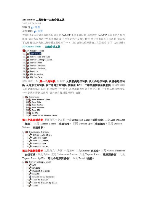
ArcToolbox工具详解—三维分析工具2010-06-04 16:04转载自gis理想最终编辑gis理想大家好!最近看到很多群友问到有关ArcMAP里的工具问题这里我把ArcMAP工具里的各项列出来请大家先熟悉一些基本的常识有些单词也不是很好翻译估计会有很多不当之处请大家不吝赐教!这次先把三维分析工具整理了一下以后会陆续整理其他工具的说明好了言归正传!3D Analyst Tools 三维分析工具这里请看上图第一个是转换里面有从要素类进行转换从文件进行转换从栅格进行转换从地形开始转换从三角网开始转换转换至KML三维图层转换至要素类而这些里面又有更加细化的工具这里就举一个例子从地形转换里另有两个方面一个是从地形到栅格一个是从地形到三角网请大家自行对照理解!如图:第二个是表面功能里面有五个小方面一是Interpolate Shape(插值形状)二是Line Of Sight (视线)三是Surface Length(表面长度)四是Surface Spot(表面地点)五是SurfaceV olume(表面体积)第三个是栅格修补这里有八个方面一是IDW 二是Kriging(克里金)三是Natural Neighbor (自然邻域)四是Spline 五是Spline with Barriers 六是Topo to Raster(地形到栅格)七是Topo to Raster by File(用文件地形到栅格)八是Trend(趋势)第四个是栅格计算这个很好理解一是除二是浮点三是取整四是减五是加六是乘第五是栅格重分类一是查找二是用ASCII文件重分类三是用表重分类四是重分类五是切片第六是栅格表面一是坡向二是等高线三是等高线列表四是带路障的等高线五是曲率六是填挖七是山影八是观察点九是坡度十是视域第七是地形一是增加要素类到地形二是增加地形点三是增加地形金字塔四是建立地形五是改变地形参考比例六是创建地形七是从地形中移去要素类八是移去地形点九是移去地形金字塔第八是TIN的创建一是创建TIN二是划定TIN数据区域三是编辑TIN第九是TIN的表面一是消除节点二是从中挑出三是多边形插值成多个面四是TIN坡向五是TIN轮廓六是TIN差异七是TIN表面体积八是TIN坡度第三章 Model Builder第一节 Model基础前面讲了很多的地里处理的概念,涉及好几个地里处理运行方式。

自动激活建模工具包(Auto-Activate Modeling Toolkit)“自动激活建模工具包”(Auto-Activate Modeling Toolkit)选项将强制Maya 使用“建模工具包”(Modeling Toolkit)的选择和变换工具。
启用此选项时,将始终使用“建模工具包”(Modeling Toolkit)的工具,而不考虑“建模工具包”(Modeling Toolkit)是否处于活动状态。
禁用此选项时,仅当从“建模工具包”(Modeling Toolkit)窗口中选择“建模工具包”(Modeling Toolkit)的工具时,才使用这些工具。
按活动组件模式按钮时(On pressing active component mode button)以下选项决定当选择已处于活动状态的组件模式按钮时会发生的情况:切换组件模式(Toggle out of Component Mode)如果启用此选项,Maya 会切换到对象模式,并取消激活“建模工具包”(Modeling Toolkit)。
使用自定义命令(Use Custom Command)如果启用此选项,在此字段中输入的任何自定义MEL 命令都将添加到热盒中并执行。
选择未使用空间范围(Select Dead Space Range)设置Maya 在其中查找组件的“未使用空间范围”(Dead Space Range)。
未使用空间是指场景中对象周围的空白区域。
如果此范围大于0 且光标位于未使用空间之内,Maya 会亮显此范围内的最近组件。
默认情况下,“选择未使用空间范围”(Select Dead Space Range)设置为 4 像素。
调整未使用空间范围(Tweak Dead Space Range)设置Maya 要在其中查找组件的“调整未使用空间范围”(Tweak Dead Space Range)。
如果此范围大于0 且您处于调整模式,Maya 会亮显此范围内的最近组件。

ArcGIS ModelBuilder 是一个可视化工具,用于创建、管理和执行地理信息系统(GIS) 工作流程。
以下是一个简单的ArcGIS ModelBuilder 示例:1. 打开ArcGIS,然后点击"工具箱"(Toolbox)。
2. 在"工具箱" 中,找到"模型构建器"(ModelBuilder)并打开它。
3. 在"模型构建器" 窗口中,右键单击"模型"(Model)选项卡,然后选择"添加模型"(Add Model)。
4. 为新模型命名,例如"简单分析"(Simple Analysis),然后单击"确定"(OK)。
5. 在"模型构建器" 窗口中,从"工具箱"(Toolbox)中拖放所需的工具到"模型"(Model)选项卡上。
例如,你可以拖放"裁剪"(Clip)工具、"重分类"(Reclassify)工具和"栅格转矢量"(Raster to Vector)工具。
6. 使用"连接线"(Connector)工具将各个工具连接起来,以定义工作流程。
例如,将"裁剪"(Clip)工具的输出连接到"重分类"(Reclassify)工具的输入,然后将"重分类"(Reclassify)工具的输出连接到"栅格转矢量"(Raster to Vector)工具的输入。
7. 双击每个工具以设置参数。
例如,对于"裁剪"(Clip)工具,你需要指定输入数据、裁剪区域和输出数据;对于"重分类"(Reclassify)工具,你需要指定输入数据、分类方法和输出数据等。

机器学习模型创建流程Creating a machine learning model involves several important steps. First and foremost, it is essential to define the problem you are trying to solve. This step requires a clear understanding of the objectives, the available data, and the expected outcomes. Essentially, you need to ask yourself what you are trying to achieve with the model and how it will benefit your business or project.在创建机器学习模型时,首要步骤是定义您要解决的问题。
这一步需要清晰地理解目标、可用数据和预期结果。
基本上,您需要问自己:您尝试通过模型实现什么,它将如何使您的业务或项目获益。
Once the problem is well-defined, the next step is to gather and prepare the data. Data is the heart of any machine learning model, and having high-quality data is crucial for the success of the model. This step involves collecting relevant data from various sources, ensuring its accuracy, and organizing it in a usable format for the model. Data preprocessing techniques such as cleaning, transformation, and normalization may be necessary to prepare the data for training.一旦问题定义清楚,下一步就是收集和准备数据。
Arcgis中的模型构建器(ModelBuilder)基础模型构建器(ModelBuilder)是一个用来创建、编辑和管理模型的应用程序。
模型是将一系列地理处理工具串联在一起的工作流,它将其中一个工具的输出作为另一个工具的输入。
也可以将模型构建器看成是用于构建工作流的可视化编程语言。
另一种解释:模型构建器(ModelBuilder)是创建模型和模型工具的一种方式。
模型不过是链接到一起的一系列工具串和数据;其中,一个工具的输出会反馈为另一个工具的输入。
当您保存模型时,该模型将变成一个模型工具。
一、模型构建器(ModelBuilder)基础1、模型构建器(ModelBuilder)界面模型构建器的界面结构简单,其中包含下拉菜单、工具条工具及快捷菜单选项(如下图所示)。
通过右键单击可以使用整个模型或任何单个模型元素(变量、连接器或工具)的快捷菜单。
在模型中用于拖动工具并将其连接到变量的空白区域称为画布,显示相互连接的工具和变量的外观及布局称为模型图。
主菜单上有六个下拉菜单,如下表所示:2、模型的三个属性集ModelBuilder 具有更改模型的如下三个属性集:模型属性——更改模型名称、标注、描述、相对路径、参数属性、模型环境、帮助和迭代。
逻辑示意图属性——更改图中元素的排列和图的整体颜色和样式。
显示属性——更改各个元素的外观和其他图形属性。
3、模型构建器基础知识1)模型画布模型画布是模型中的白色空白区域。
2)模型图模型图是模型中彼此相连的工具和变量的外观和布局。
3)模型元素模型元素主要分三个类型——工具、变量和连接符。
(1)工具地理处理工具是模型工作流的基本组成部分。
工具用于对地理数据或表格数据执行多种操作。
工具被添加到模型中后,即成为模型元素。
(2)变量变量是模型中用于保存值或对磁盘数据进行引用的元素。
有以下两种类型的变量:①数据:数据变量是包含磁盘数据的描述性信息的模型元素。
数据变量中所描述的数据属性包括字段信息、空间参考和路径。
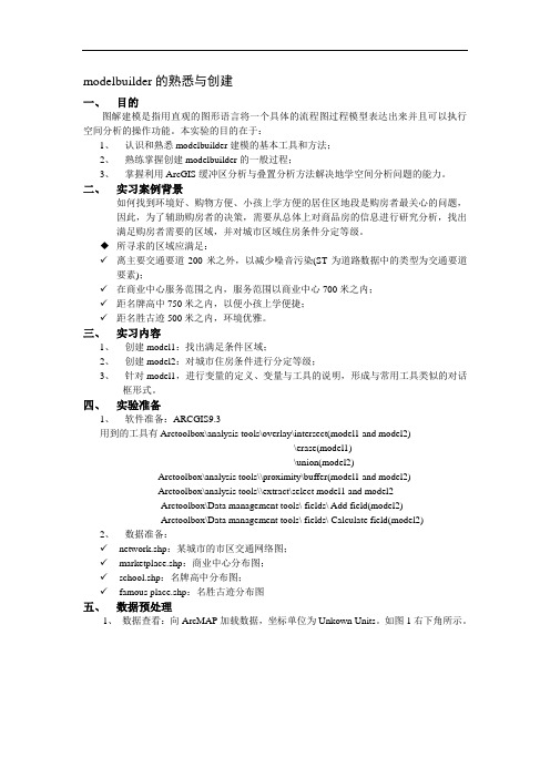
modelbuilder的熟悉与创建一、目的图解建模是指用直观的图形语言将一个具体的流程图过程模型表达出来并且可以执行空间分析的操作功能。
本实验的目的在于:1、认识和熟悉modelbuilder建模的基本工具和方法;2、熟练掌握创建modelbuilder的一般过程;3、掌握利用ArcGIS缓冲区分析与叠置分析方法解决地学空间分析问题的能力。
二、实习案例背景如何找到环境好、购物方便、小孩上学方便的居住区地段是购房者最关心的问题,因此,为了辅助购房者的决策,需要从总体上对商品房的信息进行研究分析,找出满足购房者需要的区域,并对城市区域住房条件分定等级。
◆所寻求的区域应满足:✓离主要交通要道200米之外,以减少噪音污染(ST为道路数据中的类型为交通要道要素);✓在商业中心服务范围之内,服务范围以商业中心700米之内;✓距名牌高中750米之内,以便小孩上学便捷;✓距名胜古迹500米之内,环境优雅。
三、实习内容1、创建model1:找出满足条件区域;2、创建model2:对城市住房条件进行分定等级;3、针对model1,进行变量的定义、变量与工具的说明,形成与常用工具类似的对话框形式。
四、实验准备1、软件准备:ARCGIS9.3用到的工具有Arctoolbox\analysis tools\overlay\intersect(model1 and model2)\erase(model1)\union(model2)Arctoolbox\analysis tools\\proximity\buffer(model1 and model2)Arctoolbox\analysis tools\\extract\select model1 and model2Arctoolbox\Data management tools\ fields\ Add field(model2)Arctoolbox\Data management tools\ fields\ Calculate field(model2)2、数据准备:✓network.shp:某城市的市区交通网络图;✓marketplace.shp:商业中心分布图;✓school.shp:名牌高中分布图;✓famous place.shp:名胜古迹分布图五、数据预处理1、数据查看:向ArcMAP加载数据,坐标单位为Unkown Units。
自动激活建模工具包(Auto-Activate Modeling Toolkit)“自动激活建模工具包”(Auto-Activate Modeling Toolkit)选项将强制Maya 使用“建模工具包”(Modeling Toolkit)的选择和变换工具。
启用此选项时,将始终使用“建模工具包”(Modeling Toolkit)的工具,而不考虑“建模工具包”(Modeling Toolkit)是否处于活动状态。
禁用此选项时,仅当从“建模工具包”(Modeling Toolkit)窗口中选择“建模工具包”(Modeling Toolkit)的工具时,才使用这些工具。
按活动组件模式按钮时(On pressing active component mode button)以下选项决定当选择已处于活动状态的组件模式按钮时会发生的情况:切换组件模式(Toggle out of Component Mode)如果启用此选项,Maya 会切换到对象模式,并取消激活“建模工具包”(Modeling Toolkit)。
使用自定义命令(Use Custom Command)如果启用此选项,在此字段中输入的任何自定义MEL 命令都将添加到热盒中并执行。
选择未使用空间范围(Select Dead Space Range)设置Maya 在其中查找组件的“未使用空间范围”(Dead Space Range)。
未使用空间是指场景中对象周围的空白区域。
如果此范围大于0 且光标位于未使用空间之内,Maya 会亮显此范围内的最近组件。
默认情况下,“选择未使用空间范围”(Select Dead Space Range)设置为4 像素。
调整未使用空间范围(Tweak Dead Space Range)设置Maya 要在其中查找组件的“调整未使用空间范围”(Tweak Dead Space Range)。
如果此范围大于0 且您处于调整模式,Maya 会亮显此范围内的最近组件。
如何使用create_model方法创建高质量的机器学习模型在机器学习中,使用create_model方法是创建高质量模型的重要步骤之一。
create_model方法是一种功能强大的工具,可以帮助数据科学家和机器学习工程师快速建立和调优模型,以解决各种复杂的问题。
本文将深入探讨create_model方法的作用和用法,以及如何利用它来创建高质量的机器学习模型。
1. 什么是create_model方法create_model方法是一种在机器学习库中常见的功能,例如在Python中的scikit-learn库和在R语言中的caret包中都有这个方法。
它的作用是根据给定的数据集和模型参数,创建一个新的机器学习模型。
这个方法可以根据数据的特点和需求,选择合适的算法、超参数和特征工程方法,从而构建出最优的模型。
2. create_model方法的用法在使用create_model方法时,首先需要准备好待处理的数据集。
这包括数据的清洗、特征工程和标签处理等步骤。
可以使用create_model方法来创建一个初始模型。
在创建模型时,可以选择不同的算法(如逻辑回归、随机森林、支持向量机等)、超参数设置和特征选择方法。
通过反复尝试和调优,可以找到最适合数据集的模型。
3. create_model方法的作用create_model方法的主要作用是帮助用户快速建立和调优模型,以解决实际问题。
通过尝试不同的算法和参数设置,可以找到最适合数据的模型。
create_model方法还可以帮助用户理解不同算法之间的差异,以及不同参数对模型性能的影响。
通过这种方式,用户可以更好地选择和理解模型,从而提高机器学习的效率和准确性。
4. 个人观点和理解在我看来,create_model方法是机器学习中一项非常重要的工具。
它可以帮助我们在短时间内构建出高质量的模型,减少了繁琐的实验和尝试过程。
create_model方法还可以帮助我们更好地理解数据和模型,从而更好地解决实际问题。
ModelBuilder - Creating Tools TutorialTable of ContentsTutorial: Creating tools with ModelBuilder . . . . . . . . . . . . . . . . . . . . . . . . . 3Tutorial: Creating tools with ModelBuilderThis tutorial takes you step-by-step through the process of creating a model tool. In this tutorial, the model built in the Executing tools in ModelBuilder tutorial is made into a useful tool by exposing model variables as model parameters.For a broad overview of creating model tools, see A quick tour of creatingtools with ModelBuilder .It is assumed that you have installed ArcGIS Desktop (ArcView, ArcEditor, or ArcInfo) before you begin this tutorial. The data required for this tutorial (included on the ArcGIS Desktop CD) by default is installed in C:\arcgis\ArcTutor . The tutorial scenario is fictitious, and the original data has been adapted for the tutorial.To avoid corrupting the original data, copy the ModelBuilder folder from C:\arcgis\ArcTutor to the C drive on your computer. If you are copying the data to another drive or location, make sure to use that drive for all the steps below.Steps:1.Open the map document.2.Create the model.3.Expose tool parameters.4.Create model parameters.5.Rename model elements.6.Set model parameter order.7.Set model parameter type.8.Set filters on model parameters.9.Set symbology for output data.10.Manage intermediate data.11.Change general model properties.12.Document the model.1-Open the map documentBrowse to the C:\ModelBuilder folder in Windows Explorer and double click the Extract Vegetation.mxd.This will start ArcMap and open the map document, orSteps:1.Start ArcMap by clicking Start >All Programs >ArcGIS >ArcMap 10.2.On the ArcMap - Getting Started dialog box, click Existing Maps >Browse for more.The Open ArcMap Document dialog box appears.3.Browse to C:\ModelBuilder folder, select Extract Vegetation.mxd, and click Open .Complexity:BeginnerData Requirement:ArcGIS Tutorial Data SetupGoal:Learn how to create a model tool.This opens the Extract Vegetation.mxd.2-Creating the initial modelFollow the steps in Executing tools in ModelBuilder. The same model is used in this tutorial as the starting point.If the model was saved previously, open the model by right-clicking the model and selecting Edit. If this model was saved after the model was run in the "Executing tools in ModelBuilder tutorial," the model elements may have a drop shadow around them. To remove the drop shadows, validate the entire model by clicking the Validate Entire Model button on the ModelBuilder toolbar.Double-click the example model from the Catalog window. The tool dialog box opens but shows no parameters, as illustrated below.If you run the tool by clicking OK, the model will run. The output of the model (ClippedFC) will not be added to the ArcMap table of contents, even though Add To Display was checked for the output variable. The reason is that when a model is run from its tool dialog box, the Add To Display setting is ignored. To add the output to the display, you must make the output variable a model parameter.Another reason for creating model parameters is that you want to run the model with different inputs without having to open ModelBuilder every time, as illustrated below.Once the model parameters have been created, you can execute the model from its tool dialog box, supplying different values for the Input Roads,Buffer Distance,Input Vegetation,Output Clipped Feature Class, and XY Tolerance parameters. You don't have to open ModelBuilder each time you want to run the model—you can use the tool dialog box instead. An added advantage of running a model from its tool dialog box is that a result in the Results window is created; running a model within ModelBuilder does not create a result in the Results window.The remaining steps will expose model variables as parameters so they appear on the model tool dialog box as shown above.3-Exposing tool parametersTo define the Buffer Distance and XY Tolerance parameters, you need to create model variables for them.When you add a tool to a model, model variables are automatically created for input and output datasets, but not for any other tool parameters. The reason is aesthetics—if variables were automatically created for every tool parameter, the model diagram would quickly become unreadable. For example, when you add the Buffer tool to a model, a variable is automatically made for the Output Feature Class parameter. After you right-click Buffer and fill in the Input Features parameter, a model variable is created for the input features. All other parameters, such as Distance,Side Type, and End Type, are not automatically added as variables in the model. The steps below create model variables for Distance [value or field] and XY Tolerance.Steps:1.In the Catalog window, right-click the model and click Edit. This opens the model inModelBuilder.2.Right-click Buffer.3.Click Make Variable>From Parameter>Distance [value or field].This adds the Distance parameter as a variable in the model.4.Right-click Clip.5.Click Make Variable>From Parameter>XY Tolerance.4-Creating model parametersNow that you've created variables for Distance and XY Tolerance, you're ready to make model parameters.Steps:1.Right-click Distance [value or field]and check the Make Parameter option, as illustratedbelow.The letter P appears beside the variable, indicating it is a model parameter. This modelparameter then also appears on the model tool dialog box.2.Create model parameters for the following variables (do not make a model parameter forBufferedFC):•PlanA_Roads•vegetype•XY Tolerance•ClippedFC5-Renaming model elementsModelBuilder assigns default names to variables. Variable names are used for parameter names on the model tool dialog box. It is good practice to rename variables, especially if they are model parameters.Steps:1.Right-click PlanA_Roads and click Rename.2.Type Input Roads and click OK.The name of the variable changes to Input Roads.3.Rename the remaining variables as follows:•Rename Distance [value or field]to Buffer Distance.•Rename vegetype to Input Vegetation.•Rename ClippedFC to Output Clipped Feature Class.4.Save the model. You do not need to exit ModelBuilder.5.Double-click the model from the Catalog window to open the model tool dialog box. You mayhave to move or minimize the ModelBuilder window to access the Catalog window. The modeltool dialog box should look similar to the illustration below. The order of the parameters maybe different on your dialog box, but this is not an issue since you'll change the order below.You can execute your tool by clicking OK, but it is suggested that you choose a differentoutput feature class before executing. The tool executes, and the output feature class is addedto the ArcMap table of contents. Unlike running a model within ModelBuilder, running themodel from its dialog box does not change the model diagram.6-Setting model parameter orderAs illustrated above, the order of the parameters is not ideal. The standard practice is to order parameters as follows:•Required input datasets•Other required parameters that affect tool execution•Required output datasets•Optional parametersSteps:1.In ModelBuilder, click Model>Model Properties.2.Click the Parameters tab.3.Choose the Input Roads parameter and move it to the top using the Up and Down arrowbuttons on the right side.4.Change the position of other parameters as shown below:7-Setting model parameter typeOnce the model parameters are set in the correct order, change the type of the parameter. If a parameter is a required parameter of a tool in the model, you will not be able to change the type to optional from these settings.Steps:1.In ModelBuilder, click Model>Model Properties.2.Click the Parameters tab.3.Click the cell under the Type category for XY Tolerance. A list appears with two options. Forthis example, keep XY Tolerance as an optional parameter and the rest as a requiredparameter type as shown in the illustration below.8-Setting filters on model parametersYou can restrict the type of input to any parameter by applying filters to parameters. The model in this example expects the Input Roads parameter to be line features. In the following steps, the parameter is modified by applying a filter so that it only accepts line features.Steps:1.Click Model>Model Properties.2.Click the Parameters tab.3.Choose Input Roads and click the cell under the Filter category.4.Choose the Feature Class filter.The Feature Class dialog box opens.5.Uncheck all the types except Polyline and click OK.6.Click OK on the Model Properties dialog box to apply the filter.9-Setting symbology for output dataThe output of a model can be set to have a particular symbology that is used to display the output. For this example, the symbology is based on the type of vegetation within the buffer zone. To set the symbology for the output data, the first step is to create a layer file, and the second step is to define the layer file in the output data properties. For this tutorial, a layer symbology file has been created for you.Steps:1.In the ModelBuilder window, right-click Output Clipped Feature Class and click Properties.2.Click the Layer Symbology tab.3.Browse the layer file from the ToolData folder that you copied inC:\ModelBuilder\ToolData.4.Choose OutputSymbology.lyr and click Add.5.Click OK.Learn more about creating a layer symbology file10-Managing intermediate dataWhen you run a model, output data is created for each process in the model. Some of the data created is of no use after the model is run since it was only created to connect to another process that creates new output. Such data is called intermediate data. All outputs except the final output, or those that have been made model parameters, are automatically made intermediate data in the model. In this example, the output of the Buffer tool is only useful as an input to the Clip tool and is not used after that, so the Intermediate option is checked. You can choose to save the intermediate data by unchecking the Intermediate option.11-Changing general model propertiesYou can set the model name, label, and description for the model.Steps:1.Click Model>Model Properties from the ModelBuilder interface.2.Type ExtractVegetationforProposedRoads for the name of the model. No spaces areallowed in the model name.3.Type Extract Vegetation for Proposed Roads in the Label text box. Spaces areallowed in the model label. This label is used to display the model name in the Catalogwindow.4.Type the desired text in the Description text box.Check the Store relative path names (instead of absolute paths)option so that you canshare your model tool or move your model data and model to a different location. This option isnot used in this tutorial but has been introduced here as a good practice to follow for yourfuture models and model tools that you will share.Learn more about the relative path option5.Click OK.6.Save the finished model and exit ModelBuilder.Double-click the model from the Catalog window to open the model tool dialog box. Since the model was saved with the predefined values, all the parameters on the dialog box are filled in.You can change the value of any parameter here by entering a new value. Click OK to run. The final output of the model (Output Clipped Feature Class) is added to the display by default, and the model messages are posted in the Results window. To see your results, uncheck theVegetation Type layer in the map document table of contents.12-Documenting the modelIt is always a good practice to document the model before you share it. To document: Steps:1.Right click the model in Catalog window and click Item Description.This opens the Item Description window, displaying the Description page.2.Click the Edit button on the Item Description windowThis opens the documentation editor to enter the item description.3.Type in appropriate description for each item in this model and click the Save button.To learn more about documenting take A quick tour of documenting tools and toolboxes Additional analysisIf you want to do some analysis with the model, you can add the Summary Statistics tool to get a summary table of affected area by vegetation type within the buffer polygons around the proposed roads.The steps below will also show you how to use a model as a tool inside another model.Steps:1.Open a new model by clicking the ModelBuilder button on the ArcMap Standard toolbar.2.Now that you have created a model tool, you can use it just like any other tool. You can addthe model tool to a new model by dragging it from the Catalog window into the new model, asillustrated below.Since the model tool had predefined values for input and output parameters, it is added to the new model with input and output variables (the blue and green ovals). Note that not allparameters of the model tool are exposed when added in another model. Also, the original names of the input datasets have been used. You can make variables and rename them as described earlier in this tutorial.3.Open the Search window (if not already open in ArcMap) by clicking Geoprocessing>Search For Tools.This opens the Search window.4.In the Search window, type Summary Statistics and click the Search button.5.Drag the tool into the model.6.Double-click the Summary Statistics element to open the tool dialog box.7.For the Input Table parameter, click the arrow and choose Output Clipped Feature Classwith a blue recycle icon next to it. This recycle icon means it is a variable in the model.8.For the Output Table parameter, browse to the output geodatabase(C:\ModelBuilder\Scratch\Output.gdb), type AffectedVegetation for the name, then click Save.9.For the Statistic Field(s)parameter, choose Shape_Area from the list.10.Click the cell next to Shape_Area under Statistic Type and choose SUM from the drop downlist.11.For the Case field parameter, choose VEG_TYPE from the list.The completed model with the Summary Statistics dialog box is illustrated below.12.Click OK.13.Right-click Output Clipped Feature Class (the green oval)and check Add to Display. Thisadds the output to the display after the model runs.14.Right click and check the Add to Display option for the AffectedVegetation variable. This willadd the ouput to the display after the model runs.15.Run the model.The output Output Clipped Feature Class and the AffectedVegetation table are added to the display in the ArcMap table of contents.16.Open the table by right-clicking and clicking Open.The table shows a summary of area by vegetation type within the buffer polygons that will beaffected by the proposed roads for plan A.。