基于PCIExpress总线的高速数据传输卡设计与实现
- 格式:pdf
- 大小:364.74 KB
- 文档页数:5
基于PCIe总线的车载高速网络设计与实现随着汽车行业的不息进步,车载网络的重要性日益凸显。
车载网络不仅能够提供丰富的娱乐和信息服务,还能实现车辆与车辆之间以及车辆与基础设施之间的高速通信。
基于PCIe (Peripheral Component Interconnect Express)总线的车载高速网络成为了一种广泛应用的技术解决方案。
本文将介绍基于PCIe总线的车载高速网络的设计原理与实现方法。
一、PCIe总线的概述PCIe总线是一种高性能、低延迟的串行总线技术,用于毗连计算机系统内部的各种外设和扩展卡。
它的带宽较高,能够支持多个设备同时传输数据。
在车载高速网络中,使用PCIe总线可以有效地提供高速数据传输和低延迟通信。
二、设计原理1. 硬件设计基于PCIe总线的车载高速网络的硬件设计需要思量传输速率、高速数据缓存、信号完整性和抗干扰等因素。
起首,选择合适的PCIe控制器芯片和外部设备芯片。
其次,设计高速数据缓存,用于存储大容量的数据,并通过PCIe总线进行传输。
此外,需要实行一系列的电磁屏蔽和抗干扰设计,以确保数据的传输质量和稳定性。
2. 软件设计基于PCIe总线的车载高速网络的软件设计主要包括驱动程序开发和通信协议设计。
开发适配于PCIe总线的驱动程序,能够实现与外设的稳定通信。
此外,为了实现车辆与车辆之间的高速通信,还需要设计相应的通信协议。
通信协议设计既要思量数据传输的速度和稳定性,也要保证数据的准确性和安全性。
三、实现方法1. 硬件实现基于PCIe总线的车载高速网络的硬件实现需要进行电路设计和PCB制作。
起首,按照硬件设计原理所需的要求,进行电路设计,并选取合适的元器件进行布局。
然后,通过PCB制作完成硬件装配。
2. 软件实现基于PCIe总线的车载高速网络的软件实现需要进行驱动程序开发和通信协议设计。
依据所选取的PCIe控制器芯片,开发相应的驱动程序,使其能够与外设通信。
同时,依据车辆与车辆之间的通信需求,设计相应的通信协议,并在驱动程序中实现。
Design and Implementation of a High-speed Data Transmission System based onPCI-Express ProtocolXing Yang Wu Qiong-zhi Department of complicated circuit system Department of complicated circuit system Beijing Institute of Technology Beijing Institute of Technology Beijing China Beijing China*********************************.cnYang Xin-ran Su Fu-shun Department of complicated circuit system Department of complicated circuit system Beijing Institute of Technology Beijing Institute of TechnologyBeijing China Beijing China****************************@Abstract - In order to meet the demand of high-speed digital data processing and achieve high-speed communication between digital front-ends and computer, we design and implement a transmission system based on FMC and PCI-Express protocol. This paper describes the basic hardware structure of the interface system, implements the high-speed data transmission via PCI-Express protocol on an FPGA and the highly modular design based-on FMC standard. The maximal speed of this transmission system is up to 34 Gbps. This system has a wide commonality as the communication interface module can be adjustable depending on different digital front-end.Keywords – PCI-Express, digital front-end, FMC, modularI.I NTRODUCTIONWith the growing amount of digital signal processing and its increasing speed development, how to achieve high-speed data transmission has become one of the emphases in the communication between digital front-end system and computer. PCI bus which was often used in the past cannot meet the requirements of high-speed data transmission system. So it is necessary to use a new data transmission technology. PCI-Express bus which is the newest generation of computer bus has represented the currently fastest solution to a point-to-point high-speed data transfer capability [1], the latest PCI-E 3.0 standard supports single-channel transmission rate of 8Gbps, up to 32 channels. Therefore, using the PCI-Express bus as the transmission interface between the digital front-end systems and computer has become an inevitable trend.Because computer has fixed PCI-E interface, and there are many types of digital front-end system interface currently. It will generate a lot of resource waste if we design different transmission systems for each type of the digital front-end interface. We design a system using FMC modular technology [2]. FMC mezzanine card specification is defined in VITA 57 standard which is established by Xilinx. FMC's most obvious feature is to give up the traditional mezzanine card based on the characteristics of a standard bus, using a high-density and high-speed connection directly connected to the FPGA programmable I/O. This article describes a high-speed data interface system of which the core controller is FPGA, external connection is FMC interface. This system transfers the large amounts of high-speed data with the computer through the PCI-E interface, through the FMC interface to improve system reusability.II.T HE INTERFACE SYSTEM DESIGNThe high-speed interface system is used for data transmission between the digital front-end system andcomputer, as shown in Fig1.Fig.1 Transmission System DiagramThe system is divided into two parts: the data transmission module and the digital front-end interface module. Digital front-end interface module is responsible for communication with different digital front-end interface. The data transmission module completes high-speed data transmission between the computers and the digital front-end system with PCI-E interface. FMC interface makes the digital front-end interface module which is on the digital front-end FMC mezzanine card able to connect the FPGA directly. FMC interface is high density, high speed and high reliability, can be used for a variety of environmental conditions. This versatility of FMC mezzanine card specification makes the design can be reused. It makes the existing FPGA carrier card can apply to a new2nd International Conference on Advances in Computer Science and Engineering (CSE 2013)data interface, with just changing the FMC module and slightly revamping the program of FPGA. The functionality of this module is completed by the PCI-E carrier card.III.PCI-E CARRIER CARDPCI-E carrier card uses dual FPGA and dual FMC structure. The FPGA adopts Virtex6-LX130T which is widely used currently and has rich I/O interface and internal logic resources. Two FMC interface can be equipped with different FMC mezzanine card according to different interface. FPGA-I is responsible for carrier card communication with the computer: controlling the PCI-E data transmission module and DDR3 SDRAM-for high-speed data cache. FPGA-II is responsible for the communication between the carrier card and FMC mezzanine card: control FMC module with various data front-end interface for data transmission, and a large capacity FLASH and a DDR3 SDRAM, for different rates of data cache. Data transmits with custom packet format between the two FPGA via chip bus. The transmission interface protocol is PCI-E 2.0 x8, theoretical transfers speed up to 40Gbps, taking into account the data codec expenses, the actual maximal speed up to 34Gbps.The design of FPGA logic program can be divided into two parts: the PCI-E data transmission module of FPGA-I and the high-speed serial signal transmission module of FPGA-II. A. The PCI-E data transmission moduleThis module uses identifier in data transfer, including registers transfer and stream data transfer. The parameter configuration of the digital front-end module is through register transfer. Stream data transfer complete large amount of data transmission.This module uses the PCI-E transmission module to communicate with the computer and the DDR3 SDRAM as high-speed data cache [3].The design of PCI-E transmission module includes the configuration of the IP core and the control of user logic [4] .Using Xilinx IP core , and program control logic to complete the ordinary and DMA mode data transfer. User control logic is to produce the required data package and other control signal, to achieve the user data to send, receive andFig.2 User Logic StructureCTRL port is used to transfer status signal and control signal. FPGA reads and writes internal register rely on thisport. DMA port is used to transfer streaming data with DMA mode between the FPGA and the host computer.The transmitting unit is responsible for the structure of the enable signal and controls the transmission data packet. The module can convey both the ordinary and DMA transmission data packets. During sending ordinary transport packets, the unit will send a normal transmission request packet, and then send the packet containing the address and contents of the ordinary transmission. In DMA mode, the unit sends a request packet and a DMA destination address of the packet. After that is the beginning of continuous transmission of large amounts of data. In addition, the units can also control the transmission packet real time according to the link status.The receiving unit is responsible for unpacking the data package from the host computer, and then according to the data flag bit distribute the unpacked data to appropriate unit. The first received data package transfers request. According to the request of host computer, the receiving transmission is discriminated into the DMA mode and ordinary transmission. In DMA mode, the received data is repacked to pure data packet sent to DMA port, otherwise the data will be passed to the control unit.The control unit is the control center of the entire transmission system, including the reset register, the DMA control status register and the ordinary control status register. The read and write of these control status register is rely on the host computer to read and write the kernel address space of the PCI-E. One type of register is corresponding to one type of the offset address. After the DMA transfer is initiated, the control unit needs to be reset. The DMA packet size, DMA packet number and DMA destination address need to be configured correctly. At last set up the DMA control register to start the DMA transfer.Computer downlink configuration parameters are generally not very large, so the downlink data transmission directly transfers to the carrier DDR3 SDRAM cache, then transfers to the digital front-end system from the cache.The data which Digital front-end system uplink to host computer is large amount. As the computer allocating the cache space for PCI-E transmission is not enough to store the data, the data written into the hard disk. Since hard disk write speed is far less than the PCI-E transfer speed, the overall data transfer speed is limited to the hard disk write speed. The mismatch transmission speed between the digital front-end system and hard disk will result in the loss or duplication of data, so the system uses a stream data speed balancing mechanism. FPGA internal packets to the appropriate length for transmission, via controlling the data transmission request of digital front-end system, ensure the DDR3 cache does not overflow, and has a sufficient amount of data for uplink. When the DDR3 data reaches the overflow threshold, FPGA stops the transmission request which is sent to the digital front-end system, waiting for the data in DDR3 read empty, then FPGA back to send the transfer request to digital front-end system. Through this flow control mechanism to ensure the data correctly and effectively transfer between digital front-end system data and host computer.B.The high-speed serial signal transmission moduleThe transmission between the carrier card and the digital front-end system is through the high-speed data transmission module via the FMC interface.FMC specification define the signal grouping as the clock signal, the GTX signal and ordinary signal according to the FPGA I/O characteristics. So the GTX modules can be directly connected to high-speed serial signal of the FMC interface.The high-speed Serial signal transmission uses the AURORA protocol [5] of Xilinx. After defining the GTX module of FPGA-II, Aurora IP core is called to code or decode the high-speed serial data with 8b/10b coding method, to embed or restore the serial data clock signal. Then get the conversion of parallel data and serial data completed through the operation of the clock calibration.IV.D IGITAL FRONT-END FMC INTERFACE MEZZANINECARDDigital front-end FMC interface mezzanine card needs to be designed according to the digital front-end system interface, corresponding to different interfaces which are needed to design different mezzanine card. At present, the system has been applied to two different mezzanine card, using the optical interface and Camera Link interface.A.Optical fiber mezzanine cardThe optical fiber interface FMC mezzanine card uses SFP module [6] as the transmission platform of a miniature synthetic aperture radar system. Because the front-end system requires a long-distance transmission, using the smaller loss optical fiber as a data transmission interface. The SFP module on the mezzanine card is FTLF8519P3ByL multi-mode photoelectric conversion module, 850nm transmission wavelength, the longest transmission distance 500 meters, are connected to the FPGA-Ⅱ GTX high-speed serial module through the FMC. Data transfer protocol is AURORA protocol, 8b/10b codec. Theoretical transfer speed is up to 2.125Gbps, the actual transfer speed is up to 1.5Gbps.B.Codec mezzanine cardCodec mezzanine card codes and decodes the transmission data between aerial camera and FPGA with 8b/10b coding method. The TLK 4711 is an 8b/10b codec; encoding and decoding the transmission data with 8b/10b coding method. The mezzanine card interface for the front-end system is the Camera Link, dedicated camera and image interface, theoretical speeds up to 6.8Gbps, but poor reusability to other digital devices. This design of the transmission system saves a lot of resources, greatly improves the reusability of the design.V.S YSTEM IMPLEMENTATION AND PERFORMANCE TESTINGFig.3 PCI-E Carrier CardsWe implement the data transmission system based on the above design. The transmission performance of the system were analyzed and verified. First we verify whether the register configuration of the system is correct or not, then test the speed of stream data transmission.Using optical fiber mezzanine card test the whole system. In the package length small, the maximal speed of the whole system can reach is the maximal transfer speed of the opticalfiber module, as shown in Figure 4.Fig.4 Data transfer speed by the optical fiberThe reason of the speed trend is that the computer has allocated 8MB continuous physical address in the memory space for PCI-E transmission in the DMA mode. When the amount of transmission data is less than 8MB, the data directly written to the cache, because the write speed of the memory is greater than the maximal speed of PCI-E, the speed is maintained at the highest value. When the amount of transmission data is greater than 8MB, the data is written to the hard disk from the memory, so the speed decrease gradually and eventually stabilize on the write speed of hard disk.This system can achieve stable and high-speed data transmission between the digital front-end system and computer. The maximal speed is up to 34Gbps.This system can be adjusted according to the different front-end digital systems to meet the transmission needs of most digital front-end system. Modular mezzanine card greatly enhances the versatility of this system, so that the system can be compatible with a variety of data interfaces. The system has been applied to the data communication between the synthetic aperture radar, the aerial camera and the computer. In addition,the system has a broad application prospects in high-speed data acquisition, high-speed data exchange, high-speed remote fiber-optic communications and other fields.R EFERENCES[1]PCI-SIG. PCI Express Base Specification Revision 3.0[Z].2010[2]VITA Technologies. VITA 57(FMC) opens the I/O pipe to FPGAs [Z].2012. [3]Xilinx Inc.Virtex-6 FPGA Memory Interface Solutions User Guide[Z].2012.[4]Xilinx Inc.Virtex-6 FPGA Integrated Block for PCI Express User Guide[Z].2012.[5]Xilinx Inc. Logic CORE IP Aurora 8B/10B v7.1 User Guide [Z].2011.[6]Shizu Minami, Jan Hoffmann. Design and Implementation of a DataTransfer Protocol via Optical Fiber[C]. IEEE Transactions on Nuclear Science, 2011.。
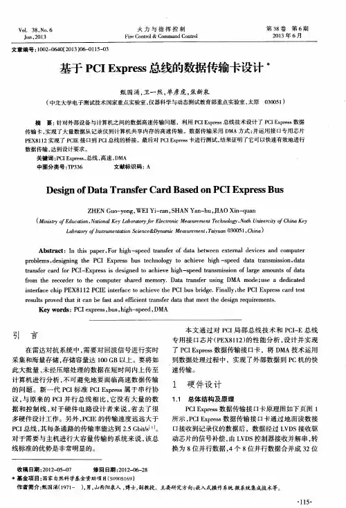
基于PCI Express总线的高速数据传输卡设计地面测控系统由上位机软件、工业控制计算机、地面控制台及相应电缆网组成。
在系统联试前它可以和采编器、存储器构成闭环反馈,对采编器、存储器实施自检。
地面控制台在上位机软件的控制下,真实模拟机上接口信号,为采编器提供不同的数字量信号,并对回收后的存储器进行数据的读取分析。
以前地面测试系统中的上位机软件系统和地面控制台之间的通信是由USB接口来完成的,传输速率较低。
为了解决大容量数据高速读取的瓶颈问题,采用P地面测控系统由上位机软件、工业控制计算机、地面控制台及相应电缆网组成。
在系统联试前它可以和采编器、存储器构成闭环反馈,对采编器、存储器实施自检。
地面控制台在上位机软件的控制下,真实模拟机上接口信号,为采编器提供不同的数字量信号,并对回收后的存储器进行数据的读取分析。
以前地面测试系统中的上位机软件系统和地面控制台之间的通信是由USB接口来完成的,传输速率较低。
为了解决大容量数据高速读取的瓶颈问题,采用PCI Express总线来读取数据。
PCI Express 采用了目前业内流行的点对点串行连接, 每个设备都有自己的专用连接, 不需要向整个总线请求带宽, 而且可以把数据传输率提高到一个很高的频率, 达到 USB 所不能提供的高带宽。
本文设计并实现的数据传输卡基于PCI Express总线,提高了系统的读写速度,满足了目前大容量高速实时传输记录的要求。
1 系统结构地面控制台是模拟机上信号源功能,信号源由上位机生成,然后下载到地面控制台的RAM中。
为了正确地发送信号源数据需要对下载的信号源数据进行自检,即将地面控制台RAM中的数据读入上位机来验证控制台中信号源是否正确。
本系统通过PCI Express传输卡实现了信号源自检功能。
如图1所示,上位机通过PCI Express接口将信号源的数据下载到FIFO1存储器当中,同时将相应的控制命令发送给FPGA。
FPGA检测到相应控制命令后,开始读取FIFO1中的数据,并将该数据经过串并转换写到地面控制台RAM中。
基于PCIe总线的专用高速信号采集卡设计林连雷;易宇【摘要】In some radar countermeasure tests,a high-speed signal acquisition system was designed to assess the test re-sults accurately. This system has the maximum sampling rate of 500 MS/s,in which the cache in the card is 1 GB,and can pro-vide data transmission interface of high-speed storage system to expand the storage capacity. Two operation modes of the scope operating mode and the continuous acquisition mode are offered in this system,and users can use the different operating modes according to the requirements to process the collected data. This system has perfect trigger function,and is convenience for the users to analyze the data.%在某些雷达对抗试验中,为了精确地评估试验效果,设计了一个高速信号采集系统,该系统具有最高为500 MS/s的采样率,板上缓存为1 GB,同时提供与高速存储系统的数据传输接口以供外扩存储容量.该系统提供了示波器工作模式和连续采集工作模式两种工作模式,用户可根据需求使用不同的工作模式对采集到的数据进行处理,同时该系统具有完善的触发功能,以方便用户对数据进行分析.【期刊名称】《现代电子技术》【年(卷),期】2015(038)021【总页数】5页(P52-55,59)【关键词】PCIExpress;高速数据采集;模拟信号;同步脉冲信号【作者】林连雷;易宇【作者单位】哈尔滨工业大学自动化测试与控制系,黑龙江哈尔滨 150001;哈尔滨工业大学自动化测试与控制系,黑龙江哈尔滨 150001【正文语种】中文【中图分类】TN911.7-34在某些雷达对抗试验中,为了精确地评估试验效果,需要对雷达接收机产生的回波信号、同步脉冲信号等进行采集,通过对这些信号的分析得出试验结果,基于此目的,需要设计一个具有高速采集能力的系统,用于采集雷达接收机产生的回波信号、同步脉冲信号;同时该系统需要具备大容量存储能力,用于实时存储采集到的数据,为雷达对抗试验后续的数据分析提供数据来源;为了更好地捕捉雷达对抗试验中的关键信号,该系统应该具备完善的触发功能。
基于PCIe总线高速数据传输系统的设计与实现的开题报告一、选题背景随着现代科技的飞速发展,数据处理和传输变得越来越重要。
不仅需要高效的数据传输速度以满足现代大数据处理的需要,也需要高可靠性和兼容性以适应不同应用场景的需求。
PCI Express(PCIe)总线技术由于其高速、可靠和广泛的应用支持而成为了一种重要的数据传输标准。
本课题基于此,旨在设计和实现一个基于PCIe总线的高速数据传输系统。
二、研究目的和意义本课题主要研究基于PCIe总线的高速数据传输系统的设计和实现,旨在提供一个具有高速、可靠、兼容性好的数据传输方案,以满足现代数据处理需求。
其意义在于:1. 提高数据处理效率。
PCIe总线技术具有高速传输和低延迟的特点,在大数据处理和高性能计算中能够显著提高数据传输效率。
2. 提高数据传输可靠性。
PCIe总线技术具有高可靠性的特点,其锁定机制和CRC校验功能能够保证数据传输的准确性和完整性。
3. 提高数据传输兼容性。
PCIe总线技术是一种广泛应用的数据传输标准,被应用于各种不同的领域,能够实现不同设备之间的数据交换和共享。
三、研究内容和研究方法本课题的主要研究内容包括:1. 设计一个符合PCIe总线规范的高速数据传输系统。
包括硬件电路设计和软件控制程序设计。
2. 实现高速数据传输系统,采用HDL语言设计硬件电路,采用C++设计软件控制程序。
3. 测试和验证高速数据传输系统,包括性能测试、稳定性测试和兼容性测试等。
本课题研究采用的方法主要包括:1. 系统设计方法。
根据PCIe总线规范,设计一个符合标准的高速数据传输系统,保证系统的性能、稳定性和兼容性。
2. 硬件设计方法。
采用HDL语言设计系统的硬件电路,包括PCIe 总线接口电路、数据传输电路和控制逻辑电路等。
3. 软件设计方法。
采用C++设计软件控制程序,包括系统的控制逻辑和数据传输协议等。
4. 测试和验证方法。
对系统进行性能测试、稳定性测试和兼容性测试等,以验证系统的可靠性和兼容性。
基于PCIe总线的超高速信号采集卡的设计摘要:设计一种基于PCIe 总线的不间断采样和传输的超高速数据采集卡。
利用双400MHz、14 位AID 转换器实现了800 MHz、14 位的信号高速、高精度采集,论述了利用Xilinx 公司FPGA 的IPCORE 设计实现PCIe 总线控制接口。
基于PCIe 总线,采用乒乓交换数据传输的机制,实现了高速采样数据流的不间断传输。
最后给出了实际采集数据的频谱。
利用该采集卡构成的数据采集系统在雷达侦察和干扰领域拥有很高的实用价值和广阔的应用前景。
关键词:数据采集;PCIe;FPGA;雷达对抗在雷达对抗系统中,需要对于雷达信号进行实时测频,并可以对感兴趣的信号进行储频,为假目标欺骗干扰或压制干扰提供测频结果和储频数据。
而数字测频是当今发展最快的测频技术之一。
数字测频、储频的关键技术之一即是超高速、高精度、不间断的信号采集技术。
采样速率和精度的不断提高,使得数据传输和存储越来越成为数据采集系统的技术瓶颈。
目前大部分高性能数据采集卡都是基于PCI、CPCI、VME 等总线,最高持续传输速率难以超过400 MB/s,因此大多数采集卡采用采集和存储分时工作的模式,即在板内设有一定容量的存储器,当存储器存储数据到一定量时,停止采集而开始上传数据,上传完毕后再重新启动采集,不断循环,文献也提出采集传输的流水工作模式,提高采集的效率。
这些工作方式虽然也能满足大部分数据采集的要求,但是在信号非常密集的环境中,交替工作模式将导致侦察截获概率降低,带来干扰的效能下降。
基于上述原因,本文论述了一种基于PCIe 总线的数据采集卡,该采集卡不但可以达到800 MHz/s 采样率、14 bit 采样精度,还具有不间断采集、实时上传的能力(在测频只取其中8 位分辨力,储频时取14 位分辨力,根据系统的总数据量可编程)。
该采集卡可以与高速信号处理器配合使用,构成信道化。
基于PCI总线的高速通信系统设计与实现的开题报告一、研究背景随着计算机技术的不断发展,人们对高速数据传输的需求越来越强烈。
PCI总线是一种高速通信接口标准,被广泛应用于计算机系统中,例如网卡、显卡、存储控制器等,可以实现高速数据传输,并且极大地提高了计算机系统的性能和效率。
本课题将基于PCI总线,利用Verilog HDL语言设计和实现一套高速通信系统。
在此基础上,将研究数据传输的稳定性、效率、协议等方面的问题,并通过实验验证系统的性能和可靠性。
二、研究内容1. PCI总线的工作原理和通信协议研究;2. 设计高速通信系统所需的硬件电路;3. 利用Verilog HDL语言进行电路设计和仿真;4. 验证系统的性能和可靠性。
三、研究目标1. 实现基于PCI总线的高速通信系统;2. 提高数据传输的稳定性和效率;3. 研究通信协议的优化和改进;4. 验证系统的性能和可靠性,达到商用水平。
四、研究方法和实验方案1. 理论分析和文献调研:通过阅读相关的学术论文和研究文献,深入了解PCI总线的工作原理和通信协议;2. 硬件电路设计:根据理论分析和文献调研结果,设计高速通信系统所需的硬件电路,并进行仿真验证;3. Verilog HDL设计:根据硬件电路设计结果,使用Verilog HDL语言进行电路设计和仿真;4. 实验验证:实现设计后的高速通信系统,通过实验验证系统的性能和可靠性,并对系统的稳定性、效率、协议等方面进行分析和改进。
五、预期成果1. 完成基于PCI总线的高速通信系统的设计和实现;2. 提高数据传输的稳定性和效率;3. 提出通信协议的改进建议;4. 验证系统的性能和可靠性,达到商用水平;5. 发表学术论文1篇。
基于PCI总线的高速数据采集卡系统设计与实现裴喜龙(信息工程大学郑州450002)摘要:本文介绍一种基于PCI总线的高速数据采集卡系统的设计方法,讨论了设计高速数据采集系统的关键技术,给出了系统整体设计方案和PCI接口通信方式,完成了采集卡设备驱动程序及其应用程序的实现。
关键词:PCI总线数据采集卡设备驱动应用程序中图分类号:TP393.03。
Design and Implement of A High speed Data Acquisition Card Based on PCI BusPei Xilong(Information Engineering University, Zhengzhou 450002, China) Abstract: In this article, we introduce a method of how to design a high speed data acquisition card based on PCI bus, discuss pivotal technique about this system and the communication of the PCI interface, propose the whole design project and the develop the device driver and realize the app.Keywords: PCI BUS Data Acquisition Card Device Driver App1.引言数据采集技术是现代信号处理的基础,广泛应用于雷达、通信、遥测遥感等领域。
在数字信号处理工作中,实现对所需数据高速、实时、大批量采集具有重要意义。
随着信息科学的飞速发展,人们面临的信号处理任务愈来愈繁重,对数据采集系统的要求也愈来愈高。
利用PC机作为数据采集的平台,通过数据总线将采集的数据高速传输到PC机内存中,是实现采集系统数据存储的有效手段。
PCI-Express总线介绍接口设计和实现PCI Express总线是新一代的I/O局部总线标准,是取代PCI总线的革命性总线架构。
PCI总线曾经是PC体系结构发展史上的一个里程碑,但是随着技术的不断发展,新涌现出的一些外部设备对传输速度和带宽有更高的要求,PCI设计之初并没有考虑这些因素,因此并不能完全满足这些外部设备的需求。
PCI Express总线正是在这种背景下应运而生的。
一个PCI Express连接可以被配置成x1、x2、x4、x8、x12、x16和x32的数据带宽。
Xilinx 公司的Virtex5系列FPGA芯片内嵌PCI-Express-Endpoint BLOCk硬核,为实现单片可配置PCI-Express总线解决方案提供了可能。
本文在研究PCI-Express接口协议和PCI-Express Endpoint Block硬核的基础上,使用Virtex5LXT系列的XC5VLX50T FPGA芯片设计PCI- Express接口硬件电路,现YPCI-Express x4总线数据的传输。
1 PCI-Express总线概述PCI-Express是一种高性能、通用的I/O互连技术,可以广泛应用于计算和通讯的平台。
与传统的PCI/PCI-X总线相比,PCI Express用高速串行接口替代了PCI-X的并行接口;用点到点的基于Switch的交换式通讯替代了PCI-X的基于总线的通讯;用基于包的传输协议(PACketbasedprotocol)替代TPCI-X的基于总线的传输协议。
此外,它还引入了一些新的特性:更强的电源管理、服务质量控制(QoS),支持热拔插,以及完善的错误处理和恢复。
1.1 PCI-Express设备/拓扑结构PCI-Express的典型拓扑结构如图1所示。
PCI-Express协议中共定义了三种设备:RootComplex、Endpoint和Switeh。
Root Complex在系统中的位置类似于PCI-X中的主桥,它是I/O层次的根,它将CPU和MM连接至I/O部件。