计算流体动力学和动态耦合热力学毕业论文中英文资料外文翻译文献
- 格式:doc
- 大小:1.65 MB
- 文档页数:29

外文出处:Ellekilde, L. -., & Christensen, H. I. (2009). Control of mobile manipulator using the dynamical systems approach. Robotics and Automation, Icra 09, IEEE International Conference on (pp.1370 - 1376). IEEE.机械臂动力学与控制的研究拉斯彼得Ellekilde摘要操作器和移动平台的组合提供了一种可用于广泛应用程序高效灵活的操作系统,特别是在服务性机器人领域。
在机械臂众多挑战中其中之一是确保机器人在潜在的动态环境中安全工作控制系统的设计。
在本文中,我们将介绍移动机械臂用动力学系统方法被控制的使用方法。
该方法是一种二级方法, 是使用竞争动力学对于统筹协调优化移动平台以及较低层次的融合避障和目标捕获行为的方法。
I介绍在过去的几十年里大多数机器人的研究主要关注在移动平台或操作系统,并且在这两个领域取得了许多可喜的成绩。
今天的新挑战之一是将这两个领域组合在一起形成具有高效移动和有能力操作环境的系统。
特别是服务性机器人将会在这一方面系统需求的增加。
大多数西方国家的人口统计数量显示需要照顾的老人在不断增加,尽管将有很少的工作实际的支持他们。
这就需要增强服务业的自动化程度,因此机器人能够在室内动态环境中安全的工作是最基本的。
图、1 一台由赛格威RMP200和轻重量型库卡机器人组成的平台这项工作平台用于如图1所示,是由一个Segway与一家机器人制造商制造的RMP200轻机器人。
其有一个相对较小的轨迹和高机动性能的平台使它适应在室内环境移动。
库卡工业机器人具有较长的长臂和高有效载荷比自身的重量,从而使其适合移动操作。
当控制移动机械臂系统时,有一个选择是是否考虑一个或两个系统的实体。
在参考文献[1]和[2]中是根据雅可比理论将机械手末端和移动平台结合在一起形成一个单一的控制系统。
毕业论文外文文献翻译译文题目:INTEGRATION OF MACHINERY外文资料翻译资料来源:文章名:INTEGRATION OF MACHINERY 《Digital Image Processing》书刊名:作者:Y. Torres J. J. Pavón I. Nieto and J. A.Rodríguez章节:2.4 INTEGRATION OF MACHINERYINTEGRATION OF MACHINERY (From ELECTRICAL AND MACHINERY INDUSTRY)ABSTRACT Machinery was the modern science and technology development inevitable resultthis article has summarized the integration of machinery technology basic outlineand the development background .Summarized the domestic and foreign integration ofmachinery technology present situation has analyzed the integration of machinerytechnology trend of development. Key word:integration of machinery ,technology,present situation ,productt,echnique of manufacture ,trend of development 0. Introduction modern science and technology unceasing development impelleddifferent discipline intersecting enormously with the seepage has caused the projectdomain technological revolution and the transformation .In mechanical engineeringdomain because the microelectronic technology and the computer technology rapiddevelopment and forms to the mechanical industry seepage the integration of machinerycaused the mechanical industry the technical structure the product organizationthe function and the constitution the production method and the management systemhas had the huge change caused the industrial production to enter into quottheintegration of machineryquot by quotthe machinery electrificationquot for the characteristicdevelopment phase. 1. Integration of machinery outline integration of machinery is refers in theorganization new owner function the power function in the information processingfunction and the control function introduces the electronic technology unifies thesystem the mechanism and the computerization design and the software whichconstitutes always to call. The integration of machinery development also has becomeone to have until now own system new discipline not only develops along with thescience and technology but also entrusts with the new content .But its basiccharacteristic may summarize is: The integration of machinery is embarks from thesystem viewpoint synthesis community technologies and so on utilization mechanicaltechnology microelectronic technology automatic control technology computertechnology information technology sensing observation and control technologyelectric power electronic technology connection technology information conversiontechnology as well as software programming technology according to the systemfunction goal and the optimized organization goal reasonable disposition and thelayout various functions unit in multi-purpose high grade redundant reliable inthe low energy consumption significance realize the specific function value andcauses the overall system optimization the systems engineering technology .From thisproduces functional system then becomes an integration of machinery systematic orthe integration of machinery product. Therefore quotintegration of machineryquot coveringquottechnologyquot and quotproductquot two aspects .Only is the integration of machinerytechnology is based on the above community technology organic fusion one kind ofcomprehensivetechnology but is not mechanical technical the microelectronictechnology as well as other new technical simple combination pieces together .Thisis the integration of machinery and the machinery adds the machinery electrificationwhich the electricity forms in the concept basic difference .The mechanicalengineering technology has the merely technical to develop the machineryelectrification still was the traditional machinery its main function still wasreplaces with the enlargement physical strength .But after develops the integrationof machinery micro electron installment besides may substitute for certainmechanical parts the original function but also can entrust with many new functionslike the automatic detection the automatic reduction information demonstrate therecord the automatic control and the control automatic diagnosis and the protectionautomatically and so on .Not only namely the integration of machinery product ishumans hand and body extending humans sense organ and the brains look has theintellectualized characteristic is the integration of machinery and the machineryelectrification distinguishes in the function essence. 2. Integration of machinery development condition integration of machinerydevelopment may divide into 3 stages roughly.20th century 60s before for the firststage this stage is called the initial stage .In this time the people determinationnot on own initiative uses the electronic technology the preliminary achievement toconsummate the mechanical product the performance .Specially in Second World Warperiod the war has stimulated the mechanical product and the electronic technologyunion these mechanical and electrical union military technology postwar transferscivilly to postwar economical restoration positive function .Developed and thedevelopment at that time generally speaking also is at the spontaneouscondition .Because at that time the electronic technology development not yetachieved certain level mechanical technical and electronic technology union alsonot impossible widespread and thorough development already developed the productwas also unable to promote massively. The 20th century 7080 ages for the second stagemay be called the vigorous development stage .This time the computer technologythe control technology the communication development has laid the technology basefor the integration of machinery development . Large-scale ultra large scaleintegrated circuit and microcomputer swift and violent development has provided thefull material base for the integration of machinery development .This timecharacteristic is :①A mechatronics word first generally is accepted in Japanprobably obtains the quite widespread acknowledgment to 1980s last stages in theworldwide scale ②The integration of machinery technology and the product obtainedthe enormous development ③The various countries start to the integration ofmachinery technology and the product give the very big attention and the support.1990s later periods started the integration of machinery technology the new stagewhich makes great strides forward to the intellectualized direction the integrationof machinery enters the thorough development time .At the same time optics thecommunication and so on entered the integration of machinery processes thetechnology also zhan to appear tiny in the integration of machinery the footappeared the light integration of machinery and the micro integration of machineryand so on the new branch On the other hand to the integration ofmachinery systemmodeling design the analysis and the integrated method the integration ofmachinery discipline system and the trend of development has all conducted thethorough research .At the same time because the hugeprogress which domains and so on artificial intelligence technology neural networktechnology and optical fiber technology obtain opened the development vast worldfor the integration of machinery technology .These research will urge theintegration of machinery further to establish the integrity the foundation and formsthe integrity gradually the scientific system. Our country is only then starts fromthe beginning of 1980s in this aspect to study with the application .The State Councilhad been established the integration of machinery leading group and lists as quot863plansquot this technology .When formulated quot95quot the plan and in 2010 developed thesummary had considered fully on international the influence which and possiblybrought from this about the integration of machinery technology developmenttrend .Many universities colleges and institutes the development facility and somelarge and middle scale enterprises have done the massive work to this technicaldevelopment and the application does not yield certain result but and so on theadvanced countries compared with Japan still has the suitable disparity. 3. Integration of machinery trend of development integrations of machinery arethe collection machinery the electron optics the control the computer theinformation and so on the multi-disciplinary overlapping syntheses its developmentand the progress rely on and promote the correlation technology development and theprogress .Therefore the integration of machinery main development direction is asfollows: 3.1 Intellectualized intellectualizations are 21st century integration ofmachinery technological development important development directions .Theartificial intelligence obtains day by day in the integration of machineryconstructors research takes the robot and the numerical control engine bedintellectualization is the important application .Here said quottheintellectualizationquot is to the machine behavior description is in the control theoryfoundation the absorption artificial intelligence the operations research thecomputer science the fuzzy mathematics the psychology the physiology and the chaosdynamics and so on the new thought the new method simulate the human intelligenceenable it to have abilities and so on judgment inference logical thinkingindependent decision-making obtains the higher control goal in order to .Indeedenable the integration of machinery product to have with the human identicalintelligence is not impossible also is nonessential .But the high performancethe high speed microprocessor enable the integration of machinery product to havepreliminary intelligent or humans partial intelligences then is completelypossible and essential. In the modern manufacture process the information has become the controlmanufacture industry the determining factor moreover is the most active actuationfactor .Enhances the manufacture system information-handling capacity to become themodern manufacture science development a key point .As a result of the manufacturesystem information organization and structure multi-level makes the information thegain the integration and the fusion presents draws up the character informationmeasuremulti-dimensional as well as information organizations multi-level .In themanufacture information structural model manufacture information uniform restraintdissemination processing and magnanimous data aspects and so on manufacture knowledgelibrary management all also wait for further break through. Each kind of artificial intelligence tool and the computation intelligence methodpromoted the manufacture intelligence development in the manufacture widespreadapplication .A kind based on the biological evolution algorithm computationintelligent agent in includes thescheduling problem in the combination optimization solution area of technologyreceives the more and more universal attention hopefully completes the combinationoptimization question when the manufacture the solution speed and the solutionprecision aspect breaks through the question scale in pairs the restriction .Themanufacture intelligence also displays in: The intelligent dispatch the intelligentdesign the intelligent processing the robot study the intelligent control theintelligent craft plan the intelligent diagnosis and so on are various These question key breakthrough may form the product innovation the basicresearch system. Between 2 modern mechanical engineering front science differentscience overlapping fusion will have the new science accumulation the economicaldevelopment and societys progress has had the new request and the expectation tothe science and technology thus will form the front science .The front science alsohas solved and between the solution scientific question border area .The front sciencehas the obvious time domain the domain and the dynamic characteristic .The projectfront science distinguished in the general basic science important characteristicis it has covered the key science and technology question which the project actualappeared. Manufacture system is a complex large-scale system for satisfies the manufacturesystem agility the fast response and fast reorganization ability must profit fromthe information science the life sciences and the social sciences and so on themulti-disciplinary research results the exploration manufacture system newarchitecture the manufacture pattern and the manufacture system effectiveoperational mechanism .Makes the system optimization the organizational structureand the good movement condition is makes the system modeling the simulation andthe optimized essential target .Not only the manufacture system new architecture tomakes the enterprise the agility and may reorganize ability to the demand responseability to have the vital significance moreover to made the enterprise first floorproduction equipment the flexibility and may dynamic reorganization ability set ahigher request .The biological manufacture view more and more many is introduced themanufacture system satisfies the manufacture system new request. The study organizes and circulates method and technique of complicated systemfrom the biological phenomenon is a valid exit which will solve many hard nut tocracks that manufacturing industry face from now on currently .Imitating to livingwhat manufacturing point is mimicry living creature organ of from the organizationfrom match more from growth with from evolution etc. function structure and circulatemode of a kind of manufacturing system and manufacturing process. The manufacturing drives in the mechanism under continuously by ones ownperfect raise on organizing structure and circulating modeand thus to adapt theprocess ofwith ability for the environment .For from descend but the last productproceed together a design and make a craft rules the auto of the distance born producesystem of dynamic state reorganization and product and manufacturing the system tendautomatically excellent provided theories foundation and carry out acondition .Imitate to living a manufacturing to belong to manufacturing science andlife science ofquotthe far good luck is miscellaneous to hand overquot it will produceto the manufacturing industry for 21 centuries huge of influence .机电一体化摘要机电一体化是现代科学技术发展的必然结果本文简述了机电一体化技术的基本概要和发展背景。
计算流体动力学(CFD)分析概述No BoundariesANSYS/FLOTRAN分析指南第一章 FLOTRAN 计算流体动力学(CFD)分析概述FLOTRAN CFD 分析的概念ANSYS程序中的FLOTRAN CFD分析功能是一个用于分析二维及三维流体流动场的先进的工具,使用ANSYS中用于FLOTRAN CFD分析的FLUID 141和FLUID 142 单元,可解决如下问题:, 作用于气动翼(叶)型上的升力和阻力, 超音速喷管中的流场, 弯管中流体的复杂的三维流动同时,FLOTRAN还具有如下功能:, 计算发动机排气系统中气体的压力及温度分布, 研究管路系统中热的层化及分离, 使用混合流研究来估计热冲击的可能性, 用自然对流分析来估计电子封装芯片的热性能, 对含有多种流体的(由固体隔开)热交换器进行研究FLOTRAN 分析的种类FLOTRAN可执行如下分析:, 层流或紊流, 传热或绝热, 可压缩或不可压缩, 牛顿流或非牛顿流, 多组份传输这些分析类型并不相互排斥,例如,一个层流分析可以是传热的或者是绝热的,一个紊流分析可以是可压缩的或者是不可压缩的。
层流分析层流中的速度场都是平滑而有序的,高粘性流体(如石油等)的低速流动就通常是层流。
紊流分析紊流分析用于处理那些由于流速足够高和粘性足够低从而引起紊流波动的流体流动情况,ANSYS中的二方程紊流模型可计及在平均流动下的紊流速度波动的影响。
如果流体的密度在流动过程中保持不变或者当流体压缩时只消耗很少的能量,该流体就可认为是不可压缩的,不可压缩流的温度方程将忽略流体动能的变化和粘性耗散。
热分析流体分析中通常还会求解流场中的温度分布情况。
如果流体性质不随温度而变,就可不解温度方程。
在共轭传热问题中,要在同时包含流体区域和非流体区域(即固1No BoundariesANSYS/FLOTRAN分析指南体区域)的整个区域上求解温度方程。
在自然对流传热问题中,流体由于温度分布的不均匀性而导致流体密度分布的不均匀性,从而引起流体的流动,与强迫对流问题不同的是,自然对流通常都没有外部的流动源。
参考文献中文的英文对照在学术论文中,参考文献是非常重要的一部分,它可以为论文的可信度和学术性增添分数,其中包括中文和英文文献。
以下是一些常见的参考文献中文和英文对照:1. 书籍 Book中文:王小明. 计算机网络技术. 北京:清华大学出版社,2018.英文:Wang, X. Computer Network Technology. Beijing: Tsinghua University Press, 2018.2. 学术期刊 Article in Academic Journal中文:张婷婷,李伟. 基于深度学习的影像分割方法. 计算机科学与探索,2019,13(1):61-67.英文:Zhang, T. T., Li, W. Image Segmentation Method Based on Deep Learning. Computer Science and Exploration, 2019, 13(1): 61-67.3. 会议论文 Conference Paper中文:王维,李丽. 基于云计算的智慧物流管理系统设计. 2019年国际物流与采购会议论文集,2019:112-117.英文:Wang, W., Li, L. Design of Smart Logistics Management System Based on Cloud Computing. Proceedings of the 2019 International Conference on Logistics and Procurement, 2019: 112-117.4. 学位论文 Thesis/Dissertation中文:李晓华. 基于模糊神经网络的水质评价模型研究. 博士学位论文,长春:吉林大学,2018.英文:Li, X. H. Research on Water Quality Evaluation Model Based on Fuzzy Neural Network. Doctoral Dissertation, Changchun: Jilin University, 2018.5. 报告 Report中文:国家统计局. 2019年国民经济和社会发展统计公报. 北京:中国统计出版社,2019.英文:National Bureau of Statistics. Statistical Communique of the People's Republic of China on the 2019 National Economic and Social Development. Beijing: China Statistics Press, 2019.以上是一些常见的参考文献中文和英文对照,希望对大家写作有所帮助。
计算流体力学英语—高频词汇计算流体力学英语abort 异常中断, 中途失败, 夭折, 流产, 发育不全,中止计划[任务] accidentally 偶然地, 意外地accretion 增长activation energy 活化能active center 活性中心addition 增加adjacent 相邻的aerosol浮质(气体中的悬浮微粒,如烟,雾等), [化]气溶胶, 气雾剂, 烟雾剂 ambient 周围的, 周围环境amines 胺amplitude 广阔, 丰富, 振幅, 物理学名词annular 环流的algebraic stress model(ASM) 代数应力模型algorithm 算法align 排列,使结盟, 使成一行alternately 轮流地analogy 模拟,效仿analytical solution 分析解anisotropic 各向异性的anthracite 无烟煤apparent 显然的, 外观上的,近似的approximation 近似arsenic 砷酸盐assembly 装配associate 联合,联系assume 假设assumption 假设atomization 油雾axial 轴向的battlement 城垛式biography 经历bituminous coal 烟煤blow-off water 排污水blowing devices 鼓风(吹风)装置body force 体积力boiler plant 锅炉装置(车间)Boltzmain 玻耳兹曼Brownian rotation 布朗转动bulk 庞大的bulk density 堆积密度burner assembly 燃烧器组件burnout 燃尽capability 性能,(实际)能力,容量,接受力carbon monoxide COcarbonate 碳酸盐carry-over loss 飞灰损失Cartesian 迪卡尔坐标的casing 箱,壳,套catalisis 催化channeled 有沟的,有缝的char 焦炭、炭circulation circuit 循环回路circumferential velocity 圆周速度clinkering 熔渣clipped 截尾的clipped Gaussian distribution 截尾高斯分布closure (模型的)封闭cloud of particles 颗粒云cluster 颗粒团coal off-gas 煤的挥发气体coarse 粗糙的coarse grid 疏网格,粗网格coaxial 同轴的coefficient of restitution 回弹系数;恢复系数coke 碳collision 碰撞competence 能力competing process 同时发生影响的competing-reactions submodel 平行反应子模型component 部分分量composition 成分cone shape 圆锥体形状configuration 布置,构造confined flames 有界燃烧confirmation 证实, 确认, 批准conservation 守恒不灭conservation equation 守恒方程conserved scalars 守恒量considerably 相当地consume 消耗contact angle 接触角contamination 污染contingency 偶然, 可能性, 意外事故, 可能发生的附带事件continuum 连续体converged 收敛的conveyer 输运机dead zones 死区decompose 分解decouple 解藕的defy 使成为不可能demography 统计deposition 沉积derivative with respect to 对…的导数derivation 引出, 来历, 出处, (语言)语源, 词源design cycle 设计流程desposit 积灰,结垢deterministic approach 确定轨道模型deterministic 宿命的deviation 偏差devoid 缺乏devolatilization 析出挥发分,液化作用diffusion 扩散diffusivity 扩散系数digonal 二角(的), 对角的,二维的dilute 稀的diminish 减少direct numerical simulation 直接模拟discharge 释放discrete 离散的discrete phase 分散相, 不连续相discretization [数]离散化deselect 取消选定dispersion 弥散dissector 扩流锥dissociate thermally 热分解dissociation 分裂dissipation 消散, 分散, 挥霍, 浪费, 消遣, 放荡, 狂饮 distributionof air 布风divide 除以dot line 虚线drag coefficient 牵引系数,阻力系数drag and drop 拖放drag force 曳力drift velocity 漂移速度driving force 驱[传, 主]动力droplet 液滴drum 锅筒dry-bottom-furnace 固态排渣炉dry-bottom 冷灰斗,固态排渣duct 管dump 渣坑dust-air mixture 一次风EBU---Eddy break up 漩涡破碎模型eddy 涡旋effluent 废气,流出物elastic 弹性的electro-staic precipitators 静电除尘器emanate 散发, 发出, 发源,[罕]发散, 放射embrasure 喷口,枪眼emissivity [物]发射率empirical 经验的endothermic reaction 吸热反应enhance 增,涨enlarge 扩大ensemble 组,群,全体enthalpy 焓entity 实体entrain 携带,夹带entrained-bed 携带床equilibrate 保持平衡equilibrium 化学平衡ESCIMO-----Engulfment(卷吞)Stretching(拉伸)Coherence(粘附)Interdiffusion-interaction(相互扩散和化学反应) Moving-observer(运动观察者)exhaust 用尽, 耗尽, 抽完, 使精疲力尽排气排气装置用不完的, 不会枯竭的exit 出口,排气管exothermic reaction 放热反应expenditure 支出,经费expertise 经验explicitly 明白地, 明确地extinction 熄灭的extract 抽出,提取evaluation 评价,估计,赋值evaporation 蒸发(作用)Eulerian approach 欧拉法facilitate 推动,促进factor 把…分解fast chemistry 快速化学反应fate 天数, 命运, 运气,注定, 送命,最终结果 feasible 可行的,可能的feed pump 给水泵feedstock 填料fine grid 密网格,细网格finite difference approximation 有限差分法 flamelet 小火焰单元flame stability 火焰稳定性flow pattern 流型fluctuating velocity 脉动速度fluctuation 脉动,波动flue 烟道(气)flue duck 烟道fluoride 氟化物fold 夹层块forced-and-induced draft fan 鼓引风机 forestall 防止fouling 沾污fraction 碎片部分,百分比 fragmentation 破碎fuel-lean flamefuel-rich regions 富燃料区,浓燃料区 fuse 熔化,熔融gas duct 烟道gas-tight 烟气密封gasification 气化(作用)gasifier 气化器generalized model 通用模型Gibbs function Method 吉布斯函数法 Gordon 戈登governing equation 控制方程gradient 梯度graphics 图gross efficiency 总效率hazard 危险header 联箱helically 螺旋形地heterogeneous 异相的heat flux 热流(密度)heat regeneration 再热器heat retention coeff 保热系数histogram 柱状图homogeneous 同相的、均相的hopper 漏斗horizontally 卧式的,水平的hydrodynamic drag 流体动力阻力hydrostatic pressure 静压hypothesis 假设humidity 湿气,湿度,水分含量identical 同一的,完全相同的ignition 着火illustrate 图解,插图in common with 和…一样in excess of 超过, 较...为多in recognition of 承认…而,按照in terms of 根据, 按照, 用...的话, 在...方面 incandescent 白炽的,光亮的inception 起初induced-draft fan 强制引风机inert 无活动的, 惰性的, 迟钝的inert atmosphere 惰性气氛inertia 惯性, 惯量inflammability 可燃性injection 引入,吸引inleakage 漏风量inleakage 漏风量inlet 入口inlet vent 入烟口instantaneous reaction rate 瞬时反应速率instantaneous velocity 瞬时速度instruction 指示, 用法说明(书), 教育, 指导, 指令 intake fan 进气风扇integral time 积分时间integration 积分interface 接触面intermediate 中间的,介质intermediate species 中间组分intermittency model of turbulence 湍流间歇模型 intermixing 混合intersect 横断,相交interval 间隔intrinsic 内在的inverse proportion 反比irreverse 不可逆的irreversible 不可逆的,单向的isothermal 等温的, 等温线的,等温线isotropic 各向同性的joint 连接justify 认为Kelvin 绝对温度,开氏温度kinematic viscosity 动粘滞率, 动粘度kinetics 动力学Lagrangian approach 拉格朗日法laminarization 层流化的Laminar 层流Laminar Flamelet Concept 层流小火焰概念large-eddy simulation (LES) 大涡模拟leak 泄漏length scale 湍流长度尺度liberate 释放lifetime 持续时间,(使用)寿命,使用期 literature 文学(作品), 文艺, 著作, 文献lining 炉衬localized 狭小的logarithm [数] 对数Low Reynolds Number Modeling Method 低雷诺数模型macropore 大孔隙(直径大于1000埃的孔隙)manipulation 处理, 操作, 操纵, 被操纵mass action 质量作用mass flowrate 质量流率Mcbride 麦克布利德mean free paths 平均自由行程mean velocity 平均速度meaningful 意味深长的,有意义的medium 均匀介质mercury porosimetery 水银测孔计, 水银孔率计mill 磨碎,碾碎mineral matter 矿物质mixture fraction 混合分数modal 众数的,形式的, 样式的, 形态上的, 情态的, 语气的 [计](对话框等)模式的modulus 系数, 模数moisture 水分,潮湿度molar 质量的, [化][物]摩尔的moment 力矩,矩,动差momentum 动量momentum transfer 动量传递monobloc 单元机组monobloc units 单组mortar 泥灰浆mount 安装,衬底Monte Carlo methods 蒙特卡罗法multiflux radiation model 多(4/6)通量模型 multivariate [统][数]多变量的,多元的 negative 负Newton-Rephson 牛顿—雷夫森nitric oxide NO2node 节点non-linear 非线性的numerical control 数字控制numerical simulation 数值模拟table look-up scheme 查表法tabulate 列表tangential 切向的tangentially 切线tilting 摆动the heat power of furnace 热负荷the state-of-the-art 现状thermal effect 反应热thermodynamic 热力学thermophoresis 热迁移,热泳threshold 开始, 开端, 极限tortuosity 扭转, 曲折, 弯曲toxic 有毒的,毒的trajectory 轨迹,弹道tracer 追踪者, 描图者, (铁笔等)绘图工具translatory 平移的transport coefficients 输运系数transverse 横向,横线triatomic 三原子的turbulence intensity 湍流强度turbulent 湍流turbulent burner 旋流燃烧器turbulization 涡流turnaround 完成two-scroll burner 双涡流燃烧器unimodal [统](频率曲线或分布)单峰的,(现象或性质) 用单峰分布描述的 validate 使…证实validation 验证vaporization 汽化Variable 变量variance 方差variant 不同的,变量variation 变更, 变化, 变异, 变种, [音]变奏, 变调vertical 垂直的virtual mass 虚质量viscosity 粘度visualization 可视化volatile 易挥发性的volume fraction 体积分数, 体积分率, 容积率 volume heat 容积热vortex burner 旋流式燃烧器vorticity 旋量wall-function method 壁面函数法water equivalent 水当量weighting factor 权重因数unity (数学)一uniform 不均匀unrealistic 不切实际的, 不现实的Zeldovich 氮的氧化成一氧化氮的过程zero mean 零平均值zone method 区域法。
一种基于abaqus-starccm+的流固耦合计算方法1. 引言1.1 概述本篇文章介绍了一种基于ABAQUS和STAR-CCM+的流固耦合计算方法。
流固耦合问题是指涉及流体和固体之间相互作用的问题,如在液态金属凝固过程中的热传导和流动问题、风力发电机叶轮的气动力学行为等。
该方法结合ABAQUS 和STAR-CCM+两个强大的计算软件,通过将它们的优势互补起来,可以更准确地模拟和分析流固耦合问题。
1.2 文章结构本文共分为五个部分。
首先,在引言部分,我们会对本文进行概述,并介绍文章的结构。
其次,在第二部分中,我们将详细介绍ABAQUS和STAR-CCM+这两个软件及其功能和特点。
第三部分将给出对流固耦合问题的概述,包括定义以及应用领域。
接下来,在第四部分中,我们将详细介绍基于ABAQUS和STAR-CCM+的流固耦合计算方法,包括在这两个软件中采用的具体算法及其原理。
最后,在结论与展望部分,我们将总结文章得出的结果,并提出存在问题与改进方向。
1.3 目的本文的目的是介绍一种基于ABAQUS和STAR-CCM+的流固耦合计算方法。
通过本文的阐述,读者将了解到这两个软件在流固耦合问题中的应用及其计算方法,以及如何运用它们进行模拟和分析。
希望通过这篇文章的撰写和分享,能够推动流固耦合问题研究领域的发展,提供更准确可靠的计算方法,并为相关领域工程师和研究人员提供参考与借鉴。
2. ABAQUS和STAR-CCM+简介2.1 ABAQUS简介ABAQUS是由Dassault Systèmes公司开发的一种强大的有限元分析软件,广泛应用于工程结构分析领域。
它能够模拟和分析复杂的结构破坏、变形、疲劳寿命等行为,提供准确的数值解。
ABAQUS具有多种计算功能,包括线性和非线性分析、静态和动态分析、热力学和热传导分析等。
它支持各种材料类型的建模,如金属、塑料、复合材料等,并且可以考虑不同加载条件下的材料本构关系。
![污水处理化工毕业设计论文中英文外文资料文献翻译[管理资料]](https://uimg.taocdn.com/f0bd53e26edb6f1afe001f7a.webp)
附件1:外文资料翻译译文城市污水常温处理中的新型改良EGSB(膨胀颗粒污泥床)反应器的发展近年来,厌氧处理技术已经成为一项有吸引力的可持续发展的污水处理技术,因为它耗能少而且产气量少。
特别的,流式厌氧污泥床(UASB)和常规膨胀颗粒污泥床(EGSB)在城市污水处理中得到了广泛应运。
通常,EGSB比UASB 更能有效去除化学需氧量(COD),更能有效抵抗有机负荷率(OLR)、温度和pH 的变化。
然而,由于较高的上升流速和较多的甲烷气泡,使膨胀颗粒污泥床(EGSB)中的三相分离器中的水的流速很高,这就导致了大量生物质的流失,最终废水中的COD浓度就升高了。
所以,有时候不能满足城市污水处理厂或生物处理系统排放的标准,并导致生物处理系统崩溃。
因此,对与EGSB系统来说,城市污水处理中的关键问题是如何控制在高上升流速下的生物量流失。
在本文中,提出一种改进型的EGSB反应器模型,它结合了EGSB 和UASB 两者的优势。
在相同环境下通过比较,试验性地研究EGSB m和EGSB c两种反应器。
在东区污水处理厂中有一个初级出水沉降池。
在对膨胀颗粒污泥床(EGSB m)中水动力特征分析时,进行了停留时间分布(RTD)的实验和Polvmerase连锁反应实验,并且应用变性梯度凝胶电泳(PCR-DGGE)技术来探索颗粒污泥中微生物的多样性。
常温厌氧颗粒污泥取自中国无锡市的一家污水处理厂,该厂主要利用全比例内循环生物反应器处理酸性废水。
黑色的颗粒污泥有规则的形状(φ= - 2毫米)和良好的沉降性能。
污泥中含有悬浮固体(TSS)(VSS)59克/升。
在EGSB m 和EGSB c两种反应器中,最初的接种污泥量占有效总量的65%。
污水样本取自上海东区城市污水处理厂的一个初级沉淀池中。
其中包括60%生活污水和40%的工业废水。
污水的主要指标如表1。
表1 污水的主要指标工业生产中EGSBm和EGSBc反应器的原理图如图1。
两个反应器都是有机玻璃制成的,容量为300 升,采用连续流动模式。
cfx计算共轭传热英文回答:Conjugate heat transfer refers to the simultaneous transfer of heat between a solid body and a fluid medium. This phenomenon is commonly encountered in various engineering applications, such as cooling systems, heat exchangers, and combustion chambers. The understanding and analysis of conjugate heat transfer are crucial for designing efficient and reliable thermal systems.One approach to calculate conjugate heat transfer is by using the computational fluid dynamics (CFD) method. CFD is a numerical technique that solves the governing equations of fluid flow and heat transfer. In the case of conjugate heat transfer, the equations for fluid flow and heat transfer in the fluid domain and solid domain are coupled together.To perform a CFD simulation of conjugate heat transfer,the first step is to discretize the fluid and solid domains into smaller control volumes or finite elements. The governing equations, such as the Navier-Stokes equationsfor fluid flow and the heat conduction equation for solid, are then numerically solved within each control volume or finite element. The boundary conditions, such as the fluid velocity and temperature at the inlet and outlet, as wellas the solid surface temperature, need to be specified.The solution procedure involves iterating between the fluid and solid domains until convergence is achieved. In each iteration, the fluid properties, such as the density and viscosity, are updated based on the fluid temperature obtained from the previous iteration. The heat transfer between the fluid and solid is accounted for by considering the convective heat transfer coefficient and thetemperature difference between the fluid and solid surfaces.Conjugate heat transfer simulations can providevaluable insights into the heat transfer characteristicsand temperature distribution within a system. For example,in the design of a heat exchanger, the simulation resultscan help optimize the geometry and determine the required fluid flow rate to achieve the desired heat transfer rate. In a combustion chamber, the simulation can predict the temperature distribution on the solid walls and ensure that the materials can withstand the high temperatures.In addition to CFD, another approach to calculate conjugate heat transfer is through the use of analytical methods. Analytical solutions can be derived for simplified geometries and boundary conditions, allowing for a more straightforward and efficient calculation of heat transfer. However, analytical solutions are often limited toidealized scenarios and may not capture the complex flow and temperature patterns seen in real-world applications.In conclusion, conjugate heat transfer is a critical phenomenon in various engineering applications. The calculation of conjugate heat transfer can be performed using computational fluid dynamics or analytical methods. Both approaches have their advantages and limitations, and the choice of method depends on the specific problem and available resources.中文回答:共轭传热是指固体体和流体介质之间同时进行的热量传递。

中英文资料对照外文翻译水平轴风力发电机性能过渡,湍流和偏航的影响摘要最近出示的是改善的功能改善的混合动力车的的水平轴风力涡轮机(HAWT)配置Navier-Stokes势流建模方法。
研究的重点在三个问题上:湍流模型和转换模型,预测转子规定性能唤醒状态以及非轴向流(偏航)发电的影响,比较转子在国家可再生能源实验室(NREL)的测试与测量数据.简介水平轴风力涡轮机空气动力学的计算研究工作是在佐治亚理工学院进行。
本研究着重于了解影响风力涡轮机在非轴向和非均匀流入的流动机制的性能,也解决了高效的计算技术的发展,以补充现有的联合叶片元素动量理论方法。
这项工作是一个扩展的3-D的混合Navier-Stokes/potential流动求解,并已在佐治亚理工学院的水平轴风力发电机(HAWT)进行改善。
在这种方法中的三维非定常可压缩Navier-Stokes方程的解决只能在周围的转子叶片上的贴体网格这片一个很小的区域,。
远离叶片的和潜在的流动方程需要从叶片脱落的涡模拟涡细丝涡留下的Navier-Stokes地区的求解。
这些细丝自由对流的地方流动。
由于复杂的Navier-Stokes方程的计算只在附近的风力涡轮机叶片的地区,因此跟踪的涡利用拉格朗日方法,这是更有效的Navier-Stokes方程的方法级。
基本的Navier-Stokes方程混合势流的方法和其应用程序HAWT下轴流条件的记录在AIAA-99-0042(徐和Sankar,1999年).本研究范围本文介绍了近期的流动求解的增强功能和应用程序配置的兴趣。
增强集中在以下三个方面:过渡和湍流模型,物理一致唤醒建模,建模的偏航效果。
下文简要讨论这三个领域。
过渡和湍流的建模问题:研究两种湍流模型和两个过渡模型的预测性能影响的进行评估。
一个显示Spalart-Allmaras湍流方程湍流模型(书珥等,1998),另一个对基线鲍德温 - 洛马克斯零方程湍流模型进行了研究。
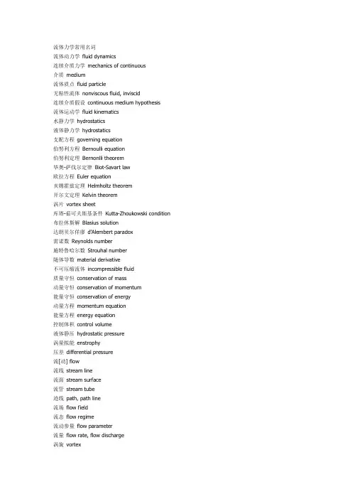
流体力学常用名词流体动力学fluid dynamics连续介质力学mechanics of continuous介质medium流体质点fluid particle无粘性流体nonviscous fluid, inviscid连续介质假设continuous medium hypothesis流体运动学fluid kinematics水静力学hydrostatics液体静力学hydrostatics支配方程governing equation伯努利方程Bernoulli equation伯努利定理Bernonlli theorem毕奥-萨伐尔定律Biot-Savart law欧拉方程Euler equation亥姆霍兹定理Helmholtz theorem开尔文定理Kelvin theorem涡片vortex sheet库塔-茹可夫斯基条件Kutta-Zhoukowski condition 布拉休斯解Blasius solution达朗贝尔佯廖d'Alembert paradox雷诺数Reynolds number施特鲁哈尔数Strouhal number随体导数material derivative不可压缩流体incompressible fluid质量守恒conservation of mass动量守恒conservation of momentum能量守恒conservation of energy动量方程momentum equation能量方程energy equation控制体积control volume液体静压hydrostatic pressure涡量拟能enstrophy压差differential pressure流[动] flow流线stream line流面stream surface流管stream tube迹线path, path line流场flow field流态flow regime流动参量flow parameter流量flow rate, flow discharge涡旋vortex涡量vorticity涡丝vortex filament涡线vortex line涡面vortex surface涡层vortex layer涡环vortex ring涡对vortex pair涡管vortex tube涡街vortex street卡门涡街Karman vortex street马蹄涡horseshoe vortex对流涡胞convective cell卷筒涡胞roll cell涡eddy涡粘性eddy viscosity环流circulation环量circulation速度环量velocity circulation偶极子doublet, dipole驻点stagnation point总压[力] total pressure总压头total head静压头static head总焓total enthalpy能量输运energy transport速度剖面velocity profile库埃特流Couette flow单相流single phase flow单组份流single-component flow均匀流uniform flow非均匀流nonuniform flow二维流two-dimensional flow三维流three-dimensional flow准定常流quasi-steady flow非定常流unsteady flow, non-steady flow 暂态流transient flow周期流periodic flow振荡流oscillatory flow分层流stratified flow无旋流irrotational flow有旋流rotational flow轴对称流axisymmetric flow不可压缩性incompressibility不可压缩流[动] incompressible flow浮体floating body定倾中心metacenter阻力drag, resistance减阻drag reduction表面力surface force表面张力surface tension毛细[管]作用capillarity来流incoming flow自由流free stream自由流线free stream line外流external flow进口entrance, inlet出口exit, outlet扰动disturbance, perturbation分布distribution传播propagation色散dispersion弥散dispersion附加质量added mass ,associated mass收缩contraction镜象法image method无量纲参数dimensionless parameter几何相似geometric similarity运动相似kinematic similarity动力相似[性] dynamic similarity平面流plane flow势potential势流potential flow速度势velocity potential复势complex potential复速度complex velocity流函数stream function源source汇sink速度[水]头velocity head拐角流corner flow空泡流cavity flow超空泡supercavity超空泡流supercavity flow空气动力学aerodynamics低速空气动力学low-speed aerodynamics 高速空气动力学high-speed aerodynamics 气动热力学aerothermodynamics亚声速流[动] subsonic flow跨声速流[动] transonic flow超声速流[动] supersonic flow锥形流conical flow楔流wedge flow叶栅流cascade flow非平衡流[动] non-equilibrium flow细长体slender body细长度slenderness钝头体bluff body钝体blunt body翼型airfoil翼弦chord薄翼理论thin-airfoil theory构型configuration后缘trailing edge迎角angle of attack失速stall脱体激波detached shock wave波阻wave drag诱导阻力induced drag诱导速度induced velocity临界雷诺数critical Reynolds number 前缘涡leading edge vortex附着涡bound vortex约束涡confined vortex气动中心aerodynamic center气动力aerodynamic force气动噪声aerodynamic noise气动加热aerodynamic heating离解dissociation地面效应ground effect气体动力学gas dynamics稀疏波rarefaction wave热状态方程thermal equation of state 喷管Nozzle普朗特-迈耶流Prandtl-Meyer flow瑞利流Rayleigh flow可压缩流[动] compressible flow可压缩流体compressible fluid绝热流adiabatic flow非绝热流diabatic flow未扰动流undisturbed flow等熵流isentropic flow匀熵流homoentropic flow兰金-于戈尼奥条件Rankine-Hugoniot condition 状态方程equation of state量热状态方程caloric equation of state完全气体perfect gas拉瓦尔喷管Laval nozzle马赫角Mach angle马赫锥Mach cone马赫线Mach line马赫数Mach number马赫波Mach wave当地马赫数local Mach number冲击波shock wave激波shock wave正激波normal shock wave斜激波oblique shock wave头波bow wave附体激波attached shock wave激波阵面shock front激波层shock layer压缩波compression wave反射reflection折射refraction散射scattering衍射diffraction绕射diffraction出口压力exit pressure超压[强] over pressure反压back pressure爆炸explosion爆轰detonation缓燃deflagration水动力学hydrodynamics液体动力学hydrodynamics泰勒不稳定性Taylor instability盖斯特纳波Gerstner wave斯托克斯波Stokes wave瑞利数Rayleigh number自由面free surface波速wave speed, wave velocity波高wave height波列wave train波群wave group波能wave energy表面波surface wave表面张力波capillary wave规则波regular wave不规则波irregular wave浅水波shallow water wave深水波deep water wave重力波gravity wave椭圆余弦波cnoidal wave潮波tidal wave涌波surge wave破碎波breaking wave船波ship wave非线性波nonlinear wave孤立子soliton水动[力]噪声hydrodynamic noise水击water hammer空化cavitation空化数cavitation number空蚀cavitation damage超空化流supercavitating flow水翼hydrofoil水力学hydraulics洪水波flood wave涟漪ripple消能energy dissipation海洋水动力学marine hydrodynamics 谢齐公式Chezy formula欧拉数Euler number弗劳德数Froude number水力半径hydraulic radius水力坡度hvdraulic slope高度水头elevating head水头损失head loss水位water level水跃hydraulic jump含水层aquifer排水drainage排放量discharge壅水曲线back water curve压[强水]头pressure head过水断面flow cross-section明槽流open channel flow孔流orifice flow无压流free surface flow有压流pressure flow缓流subcritical flow急流supercritical flow渐变流gradually varied flow急变流rapidly varied flow临界流critical flow异重流density current, gravity flow堰流weir flow掺气流aerated flow含沙流sediment-laden stream降水曲线dropdown curve沉积物sediment, deposit沉[降堆]积sedimentation, deposition沉降速度settling velocity流动稳定性flow stability不稳定性instability奥尔-索末菲方程Orr-Sommerfeld equation 涡量方程vorticity equation泊肃叶流Poiseuille flow奥辛流Oseen flow剪切流shear flow粘性流[动] viscous flow层流laminar flow分离流separated flow二次流secondary flow近场流near field flow远场流far field flow滞止流stagnation flow尾流wake [flow]回流back flow反流reverse flow射流jet自由射流free jet管流pipe flow, tube flow内流internal flow拟序结构coherent structure猝发过程bursting process表观粘度apparent viscosity运动粘性kinematic viscosity动力粘性dynamic viscosity泊poise厘泊centipoise厘沱centistoke剪切层shear layer次层sublayer流动分离flow separation层流分离laminar separation湍流分离turbulent separation分离点separation point附着点attachment point再附reattachment再层流化relaminarization起动涡starting vortex驻涡standing vortex涡旋破碎vortex breakdown涡旋脱落vortex shedding压[力]降pressure drop压差阻力pressure drag压力能pressure energy型阻profile drag滑移速度slip velocity无滑移条件non-slip condition壁剪应力skin friction, frictional drag壁剪切速度friction velocity磨擦损失friction loss磨擦因子friction factor耗散dissipation滞后lag相似性解similar solution局域相似local similarity气体润滑gas lubrication液体动力润滑hydrodynamic lubrication浆体slurry泰勒数Taylor number纳维-斯托克斯方程Navier-Stokes equation 牛顿流体Newtonian fluid边界层理论boundary later theory边界层方程boundary layer equation边界层boundary layer附面层boundary layer层流边界层laminar boundary layer湍流边界层turbulent boundary layer温度边界层thermal boundary layer边界层转捩boundary layer transition边界层分离boundary layer separation边界层厚度boundary layer thickness位移厚度displacement thickness动量厚度momentum thickness能量厚度energy thickness焓厚度enthalpy thickness注入injection吸出suction泰勒涡Taylor vortex速度亏损律velocity defect law形状因子shape factor测速法anemometry粘度测定法visco[si] metry流动显示flow visualization油烟显示oil smoke visualization孔板流量计orifice meter频率响应frequency response油膜显示oil film visualization阴影法shadow method纹影法schlieren method烟丝法smoke wire method丝线法tuft method 说明氢泡法nydrogen bubble method相似理论similarity theory相似律similarity law部分相似partial similarity定理pi theorem, Buckingham theorem静[态]校准static calibration动态校准dynamic calibration风洞wind tunnel激波管shock tube激波管风洞shock tube wind tunnel水洞water tunnel拖曳水池towing tank旋臂水池rotating arm basin扩散段diffuser测压孔pressure tap皮托管pitot tube普雷斯顿管preston tube斯坦顿管Stanton tube文丘里管Venturi tubeU形管U-tube压强计manometer微压计micromanometer多管压强计multiple manometer静压管static [pressure]tube流速计anemometer风速管Pitot- static tube激光多普勒测速计laser Doppler anemometer,laser Doppler velocimeter热线流速计hot-wire anemometer热膜流速计hot- film anemometer流量计flow meter粘度计visco[si] meter涡量计vorticity meter传感器transducer, sensor压强传感器pressure transducer热敏电阻thermistor示踪物tracer时间线time line脉线streak line尺度效应scale effect壁效应wall effect堵塞blockage堵寒效应blockage effect动态响应dynamic response响应频率response frequency底压base pressure菲克定律Fick law巴塞特力Basset force埃克特数Eckert number格拉斯霍夫数Grashof number努塞特数Nusselt number普朗特数prandtl number雷诺比拟Reynolds analogy施密特数schmidt number斯坦顿数Stanton number对流convection自由对流natural convection, free convec-tion 强迫对流forced convection热对流heat convection质量传递mass transfer传质系数mass transfer coefficient热量传递heat transfer传热系数heat transfer coefficient对流传热convective heat transfer辐射传热radiative heat transfer动量交换momentum transfer能量传递energy transfer传导conduction热传导conductive heat transfer热交换heat exchange临界热通量critical heat flux浓度concentration扩散diffusion扩散性diffusivity扩散率diffusivity扩散速度diffusion velocity分子扩散molecular diffusion沸腾boiling蒸发evaporation气化gasification凝结condensation成核nucleation计算流体力学computational fluid mechanics多重尺度问题multiple scale problem伯格斯方程Burgers equation对流扩散方程convection diffusion equationKDU方程KDV equation修正微分方程modified differential equation拉克斯等价定理Lax equivalence theorem数值模拟numerical simulation大涡模拟large eddy simulation数值粘性numerical viscosity非线性不稳定性nonlinear instability希尔特稳定性分析Hirt stability analysis相容条件consistency conditionCFL条件Courant- Friedrichs- Lewy condition ,CFL condition 狄里克雷边界条件Dirichlet boundary condition熵条件entropy condition远场边界条件far field boundary condition流入边界条件inflow boundary condition无反射边界条件nonreflecting boundary condition数值边界条件numerical boundary condition流出边界条件outflow boundary condition冯.诺伊曼条件von Neumann condition近似因子分解法approximate factorization method人工压缩artificial compression人工粘性artificial viscosity边界元法boundary element method配置方法collocation method能量法energy method有限体积法finite volume method流体网格法fluid in cell method,FLIC method通量校正传输法flux-corrected transport method通量矢量分解法flux vector splitting method伽辽金法Galerkin method积分方法integral method标记网格法marker and cell method, MAC method特征线法method of characteristics直线法method of lines矩量法moment method多重网格法multi- grid method板块法panel method质点网格法particle in cell method, PIC method质点法particle method预估校正法predictor-corrector method投影法projection method准谱法pseudo-spectral method随机选取法random choice method激波捕捉法shock-capturing method激波拟合法shock-fitting method谱方法spectral method稀疏矩阵分解法split coefficient matrix method不定常法time-dependent method时间分步法time splitting method变分法variational method涡方法vortex method隐格式implicit scheme显格式explicit scheme交替方向隐格式alternating direction implicit scheme, ADI scheme 反扩散差分格式anti-diffusion difference scheme紧差分格式compact difference scheme守恒差分格式conservation difference scheme克兰克-尼科尔森格式Crank-Nicolson scheme杜福特-弗兰克尔格式Dufort-Frankel scheme指数格式exponential scheme戈本诺夫格式Godunov scheme高分辨率格式high resolution scheme拉克斯-温德罗夫格式Lax-Wendroff scheme蛙跳格式leap-frog scheme单调差分格式monotone difference scheme保单调差分格式monotonicity preserving diffe-rence scheme穆曼-科尔格式Murman-Cole scheme半隐格式semi-implicit scheme斜迎风格式skew-upstream scheme全变差下降格式total variation decreasing scheme TVD scheme迎风格式upstream scheme , upwind scheme计算区域computational domain物理区域physical domain影响域domain of influence依赖域domain of dependence区域分解domain decomposition维数分解dimensional split物理解physical solution弱解weak solution黎曼解算子Riemann solver守恒型conservation form弱守恒型weak conservation form强守恒型strong conservation form散度型divergence form贴体曲线坐标body- fitted curvilinear coordi-nates [自]适应网格[self-] adaptive mesh适应网格生成adaptive grid generation自动网格生成automatic grid generation数值网格生成numerical grid generation交错网格staggered mesh网格雷诺数cell Reynolds number数植扩散numerical diffusion数值耗散numerical dissipation数值色散numerical dispersion数值通量numerical flux放大因子amplification factor放大矩阵amplification matrix阻尼误差damping error离散涡discrete vortex熵通量entropy flux熵函数entropy function分步法fractional step method。
CFD应用实例黄心权王东马亦忱张姜沈少琦2011届同济大学化学系化工专业摘要:计算流体动力学(CFD)是一种以流体为研究对象的数值模拟技术。
相对于实验流体动力学而言,它具有资金投入少、计算速度快、信息完备且不受模型尺寸限制等优点。
因此是研究流体动力学有力的工具。
本文主要介绍CDF的应用实例。
关键词:计算流体力学;画图;计算Application examples of CFDHuangXinQuan,WangDong,MaYiChen,ShenShaoQiChemical engineering and technology of TongJi UniversityAbstract:CFD is a kind of numerical simulation technology which studies pared with experimental fluid dynamics, the advantage of the CFD is less capital investment, fast calculation speed, the information is complete and the size of model is not limited. So, it’s A powerful tool to study fluid dynamics.This paper mainly introduces the application example of CDF.Key word:computational fluid mechanics,Mapping,Calculation1.引言:计算流体力学(CFD)是流体力学的一个分支。
它通过计算机模拟获得某种流体在特定条件下的有关信息。
CFD包含了数学、计算机科学、工程学和物理学等多种技术,这些技术的综合就是流体流动的模型。
CFD最先用离散方程解决空气动力学中的流体力学问题。
电气工程高层建筑论文中英文资料外文翻
译文献
本文的主要目标是翻译一些电气工程和高层建筑方面的外文文献。
这些文献分别为:
1. "Application of lateral tuned mass damper to high-rise structure under random wind excitations",这篇文章主要介绍了侧向调谐质量阻尼器(lateral tuned mass damper)在高层建筑中的应用。
该文通过计算分析和试验研究,得出了调谐阻尼器的结构参数和其对建筑物抗震能力的影响。
2. "Reliability Analysis of Power Supply System in High-rise Building",这篇文章主要介绍了高层建筑电力供应系统的可靠性分析。
该文分别从电力系统的结构、功能和基本原理入手,阐述了电力系统的可靠性分析方法,并根据有关标准和规范,对高层建筑电力系统的可靠性进行了分析。
3. "Dynamic Analysis on Earthquake Resistance of High-rise Buildings Based on Pushover Method",该文介绍了基于 Pushover 方
法对高层建筑的抗震性能进行动力学分析。
该方法通过对结构的位移、剪力和弯矩等特性进行预测,可以更加准确地评估高层建筑的抗震性能。
以上三篇文献分别介绍了高层建筑中的电气工程和抗震技术方面的研究成果,对于高层建筑的设计和建造具有一定的参考价值。
中英文资料外文翻译文献A Simple Prediction Formula of Roll Damping of Conventional Cargo Ships on the Basis of lkeda's Method and Its LimitationSince the roll damping of ships has significant effects of viscosity, it is difficult to calculate it theoretically. Therefore, experimental results or some prediction methods are used to get the roll damping in design stage of ships. Among some prediction methods, Ikeda’s one is widely used in many ship motion computer programs. Using the method, the roll damping of various ship hulls with various bilge keels can be calculated to investigate its characteristics. To calculate the roil damping of each ship, detailed data of the ship are needed to input. Therefore, a simpler prediction method is expected in primary design stage. Such a simple method must be useful to validate the results obtained by a computer code to predict it on the basis of Ikeda,s method, too. On the basis of the predicted roll damping by Ikeda’s method for various ships, a very simple prediction formula of the roll damping of ships is deduced in the present paper. Ship hull forms are systematically changed by changing length, beam, draft, mid-ship sectional coefficient and prismatic coefficient. It is found, however, that this simple formula can not be used for ships that have high position of the center of gravity. A modified method to improve accuracy for such ships is proposed.Key words: Roll damping, simple prediction formula, wave component, eddy component, bilge keel component.IntroductionIn 1970s, strip methods for predicting ship motions in 5-degree of freedoms in waves have been established. The methods are based on potential flow theories (Ursell-Tasai method, source distribution method and so on), and can predict pitch, heave, sway and yaw motions of ships in waves in fairly good accuracy. In roll motion, however, the strip methods do not work well because of significant viscous effects on the roll damping. Therefore, some empirical formulas or experimental dataare used to predict the roll damping in the strip methods.To improve the prediction of roll motions by these strip methods, one of the authors carried out a research project to develop a roll damping prediction method which has the same concept and the same order of accuracy as the strip methods which are based on hydrodynamic forces acting on strips. The review of the prediction method was made by Himeno [5] and Ikeda [6,7] with the computer program.The prediction method, which is now called Ikeda’s method, divides the roll damping into the frictional (BF), the wave (Bw),the eddy (Be) and the bilge keel (Bbk) components at zero forward speed, and at forward speed, the lift (Bi) is added. Increases of wave and friction components due to advance speed are also corrected on the basis of experimental results. Then the roll damping coefficient B44 (= roll damping moment (kgfm)/roll angular velocity (rad/sec)) can be expressed as follows: B44 B bk (1)At zero forward speed, each component except the friction and lift components are predicted for each cross section with unit length and the predicted values are summed up along the ship length. The friction component is predicted by Kato’s formula for a three-dimensional ship shape. Modification functions for predicting the forward speed effects on the roll damping components are developed for the friction, wave and eddy components. The computer program of the method was published, and the method has been widely used.For these 30 years, the original Ikeda’s method developed for conven tional cargo ships has been improved to apply many kinds of ships, for examples, more slender and round ships, fishing boats, barges, ships with skegs and so on. The original method is also widely used. However, sometimes, different conclusions of roll mot ions were derived even though the same Ikeda’s method was used in the calculations. Then, to check the accuracy of the computer programs of the same Ikeda’s method, a more simple prediction method with the almost same accuracy as the Ikeda’s original one h as been expected to be developed. It is said that in design stages of ships, Ikeda’s method is too complicated to use. To meet these needs, a simple roll damping prediction method was deduced by using regression analysis [8].Previous Prediction FormulaThe simple prediction formula proposed in previous paper can not be used for modem ships that have high position of center of gravity or long natural roll period such as large passenger ships with relatively flat hull shape. In order to investigate its limitation, the authors compared the result of this prediction method with original Ikeda’s one while out of its calculating limitation. Fig. 1 shows the result of the comparison with their method of roll damping. The upper one is on the condition that the center of gravity is low and the lower one on the condition that the center of gravity is high.From this figure, the roll damping estimated by this prediction formula is in good agreement with the roll damping calculated by the Ikeda’s method for low positi on of center of gravity, but the error margin grows for the high position of center of gravity. The results suggest that the previous prediction formula is necessary to be revised. Methodical Series ShipsModified prediction formula will be developed on the basis of the predicted results by Ikeda’s method using the methodical series ships. This series ships are constructed based on the Taylor Standard Series and its hull shapes are methodically changed by changing length, beam, draft, midship sectional coefficient and longitudinal prismatic coefficient. The geometries of the series ships are given by the following equations. Proposal of New Prediction Method of Roll DampingIn this chapter, the characteristics of each component of the roll damping, the frictional, the wave, the eddy and the bilge keel components at zero advanced speed, are discussed, and a simple prediction formula of each component is developed.As well known, the wave component of the roll damping for a two-dimensional cross section can be calculated by potential flow theories in fairly good accuracy. In Ikeda's method, the wave damping of a strip section is not calculated and the calculated values by any potential flow theories are used as the wave damping.reason why viscous effects are significant in only roll damping can be explained as follows. Fig. 4 shows the wave component of the roll damping for 2-D sections calculated by a potential flow theory.ConclusionsA simple prediction method of the roll damping of ships is developed on the basis of the Ikeda’s original prediction method which was developed in the same concept as a strip method for calculating ship motions in waves. Using the data of a ship, B/d, Cb,Cm, OG/d, G),bBK/B, Ibk/Lpp,(pa, the roll damping of a ship can be approx imately predicted. Moreover, the limit of application of Ikeda’s prediction method to modern ships that have buttock flow stern is demonstrated by the model experiment. The computer program of the method can be downloaded from the Home Page of Ikeda’s Labo (AcknowledgmentsThis work was supported by the Grant-in Aid for Scientific Research of the Japan Society for Promotion of Science (No. 18360415).The authors wish to express sincere appreciation to Prof. N. Umeda of Osaka University for valuable suggestions to this study.References五、Y. Ikeda, Y. Himeno, N. Tanaka, On roll damping force of shipEffects of friction of hull and normal force of bilge keels, Journal of the Kansai Society of Naval Architects 161 (1976) 41-49. (in Japanese)六、Y. Ikeda, K. Komatsu, Y. Himeno, N. Tanaka, On roll damping force of ship~Effects of hull surface pressure created by bilge keels, Journal of the Kansai Society of Naval Architects 165 (1977) 31-40. (in Japanese)七、Y. Ikeda, Y. Himeno, N. Tanaka, On eddy making component of roll damping force on naked hull, Journal of the Society of Naval Architects 142 (1977) 59-69. (in Japanese)八、Y. Ikeda, Y. Himeno, N. Tanaka, Components of roll damping of ship at forward speed, Journal of the Society of Naval Architects 143 (1978) 121-133. (in Japanese) 九、Y. Himeno, Prediction of Ship Roll Damping一State of the Art, Report of Department of Naval Architecture & Marine Engineering, University of Michigan, No.239, 1981.十、Y. Ikeda, Prediction Method of Roll Damping, Report of Department of Naval Architecture, University of Osaka Prefecture, 1982.十一、Y. Ikeda, Roll damping, in: Proceedings of 1stSymposium of Marine Dynamics Research Group, Japan, 1984, pp. 241-250. (in Japanese)十二、Y. Kawahara, Characteristics of roll damping of various ship types and as imple prediction formula of roll damping on the basis of Ikeda’s method, in: Proceedings of the 4th Asia-Pacific Workshop on Marine Hydrodymics, Taipei, China, 2008,pp. 79-86.十三、Y. Ikeda, T. Fujiwara, Y. Himeno, N. Tanaka, Velocity field around ship hull in roll motion, Journal of the Kansai Society of Naval Architects 171 (1978) 33-45. (in Japanese)十四、N. Tanaka, Y. Himeno, Y. Ikeda, K. Isomura,Experimental study on bilge keel effect for shallow draftship, Journal of the Kansai Society of Naval Architects 180 (1981) 69-75. (in Japanese)常规货船的横摇阻尼在池田方法基础上的一个简单预测方法及其局限性摘要:由于船的横摇阻尼对其粘度有显着的影响,所以很难在理论上计算。
(完整版)《⼯程热⼒学》、《传热学》课程专业词汇中英⽂对照表《⼯程热⼒学》课程专业词汇中英⽂对照表thermodynamics热⼒学heat热work功irreversible process不可逆过程energylaw of energy conservation能量守恒定律temperature 温度thermal equilibrium热平衡Zeroth law of thermodynamics热⼒学第零定律temperature scale温标thermometer温度计thermodynamics scale of temperature 热⼒学温标density密度mass质量pressure压⼒gauge pressure表压absolute pressure绝对压⼒system系统boundary边界surrounding外界closed system闭⼝系统open system开⼝系统quantity of state状态参数process过程reversible process可逆过程irreversible process不可逆过程quasistatic process准静态过程isovolumetric process定容过程adiabatic process绝热过程isothermal process定温过程polytrophic process多变过程P-V diagram P-V 图absolute work 绝对功technical work技术功kinetic energy动能potential energy势能internal energy内能specific internal energy⽐内能specific heat capacity⽐热容constant volume specific heat capacity定容⽐热容constant pressure specific heat capacity定压⽐热容flow energy流动能enthalpy焓specific enthalpy⽐焓latent heat潜热sensible heat显热law of conservation of energy能量守恒定律first law of thermodynamics热⼒学第⼀定律nozzle喷管heat engine热机perpetual-motion machine of first kind第⼀类永动机ideal gas理想⽓体imperfect gas⾮理想⽓体equation of state状态⽅程式universal gas constant通⽤⽓体常数ratio of specific heat capacity⽐热容⽐Joule-Thomson effect焦⽿-汤姆逊效应partial pressure分压⼒Dalton”s law道尔顿定律humidity湿度dry air⼲空⽓absolute humidity 绝对湿度saturated steam pressure饱和蒸汽压relative humidity相对湿度dew point露点cycle循环reciprocating engine往复式发动机bottom dead center下⽌点top dead center 上⽌点thermal efficiency热效率refrigerator制冷机heat pump热泵72 irreversibility不可逆性second law of thermodynamic热⼒学第⼆定律Clausius statement克劳修斯表述Kelven-Plank statement 开尔⽂-普朗克表述perpetual-motion machine of second kind第⼆类永动机isenthalpic process定焓过程Carnot cycle卡诺循环Clausius integral克劳修斯积分Clausius inequality克劳修斯不等式entropy熵absolute entropy绝对熵principle of the increase of entropy熵增原理T-S diagram T-S图real gas实际⽓体steam蒸汽boiling 沸腾evaporation汽化saturation pressure饱和压⼒wet saturated steam 湿蒸汽convergent nozzle渐缩喷管critical pressure临界压⼒Mach number马赫数compression ignition engine压缩点⽕发动机Diesel cycle狄赛尔循环combined cycle混合加热循环gas turbine燃⽓轮机steam prime mover蒸汽原动机boiler锅炉《传热学》课程专业词汇中英⽂对照表heat transfer热传递heat conduction导热convection对流natural convection⾃然对流free convection ⾃由对流forced convection 强制对流heat transfer by convection对流换热phase change 相变evaporation蒸发boiling沸腾condensation凝结melting融化solidification凝固thermal radiation热辐射temperature field温度场steady-state conduction稳态温度场transient conduction⾮稳态温度场temperature gradient 温度梯度isotherms 等温线cartesian coordinates直⾓坐标系heat flux热流密度⽮量Fourier’s law导热基本定律heat Diffusion Equation导热微分⽅程式initial conditions初始条件boundary conditions边界条件thermal contact resistance接触热阻isothermal place等温⾯heat transfer rate热流量heat flux lines热流线heat flux热流密度thermal conductivity 导热系数thermal diffusivity热扩散率heat transfer coefficient换热系数thermal resistance热阻thermal resistance of fouling污垢热阻overall thermal resistance总热阻overall coefficient of heat transfer传热系数convection heat transfer对流换热dimensional analysis量纲分析boundary layer边界层analysis of the order of magnitude in boundary layer边界层的数量级分析boundary layer integral equation 边界层积分⽅程boundary layer differential equation边界层微分⽅程boundary grid point边界节点boundary layer condition边界条件turbulent flow湍流Nusselt number努谢尔特数Reynolds number 雷诺数Prandtl number普朗特数Grashof number 格拉晓夫数external flow外部流动flow along a flat plate外掠平板reference temperature定性温度equivalent diameter当量直径boiling heat transfer沸腾换热flow across single tube横掠单管flow across tube bundles横掠管束pool boiling⼤容器沸腾flow boiling流动沸腾forced convection boiling强制对流沸腾subcooled boiling过冷沸腾surface boiling 表⾯沸腾subcool temperature过冷温度saturated boiling饱和沸腾bulx boiling容积沸腾superheat过热度maximum heat flux point最⼤热流密度点nucleation center核化中⼼nucleate boiling核态沸腾burn out烧毁minimum heat flux point最⼩热流密度点film boiling膜态沸腾transition boiling过渡沸腾spheroidal state 球形状态boiling curve沸腾曲线condensation凝结condenser冷凝器film condensation膜状凝结drop-wise condensation珠状凝结mixed condensation 混合凝结radiation heat transfer辐射换热absolute black body 绝对⿊体gray body灰体view factor ⾓系数spectrum 光谱Planck radiation law 普朗克辐射定律Rayleigh formula雷莱公式emissivity辐射率reflectivity 反射⽐emissive power辐射⼒degree of blackness⿊度irradiation投⼊辐射radiosity有效辐射diffuse reflection漫反射diffuse surface漫射表⾯thermal shield 遮热板heat exchanger换热器parallel-flow 顺流counter-flow逆流effectiveness of heat exchanger 换热器的效能log-mean temperature difference对数平均温差。
计算流体动力学和动态耦合热力学软件在顶吹转炉中的应用Mikael ERSSON, Lars HÖGLUND, Anders TILLIANDER,Lage JONSSON and Pär JÖNSSON应用程序冶金部,皇家技术学院(KTH)SE-10044,瑞典首都斯德哥尔摩。
(2007年11月8日收到,2007年12月10日接受)一种新的建模方法被提出,这种建模方法是使用计算流体力学软件相连结热力学数据库以获取动态模拟冶金过程的现象。
这种建模方法已被应用在一个基本的氧气顶吹转炉模型。
通过各种气体之间的反应研究。
结果表明,大量的表面气体的流通是完全受对流控制的。
此外,在这个过程中大量产生的CO脱碳可能会放慢从浴缸喷出的液滴的脱碳率。
在目前的模拟反映实验室的实验条件下,这点也被证实在这个过程中所产生的炉渣(FeO和/或SiO2)接近于零,即只产生的气体(二氧化碳CO2)就好比是氧气射流击中钢液。
它也说明如何从几秒钟的采样推算脱碳速度,只要是含碳量足够的高可以在后期的时候做含碳量的模拟,从而得到的碳含量的粗略估计。
总的结论是,通过Thermo-Calc的数据库和CFD软件的动态耦合来达到冶金动态模拟是有可能的。
关键词:转炉;计算流体力学,热力学建模;炉渣和动态模拟。
介绍在许多涉及氧气喷射撞击到钢液面的冶金过程中,为了优化涉及动力学的部分,如脱碳,底层流体动力学是需要的。
现在对于这个问题已经几个实验报告和一些数值或计算流体动力学(CFD)的报告。
Szekely and Asai已经介绍了一种将液体的冲击射流表面的计算模型。
Ngyen and Evans通过使用这种方法计算溶池喷嘴直径比液体表面所造成变形的冲击射流的影响,张等人模仿了一种同时使用顶吹和底吹复合吹炼的情况。
Odenthal等人展示了一种顶吹转炉多相CFD模型,在这种顶吹转炉中由于冲击射流以及底部和顶部转换混合时存在飞溅现象。
Nakazono等人描述了铁液表面的超音速氧气喷射冲击时的含碳量的两阶段的数值分析。
通过计算表明在真空和表面处理条件下天然气和钢铁之间的变化。
该模型采用稳态方法无飞溅等。
在其他文献中还其他非顶吹CFD模型介绍,琼森等。
提出了硫精炼耦合计算流体力学和热力学模型热力学是成立的在CFD程序中作为一个自定义的子程序,尤其是专门为调查系统所写的子程序。
图中1可以看到这样的做法一个示意图。
图1。
合并计算流体力学和热力学建模与数值模型方法的示意图。
由文献(14)最近包含顶吹系统CFD模型已经出现并和实验数据进行比较,这里提出,这个模型是包括气/液/渣的流体体积(VOF)等反应扩展的一个多相流模型,这个模型适用于顶吹系统。
这个模型以及各个阶段的扩展已经获得批准使用这一方法所建的装备使得终于有一个可以说明基本的顶吹转炉模型结果。
2。
数值模型目前的建模方法如图2所示。
图2。
合并数值模型方法的示意图为了解决新的研究可以轻易的合并到这个模型的问题建立了以模块化的方式,这也意味着,当从一个系统变到另一个系统是只需要一个很小的重编程程序,只要是热力学数据在目前的热力学数据库中是存在的以及不超过CFD软件的运算能力。
这个模拟过程已经在包含6个节点的集群的Linux PC上执行。
现实生活中的模拟时间是和运算系统的数量相关的,所以没有固定和典型的模拟时间;它可能会在一小时和10天的实时变化亦或是10秒的时间。
在图3中可以看出其物理域和数值域的原理。
图3。
顶吹转炉示意图。
a)物理域b)数值域。
所涉及的边界条件为入口速度,出口压力,无滑墙壁和对称轴。
所有的墙壁都用标准壁面函数表示,合理的k–e模型已使用在所有的例子中。
域的宽度为0.075米,高度是0.13米。
最开始,1500°C的15.6公斤距顶枪0.01米以上的钢熔液用来试验,大量的气体从入口吹入相当于25升/分钟的纯体积流量氧气。
用于模拟的表1中的各种参数可以看出和表2中的初始浓度的不同。
表1.不同阶段密度和扩散系数表2.初始浓度2.1。
差价ANSYS软件同时也被使用,这是一个为计算求解流体体积、质量的有限元分析软件,这样动量守恒方程中所涉及的质量、体积都得到了解决。
根据湍流模型同时使用了一些额外的守恒方程作为补充,例如湍流动能守恒,k,和动荡能量耗散,e,都是用标准的k-e 模型,下面的公式用来计算任何形式的这里r是密度,u是指速度矢量,当基于雷诺兹平均使用湍流模型,G是扩散系数,正如从表3中看到的一样方程(1)和表3描述了质量、动量、湍流动能,动荡能量耗散、能量、物质和体积分数。
表3守恒方程参数2.2热计算为了获得准确描述了热力学特征,软件Thermo-Calc被使用使用。
这是一个通用的软件方案的多组分的相平衡计算。
它使用一种技术,它允许非常灵活的设置条件的平衡状态,从而适用过程模拟。
问题的解决方法是以下。
第一,质量和热量含量分别计算每个阶段。
然后,总质量和热量的内容是总结。
该系统是氢原子核装备中的。
最后,程序将计算各阶段温度,新的成分和含量。
能与热力学的软件应用程序编程接口使用TQ操作。
这个接口是一个接口Thermo-Calc中可用的软件包,使其能要推广实施不同系统(例如组件和元素,该系统由),而无需更改代码。
2.3. 耦合和假设其目在于CFD-package和Thermo-Calc数据库软件两个软件的耦合,是创建一个通用的计算模型,包括化学反应冶金系统。
在下面的文本描述的耦合。
主要的假设是局部均衡、每个时间步可以到达每个计算单元的过程中,。
软件之间的接口CFD-package和热力学数据库分别被编码在C和FORTRAN。
2.4.多相考虑所有的散装阶段的建模为不可压缩;有统一的密度,见表1。
与一个精化的模型应该有可能使用一个理想气体定律假设对气态和一些温度对钢密度模型的依赖。
简要地说明一些细节的功能假设一摩尔的氧和碳反应形成的融化2摩尔的一氧化碳。
在计算单元在考虑将会有一个扩张的气相到约两倍于原体积。
这反过来将很可能意味着气体向外扩张的计算单元。
如果再加上CFD,扩张将发生在以下步骤中,作为额外的气体质量被添加到细胞源项。
经过计算细胞已经达到平衡它也将会有一个特定的温度平衡温度。
3.结论3.1.基本顶级吹转炉在图5显示气体射流向量的情况,正如水落在钢铁溶液中所显示的那样。
这是看到射流失去其轴向冲击就好像其滴落在刚溶液表面。
从射流中来的低流量给出了一个相对较小的渗透率在钢铁溶液中。
图6说明了流场的钢铁浴引起碰撞射流。
目前的最高速度的射流冲击的钢液面和面积。
流体措施阻止了渗透区向墙壁,然后进入到钢液中。
一个大型的循环,循环中形成的冲击流(即轴和墙之间)和几个小的循环回路。
应该指出的是,在更大的循环级速度是非常小的。
这是由于低流量来自高层的射击流。
更高的流率呈现较大的渗透和较强的循环。
图5.在气体速度矢量。
矢量有固定长度;他们是由色彩反映速度级(m / s)。
图6.速度向量在钢液中的变现,矢量有固定长度;他们速度级有色彩反映图7展示了碳在1、2、3和5s时在钢液里的浓度。
首先气体的射流量应该注意,只有在相当狭窄的范围内才能看到的结果。
这是故意为了使少量浓度的差异在一定范围内可见。
同时可以看到图7(a),碳浓度梯度存在于一个小区域接近自由面面积以及在一个更大的地区的右边的渗透区当仔细观察图7时。
7(a)-7(d),它的变化就会更明显,规模更大的向炉壁发展混合,且随着时间变得更大。
从图之间可以看到碳浓度在不断地减小。
从7(a)-7(d)看来,钢液实在表面混合运动(参见图6),随后由于循环模式出现在中下部出现,而且呈现紊流的混合。
碳浓度高的钢的深度只有几毫米的渗透区;然而真正的大梯度出现在一个更薄的地区靠近自由表面。
渐渐地,随着流场的发展,再循环趋向炉壁。
图7a.钢中碳的质量分数.1 s模拟时间图7 b.钢中碳的质量分数.2 s模拟时间图7 c.钢中碳的质量分数.3s模拟时间图7 d.钢中碳的质量分数.5s模拟时间图8.CO的质量分数5s模拟时间。
图8展示了在气相中CO气体浓度呈现的规律。
射流所覆盖的钢液的表面几乎完全充满氧气所以几乎没有CO的存在,除了一个薄层旁边的钢液表面。
CO气体数量则会变得更明显的逐渐减少距离炉壁附近。
4.结论一个新的建模方法,提出了采用CFD软件已经耦合热力学数据库(Thermo-Calc)使用自定义子例程获得动态模拟冶金过程的现象。
gas-steel之间的反应,gas-slag,steel-slag 和gas-steel-slag一直被认为在一个基本的模型顶吹转炉。
最后的结论是,它可能是一个动态的耦合Thermo-Calc数据库和CFD软件进行动态模拟的冶金过程如顶吹转炉。
具体的结论来自高层的吹转炉模拟包括:(1)紊流扩散的气体中不可忽视的要考虑射流冲击面积的影响。
(2)大量一氧化碳脱碳期间可能会减慢钢液中钢的脱碳速度。
(3)可以使用脱碳速度的推断,对一个几秒钟的仿真,得到的粗略估计碳含量在随后阶段过程中只要碳含量相对较高(比较下一点)。
(4)对当前系统来说,大约3%碳在钢的初始的渣中。
FeO或二氧化硅了接近于零即只要气体(COCO2)在钢液中的含量足够的多。
找出浓度的结合,流动速率和温度下,呈现最高效脱碳,未来会有更进一步的参数研究。
确认这个工作是由瑞典财政支持战略研究基金会(SSF)和瑞典钢铁行业通过热力学计算中心(CCT)进行的。
参考文献1) E. T. Turkdogan: Chem. Eng. Sci., 21 (1966), 1133.2) N. A. Molloy: J. Iron Steel Inst., (1970), Oct., 943.3) T. Kumagai and M. Iguchi: ISIJ Int., 41 (2001), S52.4) A. Nordquist, N. Kumbhat, L. Jonsson and P. Jönsson: Steel Res. Int., 2 (2006), 82.5) B. Banks and D. V. Chandrasekhara: J. Fluid Mechanics, 15 (1963), 13.6) A. Chatterjee and A. V. Bradshaw: The Interaction Between Gas Jets and Liquids,Including Molten Metals, 314.7) M. Ersson, A. Tilliander, M. Iguchi, L. Jonsson and P. Jönsson: ISIJ int., 46 (2006),No. 8, 1137.8) J. Szekely and S. Asai: Metall. Trans, 5 (1974), 464.9) A. Nguyen and G. Evans: 3rd Int. Conf. on CFD in the Minerals andProcessIndustries CSIRO, Melbourne, Australia, (2003), 71.10) J.-Y. Zhang, S.-S. Du, S.-K. Wei: Ironmaking Steelmaking, 12 (1985), 249.11) H.-J. Odenthal, U. Falkenreck and J. Schlüter: European Conf. onComputationalFluid Dynamics, the Netherlands, (2006).12) D. Nakazono, K.-I. Abe, M. Nishida and K. Kurita: ISIJ Int., 44 (2004), 91.13) M. Ersson, A. Tilliander, and P. Jönsson: Proc. Sohn Int. Symp AdvancedProcessing of Metals and Materials, ed. by F. Kongoli and R. G. Reddy, TMS, San diego, USA, Aug 27–31, (2006), p. 271.14) L. Jonsson, D. Sichen and P. Jönsson: ISIJ Int., 38 (1998), 260.15) L. Jonsson: PhD Thesis, Dept. of Metallurgy, KTH, Sweden, (1998).16) L. Jonsson, P. Jönsson, S. Seetharaman and D. Sichen: Proc. of 6th Japan–NordicCountries Steel Symp., ISIJ, Tokyo, (2000), 77.17) C. W. Hirt and B. D. Nichols: Comput. Physics, 39 (1981), 201.18) B. E. Launder and D. B. Spalding: Comp. Meth. Appl. Mech. Eng., 3 (1974), 269.19) Fluen t User’s Manual, (2007).20) T.-H. Shih, W. W. Liou, A. Shabbir, Z. Yang and J. Zhu: Computers Fluids, 24 (1995), 227.21) J.-O. Andersson, T. Helander, L. Höglund, P. Shi, and B. Sundman: Calphad, 26(2002), 273.22) A. Nordquist, A. Tilliander and P. Jönsson: Proc. 5th European OxygenSteelmaking conf., Aachen, Germany, (2006), 519.Dynamic Coupling of Computational Fluid Dynamics and Thermodynamics Software: Applied on a Top Blown Converter Mikael ERSSON, Lars HÖGLUND, Anders TILLIANDER, Lage JONSSON and PärJÖNSSONDivision of Applied Process Metallurgy, Royal Institute of Technology (KTH), SE-100 44 Stockholm, Sweden.(Received on November 8, 2007; accepted on December 10, 2007)A novel modeling approach is presented where a computational fluid dynamics software is coupled to thermodynamic databases to obtain dynamic simulations of metallurgical process phenomena. The modeling approach has been used on a fundamental model of a top-blown converter. Reactions between gas–steel, gas–slag, steel–slag and gas–steel–slag have been considered. The results show that the mass transport in the surface area is totally controlled by convection. Also, that a large amount of CO produced during the decarburization might slow down the rate of decarburization in droplets ejected from the bath. For the present simulation conditions reflecting laboratory experiments, it was also seen that the amount of slag (FeOand/or SiO2) created is close to zero, i.e. only gas (CO_CO2) is created as the oxygen jet hits the steel bath. It was also illustrated how an extrapolation of the decarburization rate, sampled from a few seconds of simulation, could be done to get a rough estimate of the carbon content at a later stage in the process as long as the carbon content is relatively high. The overall conclusion is that it is possible to make a dynamic coupling of theThermo-Calc databases and a CFD software to make dynamic simulations of metallurgical processes such as a top-blown converter.KEY WORDS: BOF; CFD; thermodynamics; modeling; slag and dynamic simulations.1. IntroductionIn many metallurgical processes involving an oxygen-jet impinging onto a steel bath surface, a good understanding of the underlying fluid dynamics is desirable in order to optimize the involved kinetics such as decarburization. There have been several experimental reports on the subject for instance1–7) and also some numerical or Computational Fluid Dynamics (CFD) reports.8–13) Szekely and Asai8) presented a computational model of a jet impinging onto a liquid surface. Ngyen and Evans investigated the effect the nozzle-to-pool diameter ratio had on the deformation of the liquid surface caused by an impinging jet, using a computational model.9) Zhang et al. modeled a combined blown case where a top jet as well as a submerged jet was employed. 10) Odenthal et al. showed a multiphase CFD model of a top blown converter where splashing phenomena due to the impinging jet was investigated as well as the mixing time in the converter due to bottom and top blowing.11) Nakazono et al. described a two-phase numerical analysis of a supersonic O2-jet impinging on a liquid iron surface containing carbon.12) The calculations were performed under vacuum and addressed surface chemistry between the gas- and the steel-phase. The model used a steady state approach without treatment of splashing, ripples etc. There are also other non top blowing CFD models presented in the literature that address chemical reactions in metallurgical systems, see for instance.14,15) Jonsson et al. presented a coupled CFD and thermodynamics model of sulfur refining in a gas-stirred ladle.14) The thermodynamics was incorporated in the CFD program as a custom subroutine specifically written for the investigated system. A schematic of such an approach can be seen in Fig. 1. Recently a CFD model consisting of a top blown system has been presented and compared to experimental data.13) Here an extension to this model is presented which includes reactions i.e. a gas/liquid/slag Volume of Fluid (VOF)17) multiphase model, for a top blown system. Reactions between all phaseshave been allowed as well as expansion/ contraction associated with the creation or destruction of phases in the computational cells. The methodology of the setup is shown and finally some illustrative results of a fundamental top blown converter model are presented.2. Numerical ModelThe current modeling approach is seen in Fig. 2. It is built in a modular fashion in order to ease the incorporation of new research into the model. This also means that very little reprogramming is necessary when changing from one system to another, as long as the thermodynamic data is present in the thermodynamic database and the capabilities of the CFD software is not exceeded. The simulations have been performed on a Linux PC cluster containing 6 nodes. The real-life simulation time has been highly dependent on the number of Thermo-Calc calls performed so no typical simulation time can be given; it varies between one hour and ten days real-time for a 10 sFig. 1. Schematic of a numerical model approach with combined CFD and thermodynamicsmodeling. From Ref. 14).Fig. 2. Schematic of a numerical model approach with combined CFD and thermodynamics modeling. Modular approach that uses databases from the Thermo-Calc software.Fig. 3. Schematic of top blown converter. a) Physical Domain b) Numerical Domain.simulation. In Fig. 3 a schematic of the physical and numerical domains can be seen. The boundary conditions used are velocity inlet, pressure outlet, no-slip walls and symmetry axis. Standard wall functions have been used for both walls.18,19) The realizable k–e model20) has been used in all examples. The domain width is 0.075 m and the height is 0.13 m. Initially, a 15.6 kg steel-melt is introduced with a temperature of 1 500°C. From the top lance, placed 0.01 m above the steel, a mass flow inlet was specified corresponding to a volumetric flow rate of 25 L/min of pure oxygen. In Table 1 various parameters used in the simulation can be seen and in Table 2 the initial concentrations of the different species are shown.2.1. CFDThe Ansys Fluent software has been used which is a commercial finite volume solver used for computational fluid dynamics.19) Conservation equations of mass, momentum, energy and species are solved. Depending on the turbulence model used some extra conservation equations are added, for instance conservation of turbulence kinetic energy, k, and turbulence energy dissipation, e , as prescribed in the standard k–e model.18) The following form is used for transport of any property f :where r is the density, u is the mean velocity vector, when using a turbulence model based on Reynolds Averaging, G is the diffusion coefficient and Sf is the source term, as can be seen in Table 3. Equation (1) and Table 3 describes the transport of; mass, momentum, turbulence kinetic energy,turbulence energy dissipation, energy, species and volumefraction.2.2. Thermo-CalcIn order to obtain an accurate description of the thermodynamics the software Thermo-Calc21) is used. This is a general software package for multi-component phase equilibrium calculations. It uses a technique that allows for a very flexible setting of conditions for the equilibrium state thus being suitable for use with process simulations. The method of solution is the following. First, the massand heat content in each phase is calculated separately. Then, the total mass and heat content is summed up. The system is thereafter equilibrated. Finally, the program calculates the temperature, new compositions and amounts of the phases. To communicate with the thermodynamic software anapplication programming interface TQ21) is used. This interface is one of the interfaces available within the Thermo- Calc software package21) and makes it possible to generalize the implementation of different system (e.g. the components and elements that the system consists of) without changing the code.2.3. Coupling and AssumptionsThe aim with the coupling of the two softwares, the CFD-package and theThermo-Calc database software, is to create a general numerical model for metallurgical systems including chemical reactions. In the following text the coupling will be described. The major assumption is that localequilibrium can be reached in each computational cell during the course of each time step. The software interface between the CFD-package and the thermodynamic databases is coded in C and FORTRAN, respectively.2.4. Multiphase ConsiderationsAll bulk phases have been modeled as incompressible; having uniform density, see Table 1. With a refinement of the model it should be possible to use an ideal gas law as- sumption for the gas phase and some temperature and composition dependent density model for the steel and the slag phases. To briefly explain some specifics of the functionalityassume that one mole of oxygen reacts with carbon in the melt to form 2 mole of carbon monoxide. In the computational cell under consideration there will be an expansion of the gas phase to roughly twice the original volume. This in turn will most likely mean that the gas expands outsidethe computational cell. When coupled with CFD, the expansion will occur in the following time step, as the extra gas mass is added to the cell as source term. After a computational cell has reached equilibrium it will also have a specific temperature–the equilibrium temperature. Assumptions:a) Thermodynamic equilibrium can be reached in each cell during any time step.b) The densities of gas/steel/slag are constant in time and space.c) Equilibrium needs only to be calculated in cells containing at least two phases. A schematic of the coupling and the solution procedure can be seen in Fig. 4.Fig. 5. Velocity vector plot in gas. Vectors have a fixed length; instead they are colored byvelocity magnitude (m/s).Fig. 6. Velocity vector plot in the steel. Vectors have a fixedlength; instead they are colored byvelocity magnitude(m/s).Fig. 7a. Mass fraction of carbon in steel. 1 s simulation time. Fig. 7b. Mass fraction of carbon in steel. 2 s simulation time.Fig. 7c. Mass fraction of carbon in steel. 3 s simulation time. Fig. 7d. Mass fraction of carbon in steel. 5 s simulation time.Fig. 8. Mass fraction of CO in the gas phase. 5 s simulation time.3. Results3.1. Fundamental Top Blown ConverterIn Fig. 5 vector plot showing the gas jet, as it impinges on the steel bath, is shown. It is seen that the jet looses its axial momentum as it hits the bath surface. The low flow rate from the lance gives a relatively small penetration in the steel bath. Figure 6 illustrates the flow field in the steel bath caused by the impinging oxygen jet. The highest velocities are present where the jet hits the bath and in the surface area. The fluid moves from the penetration zone towards the wall and then down into the bath. A large re-circulation loop is formed in the center of the bath (i.e. between the axis and the wall) and several small re-circulation loops are formed close to the surface. It should be noted that the velocity magnitude in the larger loop is very small. This is attributed to the low flow rate from the top lance. Higher flow rates render larger penetration and a stronger bath circulation.Figure 7 illustrates the carbon concentration in the bath at times 1, 2, 3 and 5 s. First of all the plotting limits should be noted, where it can be seen thatthe range of the plot is quite narrow. This is intentional in order to make the small concentration differences visible over the range of plottingcolors used. It can be seen from Fig. 7(a) that a carbon concentration gradient exists in a small region close to the free surface area as well as in a larger region to the right of the penetration zone. When examining Figs.7(a)–7(d) it becomes evident that the larger region moves towards the wall of the converter and that it also becomes larger with time. The carbon concentration in the moving region slowly decreases between Figs.7(a)–7(d). It seems that the decarburized steel is transported along the surface (see Fig. 6) and subsequently dragged down into the bath due to the recirculationpattern present in the flow and because of turbulentmixing. The depth of the decarburized steel is only a few millimeters in the penetration zone; however the really large gradients appear in an even thinner region close to the free surface. Gradually, as the flow field develops, the recirculation zone moves towards the wall. Figure 8 illustrates the CO gas concentration present in the gas phase. The region where the jet impinges on the steel surface is almost exclusively filled with O2 so no CO is present there, except for a thin layer right next to the bath surface. The CO gas amount then becomes gradually more pronounced as the distance to the wall decreases.5. ConclusionsA new modeling approach has been presented where a CFD software has been coupled to a thermodynamic database (Thermo-Calc) using custom subroutines to obtain possible to make a dynamic coupling of the Thermo-Calc databases and the CFD software to make dynamic simulations of metallurgical processes such as a top-blown converter. Specific conclusions from the top blown converter simulations include:(1) Turbulent diffusion of species can not be neglected when considering the species transport in the surface area.(2) The large amount of CO produced during the decarburization might slow down the rate of decarburization in droplets ejected from the bath.(3) It is possible to use extrapolation of the decarburization rate, sampled from a few seconds of simulation, to get a rough estimate of the carbon content at a later stage in the process as long as the carbon content is relatively high (compare next point).(4) For the current system, concentrations of about 3 mass% carbon in the steel yields no initial amount of slag. FeO and/or SiO2 created are close to zero i.e. only gas (CO_CO2) is created as the oxygen jet hits the steel bath. To find out the combination of concentrations, flow rates and temperatures that renders the most efficient decarburization, a future parametric study would be of interest.AcknowledgementsThis work was financially supported by the Swedish Foundation for Strategic Research (SSF) and the Swedish steel industry through the Centre for Computational Thermodynamics (CCT).NomenclatureD0 : Molecular mass diffusivity [m2 s_1]Dt: Turbulent mass diffusivity [m2 s_1]e: Turbulence dissipation [m2 s_3]fC : Mass fraction carbon in steelf˜C: Mass-weighted average mass fraction carbon insteelg : Gravitational acceleration [m s_2]k: Turbulence kinetic energy [m2 s_2]ki0 : Diffusion coefficient of species i [kgm_1 s_1]kceff: Effective thermal conductivity [Wm_1K_1]m : Molecular viscosity [kgm_1 s_1]n : Kinematic viscosity [m2 s_1]m˙ : Mass rate of change [kg s_1]Ni : Number of phasesNk : Number of scalars in the phase kf : General transported propertyf ik : Scalar k in phase iP : Pressure [Nm_2]Pe : Cell Peclét numberPrt: Turbulent Prandtl numberr : Density [kgm_3]Sf : Source term for general property fSct: Turbulent Scmidt number (here assumed_0.7)ur : Radial velocity component [m s_1]uz : Axial velocity component [m s_1]G : Diffusion coefficient for general property fREFERENCES1) E. T. Turkdogan: Chem. Eng. Sci., 21 (1966), 1133.2) N. A. Molloy: J. Iron Steel Inst., (1970), Oct., 943.3) T. Kumagai and M. Iguchi: ISIJ Int., 41 (2001), S52.4) A. Nordquist, N. Kumbhat, L. Jonsson and P. Jönsson: Steel Res. Int., 2 (2006), 82.5) B. Banks and D. V. Chandrasekhara: J. Fluid Mechanics, 15 (1963), 13.6) A. Chatterjee and A. V. Bradshaw: The Interaction Between Gas Jets and Liquids, Including Molten Metals, 314.7) M. Ersson, A. Tilliander, M. Iguchi, L. Jonsson and P. Jönsson: ISIJ int., 46 (2006), No. 8, 1137.8) J. Szekely and S. Asai: Metall. Trans, 5 (1974), 464.9) A. Nguyen and G. Evans: 3rd Int. Conf. on CFD in the Minerals andProcess Industries CSIRO, Melbourne, Australia, (2003), 71.10) J.-Y. Zhang, S.-S. Du, S.-K. Wei: Ironmaking Steelmaking, 12 (1985), 249.11) H.-J. Odenthal, U. Falkenreck and J. Schlüter: European Conf. on Computational Fluid Dynamics, the Netherlands, (2006).12) D. Nakazono, K.-I. Abe, M. Nishida and K. Kurita: ISIJ Int., 44 (2004), 91.13) M. Ersson, A. Tilliander, and P. Jönsson: Proc. Sohn Int. Symp Advanced Processing of Metals and Materials, ed. by F. Kongoli and R. G. Reddy, TMS, San diego, USA, Aug 27–31, (2006), p. 271.14) L. Jonsson, D. Sichen and P. Jönsson: ISIJ Int., 38 (1998), 260.15) L. Jonsson: PhD Thesis, Dept. of Metallurgy, KTH, Sweden, (1998).16) L. Jonsson, P. Jönsson, S. Seetharaman and D. Sichen: Proc. of 6th Japan–Nordic Countries Steel Symp., ISIJ, Tokyo, (2000), 77.17) C. W. Hirt and B. D. Nichols: Comput. Physics, 39 (1981), 201.18) B. E. Launder and D. B. Spalding: Comp. Meth. Appl. Mech. Eng., 3 (1974), 269.19) Fluent User’s Manual, (2007).20) T.-H. Shih, W. W. Liou, A. Shabbir, Z. Yang and J. Zhu: Computers Fluids, 24 (1995), 227.21) J.-O. Andersson, T. Helander, L. Höglund, P. Shi, and B. Sundman: Calphad, 26 (2002), 273.22) A. Nordquist, A. Tilliander and P. Jönsson: Proc. 5th European Oxygen Steelmaking conf., Aachen, Germany, (2006), 519.。