Modeling and Simulation of Pathloss and Fading for Air-Ground Link of HAP within a Network Simulator
- 格式:pdf
- 大小:468.67 KB
- 文档页数:6

simulation modeling and analysis -回复Simulation modeling and analysis is a powerful tool used in various industries to understand complex systems, predict their behavior, and make informed decisions. In this article, we will explore what simulation modeling and analysis are, how they work, and why they are valuable in today's world.Simulation modeling is the process of creating a computer-based representation of a real system or process. It involves developing a mathematical model that captures the key components and interactions of the system. This model is then used to simulate the behavior and performance of the system under different scenarios and conditions.Simulation analysis, on the other hand, refers to the process of evaluating the output or results generated by the simulation model. It involves analyzing and interpreting the data produced during the simulation to gain insights into the system's behavior and performance.The first step in simulation modeling and analysis is defining the objectives and scope of the study. This includes identifying the keyvariables, parameters, and constraints that need to be included in the model. For example, in a manufacturing setting, variables such as production rate, inventory levels, and machine downtime may be of interest.Once the objectives and scope are defined, the next step is data collection. This involves gathering relevant data about the system or process under study. This data can come from a variety of sources, including historical records, surveys, and observations. In some cases, it may be necessary to create synthetic or hypothetical data to supplement the available information.After data collection, the model building phase begins. This involves constructing a mathematical representation of the system using specialized software or programming languages. The model should be able to capture the important characteristics and dynamics of the system, such as its inputs, outputs, and interactions.Next, the model needs to be verified and validated. Verification ensures that the model is free from errors and accurately represents the system. Validation, on the other hand, involvescomparing the output of the model with real-world data or expert knowledge to ensure that it accurately captures the system's behavior.Once the model is verified and validated, the simulation experiments can be conducted. These experiments involve running the model using different input values and scenario conditions to generate data on the system's behavior and performance. The output data can then be analyzed using statistical techniques to understand the effects of various factors on the system's performance.Simulation modeling and analysis provide several benefits. First, they allow decision-makers to experiment with different scenarios and conditions without having to disrupt or modify the real system. This can be particularly valuable in sensitive or high-risk environments, where the consequences of change can be costly or dangerous.Second, simulation modeling and analysis provide a level of detail and visibility that is difficult to achieve through other methods. They allow decision-makers to understand the complexinteractions and dependencies within a system, leading to more informed and effective decision-making.Additionally, simulation modeling and analysis can help optimize system performance. By running multiple simulations and analyzing the results, decision-makers can identify bottlenecks, inefficiencies, and areas of improvement. This can lead to cost savings, increased productivity, and enhanced customer satisfaction.In conclusion, simulation modeling and analysis are valuable tools that enable decision-makers to gain insights into complex systems and make informed decisions. By creating a computer-based representation of a system and running simulations,decision-makers can experiment with different scenarios and conditions to understand the system's behavior and optimize its performance. With the increasing complexity of modern systems, simulation modeling and analysis are becoming essential tools in various industries.。

NX Faster CAE model preparationBenefits•B uild models faster withembedded tools for 3Dgeometry creation, editingand abstraction•R educe modeling errorsand model build-time byproviding analysts with afamiliar user environment•F acilitate fastercollaboration betweenanalysts and designengineers by leveraginggeometry associativity•E liminate the need torecreate analysis modelseach time the designchanges•P erform faster design-analysis iterations, whichin turn enables you todeliver better productsfasterSummaryNX™ software can drastically reduce the timeyou spend preparing your analysis models.NX’s unique integrated design and analysisenvironment enables you to progress fromCAD design to completed CAE model morequickly than with traditional simulation pre-processors. By using NX to reduce the timeyou spend preparing your analysis models,you can achieve much faster design-analysisiterations and deliver better products faster.Value of an integrated design-analysisenvironmentAUTOSIM, the European organization thatstudies how to integrate analysis modelingand simulation technology and apply thesebest practices to the automotive industry,indicates that 80 percent of an analyst’s timeis spent preparing the CAE model. Traditional standalone pre-processors,disconnected from the design group, require analysts to spend more timein non-value added processes like rebuilding geometry and meshing.The depth and breadth of NX’s integrated design and analysis environmentreduces the time your analysts spend preparing analysis models. NX deliversthe advanced meshing, boundary conditions and solver interfaces thatexperienced analysts expect with more traditional pre-processors. In addition,NX offers superior geometry editing and analysis model associativitythat traditional pre-processors cannot provide. Just as importantly, NXcombines the best capabilities from CAD and CAE tools to reduce overallmodeling time.Powerful geometry toolsNX’s CAE solutions deliver all of the major geometry modeling and editingcapabilities of NX Design, including synchronous technology. In addition tothese standard geometry tools, NX CAE solutions include multiple geometryabstraction tools specific to the needs of analysis modeling, such as:• G eometry idealization capabilities (including the ability to suppress smallfeatures that are irrelevant to analysis)Powerful analysis modeling in an integrated environment for fasterdesign-analysis iterations/nxNXavoiding the need for users to recreate the analysis model. NX is unique in this regard. This approach greatly reducesdownstream modeling time, which results in huge time savings across a project’s many design-analysis iterations.• G eometry healing and repair for gaps and other data inaccuracies • M id-surfacing for thin-walled solid bodies • S plit body and partitioning methods for dividing geometry into more manageable sections • M erging/splitting/stitching of edges and faces for controlling mesh boundaries Powerful analysis modeling toolsNX includes extensive modeling functions for automatic and manual meshgeneration, the application of loads and boundary conditions, and model checking. NX also offers immersive userenvironments to support a variety of disciplines, such as CFD and thermal analysis, as well as well known solvers, including NX Nastran ®, MSC Nastran, Abaqus, Ansys and LS-Dyna.The NX environment is customized to immerse the user in the language of the selected solver and support its uniquecapabilities. The NX user interface uses the selected solver’s terminology. This enables NX users to easily prepare the analysis model for the selected solver without the need to learn new terminology.Analysis model to geometry associativityNX’s integrated design-analysisenvironment is especially valuable because it associates the analysis model to its geometry. User-defined geometry edits, mesh and boundary conditions are all associated to the base design. When the design topology changes, NX maintains the existing analysis geometry, mesh,loads and boundary conditions and rapidly updates them as required, therebyFaster CAE model preparation© 2010 Siemens Product Lifecycle Management Software Inc. All rights reserved. Siemens and the Siemens logo are registered trademarks of Siemens AG. D-Cubed, Femap, Geolus, GO PLM, I-deas, Insight, Jack, JT, NX, Parasolid, Solid Edge, Teamcenter, Tecnomatix and Velocity Series are trademarks or registered trademarks of Siemens Product Lifecycle Management Software Inc. or its subsidiaries in the United States and in other countries. All other logos, trademarks, registered trademarks or service marks used herein are the property of their respective holders. X5 19061 10/10 B/nxContactSiemens PLM Software Americas 800 498 5351Europe 44 (0) 1276 702000Asia-Pacific 852 2230 3333Features•U nique and powerful geometry manipulation and abstraction tools•F ully associative CAD modeling tool set for feature removal and idealization •A utomatic CAE abstraction tools that further refine the geometry to ensure high quality mesh generation with limited user interaction •C omplete set of meshing, material, load and constraint definitions for supporting a wide variety of solutions •G eometry cleanup and analysis model associated to the base design, thereby enabling prior geometry edits and the analysis model to automatically update as the base design changes •M ulti-CAD support that maintains analysis model associativity with imported third-party geometry•S ynchronous technology for fast, intuitive designchanges without the need toknow a part’s design history。

Computers have revolutionized the way we live and work,and their uses are incredibly diverse and widespread.Here are some of the most common and impactful applications of computers in our daily lives:munication:Computers have transformed the way we communicate.Email, instant messaging,and social media platforms allow us to stay in touch with friends, family,and colleagues across the globe instantly.cation:In the educational sector,computers are used for research,online learning, and digital classrooms.They provide access to a wealth of information and enable interactive learning experiences.3.Business and Finance:Computers are integral to business operations,from managing inventory to processing transactions.They are also used in financial modeling,stock trading,and accounting.4.Entertainment:Computers have revolutionized the entertainment industry.They are used for gaming,streaming movies and music,and creating digital art and animations.5.Healthcare:In healthcare,computers are used for managing patient records,conducting research,and aiding in diagnostics and treatment plans.6.Data Analysis:Computers are essential for data collection,storage,and analysis.They help in making informed decisions in various fields such as science,marketing,and policymaking.7.Manufacturing:Computers are used to control machinery and automate processes in manufacturing,leading to increased efficiency and reduced human error.8.Transportation:Computers are used in transportation systems for navigation,traffic management,and vehicle control,including autonomous vehicles.9.Science and Research:Computers are used for complex calculations,simulations,and modeling in scientific research,helping to push the boundaries of knowledge in fields such as physics,chemistry,and biology.10.Home Automation:Computers are at the heart of smart homes,controlling lighting, heating,security systems,and appliances.11.Creative Industries:In the creative industries,computers are used for graphic design,music production,film editing,and3D modeling.12.Ecommerce:Computers have enabled the growth of online shopping,making it easier for consumers to purchase goods and services from anywhere.ernment and Public Services:Governments use computers for managing public records,providing services to citizens,and ensuring national security.14.Agriculture:Computers are used in precision farming to monitor crop health, optimize irrigation,and increase yield.15.Space Exploration:In space exploration,computers are used to control spacecraft, analyze data from space missions,and simulate space environments.In conclusion,the versatility of computers is astounding,and their influence on modern society is profound.As technology continues to advance,the applications of computers are likely to expand even further,offering new opportunities and challenges for the future.。

2024届山东中学联盟高三下学期5月预测热身卷英语试题+详细解析注意事项:1. 答卷前,考生务必将自己的姓名、考生号等填写在答题卡和试卷指定位置。
2. 选择题的作答:选出每小题答案后,用2B铅笔把答题卡上对应题目的答案标号涂黑。
如需改动,用橡皮擦干净后,再选涂其他答案标号。
回答非选择题时,将答案写在答题卡上。
3. 考试结束后,将本试卷和答题卡一并交回。
第一部分:阅读理解(共两节,满分50分)第一节(共15小题;每小题2.5分,满分37.5分)阅读下列短文,从每题所给的四个选项(A、B、C和D)中,选出最佳选项。
ASmall Ways You Can Donate Money To CharityThere are plenty of innovative ways that you can help people in need, even when money is tight. Here are just a few unique ways to give.Food Angel, Hong KongFood insecurity has become a global problem for families. In Hong Kong, the people behind the Food Angel program collect 45 tonnes of edible surplus food each week that grocery stores, restaurants and individuals would otherwise dispose of. That includes fresh fruits and vegetables and other perishables (易腐烂的食物) that aren’t normally accepted in food-donation boxes.The impact is significant: Volunteers make and serve around 20,000 meals and distribute more than 11,000 other meals and food packs every day.Frigos Solidaires, FranceImagine if those in need could help themselves to food with anonymity (匿名) and dignity. Frigos Solidaires, or Solidarity Fridges, was started with that aim by Dounia Mebtoul, a young restaurateur in Paris. Now, 130 fridges installed in front of places such as shops and schools offer free food to the hungry across France.Stuff A Bus, CanadaIn Edmonton, the transit service parks vehicles in front of supermarkets for its annual “Stuff a Bus” campaign each November. Volunteers collect food and cash donations from shoppers to fill buses bound for food banks. Since its start in 1995, the campaign has collected 553,000 kilograms of food and roughly half a million dollars.Rice Bucket Challenge, IndiaHeard of the Ice Bucket Challenge? You take a video of yourself dumping a bucket of ice water over your head, then nominate (指定) three more people to do the same. In some versions, the participant donates $100 if they don’t complete the challenge.“I thought it was an amazing way to raise awareness of ALS and raise funds,” recall s Manju Kalanidhi, a journalist in Hyderabad, India. But it didn’t make sense in her country, where water is too precious to waste, even for a good cause. Then in 2014, it hit her: Why not make it a Rice Bucket Challenge to fight hunger? “I gave a bucket o f rice to someone in need and clicked a photo. I shared it on Facebook and said, ‘This is a Rice Bucket Challenge.Why don’t you do it, too?’” Participants donate a bucket of rice to an individual or family —no, it’s not dumped — take a photo and post it on social media with a message encouraging others to do the same.1. Which one can help people in need get food without hurting their pride?A. Food Angel, Hong KongB. Frigos Solidaires, FranceC. Stuff A Bus, CanadaD. Rice Bucket Challenge, India2. What do you know about Rice Bucket Challenge in India?A. It is an amazing way to raise awareness of ALS.B. It was inspired by the Ice Bucket Challenge.C. A bucket of rice is given and dumped.D. A bucket of water is donated for a good cause.3. What’s the p urpose of the text?A. To explain how important to help people in need.B. To inspire readers to start a non-profit organization.C. To introduce some creative ways to give away.D. To appeal to readers to donate money to charity.【答案】1. B 2. B 3. C【解析】【导语】本文是一篇说明文。
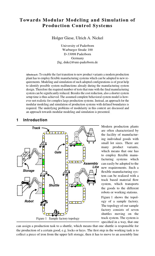
Towards Modular Modeling and Simulation of Production Control SystemsHolger Giese, Ulrich A. NickelUniversity of PaderbornWarburger Straße 100D-33098 PaderbornGermany[hg, duke]@uni-paderborn.deAbstract:To enable the fast transition to new product variants a modern productionplant has to employ flexible manufacturing systems which can be adopted to new re-quirements. Modeling and simulation of such adopted configurations is of great helpto identify possible system malfunctions already during the manufacturing systemdesign. Therefore the required number of tests that runs with the final manufacturingsystem can be significantly reduced. Besides the cost reduction, also a shorter systemsetup time is thus achieved. The assumed complete behavioral system model is how-ever not realistic for complex large production systems. Instead, an approach for themodular modeling and simulation of production systems with defined boundaries isrequired. The underlying problems of modularity in this context are discussed andan approach towards modular modeling and simulation is presented.1IntroductionModern production plants Array are often characterized bythe facility of manufactur-ing individual goods withsmall lot sizes. There aremany product variants,which means that one hasto employ flexible manu-facturing systems whichcan easily be adopted to thenew requirements. Such aflexible manufacturing sys-tem can be realized with atrack based material flowsystem, which transportsthe goods to the differentrobots or working stations.Figure1 shows the topol-ogy of a sample factory.The topology of our samplefactory consists of sevenshuttles moving on thetrack system. The system isspecified in a way, that one can assign a production task to a shuttle, which means that one shuttle is responsible for the production of a certain good, e.g. locks or keys. The first step in the working task is tocollect a piece of iron from the upper left storage, then it has to move to an assembly linewhich is able to perform the required manufacturing step. At each transfer gate the shuttle has to decide where it wants to go according to the choice of the assembly line and the shortest path to get there. Once the shuttle has reached an assembly line, the piece of iron is taken from the shuttle, the assigned good is produced, and put back on the shuttle again.After that, the shuttle moves to the storage where the good is stored. Finally, the shuttle reaches the end of its working task and starts again from the beginning. The shuttle will perform this task until it gets a new assignment. [KNNZ00] describes in detail the specifi-cation of this sample factory and introduces different modeling techniques. These model-ing techniques are supported by the Fujaba 1 environment.Assume, that a new kind of good shall be produced. If one has to change the topology of the material flow system, e.g., often big parts of the control software have to be specified anew. This causes long down times due to extensive tests. Thus, in [NN01] we described an approach of how we can simulate the modified specification of the control software,beforehand. Due to the fact that Fujaba is able to generate executable Java code, our sim-ulation environment can observe the running code by using the Java reflection library. Pro-duction sequences can be visualized and analysed. The simulation is based on a simulation kernel, which serves as a model for the physical components of the production system.This simulation approachimplies, that we have a com-plete specification of both, theproduction control software,and the physical elements of themanufacturing plant. Imagine,that we just change the set-upfor the assembly line or theCNC-code of a robot. In a largeproduction system this happensfrequently. In the worst case,this would cause an extensiveadaption of some parts of thespecification. But, for materialflow purposes, the exact behav-iour of an assembly line is notrelevant. It is only important,that a shuttle can communicatewith the assembly line via a par-ticular protocol or how long theassembly line takes to perform the next production step. Other details as specified in the statechart of the AssemblyLine class in Figure 2 are however not relevant. We therefore have to avoid such overspecification and apply the traditional software engineering princi-ples of separation and modularization.The description of external phenomena like the AssemblyLine in form of a class is however a problematic solution. Traditional class-based object-oriented design does not emphasize separation and thus more rigorous separation by means of interfaces is required when direct class dependencies should be avoided. This implicit treatment does however not support the independent deployment and composition of parts. The component paradigm[Szy98] therefore demands to consider the contractual relations more explicit to support the systematic exchange of parts. Instead of direct class relations explicit contracts have to be used. The concept of evaluation by simulation does also not scale up to complex sys-tems, because the cognitive capacity of a human to keep track with the simulation results Figure 2 Statechart of AssemblyLinevisualized by the tool is rather limited in practice. Thus, an overall system simulation is not directly applicable for evaluation of complex systems. A compositional component-based approach is therefore needed which supports the original scenario of simulation-based early design evolution.The rest of the paper is organized as follows. In Section 2 the modularization and separa-tion in form of component concepts and UML-RT are considered. Some inherent restric-tions for contract-based specifications w.r.t. component behaviour and simulation are dis-cussed. In Section 3 an adjusted notion for contracts and components that supports the required compositional component notion and partial model simulation is presented. The resulting evaluation scenario in form of simulations is described in Section 4. In Section 5related Work is discussed and the paper is concluded.2Modularization and SeparationIn the literature, a number of different notions for contracts have been proposed which can be classified by the following hierarchy [BJW99]: syntactical interface, behaviour, syn-chronization and quality of service. While contracts in form of syntactical interfaces are supported by all typed programming languages and middleware platforms, full behav-ioural contracts, e.g. in form of pre- and post-conditions, are rarely used in practice. Syn-chronization contracts can describe the non uniform service availability, while also request scheduling solutions such as specific reader/writer policies are possible. Quality of service contracts further allow to describe the contract behaviour w.r.t. time and throughput char-acteristics, but their platform dependent nature renders their consideration during design and simulation a complex task. For the real-time and embedded system domain ROOM[SGW94] and its successor UML-RT [SR98] propose a component concept (capsules)with explicit connections (ports) which support the synchronization contract concepts. A very general notion of a protocol is employed to specify general multi-party interactions which includes binary protocols which are by far the most common ones. The ROOM port concept permits to restrict the possible interaction via a specific connection to a certain set of signals specified by a given protocol role in form of a statechart.When, instead of implicit abstract classes such asAssemblyLine, a contract CAssembly as pre-sented in Figure 3 with a protocol is used to describe the component boundary, a slightly differ-ent situation arise. The implicit description of the component environment as described in Section 1builds a specific test frame whose initial configura-tion realizes one suitable test scenario, e.g., the ini-tial number of stored tasks in the Task class restricts the observed test cases. Instead of theexplicit construction of one specific test framebuilt by classes representing the external compo-nents, the knowledge given by the far more generalcontracts for specific component connectionsshould be used to support the modular simulationof the system.However, a more restricted notion of contract is required. Therefore, a contract in the pre-sented modular design approach is a boundary object, like a UML-RT port rather than a pure abstract concept such as an interface. We further restrict these rather general notion of protocols and protocol roles to the binary case to exclude the complexity of multi-party interactions and their sheduling [JS96]. We can use the visual short-cut of a black box for a main protocol role and a white one for its counterpart. The explicit handling of the main protocol role and its complementary role is also simplified using a single <<contract>> ste-Figure 3 Contract of AssemblyLinereotype to specify exactly one main protocol for the providing side and derive the usage protocol of the client side, implicitly.In Figure 3 for the Assem-blyLine class an explicit contract CAssembly has been presented.The whole subsystem of the fac-tory example of Figure 1 can be redesigned in this manneremploying the component andcontract concepts. In Figure 4 a Factory subsystem developed inthis manner is presented. The description employs the UML-RT concepts to denote the provided and used boundary contracts of the factory subsystem in form of ports. In the given factory example the task processing provided via the CTask contract is realized using the CSource ,CAssembly, CTarget and CPlanRepository contract.The simulation of a given component realization by means of a set of UML statecharts can be improved using the contract protocols of its provided and used contracts. In a first step,the contract protocols can be used to build the most general possible component environ-ment by generating arbitrary request sequences as guaranteed via the provided contracts and assuming the behaviour guaranteed by the used contracts. A simulation can, however,cover only the possible system behaviour but fail for lifeness aspects. When classes repre-sent the component border in an implicit manner, the model simulation can assume progress for each single statechart, because it describes a realization which is executed. In contrast, to assume progress for a given set of provided and used contracts will also result in the obligation of connected components to serve them in an independent manner. In practice, however, provided and used behaviour do often depend on each other and there-fore progress and lifeness properties can not be handled for each contract in isolation.1The described contract concept as short-cut of the port and capsule extension provided by UML-RT thus permits to evaluate whether the component connections are used and pro-vided in a protocol conform manner. However, the proposed protocols and contracts are not sufficient to achieve the intended modular form of designs which supports validation by simulation. The protocol restrictions do not address lifeness properties and therefore fail to describe the component environment as required.3The ApproachTo overcome the in Section 2 presented limitations for contract protocols, we extend the used notion of statecharts and further distinguish progress and quiescent transitions[Rei98] denoted by usual and dashed arcs, respectively. We further demand that progress is guaranteed by the contract provider and all possible provider events are never blocked by the clients. Therefore, a secure usage will only result in a situation where clients will wait for the answers or guaranteed state changes of the provider, whereas the provider cannever be blocked by a client.served in a fair manner. If no fairness is assumed, a set of client requests will only exclude the blocking of one of its members, when the direct or indirect synchronization of the clients itself exclude that one client can rule out any other one. Therefore, to implement fairness in an explicit manner based on a set of unfair operating compo-nents is a rather hopeless undertaking. The single components should instead guarantee to process the different client request in a fair manner, e.g., using a fair request queue. It has to be noticed, that for the simulation with implicit environments the same problem exists .in:CTThe progress guarantee for provided contracts results in arbitrary protocol conform usage by the test environment. For the used contracts the guaranteed progress is employed during simulation and therefore only relevant cases of permanent blocking are observed. The boundary contracts CTask, CSource ,CT arget, CAssembly and CPlanRepository con-tract have to be combined with the executable model of the factory example to obtain the intended test scenario. A task request may occur and the appropriate processing by the shuttles is initiated. The used contracts CSource ,CT arget, CAssembly and CPlanRe-pository are requested as specified exploiting the progress property. The progress of a con-tract, however, cannot always be guaranteed by the realizing component independently of the component environment and the interplay with other components. The described test environment construction is therefore only valid in a strictly layered architecture. If more general forms of architectures are considered the relation between provided and used con-tracts of components cannot be ignored. In contrast to safety properties it is problematic to ensure lifeness properties such as progress for arbitrary connected components. Therefore,commonly the whole component covering behaviour descriptions in form of processes such as formalized by CSP [Hoa85], CCS [Mil89] or LOTOS [ISO89] have to be consid-ered. An overwhelming variety of preorders and congruences for process refinement and abstraction have been proposed for these process algebraic approaches to address whether a given external component specification is realized correctly. The proposed relations,however, have to ensure substitutability [LW93] w.r.t. any possible process environment and therefore often result in very tight specification realization relations. The relations enforce that the specification has to reveal too many details of a realization, e.g., the com-plete buffering effects, and therefore do not provide the necessary degree of separation.In a layered architecture with acyclic module usage relations, in contrast, a separate treat-ment of lifeness properties becomes feasible [LS94] by exploiting the acyclic nature of dependencies. We generalize this idea to support separation for progress properties even for non-layered structures employing explicit contract dependencies for a given set of pro-vided and used contracts. In [Gie00] even the combination with explicit partial external specifications covering a subset of the used or provided contracts of a component are pre-sented. To specify such complex dependencies between multiple provided and used con-tracts so-called complex contracts describing the explicit behaviour and synchronization can be employed. By including the traditional case of a complete external specification in form of a specification process the approach supports a whole spectrum of possible com-ponent descriptions varying w.r.t. the degree of abstraction and embedding restrictions. For the factory example we consider only the simplest case to build the needed overall compo-nent behaviour based on explicit specified contract dependencies.In Figure 5 the dependencies between the provided CT ask contract of the Factory compo-nent and the used contracts arespecified. While the cooperation of the CSource ,CT arget andCAssembly contracts are defi-nitely needed for the task pro-cessing the CPlanRepositorycontract is only used in a spo-radic manner to update thelocally stored machine control programs. Therefore, no such explicit dependency has to be declared. If a used contract is required to realize the behaviour of a provided contract, we have to declare a dependency between them to make this regress explicit. We further have to restrict that for the composition of components the concatenated dependency relations remains acyclic. The specified dependencies therefore guide the possible component com-Figure 5 The Factory component and its dependenciesin:CTposition by demanding that a component embedding never results in a cyclic progress dependency[Gie00].4Modular SimulationUsing this additional information a suitable test environment can be constructed. While the provided and used contract protocols are combined as described before, the progress of provided and used contracts of the test environment is non-deterministically controlled as specified by the contract dependency relation. When the test environment in a specific state is waiting for progress at the CTask contract, it has to provide progress for the CSource, CAssembly and CTarget contracts. The CPlanRepository contract, in contrast, needs not to be served in this stateBesides the component internal dependencies between provided and used contracts the overall component behaviour of a factory is of interest. We propose to use a set of UML sequence diagrams to specify the necessary component behaviour. For the realization of the component must then hold that when a prefix of one such specified trace can be detected the overall partial trace has to be conform with one of the given sequence dia-grams.In Figure6 the expected property Array for a single do request to a factoryis specified. Using a sequence dia-gram and the scenario based tech-niques permit to consider thisrequirement in separation. The fac-tory realization will process multi-ple do request in parallel, but for each single request the presented sequence diagram can be used as necessary behavioural property. A simulation scenario should therefore take track of the initiated do requests and whether the specified related deliver requests have occurred.5Related WorkThere is a vast literature on the subject of simulation, e.g. [Zel92] and [Lie95]. Due to the high complexity of production control systems, the analysis of such systems is hard to manage. Thus, simulation systems are used for the analysis purposes [Rei72]. Simulation environments like Simple++ [Tec98] support the design an simulation of a manufacturing process. However, the specification of the control software is not based on an integrated object oriented modelling approach which is formally defined [KNNZ00]. Synchronization and contracts have been identified as essential aspects that must be com-bined to support abstraction and separation. Traditionally, architectural aspects are often neglected in object-oriented system design. Several proposals for the software architecture of distributed systems exist. The analysis of distributed message passing systems is inte-grated into the architecture description language Darwin [MDEK95], but its emphasis is to establish a certain system configuration, while the component behavior and connector typing are excluded. The Rapide approach [LAK+95] in contrast concentrates upon con-currency issues and provides tool support for simulation and successive analysis of the resulting runs, but the techniques offered to construct the component behavior are at the level of programming languages and thus do not provide the necessary more abstract behavioral view. A suitable idea is to consider connections (connectors) to be a kind of first class elements of an architecture. The Wright language [AG97] supports such a formal specification and analysis of connections, including also a conformance notion that may be used as requisite for subtyping.Regular types [Nie93] proposes to add a finite statemachine to an object interface is another proposal. These approaches however omit thequestion of how to relate the different protocols to a consistent component behavior and how to address lifeness of the overall system behavior.In contrast, the presented approach provides the notion of a behavioral contract and the presented depend relation to exclude synchronization problems without specifying con-crete behavioral properties, directly. The contract behavior does indeed represent the designed life-cycle or protocol provided by a component to the client and thus is part of its essential semantics which is necessary to understand and use it. Therefore, the contract protocols are a natural view during system design and when composing components. The depend relation, which is related to the component implementation, is in contrast to a com-plete external process-based specification rather abstract. The implied restriction for com-ponent composition to contain no cyclic dependencies is further an easily applicable rule. The analysis of software architectures for distributed systems based on state machine views and approaches for compositional analysis have been presented in [GKC99]. How-ever, the approach is restricted to hierarchical systems. The presented notion for compo-nent types in contrast supports more general scenarios for component composition. It ensures that basic lifeness anomalies such as deadlocks or starvation can be excluded for the composition of components when the simple rule of acyclic dependencies is fulfilled 6Conclusion and Future WorkIn this position paper a concept to enable partial model evaluation in form of simulation has been presented. It has been presented which extensions to traditional contract-based component separation are required to end up in a useful and appropriate component envi-ronment notion which supports partial simulation. The proposed technique to describe the component behaviour and component environment does further provide the necessary restrictions to exclude unexpected component embeddings which invalidate the assumed dependencies for the provided and used contracts of a component. We plan to further extend the presented ideas to also address quality of service contracts in a modular manner to further improve the support for the design and evaluation of complex real-time systems. References[AG97]R. Allen and D. Garlan. A Formal Basis for Architectural Connections.ACM Transactions on Software Engineering and Methodology,6(3):213-249, July 1997.[BJW99]Antoine Beugnard, Jean-Marc Jezequel, and Damien Watkins. Making Components Contract Aware. IEEE Computer, 32(7):38-45, July 1999. [Gie00]Holger Giese. Contract-based Component System Design. In Jr. RalphH. Sprague, editor, HICSS-33, Maui, Hawaii, USA. IEEE Press, January2000.[GKC99] D. Giannakopoulou, J. Kramer, and S.C. Cheung. Analysing the Behaviour of Distributed Systems using Tracta. Journal of AutomatedSoftware Engineering, special issue on Automated Analysis of Software,6(1):7-35, January 1999.[Hoa85] C. A. R. Hoare. Communicating Sequential Processes. Series in Computer Science. Prentice-Hall International, 1985.[ISO89]ISO, JTC 1/SC 7, Geneve. LOTOS _ A Formal Description Technique Based on the Temporal Ordering of Observational Behaviour, September1989. ISO/IS 8807.[JS96]Yuh-Jzer Joung and Scott A. Smolka. A comprehensive study of the complexity of multiparty interaction. Journal of the ACM, 43(1):75-115,January 1996.[KNNZ00]H. Köhler, U. A. Nickel, J. Niere, A. Zündorf: Integrating UML Diagrams for Production Control Systems; ICSE 2000, June 4-11th, Limerick, Ireland,ACM press, pp. 241-251(2000)[LS94]S. S. Lam and A. U. Shankar. A theory of interfaces and modules i-Composition theorem. IEEE Transactions on Software Engineering,20(1):336-355, January 1994.[LAK+ 95] D. C. Luckham, L. M. Augustin, J. J. Kenny, J. Vera, D. Bryan, and W.Mann. Specification and analysis of system architecture using Rapide.IEEE Transactions on Software Engineering, 21(4):336-355, April 1995. [Lie95] F.Liebl. Simulation. A problem oriented introduction (in german).Oldenbourg, Munich, 2nd edition, 1995.[LW93]Barbara Liskov and Jeannette M. Wing. A New Definition of the Subtype Relation. In Oscar M. Nierstrasz, editor, ECOOP '93, LNCS 707,pages 118-141, July 1993.[MDEK95]J. Magee, N. Dulay, S. Eisenbach, and J. Kramer. Specifying distributed software architectures. In Fifth European Software EngineeringConference (ESEC’95), volume 989 of Lecture Notes in ComputerScience, pages 137-153. Springer Verlag, September 1995.[Mil89]R. Milner. Communication and Concurrency. Prentice-Hall International, 1989.[Nie93]Oscar Nierstrasz. Regular Types for active Objects. In Proceedings OOPSLA’93, volume 28 of ACM SIGPLAN Notices, pages 1-15,October 1993.[NN01]U. A. Nickel, J. Niere. Modeling and Simulation of a Material Flow System.In Proc. of Workshop 'Modellierung', Bad Lippspringe, Germany, 2001. [Rei72] A.Reinhardt. Simulation eines Fertigungsprozesses in GASP. Großmann, 1972.[Rei98]Wolfgang Reisig. Elements of Distributed Algorithms, Modeling and Analysis with Petri Nets. Springer Verlag, 1998.[SGW94]Bran Selic, Garth Gullekson, and Paul Ward. Real-Time Object-Oriented Modeling. John Wiley & Sons, Inc., 1994.[SR98]Bran Selic and Jim Rumbaugh. Using UML for Modeling Complex Real-Time Systems. Techreport, ObjectTime Limited, 1998.[Szy98]Clemens Szyperski. Component Software, Beyond Object-Oriented Programming. Addison-Wesley, 1998.[Tec98]Technomatix. Technomatix: Reference Manual, SIMPLE++ 5.0, Handbuch zur Simulationssoftware, 1998.[Zel92]M.Zell, editor. Simulation based manufacturing control. Oldenbourg, Munich, 1992.。

simulation parameters and results -回复Simulation Parameters and ResultsIntroduction:Simulation is the process of creating an artificial model of areal-world system to understand its behavior and predict its outcomes. It has become an essential tool in various fields such as engineering, economics, and social sciences. In this article, we will explore the different parameters involved in simulation and discuss how they affect the results obtained.Step 1: Defining the ProblemThe first step in simulation is to define the problem or thereal-world system that needs to be modeled. This involves understanding the objectives and constraints of the system. For example, in a manufacturing process, the objective could be to optimize production while minimizing costs.Step 2: Identifying the VariablesOnce the problem is defined, the next step is to identify the variables that affect the behavior of the system. These variables can be classified into two categories: input variables and output variables. Input variables are the ones that can be controlled or manipulated, such as production rate, machine speed, or inventory levels. Output variables are the ones that are influenced by the input variables, such as production output, average waiting time, or customer satisfaction.Step 3: Determining the ModelAfter identifying the variables, the next step is to determine the model that represents the system. The model can be a mathematical equation, a set of equations, or a computer program. The model should capture the relationships between the variables and enable the simulation of the system's behavior.Step 4: Specifying the AssumptionsIn simulation, assumptions play a crucial role in simplifying the model and making it manageable. Assumptions are necessary because it is not always possible to consider all the factors thatinfluence the system's behavior. Assumptions can be related to the behavior of the variables, the distribution patterns, or the constraints of the system. It is important to clearly state the assumptions made to avoid any confusion in the interpretation of the results.Step 5: Selecting the Simulation TechniqueThere are different simulation techniques available, depending on the nature of the system being modeled. Some common simulation techniques include discrete-event simulation, system dynamics, and agent-based simulation. The selection of the simulation technique depends on factors such as the complexity of the system, the availability of data, and the objectives of the simulation.Step 6: Setting the ParametersOnce the simulation technique is selected, it is essential to set the parameters that define the system's behavior. These parameters can include the initial conditions, the rules governing the system's dynamics, and the decision-making process. For example, in a supply chain simulation, the parameters could be the lead time,order quantities, and reorder points.Step 7: Running the SimulationAfter setting the parameters, the simulation can be run using appropriate software or programming tools. The simulation generates a sequence of values for the output variables based on the specified values of the input variables. The simulation runs for a specific duration or until a predefined condition is met.Step 8: Analyzing the ResultsOnce the simulation is completed, the results need to be analyzed to gain insights into the system's behavior. The analysis can include statistical measures such as mean, standard deviation, or percentiles. It can also involve visualization techniques such as histograms or line graphs to understand the patterns and trends in the data obtained.Step 9: Validating the ModelValidation is the process of comparing the simulation results withreal-world data or observations to ensure the accuracy of the model. If the simulation results closely match the observed behavior, it can be concluded that the model is valid and can be used to make predictions or test scenarios.Step 10: Sensitivity Analysis and Scenario TestingSensitivity analysis involves studying how changes in the input variables affect the output variables. It helps in understanding the critical factors that influence the system's behavior. Scenario testing involves simulating different scenarios to explore the system's response under various conditions. Both sensitivity analysis and scenario testing help in making informed decisions and improving the system's performance.Conclusion:Simulation is a powerful tool for understanding complex systems and making informed decisions. By carefully defining the problem, identifying variables, determining the model, and setting the parameters, accurate results can be obtained. However, it isimportant to interpret the results with caution and validate the model against real-world data. Simulation provides a valuable platform for experimentation and optimization, ultimately leading to better system design and performance.。
仿真模拟算力测算案例### Simulation and Computing Power Estimation.1. Introduction.Simulation is a powerful tool that can be used to model and analyze complex systems. It can be used to predict the behavior of a system under different conditions, and to identify potential problems. However, simulation can also be computationally expensive, especially for large and complex systems.The amount of computing power required for a simulation depends on a number of factors, including:The size of the system being simulated.The complexity of the system being simulated.The level of detail required in the simulation.The desired accuracy of the simulation.2. Estimating Computing Power Requirements.There are a number of different methods that can be used to estimate the computing power requirements for a simulation. One common method is to use a benchmark. A benchmark is a set of standard tests that are used to measure the performance of a computer system. By running a benchmark on a computer system, you can get an idea of how well the system will perform on a particular simulation.Another method for estimating computing power requirements is to use a simulation profiler. A simulation profiler is a tool that can be used to measure the performance of a simulation. By profiling a simulation, you can identify the parts of the simulation that are most computationally expensive. This information can then be used to optimize the simulation and reduce the computing power requirements.3. Reducing Computing Power Requirements.There are a number of different ways to reduce the computing power requirements for a simulation. One way isto use a simpler model. A simpler model will typically require less computing power than a more complex model. Another way to reduce computing power requirements is touse a less accurate simulation. A less accurate simulation will typically require less computing power than a more accurate simulation.Finally, you can also reduce computing power requirements by using a more efficient simulation algorithm.A more efficient simulation algorithm will typicallyrequire less computing power than a less efficientsimulation algorithm.4. Conclusion.Simulation is a powerful tool that can be used to model and analyze complex systems. However, simulation can alsobe computationally expensive, especially for large andcomplex systems. By understanding the factors that affect computing power requirements, you can make informed decisions about how to optimize your simulations and reduce the computing power requirements.### 仿真模拟算力测算。
simulation modeling and analysis(最新版)目录1.模拟建模和分析的概述2.模拟建模和分析的应用领域3.模拟建模和分析的步骤4.模拟建模和分析的挑战与未来发展正文模拟建模和分析(Simulation Modeling and Analysis)是一种通过构建数学模型来模拟现实世界中的系统和过程,以便进行分析和求解的方法。
在各个领域中,模拟建模和分析都发挥着重要作用,如工程、科学、经济学、社会学等。
本文将介绍模拟建模和分析的概述、应用领域、步骤以及挑战与未来发展。
一、模拟建模和分析的概述模拟建模和分析是一种强大的技术,可以对复杂的现实世界问题进行建模,并在计算机上运行这些模型以进行分析。
这种方法可以帮助我们更好地理解系统的行为,进行决策分析,以及预测未来情况。
二、模拟建模和分析的应用领域1.工程领域:在工程领域,模拟建模和分析被广泛应用于设计、制造和优化各种产品和系统,如汽车、飞机、建筑等。
2.科学领域:在科学领域,模拟建模和分析被用于研究复杂的自然现象,如天气、生态系统、宇宙等。
3.经济学领域:在经济学领域,模拟建模和分析可以帮助分析经济政策、预测市场行为等。
4.社会学领域:在社会学领域,模拟建模和分析可以用于研究社会现象,如人口增长、城市规划等。
三、模拟建模和分析的步骤模拟建模和分析通常包括以下几个步骤:1.问题定义:明确需要解决的问题,确定问题的边界和目标。
2.系统建模:根据问题定义,构建一个数学模型来描述系统的结构和行为。
3.模型参数化:为模型分配参数值,这些参数值通常基于历史数据或专家意见。
4.模型校准:通过与实际数据进行比较,调整模型参数以提高模型的准确性。
5.模型分析:使用模型进行分析,例如求解最优解、预测未来情况等。
6.结果解释:根据分析结果,对问题进行解答并提出建议。
四、模拟建模和分析的挑战与未来发展尽管模拟建模和分析在各个领域取得了显著成果,但仍面临着一些挑战,如模型的准确性、参数的选择等。
simulation modelling practiceSimulation modelling is a crucial tool in the field of science and engineering. It allows us to investigate complex systems and predict their behaviour in response to various inputs and conditions. This article will guide you through the process of simulation modelling, from its basicprinciples to practical applications.1. Introduction to Simulation ModellingSimulation modelling is the process of representing real-world systems using mathematical models. These models allow us to investigate systems that are too complex or expensiveto be fully studied using traditional methods. Simulation models are created using mathematical equations, functions, and algorithms that represent the interactions and relationships between the system's components.2. Building a Basic Simulation ModelTo begin, you will need to identify the key elements that make up your system and define their interactions. Next, you will need to create mathematical equations that represent these interactions. These equations should be as simple as possible while still capturing the essential aspects of the system's behaviour.Once you have your equations, you can use simulation software to create a model. Popular simulation softwareincludes MATLAB, Simulink, and Arena. These software packages allow you to input your equations and see how the system will respond to different inputs and conditions.3. Choosing a Simulation Software PackageWhen choosing a simulation software package, consider your specific needs and resources. Each package has its own strengths and limitations, so it's important to select one that best fits your project. Some packages are more suitable for simulating large-scale systems, while others may bebetter for quickly prototyping small-scale systems.4. Practical Applications of Simulation ModellingSimulation modelling is used in a wide range of fields, including engineering, finance, healthcare, and more. Here are some practical applications:* Engineering: Simulation modelling is commonly used in the automotive, aerospace, and manufacturing industries to design and test systems such as engines, vehicles, and manufacturing processes.* Finance: Simulation modelling is used by financial institutions to assess the impact of market conditions on investment portfolios and interest rates.* Healthcare: Simulation modelling is used to plan and manage healthcare resources, predict disease trends, and evaluate the effectiveness of treatment methods.* Education: Simulation modelling is an excellent toolfor teaching students about complex systems and how they interact with each other. It helps students develop critical thinking skills and problem-solving techniques.5. Case Studies and ExamplesTo illustrate the practical use of simulation modelling, we will take a look at two case studies: an aircraft engine simulation and a healthcare resource management simulation.Aircraft Engine Simulation: In this scenario, a simulation model is used to assess the performance ofdifferent engine designs under various flight conditions. The model helps engineers identify design flaws and improve efficiency.Healthcare Resource Management Simulation: This simulation model helps healthcare providers plan their resources based on anticipated patient demand. The model can also be used to evaluate different treatment methods and identify optimal resource allocation strategies.6. ConclusionSimulation modelling is a powerful tool that allows us to investigate complex systems and make informed decisions about how to best manage them. By following these steps, you can create your own simulation models and apply them to real-world problems. Remember, it's always important to keep anopen mind and be willing to adapt your approach based on the specific needs of your project.。
Modeling and Simulation of Pathloss and Fading for Air-Ground Link of HAPswithin a Network SimulatorYi Zheng, Yuwen Wang, Fanji MengSchool of Aeronautics and AstronauticsUniversity of Electronic Science and Technology of ChinaChengdu, ChinaE-mail: zhy_uestc@Abstract—Development in Near Space Vehicle communicationhas increased the need for simu ation to test and ana yzeprotoco s for this emerging techno ogy. Network simu atorslack a realistic near space path loss and fading module whichwoul d al low having accurate simulation. To explore andsimul ate accurately the influence of rain, cloud, gaseousabsorption and mul tipath fading on the air-ground l ink, the mathematical and simulation models for the rain attenuation, cl oud attenuation, gaseous absorption attenuation and Ricean fading were implemented. Moreover, modeling and simulation were done within Qual Net. Simul ation resul ts quantitativel y show the effects of rain attenuation, cloud attenuation, gaseous absorption attenuation and Ricean fading on the performance of packet del ivery rate of the High Al titude Pl atform station (HAPs) air-ground l ink. Thus, simul ation of the air-ground l ink becomes more accurate and reasonabl e. Simul taneousl y, the used simul ation pl atform is al so improved by integrating new models.Keywords-High Altitude Platform station; air-ground link; path loss; Ricean fading; QualNet;I.I NTRODUCTIONRecent years have witnessed a tremendous growth in research and application of HAPs communication networks. The great advances have been spurring more and more interest and excitement. However, due to utilization of wireless communications, the performance of air-ground link is inevitably influenced by the intrinsic effects of wireless propagation, such as rain, cloud, gaseous absorption and multipath fading. These effects are dynamic, random and relevant to the environment, thus it is a challenge to accurately explore and simulate the impact on the performance of air-ground link. Some network level simulation experiments seldom consider these effects in radio propagation, which lead to over-optimistic simulation results. Thus, there is a need to accurately model and simulate the four factors above so as to explore their impact on the performance of the air-ground link.The research on modeling and simulation of path loss and fading of HAPs and near space vehicle networks has been done in many literatures. [1] researched the small-scale fading model of HAPs communication; [2] studied the multiple antenna channel model in detail; [3] summed up and analyzed the channel model, which was applied in the HAPs communication. This paper also revealed the advantages and disadvantages of each model; Ratish J. Punnoose et al.[4] implemented the simulation of Ricean fading within a packet simulator; [5] evaluated the performance of variable step closed loop power control algorithm for CDMA communication employing HAPs. A.I. Alshbatat, et al.[6] designed a new Medium Access Control (MAC) scheme that adapted its parameters based on the channel bit error rate which was indeed affected by the new antenna system and aircraft attitude and developed the Optimized Link State Routing Protocol (OLSR) so that the decision for selecting the route will be based on a local profile that holds the gathered information from the first three layers.The above references show the research advances in modeling and simulation of HAPs communication network and channel model of HAPs communication. However, there are few results about the impact of rain, cloud, gaseous absorption and multipath fading on the performance of air-ground link of HAPs. Also, there are few results about the propagation models, which are applied to the network-level simulation of communication system. So far, there are some commonly used network simulators, such as OPNET, QualNet and NS-2, while there are only some simple propagation models, for example, free-space loss model. These simple models can’t be directly used to simulate the propagation model for air-ground link of HAPs.To address the aforementioned issue, this paper studies the influence of rain, cloud, gaseous absorption and multipath fading on the air-ground link by theoretical analysis, modeling and simulation. A comprehensive loss model and Ricean fading model, which can be applied to near space environment, were implemented within QualNet.The rest of this paper is organized as follows. In Section II, the theoretical analysis and mathematical modeling of the rain attenuation, cloud attenuation and gaseous absorption attenuation are conducted. Section III provides the modeling of Ricean fading. In Section IV, some simulation results are demonstrated to confirm the effects of atmospheric effects and small-scale fading for air-ground link of HAPs. Finally, conclusions are presented in Section V.II.M ODELING OF P ATHLOSS M ODELPath loss model is also known as large-scale fading model. To research the path loss model for air-ground link of HAPs, the main factors to be considered include free-space loss, rain attenuation, cloud attenuation, gaseous absorption attenuation. Currently, there are several models for the mentioned above. The ITU-R series models are the most common models among these ones in engineering. Therefore,2013 International Conference on Cyber-Enabled Distributed Computing and Knowledge Discoverythis paper focuses on the series models in the QualNet simulator.A. Rain AttenuationElectromagnetic wave is absorbed and scattered by raindrops, eventually leading to attenuation, which is called rain attenuation. This kind of attenuation is mainly related with raindrops geometry, rainfall intensity, rain zone, the signal frequency and polarization. When the frequency is more than 10GHz, rain attenuation is the major factor effecting the quality of communication link. At present, the rain attenuation has been the subject of intensive study. A number of models are established and mainly include the ITU-R model [7-10], SAM model [11], DAH model [12], etc.The ITU-R rain attenuation model calculates thepredicted attenuation exceeded for 0.01% of an average year(dB):0.01R E A r L = (1)Where, R r is the specific rain attenuation in (dB/km), E L is the effective path length (km). For other percentages, p of an average year, which in the range 0.001% to 10%, the attenuation can be estimated by the following extrapolation equation: 0.01[0.6550.033ln()0.045ln()(1)sin ]0.01()()0.01p A p R pA p A βθ−+−−−= (2)Where, if p ı1%, then β=0; if p<1%, β can be calculated by (3).0||36=0.005(||36)||36250.005||36+1.8 4.25sin ||3625and and ϕβϕϕθϕθϕθ≥°−−<°≥°−−−<°<°°®°¯䯴䯵 (3) B. Cloud AttenuationCloud usually consists of small droplets. The diameter of droplet is generally less than 0.01cm. Its radio attenuation is mainly due to absorption and scattering effect is negligible. The cloud attenuation is related to temperature and liquid water content in the cloud along the propagation path.To obtain the attenuation due to clouds for a given probability, the statistics of the total columnar content of liquid water L (kg/m 2) or, equivalently, mm of precipitable water for a given site must be known yielding [13]:905sin lC LK A for θθ=°≥≥° (4) Where ș is the elevation angle and l K is the specific attenuation coefficient. l K can be calculated as (5). 20.819''(1)l fK εη=+ (5)Where, f is the frequency (GHz).C. Gaseous Absorption AttenuationAttenuation entirely caused by absorption of atmospheric gases depends mainly on frequency, elevation angle, altitude above sea level and water vapour density (absolute humidity).When the frequency is below 10GHz, it may normally beneglected, however, when the frequency is above 10GHz, its importance on the attenuation increases with the increase of frequency, especially for low elevation angles.The ITU-R gaseous absorption attenuation model [14] calculates the predicted attenuation A G (dB) as (6).sin o o w wG h h A γγϕ+= (6)Where, o h is the equivalent height of dry air (km), w h is the equivalent height of water vapour (km). o γ is the specific attenuation of dry air (dB/km), w γ is the specific attenuation of water vapors (dB/km).D. Comprehensive Path Loss Model Comprehensive path loss (dB) represents the combined effect of rain, gas, clouds and scintillation. For systems operating at frequencies above about 18 GHz, especiallythose operating with low elevation angles, the effect of multiple sources of simultaneously occurring atmospheric attenuation must be considered [7]. A general method for calculating the total attenuation for a given probability, ()T A p, is given by (7).()()T G A p A p = (7)()G A p , ()R A p is the rain attenuation (dB), ()C A p is the cloud attenuation (dB), ()S A p is the scintillation attenuation (dB). Since this article ignores the scintillation attenuation, ()T A p can also be given by (8).()()()()T G R C A p A p A p A p =++ (8)Where, if p<1.0%, then ()()1%CCA p A =,()()1%G G A p A =. The comprehensive path loss of the air-ground link can be represented as (9).()()L F T A p A A p =+ (9) Where F A is the free-space loss (dB).III. M ODELING OF S MALL -SCALE F ADINGWhen the received signal, which is the sum of different replicas of the same transmitted signal arriving at the receiver following different paths, experiences constructive and destructive interference over short periods of time and/or short distances due to the relative motion of the receiver and transmitter, small-scale fading occurs. Small-scale fading typically contains two typical fading modes. When there is a dominant stationary signal component at present, such as a line-of-sight (LOS) propagation path, this fading model is called Ricean model. As the dominant signal in a Ricean model becomes weaker, the composite signal resembles a noise signal that has an envelope of a Rayleigh distribution, this fading model is called Rayleigh model.Since HAPs air-ground link communication scenario generally exists LOS propagation path and conforms to thecharacteristic of Ricean model, this article focuses on modeling and simulation of Ricean fading model.When the fading is Ricean fading, the moment i fading amplitude i r can be expressed as (10).i r =Where A is the amplitude of the LOS signal, i x and i y are Gaussian random variables, whose mean values are zero, and variance values are 20σ. Fading factor K is determined by (11).222AK σ=(11)Ricean fading distribution density function can be expressed as (12).()()()220222exp 0,0=200r r A Ar I A r p r r σσσ+−≥≥<§·§·°¨¸¨¸©¹®©¹°¯(12) By considering the distribution of non-coherent Ricean fading sequence generation method, the mean square value of Ricean distribution is ()221K σ+, 2σ denotes the variance of gaussian processes in (10). Thus, Equation (10) can be rewritten as the following equation:i r =(13)Where i x and i y are Gaussian random variables, whosemean values are zero and their variance are 20σ. Equation (13) gives the fading envelope distribution, and then, converts i rto _i r dB (dB), so (13) can also be expressed as (14). ()()22_10lg21i iix y r dB K +=+ (14)IV. A IR -G ROUND LINK S IMULATIONA. QualNet Channel Simulation System DesignFigure 1. Air-ground link channel simulation architectureRadio propagation impacts the quality of the communication links and networks. But now, in the study of communication networks, commonly used packet simulators have no detailed channel model and these simple models can’t achieve accurate modeling for air-ground link of HAPs. As a popular commercial network simulator, QualNet has standard network architecture and the characteristics of great extensibility. This paper uses this simulator as the simulation tool. By modifying the physical layer module, a more detailed propagation model for air-ground link than the existing ones is established. The simulation system is showed in Fig. 1.B. Simulation Scenario ConfigurationIn the simulation scenario, there is a fixed node acting as the ground station, which is located at (20ºN, 110ºE), and amobile node acting as the HAPs. The initial position of themobile node is above the fixed node, 200km/h flying to east, and its altitude is 30km. The HAPs sends four data packets per second to the ground station and the packet size is 512 bytes. The simulation period is 30 minutes. The bandwidth of the communication link is 2Mbps. Scenario diagram is showed in Fig. 2.Figure 2. Scenario configuration diagramSome parameters involved in the physical layer areshowed in Table I.TABLE I.T HE M AIN P ARAMETERS OF T HE P HYSICAL L AYERParameters Va l ueReceiver sensitivity (dBm) -102 Receiving antenna gain (dBi) 35Transmit power (W) 200 Transmitting antenna gain (dBi) 20Thermal noise (K) 290 Polarization mode Vertical polarizationThe regional climate information of the simulationscenario is showed in Table II.TABLE II.T HE R EGIONAL C LIMATE I NFORMATIONParameters Va lueRain rate exceeded for 0.01% of anaverage year (mm/h)95Cloud liquid water content exceededfor 0.1% of an average year (kg/m 2)4Median temperature (ć)25 Water vapor density (g/m 3) 7.5C. Simulation Result and Scenario Configuration1) Comprehensive path loss model simulationIn the simulation scenario, four simulation experiments were conducted. The communication frequency was set as 10GHz, 15GHz, 20GHz, 25GHz, respectively, while theother parameters remained unchanged. After these simulation experiments, a series of the rain attenuation exceeded for 0.01% of an average year, the cloud attenuation exceeded for 0.1% of an average year and the gaseous absorption attenuation under different distance were obtained in the experiments, respectively. These simulation results areshowed in the Fig. 3, Fig. 4 and Fig. 5, respectively.Figure 3.Rain attenuation exceeded for 0.01% of an average year Figure 4.Cloud attenuation exceeded for 0.1% of an average yearFigure 5. gaseous absorption attenuationFig. 3, Fig. 4 and Fig. 5 show that rain attenuation, cloud attenuation and gaseous absorption attenuation always increase with the increase of the frequency. It can also be observed that the main effect on the quality of air-ground communication link is rain attenuation among these three types of attenuation, while cloud attenuation and gaseous absorption attenuation have less effect on the communication link than rain attenuation. However, studying the latter two attenuation models is necessary to further improve the accuracy of modeling and simulation.In another experiments, the frequency was set as 20GHz, through simulation experiences, a series of rain attenuation exceeded for 0.01%, 0.1%, 1.0% and 10% of an average year under different distance can be obtained respectively. Experimental results are showed in Fig. 6. The figure reveals that rain attenuation exceeded for 0.01% and 0.1% of an average year are extremely large, while rain attenuation exceeded for 1.0% and 10% of an average year maintain at very low level. In most of the time, rain attenuation has little effect on the quality of air-ground communication link. However, the attenuation increases with the increase of rainfall, which will cause serious damage to normal communication of the link. In order to avoid link communication interruption, which is caused by rain, the link redundancy should be considered when designing air-ground link. Therefore, an accurate model of rain attenuation is essential for study and design the air-ground link of HAPs. The study of the rain attenuation has important practicalsignificance and application value.Figure 6. Rain attenuation exceeded for 0.01%, 0.1%, 1.0% and 10% ofan average yearFigure 7. Receiving signal power without fadingIn another experiment, the communication frequency was set as 20GHz and the percentage of the exceeded of an average year was 0.1%. Propagation model were set to free-space model and comprehensive loss model, respectively. Then, these two kinds of simulation scenarios were simulated and a series of receiving signal power under different distance were obtained. The results of the simulation are plotted in Fig. 7.It can be seen from Fig.7 that the atmospheric effect has significant impact on the quality of air-ground link when the exceeded of an average year reaches 0.1%.2)Small-scale fading model simulationSupposing the actual topography factor is ignored and LOS propagation path always exists between HAPs and the ground station in the simulation scenario, thus Ricean fading model can be applied to describe the scenario of the small-scale fading. The communication frequency was set as 20GHz in the experiments below.For specific scenario of HAPs air-ground communication link, the K factor is generally sets as 10dB. Thus, the amplitude changes due to small-scale fading were obtained. Fig. 8 shows the amplitude changes.Considering small-scale fading and comprehensive path loss impact on the communication link, a series of received signal power of the ground station were obtained during thesimulation, as showed in Fig. 9.Figure 8.Ricean fading amplitudeFigure 9. Receiving signal power with Ricean fading3)Comprehensive channel model simulationIn the simulation experiment, communication frequency was set as 20GHz, exceeded for percent of an average year was 0.1%. Free-space loss model, the comprehensive loss model without Ricean fading and the comprehensive loss model with Ricean fading acted as the propagation model, respectively. In each case, a series of packet delivery rate (PD R) were obtained and their performances of the HAPs air-ground communication link were compared. The PD Rare showed in Fig. 10.Figure 10. Packet delivery rate of different model In Fig. 10, the PD R is 99.98%, nearly 100%, when the propagation model is free-space loss model; the PD R is 94.027%, which is lower than the one of the free-space loss model, when the propagation model is the comprehensive loss model without Ricean fading; the PDR falls to 88.411%, which is the lowest among the three, when the propagation model is the comprehensive loss model with Ricean fading.V.C ONCLUTIONTo study the effect of rain, cloud, gaseous absorption and multipath fading on air-ground link of HAPs, this paper has implemented modeling and simulation of rain attenuation, cloud attenuation, gaseous absorption attenuation and Ricean fading within QualNet, which is a famous network simulator. Research results show that the four factors discussed above have significant impact on the performance of the air-ground link of HAPs, especially on the packet delivery rate. Simultaneously, it is verified that the research make the over-optimistic modeling and simulation more accurate and reasonable. In addition, the new models improve the function of the network simulator. Although the modeling and simulation work of this paper is based on QualNet, the ideas and methods can also be used for other network simulators, for example, OPNET and NS-2.A CKNOWLEDGMENTThe authors would like to express their great thanks to the anonymous reviewers due to valuable recommendations and comments that improve the paper.R EFERENCES[1] F. Dovis, R. Fantini, M. Mondin, and P. Savi. “Small-scale fading forhigh-altitude platform (HAP) propagation channels,” IEEE Journal onSelected Areasin Communications. Vol. 20, pp. 641-647, 2002.[2] E. Falletti, F. Sellone, C. Spillard, and D. Grace. “A Transmit andReceive Multi-Antenna Channel Model and Simulator for Communications from High Altitude Platforms.” International Journal of Wireless Information Networks. Vol. 13, pp. 59-75, January 2006.[3]Yong Yang, Ru Zong, Xinbo Gao, and Jie Cao. “Channel modelingfor High-Altitude platform: A review.” 2010 International Symposium on Intelligent Signal Processing and Communication Systems (ISPACS 2010), December, 2010.[4]R. J. Punnoose, P. V. Nikitin, and D. D. Stancil. “Efficient Simulationof Ricean Fading within a Packet Simulator.” Vehicular Technology Conference Fall 2000, pp. 764-767, September 2000.[5]Iskandar, A. Kurniawan, and M.E. Ernawan. “Performance ofVariable Step Closed Loop Power Control in CD MA High Altitude Platforms Communication Channel.” Vehicular Technology Conference Fall 2010 (VTC 2010-Fall), pp. 1-5, September 2010. [6] A. I. Alshbatat, Liang Dong. “Cross layer design for mobile Ad-HocUnmanned Aerial Vehicle communication networks.” 2010International Conference on Networking, Sensing and Control (ICNSC 2010), pp. 331-336, April 2010.[7]ITU-R, “Propagation data and prediction methods required for thedesign of Earth-space Telecommunication system.” Rec. ITU-R P.618-10, 2009.[8]ITU-R, “Specific attenuation model for rain for use in predictionmethods.” Rec. ITU-R P.838-3, 2005.[9]ITU-R, “Rain height model for prediction methods.” Rec. ITU-RP.839-3, 2001.[10]ITU-R, “Characteristics of precipitation for propagation modeling.”Rec. ITU-R P.837-6, 2012.[11]W.L. Stutzman, W.K. Dishman. “A simple model for the estimationof rain induced attenuation along earth space paths at millimeter wavelengths.” Radio Science. Vol. 17, pp. 1465-1476, 1982[12] A. Dissanayake, J. Allnut and F. Haidara. “A Prediction Model thatCombines Rain Attenuation and other Propagation Impairments Along Earth-Satellite Paths.” IEEE Transaction on Antennas and Propagation. Vol. 45, pp. 1546-1558, 1997[13]ITU-R, “Attenuation due to clouds and fog.” Rec. ITU-R P.840-5,2012[14]ITU-R, “Attenuation by atmospheric gases.” Rec. ITU-R P.676-9,2012。