rsp_pulmovista_500_making_ventilation_visible_9066478_en
- 格式:pdf
- 大小:226.60 KB
- 文档页数:8

EasyPep™ Mini MS Sample Prep Kit Catalog Numbers A40006Doc. Part No. 2162714 Pub. No. MAN0018079 Rev.B.0WARNING! Read the Safety Data Sheets (SDSs) and follow the handling instructions. Wear appropriate protective eyewear, clothing, and gloves. Safety Data Sheets (SDSs) are available from /support.Product descriptionThe Thermo Scientific™ EasyPep™ Mini MS Sample Prep Kit enables efficient and reproducible processing of cultured mammalian cells and tissues for proteomic mass spectrometry (MS) analysis. The kit contains pre-formulated buffers, MS-grade enzyme mix, peptide clean-up columns, and an optimized protocol to generate MS-compatible peptide samples in less than 3 hours. The kit is optimized to process protein samples from 10-100 µg with high yield of MS-ready peptides. Some key features of the kit that reduce total sample preparation time include: addition of Universal Nuclease to reduce viscosity from nucleic acids without the need for sonication, a rapid "one pot" reduction/alkylation solution for cysteine modification (carbamidomethylation, +57.02), and a trypsin/Lys-C protease mix for more complete digestion. In addition, the kit includes peptide clean-up columns and buffers to prepare detergent-free peptide samples for direct LC-MS analysis or further sample processing such as isobaric tag (e.g., TMT™ reagent) labeling, phosphopeptide enrichment or high pH reversed-phase fractionation.ContentsProcedure summaryAdditional information•Warm the Lysis Solution to room temperature before use. Store buffers and columns at 4°C.•Addition of phosphatase inhibitors to Lysis Solution (e.g., Halt™ Phosphatase Inhibitor Cocktail, Product No. 78420) is recommended before cell lysis for phosphopeptide enrichment and analysis.•Addition of protease inhibitor cocktails containing EDTA to Lysis Solution are NOT recommended as these reagents inhibit Universal Nuclease and Trypsin/Lys-C Protease Mix activity.•For long term storage (>3 months), store Universal Nuclease and Trypsin/Lys-C Protease Mix at -20°C.•After addition of Enzyme Reconstitution Solution, the Trypsin/Lys-C Protease Mix can be stored at 4°C for up to 1 month or -20°C for 1 year.•Use of peptide clean-up columns is required to remove contaminants and enzymes before LC-MS analysis.Materials required but not supplied•(Optional) Tissue homogenizer•Heat block or thermo mixer•Protein assay kit (e.g., Thermo Scientific™ Pierce™ BCA Protein Assay Kit, Cat. No. 23227)•Mass spectrometer with nano-flow liquid chromatography (LC) systemProcedureNote: Use 10-100 µg of protein per sample preparation. Rinse cultured cells or tissues 2-3 times with 1X PBS to remove cell culture media or excess blood, respectively. Resuspend proteins, cells or tissues in Lysis Solution without additional buffers.Extract protein, reduce, and alkylate1.For cultured cells, add 100 µL of Lysis Buffer and 1 µL of Universal Nuclease to a minimum of 1 × 10⁶ cells. Pipet up and down (with P200 tip)for 10-15 cycles until sample viscosity is reduced.Note: Centrifugation of cultured cell lysates is typically not required after aspiration using pipet.2.For tissue samples, add 100 µL of Lysis Solution (containing 1 µL Universal Nuclease) per 5 mg of tissue and disrupt with tissue homogenizeruntil sample is homogenized. Centrifuge tissue lysates at 16,000 × g for 10 minutes.3.For purified proteins, serum, and plasma samples, dilute samples directly in Lysis Solution to 0.1-1 mg/mL. Use 0.5-1.5 µL of undepletedplasma or serum per sample preparation.Note: For purified proteins and plasma samples, addition of Universal Nuclease is not required.4.Determine the protein concentration of the supernatant using established methods such as the Pierce™ BCA Protein Assay Kit (Cat. No. 23227)or Pierce™ Rapid Gold BCA Protein Assay Kit (Cat. No. A53226).5.Transfer 10-100 µg of protein sample into a new microcentrifuge tube and adjust final volume to 100 µL with Lysis Solution.6.Add 50 µL of Reduction Solution to the sample and gently mix.7.Add 50 µL of Alkylation Solution to the sample and gently mix.8.Incubate sample at 95°C using heat block for 10 minutes to reduce and alkylate the protein sample.9.After incubation, remove sample from the heat block to cool to room temperature.Digest protein1.Add 500 µL of Enzyme Reconstitution Solution to 1 vial of Trypsin/Lys-C Protease Mix.2.Add 50 µL of the reconstituted enzyme solution to the reduced and alkylated protein sample solution.Note: Store unused reconstituted enzyme at 4°C for 1 month or -20°C for 1 year.3.Incubate with shaking at 37°C for 1-3 hours to digest the protein sample.Note: At this point, the protein digest can be labeled with TMT™ reagents before peptide clean-up. If you are performing this protocol, proceed directly to “Label peptides with TMT™ reagent before peptide clean-up“ on page 3.4.After incubation is completed, add 50 µL of Digestion Stop Solution to the sample and gently mix.Clean-up peptides1.Remove the white cap at the bottom of the Peptide Clean-up column, loosen the green top cap, and place into a 2 mL microcentrifuge tube.2.Centrifuge at 3,000 × g for 2 minutes to remove all liquid from the column. Discard the flowthrough.3.Transfer the protein digest sample (~300 µL total volume) into the dry Peptide Clean-up column.4.Centrifuge at 1,500 × g for 2 minutes. Discard the flowthrough.5.Add 300 µL of the Wash Solution A into the column.6.Centrifuge at 1,500 × g for 2 minutes. Discard the flowthrough.7.Wash sample twice with Wash Solution B.a.Add 300 µL of Wash Solution B into the column.b.Centrifuge at 1,500 × g for 2 minutes. Discard the flowthrough.c.Repeat steps one time.8.Transfer the Peptide Clean-up column into a new 2 mL microcentrifuge tube.9.Add 300 µL of the Elution Solution into the column.10.Centrifuge at 1,500 × g for 2 minutes to collect the clean peptide sample.11.Dry the peptide sample using a vacuum centrifuge.12.Resuspend the sample in 100 µL of 0.1% formic acid in water for LC-MS analysis.13.(Optional) Assess peptide yield and concentration using a quantitative peptide assay. Adjust the peptide concentration with 0.1% formic acid inwater solution for optimal LC-MS column loading.(Optional) Label peptides with TMT™ reagentThe Tandem Mass Tag™ (TMT™) is used in isobaric labeling as a method to quantify relative differences in protein samples. TMT™ labeling can be performed either immediately after protein digestion (i.e., before peptide clean-up) or after peptide clean-up. Labeling peptides with TMT™reagents after clean up allows for measuring and normalizing peptide samples for equal mixing.Label peptides with TMT™ reagent before peptide clean-up1.Add 40 µL of TMT™ reagent dissolved in 100% acetonitrile to each buffered peptide sample and incubate for 30-60 minutes at roomtemperature.•For TMT™ label reagent, use 0.08 to 0.8 mg of label reagent for 10-100 µg of protein digest.•For TMTpro™ label reagent, use 0.1 to 1 mg of label reagent for 10-100 µg of protein digest.2.Add 50 µL of 5% hydroxylamine, 20% formic acid solution to each labeling reaction to quench and acidify.Note: The 5% hydroxylamine, 20% formic acid solution replaces the Digestion Stop Solution used in step 4 of the label-free sample preparation protocol (see “Digest protein“ on page 2).3.Verify pH < 4 using pH paper.4.Proceed to “Clean-up peptides“ on page 2.Label peptides with TMT™ reagent after peptide clean-up1.Resuspend 10-100 µg peptide sample in 100 mM TEAB, pH 8.5 or HEPES, pH 8. Verify pH using pH paper.2.Add 40 µL of TMT™ reagent dissolved in 100% acetonitrile to each buffered peptide sample and incubate for 30-60 minutes at roomtemperature.•For TMT™ label reagent, use 0.08 to 0.8 mg of label reagent for 10-100 µg of peptide sample.•For TMTpro™ label reagent, use 0.1 to 1 mg of label reagent for 10-100 µg of peptide sample.3.Add 8 µL of 5% hydroxylamine to each labeling reaction to quench and incubate for 15 minutes at room temperature.bine equal amounts of each labeled sample into 1 tube.5.Acidify sample by adding 5% TFA until pH < 3. Verify pH using pH paper.6.Desalt combined peptide samples using Pierce™ Peptide Desalting Spin Columns, Cat. No. 89852) or equivalent.Related productsLimited product warrantyLife Technologies Corporation and/or its affiliate(s) warrant their products as set forth in the Life Technologies' General Terms and Conditions of Sale at /us/en/home/global/terms-and-conditions.html. If you have any questions, please contact Life Technologies at /support.Thermo Fisher Scientific | 3747 N. Meridian Road | Rockford, Illinois 61101 USAFor descriptions of symbols on product labels or product documents, go to /symbols-definition.The information in this guide is subject to change without notice.DISCLAIMER: TO THE EXTENT ALLOWED BY LAW, THERMO FISHER SCIENTIFIC INC. AND/OR ITS AFFILIATE(S) WILL NOT BE LIABLE FOR SPECIAL, INCIDENTAL, INDIRECT, PUNITIVE, MULTIPLE, OR CONSEQUENTIAL DAMAGES IN CONNECTION WITH OR ARISING FROM THIS DOCUMENT, INCLUDING YOUR USE OF IT.Important Licensing Information: These products may be covered by one or more Limited Use Label Licenses. By use of these products, you accept the terms and conditions of all applicable Limited Use Label Licenses.©2020 Thermo Fisher Scientific Inc. All rights reserved. Tandem Mass Tag and TMT are trademarks of Proteome Sciences plc. All trademarks are the property of Thermo Fisher Scientific and its subsidiaries unless otherwise specified./support | /askaquestion。

CN1511Wall-Mount Programmable Temperature Controllernormally closed. There are also 2 optional timers that work independently or in conjunction with process limits (e.g., turning on a fan 10 minutes after limit 1 temperature is reached). The time function keeps track of process run time.The CN1511 also functions as a rate monitor, indicating instantaneous as well as average rate of temperature change. A programmable time base allows the rate to be displayed in per second, minute, hour, or any other interval. The CN1511 can also be programmed for a rate alarm, which can indicate whether a predetermined rate is exceeded or not achieved.Additional features include a built-in buzzer that sounds whenever a limit is reached (available with the relay option). Visual indication of relay output status is given by LEDs on the front panel. The CN1511 also has a power line filter, designed toprovide trouble-free operation in harsh industrial environments.U Large, 7-Digit,7-Segment LED Display 20 mm (0.8") HU Multiple Control Modes—On/Off, PID, Heat/CoolU 10-Segment Ramp/ Soak ProgramU 5 Independent Ramp and Soak ProgramsU Programmable Control P arametersU Thermocouple, RTD,and Thermistor Temperature InputsU Current, Voltage, and Millivolt Process InputsU Scaling for Voltage,Current, and Millivolt SignalsU 4 Programmable Process Alarms (Optional)U Relay or Solid State Outputs (Optional)U Built-In Buzzer to Sound Alarm (Optional)U 2 Programmable Timers (Optional)U Easy to View from a DistanceU Protection from Dust and MoistureHoused in a wall-mount, watertight plastic enclosure, the CN1511 is a flexible temperature controller that offers the ease of an on/off controller with the precision of a full-blown PID controller. For applications that do not require the complexity of PID control, this device can be programmed to work as a simple on/off controller. Yet for processes that require close temperature conformity, the CN1511 can be run under full PID control, selectable for either heating (direct acting) or cooling (reverse acting).The CN1511 accepts 5 different ramp and soak programs, each with up to 10 segments. Separate pass-codes are required for selecting or entering a ramp/soak program. This prevents operators from making any inadvertent changes. The manual hold feature allows for an indefinite hold anywhere along the ramp/soak profile. Also offered is a manual setpoint entry mode for a quick ramp-to-setpoint function. This eliminates the need to enter a complete ramp/soak program.Maximum and minimum temperature readings are continuously tracked, and 4 optional process alarms are available. These are programmable over the entire range of the selected input type. They can be configured as latching or non-latching, normally open, orCN1511 has removable front cover for easy access to wiring.SpecificationsInput Type:l J, K, T, E, R, S, B, thermistor2252 Ω @ 25°C (77°F), Pt100 RTD l0 to 10 Vdcl 4 to 20 mA loop currentl0 to 100 mVCJC Error: ±0.5°C @10 to 45°C (±0.9°F @ 50 to 113°F) Accuracy:Resolution: 1°C/°F for T/Cs and RTDs; 0.1°C/0.2°F for thermistors Process: 9999, 999.9, 99.99, 9.999 Voltage: 0.05% FSCurrent: 0.05% FSA/D Conversion:20,000 count A/D converter Conversion Rate: 7/s (typical) Display: Red 7-segment LED display, 20 mm (0.8") HDisplay Test: 8.8.8.8.8.8.8. on power-up Power Options:120 Vac (60 Hz)—standard220 Vac (50 Hz)—optional15 Vdc @ 900 mA—optional Scale: Programmable from 1 to 30000 Offset: 0.00 to 20.00 (current input),0.000 to 10.000 (voltage input),0.00 to 100.00 (millivolt input)Rate: 0 to 500 secondsProp. Band: 0 to 100% of span Reset: 0 to 50 repeats/minOn/Off Deadband (Programmable):0 to full scaleControl Output: 5 Vdc drive @ 50 mA max (internal 5 Vdc source)Output (Optional):1. Open collector—6 open-collector outputs, maximum sink capability of 50 mA per output (internal source)2. Relays—SPST; 1 A @ 28 Vdcor 0.5 A @ 120 Vac resistiveOutput Termination:Euro-style pluggable connectorRate: Variable, displayed as rate of change/time baseEnclosure Dimensions:Case: 192 W x 160 H x 103 mm D (7.55 x 6.29 x 4.05")Material: Polystyrene with crystal-clear polycarbonate lidIngress Protection: Up to IP65 (DIN standard)Weight: 1.4 kg (3 lb)Ordering Example: CN1511-TC-1, wall-mount temperature controller, T/C input, 240 Vac.OMEGACARE SM extended warranty program is available for models shown on this page. Ask your sales representative for full details when placing an order. OMEGACARE SM covers parts, labor and equivalent loaners.。
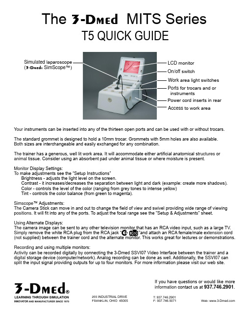
T5 QUICK GUIDEYour instruments can be inserted into any of the thirteen open ports and can be used with or withou t trocars.The standard grommet is designed to hold a 10mm trocar. Grommets with 5mm holes are also available. Both sizes are interchangeable and easily exchanged for any combination.The trainer has a generous, well lit work area. It will accommodate either artificial anatomical st ructures or animal tissue. Consider using an absorbent pad under animal tissue or where moisture is present.Monitor Display Settings:To make adjustments see the “Setup Instructions”Brightness - adjusts the light level on the screen. Contrast - it increases/decreases the separation between light and dark (example: create more shadows). Color - controls the level of the color (ranging from grey tones to intense yellow) Tint - controls the color balance (from green to magenta).Simscope ™ Adjustments:The Camera Stick can move in and out to change the field of view and swivel providing wide range of viewing positions. It will fit into any of the ports. To adjust the focal range see the “Setup & Adjustment s ” ing Alternate Displays:TheSimply tension cord (not Recording and using multiple monitors:Activity can be recorded digitally by connecting the 3-Dmed SSVI07 Video Interface between the trai ner and a digital storage device (computer/network). Analog recording can be done as well. Additionally, the SSVI07 can split the input signal providing outputs for up to four monitors. For more information please visit our web site.If you have questions or would like moreinformation contact us at .937.746.29013Dmed ®The MITS Series3Dmed LCD monitor Work area light switchesPorts for trocars and orinstrumentsPower cord inserts in rear Access to work areaOn/off switchSimulated laparoscope(3Dmed -® SimScope ™)Size & Weight Length: 20-1/4”Width: 12-7/8”Height: 11-3/8”Weight: 18 lbs.SETUP INSTRUCTIONS Thank you for purchasing the fromT5-RM3-Dmed. Each unit has been fully testedprior to shipment and is easy to setup and use...ModelT5-RM1. Lift the lid by the black knob to open.2. To install the Simscope™ see the separate instruction sheet included3. The power cord is stored inside the Trainer. Remove the cord by unhookingthe black Rip-Tie® strap. The cord can be secured back in the strap fortransportation or storage. Warning: Do not transport or ship the trainer withoutsecuring the cord tightly in the strap or damage to the screen could result!4. Connect the power cord to the receptacle at the back of the Trainer. Plugopposite end into a standard 100-120v AC outlet.5. After power has been supplied to the trainer, if the screen is not illuminatedpress the power button labeled “ ”. Press it for one second then release. Thescreen will come on in about three seconds. The LED light should turn fromorange to green indicating that power is supplied to the monitor and that asignal is being received. To turn the monitor off: press the “ ” button for onesecond and release.6. To illuminate the work area use one or both of the black rocker switcheslabeled “ ” that are located on the right side toward the back.7. If monitor adjustments are needed, press the button above the “ ” symbol.To scroll through the different controls press the “ ” or “ ” button on eithersideadjustments to that function press the “ ” or “ ” button on either side of the“ ” symbol. The “ ” button should be set to “AV”.NOTE: The monitor is a Liquid Crystal Display (LCD) and care must beexercised regarding the surface of the screen. To clean: use a soft cotton clothlightly dampened with water, vinegar (diluted w/water) or isopropyl alcohol. Donot Neverapply any cleaning solutions directly onto the screen. use cleaning products that contain abrasives or strong solvents. To prolong the life of themonitor and light turn them off when not in use.Size & WeightLength: 21”Width: 13.5”Height: 12.25”Weight: 23 lbs.ModelT5-RMW/ MODULAR MONITOR FOR REMOTE PEDESTAL Using the Screen Module on the Pedestal (Please read the entire procedure and refer to the figures as directed before proceeding)Transferring to the Pedestal 1.To separate the pedestal from the trainer:(with the screen module closed and latched)grab the black handle on the back of the trainer and pull upwhile holding down the pedestal below.They are secured with Velcro ®so there will be resistance.2.Once separated,fold the pedestal 90ºalong the length (hinged)and stand it vertically with the slots to receive the monitor at the top.Place it near the trainer (fig.1)3.Unlatch the screen module and leave it in the closed position.Locate the black thumbscrews on the back of the module (fig.2)and remove them.4.Grasp the screen module by the knob and the near locating tab (fig.3).Lift the assembly at the front (knob)slightly then proceed to lift the assembly straight up clearing it from the mounting flange on the hinge.5.Position the tabs on the bottom of the screen module into the slots on the pedestal (fig.4)until they are fully seated.Make sure the screen is toward the holes in front of the slots and that the thumbscrews and their retaining chains are positioned in front of the pedestal (fig.4).6.Continue to hold the screen assembly while securing it to the pedestal with the thumbscrews through the pedestal (fig.5).Tighten securely!Returning to the Trainer Body1.Position the mounting flange for the module in the upright position (fig.6).2.Hold the screen module while removing the thumbscrews that retain it to the pedestal (fig5).3.Remove the module from the pedestal and feed the black cord back into the trainer body as you guide it into position on the mounting flange (fig.7).Avoid pinching or twisting of the cord.The screen module must be in the horizontal position when placed on the mounting flange.4.When fully seated on the flange,secure the thumbscrews through the back of the module to the mounting flange.If you have questions or would like more information contact us at .937.746.29013Dmed ®The MITS Series3Dmed fig.1fig.2fig.3fig.4HOLE TO FRONT THUMBSCREWS & CHAINS TO FRONTThe SIMSCOPE™3Dmed SETUP & ADJUSTMENTS 1. The Simscope™ can be installed in any port location. Simply remove the gray grommet from the desired location. To do this press the outer edge of the grommet in toward the center then down into the trainer. (Fig.1). Figure 1.2. Insert the camera end of the Simscope™ into the hole (fig. 2). Grasp the swivel collar and press into the open hole until it “snaps”into place.Figure 27. To remove the Simscope™ grasp the swivel collar placing your forefinger under the tension adjustment boss for leverage,and pull out with a rocking motion (fig. 3). 5. To increase the resistence of the ball joint movement: tighten the three phillips screws (“A” fig. 3) with a #1 Phillips screwdriver. Adjustin small increments. Do not over tighten!Figure 48. To replace a grommet, squeeze it on opposite sides until it is narrower than the hole and fit the slot in the grommet over the edge of the hole (fig. 4). Work your way around the hole.Figure 3NOTE: Please remove lens cap before using.9. If there’s a need to adjust the focus of the camera lens you must first loosen the set screw in the side of the lens body with a .05” hex key (Allen™ wrench). Adjust the focus by screwing the lens in or out then gently secure the set screw to maintain that setting.9v DC If you have questions or would like more information contact us at .937.746.29013Dmed ®A- RECEPTACLE FOR SIMSCOPE VIDEO CAMERA (LARGE MODELS)9v DC220-240v AC-DISPLAY VALUESSYMBOLS LEGEND-EIf you have questions or would like moreinformation contact us at .937.746.29013Dmed PLEASE READ THIS WARRANTYIn order to provide warranty or future service please contact us via e-mail at:******************prior to taking any action.This will help expedite the process.Often,problems can be resolved by e-mail or phone.3-Dmed warrants this Product against defects in material or workmanship subject to the following conditions:1.MONITOR and CAMERA:These items are covered by their manufacturer ’s warranty for a period of one year.3-Dmed will act as liaison in the case of your claim,but final determination of coverage is the manufacturer ’s decision.BOR:For a period of one year from the date of purchase,if 3-Dmed determines the Product (part)to be defective,we will repair or replace the Product (part),at no charge.After the warranty period,we will provide an estimate for labor charges upon request.3.PARTS:3-Dmed will replace defective parts with new or rebuilt replacements for a period of one year.After the warranty period,parts are available through 3-Dmed and pricing will be provided upon request.TO OBTAIN WARRANTY SERVICE:YOU MUST obtain a RETURN AUTHORIZATION number via phone or e-mail BEFORE sending back the unit.The Product must be sent in its original packaging,or packaging affording an equal degree of protection,to 3-Dmed with insurance for its full value.Uninsured parcels are sent at YOUR RISK for loss or damage.This warranty does not cover user cosmetic damage or damage due to acts of God,accident,misuse,abuse,negligence,or modification to any part of the Product.This warranty does not cover damage due to improper operation or maintenance,connection to improper voltage supply,or attempted repair by anyone other than a trained technician at 3-Dmed.This warranty is invalid if the factory-applied serial number has been altered or removed from the Product.If you have questions or would like moreinformation contact us at .937.746.29013Dmed 。


Simplify complex motor-drive troubleshooting with guided test setups and automated drivemeasurements that provide reliable, repeatable test results.The new Fluke MDA 510 and MDA 550 Motor-Drive Analyzers save time and eliminate the hassle of setting up complex measurements, while simplifying the troubleshooting process. Simply select a test and the step-by-step guided measurements show youwhere to make voltage and current connections, while the preset measurement profiles ensure you will capture all the data you need for each critical motor-drive section—from the input to the output, the DC bus, and the motor itself. From basic to advanced measurements, the MDA-500 Series has you covered, and with a built-in report generator you can quickly and easily generate as-found, and as-left reports with confidence.The MDA-510 and MDA-550 are the ideal portable motor-drive analysis test tools, and can help safely locate and troubleshoot typical problems on inverter type motor-drive systems.• • ••••KEY MEASUREMENTSInverter output voltage, DC bus voltage and ripple voltage, harmonics, unbalance THREE POWERFUL TEST TOOLS IN ONEMotor-drive analyzer, waveform analyzer and recording data logger all in oneHIGHEST SAFETY RATING IN THE INDUSTRY600 V CAT IV/1000 V CAT III rated for use at the service entrance and downstreamThe Fluke MDA-510 and MDA-550 Motor Drive Analyzers use guided test measurements to make analysis easier than everDrive inputMeasure input voltage and current to quickly see whether values are within acceptable limits by comparing the drive’s nominal rated voltage to the actual supplied voltage. Then, check the input current to determine if the current is within the maximum rating and the conductors are suitably sized. You can also check whether the harmonic distortion is within an acceptable level by visu-ally inspecting the waveform shape or by viewing the harmonics spectrum screen (MDA-550) which shows both the total harmonic distortion and individual harmonics.Voltage and current unbalanceCheck the voltage unbalance at the input terminals so you canensure the phase unbalance is not too high (> 6-8 %), and that thephase rotation is correct. You can also check the current unbalance, as excessive unbalance may indicate a drive rectifier problem.Extended harmonic measurementsExcessive harmonics are not just a threat to your rotating machines but also to other equipment connected to the electrical powersystem. The MDA-550 provides the ability to discover the harmon-ics of the motor-drive but can also discover the possible effects of inverter switching electronics. The MDA-550 has three harmonic ranges, 1st to 51st Harmonics, 1 to 9 kHz and 9 kHz to 150 kHz giving the ability to detect any harmonic pollution problems.DC busIn a motor-drive the conversion of AC to DC inside the drive is critical, having the correct voltage and adequate smoothing with low ripple is required for the best drive performance. High ripple voltage may be an indicator of failed capacitors or incorrect sizing of the connected motor. The record function of the MDA-500 Series can be used to check DC bus performance dynamically in the oper-ating mode while a load is applied.Drive outputCheck the output of the drive focusing both on voltage to frequency ratio (V/F), and voltage modulation. When high V/F ratio measure-ments are experienced, the motor may overheat. With low V/Fratios, the connected motor may not be able to provide the requiredtorque at the load to sufficiently run the intended process.Drive input step-by-step guided measurement connectionsDrive output waveform with auto triggeringExtended harmonics spectrum from 9 kHz to 150 kHzVoltage modulationMeasurements of the Pulse Width Modulated signal are used to check for high voltage peaks which can damage motor winding insulation. The rise time or steepness of impulses is indicated by the dV/dt reading (rate of voltage change over time), this should be compared to the motor’s specified insulation. The measure-ments can also be used to measure switching frequency to identify whether there is a potential issue with electronic switching, or with grounding, where the signal floats up and down.Motor inputEnsuring that voltage is being supplied at the motor input termi-nals is key, and the selection of cabling from drive to the motoris critical. Incorrect cabling selection can result in both drive and motor damage due to excessive reflected voltage peaks. Checking that the current present at the terminals is within the motor rating is important as over current condition could cause the motor to run hot, decreasing the life of the stator insulation which can result in the early failure of the motor.Motor shaft voltageVoltage pulses from a variable speed drive can couple from a motor’s stator to its rotor, causing a voltage to appear on the rotor shaft. When this rotor shaft voltage exceeds the insulating capac-ity of the bearing grease, flashover currents (sparking) can occur, causing pitting and fluting of the motor bearing race, damage that can cause a motor to fail prematurely. The MDA-550 Series ana-lyzers are supplied with carbon fiber brush probe tips that can easily detect the presence of destructive flashover currents, while the impulse amplitude and count of events will enable you to take action before failure occurs. The addition of this accessory and capability of the MDA-550 allows you to discover potential damage without investing in expensive permanently installed solutions.Step-by-step guided measurements ensure you have the data you need, when you need itThe MDA-500 Series is designed to help you quickly and easily test and troubleshoot typical problems on three-phase and single-phase inverter type motor-drive systems. The on-screen information, and step-by-step setup guidance make it easy to con-figure the analyzer and get the drive measurements you need to make better maintenance decisions, fast. From power input to the installed motor, the MDA-500 provides the measurement capabilityfor the fastest motor-drive troubleshooting.Voltage modulation with zoomMotor shaft voltage discharge event countsQuick and easy measurement setup1) Press ‘Motor Drive Analyzer’ button and select‘Drive Measurement Location’.2) Use the on-screen context information tofurther guide you to successful setup andmeasurement.3) Choose the measurement.4) Select the measurement method/option.5) Connect the test probes according to the dia-gram. Once complete press ‘Next’.6) The analyzer will then automatically trigger,and configure the reading for the optimummeasurements.Reporting and analysisThe MDA-500 Series simplifies the process of gathering data and writing test reports with abuilt-in report generator.At each test point or measurement there is the option to create, update or modify a report. Simply press ‘SAVE TO REPORT’ and select the appropri-ate screens to save into a text based report file. By performing the step-by-step guided measure-ments a comprehensive report can be created directly from the instrument to document the entire troubleshooting process.Input the report name. The single report encom-passes all recorded measurements and can easily be shared with other users and used for motor-drive benchmarking, and for comparing data nowand in the future.Featured measurementsSpecificationsOrdering informationMDA-510Motor drive analyzer, 4 channel, 500 MHzMDA-550Motor drive analyzer, 4 channel, 500 MHz with motor shaft and harmonicsIncludes1x BP 291 li-ion battery pack, 1x BC190 charger/power adapter, 3x VPS 100:1 high voltage probes with alligator clips, 1xVPS410-II-R 10:1 500MHz voltage probe, 1x i400s ac current clamp, 1x C1740 carrying case, 1x 2 GB USB drive with manuals and FlukeView™2 softwareMDA-550 also includes 1x SVS-500 shaft voltage set (3x brush, probe holder, two-piece extension rod and magnetic base), additional 2x i400s ac current clampsAdditional accessoriesSVS-500 set of 3x brushes, probe holder, two-piece extension rod and magnetic baseSB-500 set of 3x replacement brushes*In addition, Fluke 190 series II ScopeMeter™ Test Tools acces-sories are also supported by the MDA-500 Series Fluke CorporationPO Box 9090, Everett, WA 98206 U.S.A.Fluke Europe B.V.PO Box 1186, 5602 BDEindhoven, The NetherlandsFor more information call:In the U.S.A. (800) 443-5853 orFax (425) 446-5116In Europe/M-East/Africa +31 (0) 40 2675 200 or Fax +31 (0) 40 2675 222In Canada (800)-36-FLUKE orFax (905) 890-6866From other countries +1 (425) 446-5500 or Fax +1 (425) 446-5116Web access: ©2018 Fluke Corporation.Specifications subject to change without notice. Printed in U.S.A. 6/2018 6011207b-enModification of this document is not permitted without written permission from Fluke Corporation. Fluke. Keeping your worldup and running.®。
800-238-7474********************10u Universal voltage range of 208-480V on PMPU provides the flexibility to cover a variety of applications with one unit u Protects against phase loss,phase reversal, phaseunbalance, undervoltage and overvoltage u Variety of user-selectable andadjustable settings for the ultimate in three-phase protection u Automatic & Manual Reset inSame Unit u Multi-Color LED indicatesnormal condition and provides specific fault indication to simplify troubleshooting u Compact plug-in case utilizingindustry-standard 8 pin octal socket u 10A SPDT output contacts uThe PMP Series Phase Monitor Relays utilize a microprocessor-based design to provide protection against phase loss, phase reversal, phase unbalance,undervoltage and overvoltage. The PMPU is a universal voltage product that works on any three-phase system voltage from 208-480V (a separate 120V version is available). These devices are designed to be compatible with most Wye or Delta systems with no connection to Neutral required. PMP Series products protect against unbalanced voltages or single phasing regardless of any regenerative voltages.The relay is energized when the phase sequence and all voltages are correct.Any one of five fault conditions will de-energize the relay. As standard, re-energization is automatic upon correction of the fault condition. Manual reset is available if a momentary N.C. switch is wired to the appropriate terminals. A multi-color LED indicates normal condition and also provides specific fault indication to simplify troubleshooting.The PMP Series offers a variety of user-adjustable settings. The percent phase unbalance is adjustable from 2-10%, and also has a Disable setting for those applications where poor voltage conditions could cause nuisance tripping. The undervoltage drop-out can be set at 80-95% of operating voltage (overvoltage setting is fixed at 110% of nominal). The adjustable time delay drop-out on undervoltage (0.1-20 seconds) eliminates nuisance tripping caused by momentary voltage fluctuations. There is also an adjustable time delay (1-300 seconds) on both power up and restart after a fault has been cleared.p Phase-to-Phase (Line-to-Line).*Requires a 600V-rated socket when used on system voltages above 300V.n See Pages 80 & 81 for Sockets & Accessories .DIAGRAM 104PHASE MONITOR RELAYSPhase Loss, Phase Reversal, Phase Unbalance, and Under/Over Voltage PMP Series Plug-in(with appropriate socket)8/1111Hysteresis : 2 - 3%Load (Burden): Less than 3VATemperature : -28o to 65o C (-18o to 149o F)Mounting:Uses an 8 pin octal socket. Requires a 600V-rated socketwhen used on system voltages greater than 300V (Macromatic Product Number 70169-D--see Page 80).Indicator LED:Reset:As standard, reset is automatic upon correction of fault. When a momentary-contact N.C. switch is wired across the Manual Reset terminals (6 & 7), the unit switches to manual reset mode and remote manual reset is available.Approvals:Phase Loss:Unit trips on loss of any Phase A, B or C.Phase Reversal:Unit trips if rotation (sequence) of the three phases is anything other than A-B-C.Undervoltage:Adjustable from 80-95% of nominal voltage. Unit trips when the average of all three lines is less than the adjusted set point for a period longer than the adjustable time delay drop-out.Overvoltage:Fixed at 110% of nominal voltage. Unit trips when the average of all three lines is greater than the fixed set point for a period longer than the time delay drop-out.Phase Unbalance:Adjustable from 2 - 10% unbalance. Unit trips when any one of the three lines deviates from the average of all three lines by more than the adjusted set point. There is also a Disable setting adjustment that will turn off the Phase Unbalance Protection if nuisance tripping is a problem.Output Contacts:SPDT:10A @ 240V AC/30V DC, 1/2HP @ 240V AC Life:Mechanical: 10,000,000 operations Full Load: 100,000 operations Response Times:Power Up & Restart After Fault: 1 - 300 seconds adjustable Drop-out Due to Fault:Phase Loss & Reversal 100ms fixed Phase Unbalance 2 seconds fixedUndervoltage 0.1 - 20 seconds adjustable OvervoltageFixed Time Based on Inverse Time CurvePHASE MONITOR RELAYSPhase Loss, Phase Reversal, Phase Unbalance, and Under/Over VoltagePMP Series Plug-inApplication Data & DimensionsApplication DataDimensions1.7(43)2.9(74)3.0(77)2.4(60)All Dimensions in Inches (Millimeters)Low Voltage & EMC Directives EN60947-1, EN60947-5-1File #E1094668/11withappropriate socketFile #E109466。
GE Healthcare实施您ÄKTApurifier的首次运行重要用户信息所有用户必须阅读整本手册以充分理解ÄKTApurifier的使用安全。
WARNING(警告)警告标识强调必须严格遵循指令以避免人身伤害。
在说明书完全弄懂和所有规定条件都具备后才能开始动手操作。
Caution(小心)小心标识用于引起注意以避免人身伤害,必须遵循指令和条件以避免毁坏产品和其它设备。
在说明书完全弄懂和所有规定条件都具备后才能开始动手操作。
Note(注意)注意标识用于指出对产品的无故障及最佳使用的重要信息。
CE证书产品符合适用于CE规定的所有要求。
相应合格证的复印件函索即寄。
CE标志和相应合格证对该仪器是有效的。
当仪器– 连接到其它标有CE标志的 GE Healthcare 仪器上,或,– 连接到本手册中推荐或所述的其它仪器上, 和,– 除了在本手册中提到的变更外,按 GE Healthcare 所提供的说明使用。
警告本产品为A类产品。
在局部环境下,本产品可能引起无线电干扰,在此情况下用户可能需要进行适当的测量。
销售条款和规定除非另有书面协议,在 GE Healthcare 集团供应范围内,所有售出货物和服务都服从公司的销售条款和规定。
这些销售条款和规定的复印件函索即寄。
如果您对本产品有任何意见,我们将乐意接受。
请寄往:GE HealthcareSE-751 84 UppsalaSweden商标水滴图样, ÄKTA, ÄKTApurifier, UNICORN and Superloop 均为 GE Healthcare 的商标。
Amersham 和 Amersham Biosciences 为 GE Healthcare 的商标。
.Windows为Microsoft Corporation 的注册商标。
办事处地址GE HealthcareSE-751 84 UppsalaSwedenGE Healthcare 香港办事处香港九龙望角亚皆老街8号朗豪坊办公大楼12楼电话:(852)2100 6314传真:(852)2100 6338GE Healthcare 北京办事处北京市经济开发区永昌北路1号电话:(010)5806 9689传真:(010)6787 1162邮编: 100176GE Healthcare 上海办事处上海市虹桥开发区兴义路8号万都中心2401室电话:(021)5257 4650-67337传真:(021)5208 1282邮编: 200336GE Healthcare 广州办事处广州市建设六马路33号宜安广场1212室电话:(020)8363 3828-67961,67956 传真:(021)8363 3291邮编: 510060800热线:800-810-9118© GE Healthcare Life Sciences 2003版权- 所有权利受保护目录1关于本指南 (5)1.1 必要条件 (5)1.2 印刷上的规定 (5)2系统和软件 (6)2.1 概论 (6)2.2 UNICORN综述 (9)2.3 帮助 (11)3 建立方法 (12)4准备运行系统 (15)4.1 系统连接 (15)4.2 系统的一般准备 (16)4.2.1充满入口管道 (17)4.2.2 充满样品环 (17)5开始运行 (18)6查看运行 (23)7查看和打印结果 (26)7.1 查看 (26)7.2 打印和生成报告 (29)8缓冲液制备 (32)9探索 (34)10进一步应用 (36)索引(略)简短说明 (38)注意:本手册所涉及内容以英文原版为准1关于本指南本指南是为不熟悉UNICORN™ 软件和ÄKTApurifier™的用户而写的。
Page 1/7Electronics & SoftwareKistler LabAmpCharge amplifier and data acquisition for multi-channel measurement5167A x 0_003-277e -10.18© 2017 ... 2018 Kistler Group, Eulachstrasse 22, 8408 Winterthur, Switzerland . Kistler Group products are This information corresponds to the current state of knowledge. Kistler reserves the right to make technical changes. Liability for consequential damage resulting Type 5167Ax0This universal laboratory charge amplifier can be used wher-ever mechanical quantities are measured with multiple piezo-electric sensors. It covers slow, quasi-static signals as well as dynamic processes.Piezoelectric sensors produce an electric charge which varies in direct proportion with the load acting on the sensor. The amplifier converts this charge directly into digital values or a proportional output voltage.• 4- or 8-channel amplifier for piezoelectric sensors• Integrated 24-bit data acquisition with up to 100 kSps per channel• Continuous digital signal processing at minimal latency • Fully flexible low-pass, high-pass and notch filter adjust-ment• Low-noise design• 4 or 8 analog outputs with fully flexible 2-point scaling and internal routing• Status indication via LED• Virtual channels for real-time calculations using one or more sensor channels• Configuration and control in a standard web-browser • Virtual instrument driver for LabVIEW• Two Ethernet interfaces with included switch functionality • Digital inputs for Reset/Measure and TriggerDescriptionThe Kistler LabAmp Type 5167Ax0 is not only an outstanding low-noise charge amplifier for dynamic signals but also a pow-erful data acquisition device delivering the digitized measure-ment values directly to a host computer for further analysis. It is configured and operated in a web-interface, conveniently accessible by a standard web-browser.Thanks to advanced signal processing technology, the Kistler LabAmp Type 5167Ax0 offers impressive flexibility. The fre-quencies of the high-pass, low-pass and notch filters can be directly entered as numeric values in Hertz. The input signals can be flexibly routed to the analog outputs.The graphical user interface not only offers a simple and in-tuitive way to configure the device but also displays different measurement values (e.g. live value, peak value, root mean square). The virtual channel functionality allows real-time summation of different input signals.Furthermore, the browser-based data download allows the ac-quired data to be processed in an analysis software. For more advanced tasks or direct analysis, the amplifier can be inte-grated directly into LabVIEW thanks to the provided Virtual Instruments Driver.ApplicationWith its ability to measure quasi-static signals, Type 5167Ax0 is particularly suitable for multi-component force measure-ments in various applications in the laboratory as well as in research and development. For example, wheel force mea-surement on a tire test stand, reaction force measurements on engine-transmission units, monitoring of forces and torques in vibration tests etc.For higher channel counts, the synchronization feature allows acquiring data from multiple Type 5167A... devices. Kistler LabAmp Type 5165A... devices can be synchronized with the Type 5167A... as well which allows the combined acquisition of pure dynamic signals from other charge or Piezotron (IEPE)sensors or any voltage signals.Page 2/75167A x 0_003-277e -10.18© 2017 ... 2018 Kistler Group, Eulachstrasse 22, 8408 Winterthur, Switzerland Tel.+41522241111,****************,. Kistler Group products are This information corresponds to the current state of knowledge. Kistler reserves the right to make technical changes. Liability for consequential damage resulting Technical dataConnections Number of channels Type 5167A404Type 5167A808Input connector type BNC neg.Analog output connector type BNC neg.Ethernet interface 2xRJ45Remote control D-Sub 9fCharge input Measuring ranges pC ±100 … 1 000 000Frequency range (–3 dB)≤195 000 pC Hz ≈0 … >45 000>195 000 pC Hz≈0 … >15 000Input noise (typ.)1 Hz ... 100 kHz 100 pC pC rms 0,0091 000 pC pC rms 0,01910 000 pC pC rms 0,43100 000 pC pC rms 4,01 000 000 pC pC rms 8,51 Hz ... 10 kHz 100 pC pC rms 0,0071 000 pC pC rms 0,01210 000 pC pC rms 0,25100 000 pC pC rms 3,01 000 000 pCpC rms3,4Drift, measuring mode DC (Long)at 25 °C, max. relative humidity RH of 60 % (non-condensing)pC/s <±0,03at 25 °C, max. relative humidity RH of 70 % (non-condensing)pC/s <±0,05at 50 °C, max. relative humidity RH of 50 % (non-condensing)pC/s<±0,2Measure-jumpCompensatedMeasure-jump pC <±0,1Correction time ms<20Measurement uncertaintyMeasuring range <100 pC %<1Measuring range ≥100 pC %<0,5Temperature coefficient, typ.ppm/°C <50Linearity error, typ.%FSO <0,01Crosstalk between channels dB <–80Sensor impedanceΩ>1010Voltage output Nominal output rangeV ±10Output impedanceΩ10Max. common mode voltage between input and output ground V50Output noise (all ranges)1 Hz ... 100 kHz, typ.mV rms 0,0301 Hz ... 10 kHz, typ.mV rms 0,012Frequency range (–3 dB)Hz 0 ... 100 000Group delay (input to output, filters off)μs ≤14Zero errormV <±2DAC resolution (analog out)Bit16Data acquisition ADC resolutionBit 24Internal ADC sampling ratekSps 625Acquisition data rate per channel (adjustable)kSps100Note: For the data acquisition with ≥25 kSps an anti-aliasing filter is automatically set with a cut-off frequency of 0,3 ... 0,43 x selected output update rate.High-Pass filter Order1.Analog high-pass filter Time constant DC (Long)<45 000 pC s >10 000≥45 000 pC s>100 000Time constant Short <45 000 pCs 10≥45 000 pC s 110Tolerance (typ.)%20Digital High-Pass Filter Cutoff-frequency (–3 dB) selection in 0,1 Hz steps Hz ≥0,1 ... 10 000Tolerance (typ.)%<1Digital Low-Pass filter Filter type Bessel or ButterworthOrder2./4.Cutoff-frequency (–3 dB) selection in 0,1 Hz steps Hz ≥10Tolerance (typ.)%<1Page 3/75167A x 0_003-277e -10.18© 2017 ... 2018 Kistler Group, Eulachstrasse 22, 8408 Winterthur, Switzerland Tel.+41522241111,****************,. Kistler Group products are This information corresponds to the current state of knowledge. Kistler reserves the right to make technical changes. Liability for consequential damage resulting Technical data (continuation)Digital Notch filter Center frequency (–3 dB) selection in 0,1 Hz steps Hz ≥10Tolerance (typ.)%<1Q factor 0,9 ... 1 000Virtual channels Number of channelsType 5167A402Type 5167A806Ethernet interface Data rateMBit100Remote control(Digital input and 24 V supply)Remote measure and trigger with 10 k Ω pullup to +5 V Connector type D-Sub 9fInput levelHigh (Reset, Stop trigger)V>3,5orInput openLow (Measure, Start trigger)V <1Max. input voltage V ±30Supply (output)V DC +24/±10 %Output current (short circuit proof)mA ≤200OperationAll settings are configured in a standard web-browser through the graphical user interface. Simply connect to the Kistler LabAmp Type 5167A... by its network name and start working.Power supply requirements Supply voltage range VDC 18 (30)Power consumption W <15Socket for barrel jack plug (IEC 60130-10 Type A) mm5,5x2,5x9,5Power supply requirements– galvanic isolation – PE and GND not connectedGeneral dataOperating temperature range °C 0 ... 60Storage temperature range °C –10 (70)Rel. humidity, not condensing %≤90Degree of protection (EN 60529)IP20Outer dimensions incl. feet and connectors (WxHxD)Type 5167A40mm ≈218x50x223Type 5167A80mm≈218x93x223WeightType 5167A40kg 1,2Type 5167A80kg1,8Fig. 1: Web user interface Type 5167Ax0A simple data acquisition is also implemented, offering a data download controlled by a start/stop button. In addition, an API is available to perform automated measuring tasks PC-based.Page 4/75167A x 0_003-277e -10.18© 2017 ... 2018 Kistler Group, Eulachstrasse 22, 8408 Winterthur, Switzerland Tel.+41522241111,****************,. Kistler Group products are This information corresponds to the current state of knowledge. Kistler reserves the right to make technical changes. Liability for consequential damage resulting Block diagramFig. 2: Block diagram of the Kistler LabAmp Type 5167Ax0Sensor 1Sensor 2Sensor 3Sensor 4Sensor 5 (8)ControlPage 5/75167A x 0_003-277e -10.18© 2017 ... 2018 Kistler Group, Eulachstrasse 22, 8408 Winterthur, Switzerland Tel.+41522241111,****************,. Kistler Group products are This information corresponds to the current state of knowledge. Kistler reserves the right to make technical changes. Liability for consequential damage resulting DimensionsFig. 3: Dimensions of Kistler LabAmp Type 5167A40Page 6/75167A x 0_003-277e -10.18© 2017 ... 2018 Kistler Group, Eulachstrasse 22, 8408 Winterthur, Switzerland Tel.+41522241111,****************,. Kistler Group products are This information corresponds to the current state of knowledge. Kistler reserves the right to make technical changes. Liability for consequential damage resulting Fig. 4:Dimensions of Kistler LabAmp Type 5167A80Page 7/75167A x 0_003-277e -10.18© 2017 ... 2018 Kistler Group, Eulachstrasse 22, 8408 Winterthur, Switzerland Tel.+41522241111,****************,. Kistler Group products are This information corresponds to the current state of knowledge. Kistler reserves the right to make technical changes. Liability for consequential damage resulting Included accessories Type/Mat. No.• Calibration sheet –• Quick-start guide –• Power supply 24 V 5779A2 incl. country-specific plug • Ethernet cable, l = 2 m tbd Optional accessories Type/Mat. No.• 19" rack mounting tablet for 5748A1 Type 5167A40• Dummy panel for empty 5748A2 19" position (1 height unit)• 19" rack mounting tablet for 5748A3 Type 5167A80• Dummy panel for empty 5748A4 19" position (2 height units)• DynoWare software 2825A-03-2 Full license with HASP license key • Inductive proximity switch 2233B generates an external trigger signal tostart measurementOrdering keyLabVIEW is a registered trade mark of National Instruments Corporation.。
Products Solutions Services TI00193C/07/EN/14.1371236586Technical InformationLiquisys M CLM223/253Conductivity/Resistivity MeasurementTransmitter for conductive and inductive sensorsApplication•Ultrapure water•Water treatment•Ion exchanger, reverse osmosis•Cooling water desalinization•SewageYour benefits•Field or panel-mounted housing•Universal application•Simple handling–Logically arranged menu structure–Ultrasimple two-point calibration•Safe operation–Overvoltage (lightning) protection–Manual contact control and user-defined alarm configurationThe basic unit can be extended with:•2 or 4 additional contacts for use as:–Limit contacts (also for temperature)–P(ID) controller–Timer for simple rinse processes–Complete cleaning with Chemoclean•Plus package:–User defined current output characteristics–Ultrapure water monitoring acc. to USP (United States Pharmacopeia) and EP(European Pharmacopoeia) (conductive)–Polarization detection (conductive)–Concentration measurement–Process Check System (PCS): live check of the sensor•HART or PROFIBUS-PA/-DP•2nd current output for temperature, main measured value or actuating variable•Current input for flow rate monitoring with controller shut off or for feedforwardcontrolLiquisys M CLM223/2532Endress+HauserFunction and system designFeatures of the basic versionConductive or inductiveTwo instrument versions for measurement with conductive (two electrode) sensors or inductive sensors are available. The use of inductive sensors that are less sensitive to soiling than conductive sensors is recommended for high conductivity measurement, concentration measurement or adhering media.Measuring of conductivity and resistivity (conductive)This is selected via the menu. During measurement, the value measured can be displayed in the other measuring mode. The temperature is displayed at the same time or, if desired, not shown at all.Temperature compensationThe following temperature compensation selections are available: •Linear•NaCl curve according to IEC 746•Ultrapure water NaCl (neutral compensation)•Ultrapure water HCl (acid compensation, also ammonia)The reference temperature is user defined, the standard value is 25 °C (77 °F).ConfigurationDifferent alarms are required depending on application and operator. Therefore the transmitterpermits independent configuration of the alarm contact and error current for each individual error. Unnecessary or undesirable alarms can be suppressed in this manner. Up to four contacts Up to two contacts can be used as limit contacts (also for temperature), to implement a P(ID) controller or for cleaning functions.Direct manual operation of the contacts (bypassing the menu) provides quick access to limit, control or cleaning contacts, permitting speedy correction of deviations.The serial numbers of the instrument and modules and the order code can be called up on the display.The cell constant can be edited and even calibrated for demanding special applications.Additional functions of the plus packageCurrent output configurationIn order to output wide measuring ranges while still achieving a high resolution in specific ranges, the current output can be configured as required via a table. This permits bilinear or quasi-logarithmic curves, etc.Polarization detectionPolarization effects in the boundary layer between the sensor and the medium to be measured limit the measuring range of conductive conductivity sensors.The transmitter can detect polarization effects using an innovative, intelligent signal evaluation process.Live checkThe live check issues an alarm when the sensor signal does not change over a defined period of time. This may be caused by blocking, passivation, separation from the process, etc.Ultrapure water monitoring acc. to USP (United States Pharmacopeia) and EP (European Pharmacopoeia)Ultrapure water monitoring according to USP <645> and EP means that the uncompensated conductivity and the temperature are measured and compared to a table.The transmitter (conductive with additional contacts) comes with the following functions:•Monitoring of "Water for Injection" (WFI) according to USP and EP •Monitoring of "Highly Purified Water" (HPW) according to EP •Monitoring of "Purified Water" (PW) according to EPThe user-adjustable pre-alarm indicates undesirable operating values in due time. Full compliance with USP or EP requires the use of a precisely calibrated sensor, for example, the CLS16.Liquisys M CLM223/253Endress+Hauser 3Concentration measurementThe conversion from conductivity to concentration is effected using four user-definable concentration curves . This permits concentrations to be displayed in %, ppm, mg/l or TDS (total dissolved solids).Adaptive calibration for determination of the installation factor (inductive)Inductive measuring sensors must normally be installed in pipes at a required minimum distance from the pipe wall. If this minimum distance is not observed, the measured value changes. The built-in adaptive calibration using the installation factor allows you to compensate for this once the sensor is installed.Second current outputThe second current output can be configured for temperature, main measured value (conductivity, resistivity, concentration) or actuating variable.Current inputThe current input of the transmitter allows two different applications: controller shut-down in case of lower flow rate violation or total failure in the main flow as well as feedforward control. Both functions are also combinable.Measuring systemA complete measuring systems comprises:•The transmitter Liquisys M CLM223 or CLM253•A sensor with or without an integrated temperature sensor•A measuring cable CYK71 (conductive), CPK9 for Condumax H CLS16 or CLK5 (inductive)Options: extension cable, junction box VBMComplete measuring system Liquisys M CLM223/2531234Conductive sensor CLS15Liquisys M CLM253Liquisys M CLM223Inductive sensor CLS54567Inductive sensor CLS50Conductive sensor CLS21Immersion assembly CLA111Liquisys M CLM223/2534Endress+HauserInputMeasured variables Conductivity, resistivity, temperature Measuring rangeCable specificationCell constantTemperature sensors Pt 100, Pt 1000, NTC 30KMeasuring frequencyBinary inputsCurrent input4to 20mA, galvanically separated Load: 260Ω at 20mA (voltage drop 5.2V)Conductivity (conductive):0 to 600 mS/cm (uncompensated)Conductivity (inductive):0 to 2000 mS/cm (uncompensated)Resistivity:0 to 200 M Ω⋅cmConcentration:0 to 9999 (%, ppm, mg/l, TDS)Temperature:-35 to +250 °C (-31 to +482 °F)Cable length (conductive):conductivity: max. 100 m (328 ft) (CYK71)resistivity: max 15 m (49 ft) (CYK71)Cable length (inductive):max 55 m (180 ft) (CLK5)Cable resistance CYK71:165 Ω/km (conductivity measurement)Adjustable cell constant:k = 0.0025 to 99.99 cm -1Conductivity, resistivity (conductive):170 Hz to 2 kHz Conductivity (inductive): 2 kHz Voltage:10to 50V Power consumption:max. 10mALiquisys M CLM223/253Endress+Hauser 5OutputOutput signal0/4 to 20 mA, galvanically separated, activeSignal on alarm 2.4 or 22 mA in case of an error Loadmaximum 500 Ω Linearization transmission behaviourResolutionmax. 700 digits/mAMin. distance for 0/4to 20mA signalIsolation voltage max. 350 V RMS /500 V DC Overvoltage protectionaccording to EN 61000-4-5HART Signal coding Frequency Shift Keying (FSK) + 0.5 mA via current output signal Data transfer rate 1200 Baud Galvanic isolationyesPROFIBUS PA Signal coding Manchester Bus Powered (MBP)Data transfer rate 31.25 kBit/s, voltage mode Galvanic isolationyes (IO-Module)PROFIBUS DP Signal coding RS485Data transfer rate 9.6 kBd, 19.2 kBd, 93.75 kBd, 187.5 kBd, 500 kBd, 1.5 MBd Galvanic isolationyes (IO-Module)Conductivity:Resistivity:Concentration:Actuating variable:Temperature:adjustable adjustable adjustable adjustable adjustableConductivity:Measured value 0 to 1.999 μS/cm 0.2 μS/cm Measured value 0 to 19.99 μS/cm 2 μS/cm Measured value 20 to 199.9 μS/cm 20 μS/cm Measured value 200 to 1999 μS/cm 200 μS/cm Measured value 2 to 19.99 mS/cm 2 mS/cm Measured value 20 to 2000 mS/cm 20 mS/cmResistivityMeasured value 0 to 199.9 k Ωcm 20 k Ωcm Measured value 200 to 1999 k Ωcm 200 k Ωcm Measured value 2 to 19.99 M Ωcm 2.0 M Ωcm Measured value 20 to 200 M Ωcm 20 M ΩcmConcentration no minimum distance Temperature15 °CLiquisys M CLM223/2536Endress+HauserAuxiliary voltage outputContact outputsLimit contactorControllerAlarmOutput voltage:15V ± 0.6Output current:max. 10mASwitching current with ohmic load (cos ϕ= 1):max. 2A Switching current with inductive load (cos ϕ = 0.4):max. 2A Switching voltage:max. 250V AC, 30V DC Switching power with ohmic load (cos ϕ = 1):max. 500 VA AC, 60W DC Switching power with inductive load (cos ϕ = 0.4):max. 500VA AC, 60W DC Pickup/dropout delay:0to 2000sFunction (adjustable):pulse length/pulse frequency controller Controller response:PIDControl gain K p :0.01to 20.00Integral action time T n :0.0to 999.9min Derivative action time T v :0.0to 999.9min Period for pulse length controller:0.5to 999.9 s Frequency for pulse frequency controller:60to 180 min -1Basic load:0to 40% of max. set valueFunction (selectable):Latching/momentary contactAlarm threshold adjustment range:Conductivity, resistivity, concentration,temperature, USP, EP: complete measuring range Alarm delay:0to 2000s (min)Liquisys M CLM223/253Protocol specific data HARTManufacturer ID11hDevice type code0092h (ind. measured), 0093h (cond. measured)Transmitter specific revision0001hHART specification 5.0DD files /hartLoad HART250Device variables None (dynamic variables PV, SV, only)Features supported-PROFIBUS PAManufacturer ID11hIdent number1515hDevice revision11hProfile version 2.0GSD files /profibusGSD file versionOutput values Main value, temperature valueInput values Display value of PLCFeatures supported Device locking: The device can be locked by hardware orsoftware.PROFIBUS DPManufacturer ID11hIdent number1521hProfile version 2.0GSD files /profibusGSD file versionOutput values Main value, temperature valueInput values Display value of PLCFeatures supported Device locking: The device can be locked by hardware orsoftware.Endress+Hauser7Liquisys M CLM223/2538Endress+HauserPower supplyElectrical connectionThe instrument has protection class II and is generally operated without protective earth connection. To ensure the measuring stability and the function for conductive sensors you have to connect the outer screen of the sensor cable to the PE terminal.Electrical connection of the transmitterA B C D E F G H Sensor (conductive)Sensor (inductive)Temperature sensorSignal output 1 conductivity Signal output 2 variable Binary input 1 (Hold)Binary input 2 (Chemoclean)Aux. voltage outputI J K L M N O Alarm (current-free contact position)Relay 1 (current-free contact position)Relay 2 (current-free contact position)Relay 3 (current-free contact position)Relay 4 (current-free contact position)Current input 4...20mA Power supplyLiquisys M CLM223/253Endress+Hauser 9Connection of sensorYou require screened special measuring cables to connect conductivity sensors to the transmitter. To extend the measuring cable, use junction box and extension cable (see accessories).Supply voltageDepending on ordered version:100/115/230 V AC +10/-15 %, 48 to 62 Hz 24 V AC/DC +20/-15 %Fieldbus connectionPower consumption max. 7.5 VAMains protection Fine-wire fuse, medium-slow blow 250 V/3.15 ACircuit breakerNOTICEThe device does not have a power switch‣You must provide a protected circuit breaker in the vicinity of the device.‣This must be a switch or a power-circuit breaker and you must label it as the circuit breaker for thedevice.‣At the supply point, the power supply for the 24 V versions must be isolated from dangerous livecables by double or reinforced insulation.Connection of conductive sensorsConnection of inductive sensorsHART Supply voltagen/a, active current outputs Integrated reverse voltage protectionn/a, active current outputsPROFIBUS PA Supply voltage 9 V to 32 V, max. 35 V Polarity sensitiveno FISCO/FNICO compliant acc. to IEC 60079-27noPROFIBUS DP Supply voltage 9 V to 32 V, max. 35 V Polarity sensitiven/a FISCO/FNICO compliant acc. to IEC 60079-27noLiquisys M CLM223/25310Endress+HauserPerformance characteristicsReference temperature 25 °C (77 °F); adjustable for the compensation of the medium temperature ResolutionMaximum measured error 1)Repeatability 1Temperature compensationTemperature offset ±5 °C; for the adjustment of the temperature displayConductivity:Temperature:depending on the measuring range: 0.001 μS/cm to 1.999μS/cm and k 0.5 cm -10.1 °C1) acc. to IEC 746-1, for nominal operating conditionsConductivity:Display:max. 0.5 % of measured value ± 4 digits Conductivity signal output:max. 0.75 % of current output range Resistivity:Display:max. 0.5 % of measured value ± 4 digits Resistivity signal output:max. 0.75 % of current output range Temperature:Display:max. 1.0 % of measuring range Temperature signal output:max. 1.25 % of current output range Conductivity:max. 0.2 % of measured value ± 2 digits Resistivity:max. 0.2 % of measured value ± 2 digitsRange:-35 to +250 °C (-31 to +482 °F)Types of compensation:uncompensated, linear, NaCl, table;conductive only: ultrapure water NaCl, ultrapure water HClInstallation Installation instructionsField instrumentMounting on pipes1 - 3Mounting screws and mounting plateView into the field instrument1234Removable electronics box Partition plate Terminal blocks FuseWall mounting of the field instrument 1Mounting holes 2 Protecting capMounting of the field instrument with mounting post and weather protection cover 1 - 3Mounting holesØ6/Ø0.24Dimensions panel-mounted instrumentInstallation of the panel-mounted instrument 1Wall of control cabinet 2Gasket 3Tensioning screws*Required installation depth92/ 3.62+0.5+0.0292/ 3.62+0.5+0.02EnvironmentAmbient temperature -10 to +55 °C (+14 to +131 °F)Storage temperature –25 to +65 °C (-13 to +149 °F)Electromagnetic compatibility Interference emission and interference immunity as per EN 61326-1:2006, EN 61326-2-3:2006Ingress protectionElectrical safety according EN/IEC 61010-1:2001, Installation Category II, for use up to 2000 m above sea level CSAApparatus with CSA General Purpose Approval are certified for indoor use.Relative humidity 10 to 95%, non-condensingPollution degreeThe product is suitable for pollution degree 2.Mechanical constructionDimensionsWeightMaterialTerminalsPanel mounted instrument:IP 54 (front), IP 30 (housing)Field instrument:IP 65 / tightness acc. to NEMA 4XPanel mounted instrument:96x 96x 145mm (3.78 x 3.78 x 5.71 inches)Installation depth: approx. 165mm (6.50")Field instrument:247x 170x 115mm (9.72 x 6.69 x 4.53 inches)Panel mounted instrument:max. 0.7kg (1.5 lb)Field instrument:max.2.3kg (5.1 lb)Housing of panel mounted instrument:Polycarbonate Field housing:ABS PC FrFront membrane:Polyester, UV-resistant Cross sectionmax. 2.5 mm 2OperabilityOperating concept All instrument control functions are arranged in a logical menu structure. Following access code entry,the individual parameters can be easily selected and modified as needed.Display elementsOperating elements1LC display for display of measured values, configuration data and current menu field2Field for user labelling3 4 main control keys for calibration and instrument configuration4Key for switching between automatic/manual operation of the relays5LED indicators for limit contactor relay (switch status)6LED indicator for alarm function7Display of active contact and key for relay switching in manual modeThe display simultaneously shows the current measured value and the temperature - the essentialprocess data. Brief information texts in the configuration menu provide assistance with parameterconfiguration.Certificates and approvals4 symbol Declaration of conformityThe product meets the requirements of the harmonized European standards. It thus complies with thelegal requirements of the EC directives.The manufacturer confirms successful testing of the product by affixing the 4 symbol.CSA General Purpose CSA General PurposeThe products listed below are eligible to bear the CSA Mark shown with adjacent indicators "C" and "US":Version ApprovalCSA Mark for Canada and USACLM253-..2...CLM253-..3...CLM253-..7...CSA Mark for Canada and USACLM223-..2...CLM223-..3...CLM223-..7...Ordering informationOrder code Enter the following address into your browser to access the relevant product page:/clm223 or/clm2531.2.Click "Configure this product".3.The configurator opens in a separate window. You can now configure your device and receive thecomplete order code that applies for the device.4.Afterwards, export the order code as a PDF or Excel file. To do so, click the appropriate button atthe top of the page.Product structure Input, softwareCD Conductivity/resistivity measurement (conductive two-electrode sensor)CS Conductivity/resistivity measurement (conductive two-electrode sensor) with additional functions (Pluspackage)ID Conductivity measurement (inductive sensor)IS Conductivity measurement (inductive sensor) with additional functions (Plus package)Power supply, approval0230V AC1115V AC2230V AC; CSA Gen. Purp.3115V AC; CSA Gen. Purp.5100V AC724V AC/DC; CSA Gen. Purp.824V AC/DCOutput0 1 x 20 mA, primary value1 2 x 20 mA, primary value + secondary value3PROFIBUS PA4PROFIBUS DP5 1 x 20 mA, primary value, HART6 2 x 20 mA, primary value, HART + secondary valueAdditional contacts05not selected10 2 relays (limit/P(ID)/timer)15 4 relays (limit/P(ID)/Chemoclean) (not with PROFIBUS DP)16 4 relays (limit/P(ID)/timer) (not with PROFIBUS DP)20 1 x 4 ... 20 mA input + 2 relays (limit/P(ID)/timer)25 1 x 4 ... 20 mA input + 4 relays (limit/P(ID)/Chemoclean) (not with PROFIBUS DP)26 1 x 4 ... 20 mA input + 4 relays (limit/P(ID)/timer) (not with PROFIBUS DP)Additional features (CLM223 only)PRL Protective layerMarking1Tagging (Tag), see additional spec.CLM253-complete order codeCLM223-Additional functions of the Plus package •Current output table to cover large ranges with varying resolution, fields O33x•Process Check System (PCS): live check of the sensor, function group P•Ultrapure water monitoring for "Water for injection" (WFI) and "Purified water" (PW) acc. to United States Pharmacopeia (USP) and European Pharmacopoeia (EP) with pre-alarm (conductive, additional contacts necessary), fields R26x and R27x•Polarization detection (conductive), function group P•Concentration measurement, function group K•Temperature compensation via coefficient table, function group T•Adaptive calibration with installation factor (inductive), fields C13x•Automatic cleaning function start, field F8Scope of delivery The delivery of the field instrument includes:•1 transmitter CLM253•1 plug-in screw terminal•1 cable gland Pg 7•1 cable gland Pg 16 reduced•2 cable glands Pg 13.5•1 Operating Instructions BA00193C/07/EN•1 Operating Instructions•versions with HART communication:1 Operating Instructions Field Communication with HART, BA00208C/07/EN•versions with PROFIBUS communication:1 Operating Instructions Field Communication with PROFIBUS PA/DP, BA00209C/07/ENThe delivery of the panel mounted instrument includes:•1 transmitter CLM223•1 set of plug-in screw terminals•2 tensioning screws•1 Operating Instructions BA00193C/07/EN•1 Operating Instructions•versions with HART communication:1 Operating Instructions Field Communication with HART, BA00208C/07/EN•versions with PROFIBUS communication:1 Operating Instructions Field Communication with PROFIBUS PA/DP, BA00209C/07/ENAccessoriesSensors Condumax W CLS12•Conductive conductivity sensor for standard, Ex and high-temperature applications;•Ordering acc. to product structure, /cls12•Technical Information TI00082C/07/ENCondumax W CLS13•Conductive conductivity sensor for standard, Ex and high-temperature applications;•Ordering acc. to product structure, /cls13•Technical Information TI00083C/07/ENCondumax W CLS15•Conductive conductivity sensor for pure and ultra-pure water applications (incl. Ex);•Ordering acc. to product structure, /cls15•Technical Information TI00109C/07/ENCondumax H CLS16•Hygienic conductive conductivity sensor for pure and ultra-pure water applications (incl. Ex);•Ordering acc. to product structure, /cls16•Technical Information TI00227C/07/ENCondumax W CLS19•Conductive conductivity sensor for pure and ultra-pure water applications;•Ordering acc. to product structure, /cls19•Technical Information TI00110C/07/ENCondumax W CLS21•Conductive conductivity sensor for applications with middle to high conductivity (incl. Ex);•Ordering acc. to product structure, /cls21•Technical Information TI00085C/07/ENIndumax P CLS50•Inductive conductivity sensor for standard, Ex and high-temperature applications•Ordering acc. to product structure, /cls50•Technical Information TI00118C/07/ENIndumax H CLS52•Inductive conductivity sensor with short response time for food applications•Ordering acc. to product structure, /cls52•Technical Information TI00167C/07/ENIndumax H CLS54•Inductive conductivity sensor for standard, Ex and in hygienic design for applications in food,beverages, pharmaceuticals and biotechnology•Ordering acc. to product structure, /cls54•Technical Information TI00400C/07/ENConnection accessories CYK71 measuring cable•Non-terminated cable for the connection of sensors (e.g. conductivity sensors) or the extension ofsensor cables•Sold by the meter, order numbers:–non-Ex version, black: 50085333–Ex version, blue: 50085673Extension cable CLK6•For inductive conductivity sensors, for extension via the VBM junction box, sold by the meter•Order no.: 71183688Junction box VBM•For cable extension•10 terminals•Cable entries: 2 x Pg 13.5 or 2 x NPT ½"•Material: aluminum•Ingress protection: IP 65 (i NEMA 4X)•Order numbers:–cable entries Pg 13.5: 50003987–cable entries NPT ½": 51500177•Four-pole metal plug M12 for fieldbus connectionorder no. 51502184M12 plug with socketMounting accessories CYY101 weather protection cover for field devices, absolutely essential if operating the unit outdoors•Material: stainless steel 1.4031 (AISI 304)•Order No. CYY101-AWeather protection cover for field devicesLiquisys M CLM223/253Endress+Hauser 21Post mounting kit•For mounting of field housing on horizontal or vertical pipes (Ø max. 60 mm (2.36"))•Material: stainless steel 1.4301•order no. 50086842Post mounting kitCYY102 universal post•Square pipe for mounting transmitters •Material: stainless steel 1.4301 (AISI 304)•Order No. CYY102-AUniversal postLiquisys M CLM223/25322Endress+HauserBuffer solutionsPrecision calibration solutions, acc. to SRM (Standard reference material) of NIST, reference temperature 25°C (77 °F), with temperature table•CLY11-A, 74.0 μS/cm, 500 ml (16.9 fl.oz); order no. 50081902•CLY11-B, 149.6 μS/cm, 500 ml (16.9 fl.oz); order no. 50081903•CLY11-C, 1.406 mS/cm, 500 ml (16.9 fl.oz); order no. 50081904•CLY11-D, 12.64 mS/cm, 500 ml (16.9 fl.oz); order no. 50081905•CLY11-E, 107.0 mS/cm, 500 ml (16.9 fl.oz); order no. 50081906Liquisys M CLM223/253Endress+Hauser23。
Lorem ipsum dolor sit amet, consectetuer adipiscing elit, sed diam non-ummy nibh euismod tincidunt ut laoreet dolore magna aliquam erat volutpat. Ut wisi enim ad minim veniam, quis nostrud exerci tation.In vulputate velit esse molestie consequat, vel illum tatum zzril delenit augue duis dolore te feugait nulla facilisi. Lorem ipsum dolor sit a, consectetuer adipising elit, sed diam nonummy nibh euismod tindunt ut laoreet dolore magna aliquaerat volutpat. Nam liber tempor cum soluta nobis eleifendcongue imperdiet doming placerat possim assum.Lorem ipsum dolor sit amet, consectetuer adipisc-ing elit, sed diam nonummy nibh euismod tinnulla facilisi. Lorem ipsum dolor sit a, consectetuer adipising elit, sed diam nonummy nibh euismod dunt ut laoreet dolore magna aliquam erat volutpat.Nam liber tempor cum soluta nobis eleifendD -91-201002 |The challenge of achieving lung protective ventilationThePulmoVista ®500…Although respiratory care has come a long way over the years, complications attributed to inappropriate settings of mechanical ventilation continue to have an adverse impact on patient outcome. Today lung protective ventilation strategies largely rely on physiological parameters which only reflect global lung function. The well known complications ofatelectasis and overdistension call for insight into the distribution of ventilation in the ventral and dorsal regions of the lung so that measures can be taken to individually tailor ventilator settings 1), 2), 3). CT and chest x-rays provide regionally specific information but only as asnapshot in time. Determining how different lung regions respond to therapeutic interventions over time is challenging without continuous regional information.PULMOVISTA ®500THE METHOD – ELECTRICAL IMPEDANCE TOMOGRAPHYEIT monitoring involves the application of a small current and measurement of resulting voltages to determine the ventilation related impedance changes that occur in a thoracic cross-section.Advanced data acquisition techniques and sophisticated reconstruction algorithms are used to generate tomographic images and parameters which enable the assessment of regional distribution of ventilation as well as short-term changes of end-expiratory lung volume within the cross-section. This offers clinicians a new and unique perspective on respiratory care.THE VISION – CONTINUOUSLY VISUALIZING VENTILATION Dräger understands the need for continuous information about regional distribution of ventilation to be available at the bedside. Our search for a suitable solution revealed that the monitoring technique of Electrical Impedance Tomography (EIT) had the potential to address this need.The progress of development, and results of clinical studies,confirmed that EIT provides the required information in a superior manner 4), 5), 6).1)Meier T et al., Assessment of regional lung recruitment and derecruitment during a PEEP trial based on electrical impedance tomography. Intensive Care Med 2008; 34: 543-5502)Putensen C., Electrical impedance tomography guided ventilation therapy, Current Opinion in Critical Care 2007, 13:344–3503)Kunst P.W. et al., Monitoring of recruitment and derecruitment by electrical impedance tomography in a model of acute lung injury. Crit Care Med 2000; 28: 3891-38954)Meier T. et al., Assessment of regional lung recruitment and derecruitment during a PEEP trial based on electrical impedance tomography. Intensive Care Med 2008; 34: 543-5505)Lüpschen H. et al., Protective ventilation using electrical impedance tomography, Physiol. Meas. 28 (2007) S247–S2606)Riedl T. et al., Regional and overall ventilation inhomogeneities in preterm and term-born infants, Intensive Care Med (2009) 35:144–151|03PulmoVista®500 offers:– Continuous information about regionaldistribution of ventilation, displayed asimages, waveforms and parameters– Trend display of regional distributionof ventilation– Trend display of changes inend-expiratory lung volumeTHE TOOL – PULMOVISTA®500PulmoVista 500 is an Electrical ImpedanceTomograph which has been specially designedfor use in clinical routine. Data is continuouslydisplayed in the form of images, waveforms andparameters. Simply put, PulmoVista 500 letsyou visualize the distribution of ventilation.12-11-D04 |PULMOVISTA®500 012-1-D05 |“With EIT the cliniciancan follow changes in distribution of ventilation over time”(Prof. Dr. med. Dr.-Ing. Steffen Leonhardt, RWTH Aachen University, Aachen, Germany)Regionally specific informationMechanical ventilation is commonly used as a life saving measure for patients with respiratory complications. However, mechanical ventilation may lead to lung injury and cause inflammatory responses.It is often challenging to set PEEP and tidal volume so that the well known adverse effects of mechanical ventilation are minimized.Due to the heterogeneous properties of the injured lung, alveolar collapse and overdistension may occur in different parts of the lung. Information about the regional distribution of ventilation is valuable for the management of mechanically ventilated patients 7), 8), 9).PulmoVista 500 has been specifically designed to display and quantify regionally specific changes of air content.Continuous dynamic bedside imagingPulmoVista 500 provides continuous real-time dynamic images of ventilation and intrapulmonary air distribution at the bedside.Monitoring is possible for up to 24 hours, enabling a close watch to be kept on critical lung conditions and the effect of therapy changes. Additionally, clever use of trended information provides further insight into patient progress.7)Erlandson K. et al., Positive end-expiratory pressure optimization using electric impedance tomography in morbidly obese patients during laparoscopic gastric bypass surgery, Acta Anaesthesiol Scand 2006; 50: 833–8398)Lindgren S. et al., Regional lung derecruitment after endotracheal suction during volume- or pressure-controlled ventilation: a study using electric impedance tomography, Intensive Care Med (2007) 33:172–1809)Odenstedt H. et al., Slow moderate pressure recruitment maneuver minimizes negative circulatory and lung mechanic side effects: evaluation of recruitment maneuvers using electric impedance tomography, Intensive Care Med (2005)31:1706–17146%9%31%54%17%18%38%27%29%16%21%34%|06…a new window topulmonary function“EIT allows continuous quantificationof changes of end-expiratory lung volume in the individual patient and at the beside.”(Dr. D. Gommers, vice chairman of the Adult Intensive Care Unit at Erasmus Clinical Center in Rotterdam, The Netherlands, Oct. 2009)Non-invasivetomographic monitoringThe regional ventilation monitoring provided by PulmoVista 500 is non-invasive and without any side-effects. Unlike chest x-rays or CT, there’s no ionizing radiation involved. EIT involves minimal preparation so monitoring is established in just a few minutes.Patient preparation only requires the positioning of a flexible non-adhesive belt around the patient’s chest. PulmoVista 500 has been designed with the busy ICU environment in mind and does not interfere with the ICU workflow.D -87-2010D -102-2010D -28201-2009|07Seeing rather than assuming – The PulmoVista ®500PulmoVista 500 provides new and valuab le real-time information. The quantification of regional distribution of ventilation provides a new way of looking at the lung to help treat, or even prevent, atelectasis and overdistension. With insight into end-expiratory lung volume changes PEEP settings can be optimized so that lung regions remain open throughout the b reath cycle which may avoid the prob lems associated with cyclic recruitment.PulmoVista 500 provides a method to closely monitor the patient’s lung condition and to continuously assess the effect of respiratory treatment,thus guiding a strategy of lung protective ventilation.PULMOVISTA ®500“As soon as we start using EITand get EIT information it will change our attitude towards ventilation”(Dr. O. Stenqvist, Dept. of Anesthesia and Intensive Care, Sahlgrenska University Hospital, Göteborg, Sweden, Oct. 2009)Supportingyour everyday workPulmoVista 500 provides valuable information about the effects of:–Endotracheal suctioning –Tidal volume settings –PEEP settings–Recruitment maneuvers –Patient positioning90 66 478 | 02.11-2 | M a r k e t i n g C o m m u n i c a t i o n s | C S | P R | L E | P r i n t e d i n G e r m a n y | C h l o r i n e -f r e e –e n v i r o n m e n t a l l y c o m p a t i b l e | S u b j e c t t o m o d i f i c a t i o n s | © 2011 D r äg e r w e r k A G & C o . K G a AManufacturer:Dräger Medical GmbH 23542 Lübeck, GermanyThe quality management system at Dräger Medical GmbH is certified according to ISO 13485, ISO 9001and Annex II.3 of Directive 93/42/EEC (Medical devices).HEADQUARTERSDrägerwerk AG & Co. KGaA Moislinger Allee 53–5523558 Lübeck, GermanyREGION EUROPE CENTRAL AND EUROPE NORTH Dräger Medical GmbH Moislinger Allee 53–5523558 Lübeck, Germany Tel +494518820Fax +49451882 2080info@REGION EUROPE SOUTHDräger Médical S.A.S.Parc de Haute Technologie d’Antony 225, rue Georges Besse92182 Antony Cedex, France Tel +33146115600Fax +33140969720dlmfr-contact@ REGION MIDDLE EAST, AFRICA, CENTRAL AND SOUTH AMERICADräger Medical GmbH Branch Office Dubai Dubai Healthcare City P.O. Box 505108Dubai, United Arab Emirates Tel + 97143624762Fax + 97143624761contactuae@REGION ASIA / PACIFICDraeger Medical South East Asia Pte Ltd 25 International Business Park #04-27/29 German Centre Singapore 609916, Singapore Tel +6565724388Fax +6565724399asia.pacific@。