PCC 简易操作说明书
- 格式:doc
- 大小:1.79 MB
- 文档页数:17
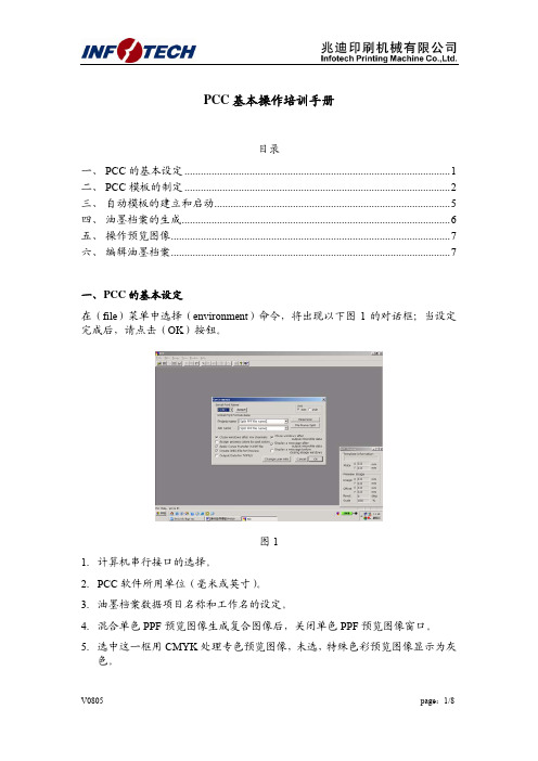
PCC基本操作培训手册目录一、 PCC的基本设定 (1)二、 PCC模板的制定 (2)三、自动模板的建立和启动 (5)四、油墨档案的生成 (6)五、操作预览图像 (7)六、编辑油墨档案 (7)一、P CC的基本设定在(file)菜单中选择(environment)命令,将出现以下图1的对话框;当设定完成后,请点击(OK)按钮。
图11.计算机串行接口的选择。
2.PCC软件所用单位(毫米或英寸)。
3.油墨档案数据项目名称和工作名的设定。
4.混合单色PPF预览图像生成复合图像后,关闭单色PPF预览图像窗口。
5.选中这一框用CMYK处理专色预览图像,未选,特殊色彩预览图像显示为灰色。
6.应用PPF文件确定的校准曲线。
7.生成K-STATION和KMS-IV上显示的预览JPEG文件。
不过,要注意,在油墨档案数据以PQ0格式则不生成JPEG文件。
8.生成TOPILS时(注:东芝轮转机)用。
9.油墨档案数据写入磁卡或将数据存入软盘或硬盘后,关闭窗口。
10.油墨档案数据写入磁卡或将数据存入软盘或硬盘后,显示所存储的完整信息。
11.在关闭预览图像窗口时,显示一条信息,询问是否将图像存储为KVIEW文件。
12.更改用户注册信息。
二、P CC模板的制定模板定义在印刷机上使用印版的尺寸、油墨键开合度和机器编号等参数;请根据模板所用的印刷机定制模板,最多可生成64个模板。
模板生成方法如下:从(file)中选择(template)→(new)将出现以下的图2对话框:点击(OK)按钮存储设置参数即可。
1.选择印刷机类型。
1.1.不带翻转的对开单张印刷机LS系列就选择:Lithrone 40(key 30)1.2.不带翻转的对开单张印刷机L系列就选择:Lithrone 40(key 34)1.3.上下座对开单张印刷机LS系列就选择:Lithrone 40RP(key 30)2.选择油墨键数据格式。
有两种格式:PQ4和PQ03.选择(Normal)、(KHS)或(Original)变换曲线。

第1章 PCC3100控制器介绍 系统概述PCC是康明斯电力系统发电机组上使用的以微处理器为基础的控制器,它提供燃油控制和发动机调速功能、主发电机输出电压调整和全套机组控制和监测。
它同时还提供隔离母排或市电(主用电源)并联电力系统的自动和半自动同步,以及自动负载分配控制功能。
操作软件控制发电机组及其性能特征,并通过数字式显示屏显示机组的运行状态,由前端面板上的按键进行控制或功能设定。
发电机组控制功能 下图显示出一部分控制功能,后面有更完整的方框图。
系统接线图参阅电路图。
PCC 经由磁电式转速传感器(MPU)和主定子的输入获取频率信号,控制盘送出一低功率脉冲宽度调制(PWM)信号到调速器输出模块,然后向发动机燃油控制器输出一个放大信号。
母排电压互感器模块将母排电压降低到大约18 VAC,并向控制盘提供一信号,作为发电机组与系统母排同步的参考信号。
由外部的电压/电流互感器(PT/CT)模块将发电机电压降至18 VAC,并经由电流互感器(CT)输出 电流产 生一个参考交流电压,通过电压调节向调 压器输出模块输出一个低功率PWM信号,然后向励磁机定子输出一个放大信号。
机油、冷却液和排烟温度由可变电阻传感器传送信号,机油压力由电容式传感器传送信号。
电路板和模块概述以下叙述有关PCC控制盘和附件箱内的电路板与模块的功能方框图显示了PCC系统的内部和外部部件。
静电放电将损坏电路板,当接触电路板或接插晶片时,请预先戴好手腕型接地环带。
电路板位置方框图数字电路板(A32)数字电路板包含控制盘用微处理器和操作软件,同时数字电路板还连接到控制盘内其它电路板。
数字电路板也为PCC 提供模拟信号与数字信号之间的转换。
开关S5 将开关推向左侧为接电模式,此时控制盘电源/操作软件一直通电,直到开关扳到备用模式。
建议在所有应用中始终将S5开关设在接电模式位置,除非不能提供辅助蓄电池充电。
向右推动此开关将PCC 切换到备用模式。

Application GuideTable of ContentsChapter 1. Introdution (1)Chapter 2. System Design (2)Chapter 3. Application Architecture (4)Chapter 4. DOCA Libraries (5)Chapter 5. Configuration Flow (6)Chapter 6. Running the Application (8)Chapter 7. Arg Parser DOCA Flags (10)Chapter 8. Port Programmable Congestion Control Register (12)8.1. Usage (12)8.2. Internal Default Algorithm (16)8.3. Counters (16)Chapter 9. References (18)Chapter 1.IntrodutionProgrammable congestion control (PCC) allows users to design and implement their own congestion control (CC) algorithm, giving them good flexibility to work out an optimal solution to handle congestion in their clusters. On BlueField-3, PCC is provided as a component of DOCA.The DOCA PCC application provides users the flexibility to manage allocation of DPA resources according to their needs. The application leverages the DOCA PCC library to generate an executable binary file.Typical DOCA application includes App running on host/Arm and App running on DPA. Developers are advised to use the host/Arm application with minimal changes and focus on developing their algorithm and integrating it into the DPA application.Chapter 2.System DesignDOCA PCC application consists of two parts:‣Host/Arm app is the control plane. It is responsible for allocating all resources and handover to the DPA app initially, then destroying everything when the DPA appfinishes its operation. The host app must always be alive to stay in control while the device app is working.‣Device/DPA app is the data plane. It is mainly for CC event handler. When the first thread is activated, DPA App initialization is done in the DOCA PCC library by calling the algorithm initialization function implemented by the user in the app. Moreover, the user algorithm execution function is called when a CC event arrives. The user algorithm takes event data as input and performs a calculation using per-flowcontext and replies with updated rate value and a flag to sent RTT request.The host/Arm application sends command to NIC firmware when allocating or destroying resources. CC events are generated by NIC hardware automatically when sending data or receiving ACK/NACK/CNP/RTT packets, then the device application handles these eventsSystem Designby calling the user algorithm. After the DPA application replies to hardware, handling of current event is done and the next event can arrive.Chapter 3.Application Architecture/opt/mellanox/doca/applications/pcc/src├── host│ ├── pcc.c│ ├── pcc_core.c│ └── pcc_core.h└── device├── algo│ ├── rtt_template.h│ ├── rtt_template_algo_params.h│ ├── rtt_template_ctxt.h│ └── rtt_template.c└── pcc_dev_main.cThe main content of the reference DOCA PCC application files are the following:‣host/pcc.c – entry point to entire application‣host/pcc_core.c – host functions to initialize and destroy the PCC application resources, parsers for PCC command line parameters‣device/pcc_dev_main.c – callbacks for user CC algorithm initialization, user CC algorithm calculation, algorithm parameter change notification‣device/algo/* – user CC algorithm reference template. Put user algorithm code here.Chapter 4.DOCA LibrariesThis application leverages the following DOCA libraries:‣DOCA PCC libraryChapter 5.Configuration Flow1.Parse application argument.a).Initialize arg parser resources and register DOCA general parameters.doca_argp_init();b).Register PCC application parameters.register_pcc_params();c).Parse all registered parameters.doca_argp_start();i.Parse DOCA flags.ii.Parse DOCA PCC parameters.2.PCC initialization.pcc_init();a).Open DOCA device that supports PCC.b).Create DOCA PCC context.c).Configure affinity of threads handling CC events.3.Start DOCA PCC.doca_pcc_start();a).Create PCC process and other resources.b).Trigger initialization of PCC on device.c).Register the PCC in the NIC hardware so CC events can be generated and anevent handler can be triggered.4.Process state monitor loop.doca_pcc_get_process_state();doca_pcc_wait();a).Get the state of the process:Configuration Flowb).Wait on process events from the device.5.PCC destroy.doca_pcc_destroy();a).Destroy PCC resources. The process stops handling PCC events.b).Close DOCA device.6.Arg parser destroy.doca_argp_destroy();Chapter 6.Running the Application1.Refer to the following documents:‣NVIDIA DOCA Installation Guide for Linux for details on how to install BlueField-related software.‣NVIDIA DOCA Troubleshooting Guide for any issue you may encounter with the installation, compilation, or execution of DOCA applications.‣NVIDIA DOCA Applications Overview for additional compilation instructions and development tips of DOCA applications.2.The pre-built PCC binary is located under /opt/mellanox/doca/applications/pcc/ bin/doca_pcc. To build all the applications together, run:cd /opt/mellanox/doca/applications/meson /tmp/buildninja -C /tmp/build3.To build only the allreduce application:a).Edit the following flags in /opt/mellanox/doca/applications/meson_options.txt:‣Set enable_all_applications to false‣Set enable_pcc to trueb).Run the commands in step 2.Note: doca_pcc is created under /tmp/build/pcc/src/.4.Pre-run setup:a).Enable USER_PROGRAMMABLE_CC in mlxconfig:mlxconfig -y -d /dev/mst/mt41692_pciconf0 set USER_PROGRAMMABLE_CC=1b).Reset firmware or power cycle the host.5.Running the application on the host or BlueField, CLI example:/opt/mellanox/doca/applications/pcc/bin/doca_pcc -d mlx5_0Application usage:Usage: doca_pcc [DOCA Flags] [Program Flags]DOCA Flags:-h, --help Print a help synopsis-v, --version Print program version information-l, --log-level Set the log level for the program <CRITICAL=20, ERROR=30, WARNING=40, INFO=50, DEBUG=60>Running the ApplicationProgram Flags:-d, --device <IB device names> IB device name that supports PCC(mandatory).-w, --wait-time <PCC wait time> The duration of the DOCA PCC wait(optional), can provide negative values which means infinity. If not provided then -1 will be chosen.-p, --pcc-threads <pcc-threads-list> A list of the PCC threads numbers to be chosen for the DOCA PCC context to run on (optional). Must be provided as astring, such that the number are separated by a space.For additional information on available flags, use -h:/opt/mellanox/doca/applications/pcc/bin/doca_pcc -h6.To run doca_pcc using a JSON file:doca_pcc --json [json_file]For example:cd /opt/mellanox/doca/applications/pcc/bin./doca_pcc –-json ./pcc_params.jsonChapter 7.Arg Parser DOCA Flags Refer to NVIDIA DOCA Arg Parser Programming Guide for more information.Arg Parser DOCA FlagsChapter 8.Port ProgrammableCongestion ControlRegisterThe Port Programmable Congestion Control (PPCC) register allows the user to configure and read PCC algorithm parameters.It supports the following functionalities:‣Enabling different algorithms on different ports‣Querying information of both algorithms and tunable parameters/counters‣Changing algorithm parameters without compiling and reburning user image‣Querying or clearing programmable counters8.1. UsageThe PPCC register can be accessed using a string similar to the following:sudo mlxreg -d /dev/mst/mt41692_pciconf0 -y --get --op "cmd_type=0" --reg_name PPCC --indexes "local_port=1,pnat=0,lp_msb=0,algo_slot=0,algo_param_index=0"sudo mlxreg -d /dev/mst/mt41692_pciconf0 -y --set "cmd_type=1" --reg_name PPCC --indexes "local_port=1,pnat=0,lp_msb=0,algo_slot=0,algo_param_index=0"Where you must:‣Set the cmd_type and the indexes‣Give values for algo_slot, algo_param_index‣Keep local_port=1, pnat=0, lp_msb=0‣Keep doca_pcc application running8.2. Internal Default AlgorithmThe internal default algorithm is used when enhanced connection establishment (ECE) negotiation fails. It is mainly used for backward compatibility and can be disabled using "force mode". Otherwise, users may change doca_pcc_dev_user_algo() in the device app to run a specific algorithm without considering the algorithm negotiation.The force mode command is per port:sudo mlxreg -d /dev/mst/mt41692_pciconf0 -y --get --op "cmd_type=2" --reg_name PPCC --indexes "local_port=1,pnat=0,lp_msb=0,algo_slot=15,algo_param_index=0"sudo mlxreg -d /dev/mst/mt41692_pciconf0.1 -y --get --op "cmd_type=2" --reg_name PPCC --indexes "local_port=1,pnat=0,lp_msb=0,algo_slot=15,algo_param_index=0"8.3. CountersCounters are shared on the port and are only enabled on one algo_slot per port. The following command enables the counters while enabling the algorithm according to the algo_slot:sudo mlxreg -d /dev/mst/mt41692_pciconf0 -y --set "cmd_type=1,counter_en=1" --reg_name PPCC --indexes "local_port=1,pnat=0,lp_msb=0,algo_slot=0,algo_param_index=0"After counters are enabled on the algo_slot, they can be queried using cmd_type 0xC or 0xD.sudo mlxreg -d /dev/mst/mt41692_pciconf0 -y --get --op "cmd_type=12" --reg_name PPCC --indexes "local_port=1,pnat=0,lp_msb=0,algo_slot=0,algo_param_index=0"sudo mlxreg -d /dev/mst/mt41692_pciconf0 -y --get --op "cmd_type=13" --reg_name PPCC --indexes "local_port=1,pnat=0,lp_msb=0,algo_slot=0,algo_param_index=0"Chapter 9.References ‣/opt/mellanox/doca/applications/pcc/srcNoticeThis document is provided for information purposes only and shall not be regarded as a warranty of a certain functionality, condition, or quality of a product. NVIDIA Corporation nor any of its direct or indirect subsidiaries and affiliates (collectively: “NVIDIA”) make no representations or warranties, expressed or implied, as to the accuracy or completeness of the information contained in this document and assume no responsibility for any errors contained herein. NVIDIA shall have no liability for the consequences or use of such information or for any infringement of patents or other rights of third parties that may result from its use. This document is not a commitment to develop, release, or deliver any Material (defined below), code, or functionality.NVIDIA reserves the right to make corrections, modifications, enhancements, improvements, and any other changes to this document, at any time without notice.Customer should obtain the latest relevant information before placing orders and should verify that such information is current and complete.NVIDIA products are sold subject to the NVIDIA standard terms and conditions of sale supplied at the time of order acknowledgement, unless otherwise agreed in an individual sales agreement signed by authorized representatives of NVIDIA and customer (“Terms of Sale”). NVIDIA hereby expressly objects to applying any customer general terms and conditions with regards to the purchase of the NVIDIA product referenced in this document. No contractual obligations are formed either directly or indirectly by this document.NVIDIA products are not designed, authorized, or warranted to be suitable for use in medical, military, aircraft, space, or life support equipment, nor in applications where failure or malfunction of the NVIDIA product can reasonably be expected to result in personal injury, death, or property or environmental damage. NVIDIA accepts no liability for inclusion and/or use of NVIDIA products in such equipment or applications and therefore such inclusion and/or use is at customer’s own risk.NVIDIA makes no representation or warranty that products based on this document will be suitable for any specified use. Testing of all parameters of each product is not necessarily performed by NVIDIA. It is customer’s sole responsibility to evaluate and determine the applicability of any information contained in this document, ensure the product is suitable and fit for the application planned by customer, and perform the necessary testing for the application in order to avoid a default of the application or the product. Weaknesses in customer’s product designs may affect the quality and reliability of the NVIDIA product and may result in additional or different conditions and/or requirements beyond those contained in this document. NVIDIA accepts no liability related to any default, damage, costs, or problem which may be based on or attributable to: (i) the use of the NVIDIA product in any manner that is contrary to this document or (ii) customer product designs.No license, either expressed or implied, is granted under any NVIDIA patent right, copyright, or other NVIDIA intellectual property right under this document. Information published by NVIDIA regarding third-party products or services does not constitute a license from NVIDIA to use such products or services or a warranty or endorsement thereof. Use of such information may require a license from a third party under the patents or other intellectual property rights of the third party, or a license from NVIDIA under the patents or other intellectual property rights of NVIDIA.Reproduction of information in this document is permissible only if approved in advance by NVIDIA in writing, reproduced without alteration and in full compliance with all applicable export laws and regulations, and accompanied by all associated conditions, limitations, and notices.THIS DOCUMENT AND ALL NVIDIA DESIGN SPECIFICATIONS, REFERENCE BOARDS, FILES, DRAWINGS, DIAGNOSTICS, LISTS, AND OTHER DOCUMENTS (TOGETHER AND SEPARATELY, “MATERIALS”) ARE BEING PROVIDED “AS IS.” NVIDIA MAKES NO WARRANTIES, EXPRESSED, IMPLIED, STATUTORY, OR OTHERWISE WITH RESPECT TO THE MATERIALS, AND EXPRESSLY DISCLAIMS ALL IMPLIED WARRANTIES OF NONINFRINGEMENT, MERCHANTABILITY, AND FITNESS FOR A PARTICULAR PURPOSE. TO THE EXTENT NOT PROHIBITED BY LAW, IN NO EVENT WILL NVIDIA BE LIABLE FOR ANY DAMAGES, INCLUDING WITHOUT LIMITATION ANY DIRECT, INDIRECT, SPECIAL, INCIDENTAL, PUNITIVE, OR CONSEQUENTIAL DAMAGES, HOWEVER CAUSED AND REGARDLESS OF THE THEORY OF LIABILITY, ARISING OUT OF ANY USE OF THIS DOCUMENT, EVEN IF NVIDIA HAS BEEN ADVISED OF THE POSSIBILITY OF SUCH DAMAGES. Notwithstanding any damages that customer might incur for any reason whatsoever, NVIDIA’s aggregate and cumulative liability towards customer for the products described herein shall be limited in accordance with the Terms of Sale for the product.TrademarksNVIDIA, the NVIDIA logo, and Mellanox are trademarks and/or registered trademarks of Mellanox Technologies Ltd. and/or NVIDIA Corporation in the U.S. and in other countries. The registered trademark Linux® is used pursuant to a sublicense from the Linux Foundation, the exclusive licensee of Linus Torvalds, owner of the mark on a world¬wide basis. Other company and product names may be trademarks of the respective companies with which they are associated.Copyright© 2023 NVIDIA Corporation & affiliates. All rights reserved.NVIDIA Corporation | 2788 San Tomas Expressway, Santa Clara, CA 95051。


第一章概述可编程计算机系列水轮机调速器是我所2001年研发的一代新型水轮机调速器,它充分考虑了PLC和IPC两种机型的优点,充分发挥了可编程计算机控制器(PCC)的技术特点,是总结了长控所双微机调速器和全可编程调速器的经验成果而研制的一类新型调速器。
PCC系列调速器适用于大、中、小型混流、转桨、贯流、冲击式等机组。
是长控所大、中型调速器的推荐方案之一。
1.1 功能和特点1.1.1 本调速器具有如下功能1 频率测量与调节:可测量机组和电网的频率,并实现机组频率的调节和控制。
2 频率跟踪:当跟踪功能投入时,机组频率自动跟踪电网频率,可实现快速自动同期并网。
3 自动调整与分配负荷:机组并入电网,调速器将根据其整定的bp值和电网频差,自动调整机组的出力。
4负荷调整:可接受上位机控制指令,实现发电自动控制功能(A.G.C)。
5 开停机操作:接受中控室或上位机指令,实现开停机操作。
6 手动操作:具有电手动和机械手动操作功能,并可无条件、无扰动实现自动运行与手动操作的相互切换。
7 能采集并显示调速系统的主要参数,如:机组频率、电网频率、导叶开度、调节器输出和调节器的整定参数等。
8 有完善的通讯功能,为电站监控系统设置了标准、可靠的接口,能方便地实现与上位机的通讯。
9 具有频率计的相关试验功能。
10 辅助实验功能:通过操作面板上的功能键和显示屏,可以很方便地完成空载摆动和静态特性测试实验。
1.1.2 本调速器的主要特点1 可靠性问题PCC调速器的电气部分由PCC控制器、操作显示面板、各功能模块等构成,平均无故障时间可达50万小时即57年,因此具有比PLC调速器更高的可靠性。
2 测频问题a 测频通道多PCC调速器有四路测频通道,可以用于①机组PT测频、②机组齿盘测频(两路)、③电网频率测量,因此测频容错能力强。
b 测频精度高由于一般的微机测频都采用1M计数时钟,而B&R2003系列CPU的内部计数时钟10M左右。
Phantom Camera Control操作说明书Vision Research, Inc190 Parish DriveWayne New Jersey 07470Phantom Camera Control software操作说明书首先感谢您购买Phantom高速摄像机,为了方便您的使用,特提供简易中文操作说明书。
使用时请参照Phantom像机英文原厂说明,并以英文原厂说明为准。
英文说明书的获得:安装Phantom控制软件,打开Help菜单,进Contents选项:一、Phantom主机的初次使用与连接在您使用Phantom高速像机时,请参考以下步骤:1.清点产品及配件是否齐全:➢Phantom主机➢镜头➢电源适配器➢多功能线缆➢以太网数据线缆➢计算机➢Phantom软件光盘➢三角架云台➢灯光(如果有配置的话)2.在计算机上安装Phantom软件,安装过程和常用软件相同;3.将像机固定在三角架上,连接供电线缆及以太网线数据线缆;4.安装镜头在需要观察大范围物体运动时往往选择焦距50mm以下的标准镜头或者广角镜头,而拍摄直径在10cm左右的小目标运动时往往选择焦距在50mm以上的微距镜头甚至焦距在200mm以上的长焦镜头,目标直径在毫米级甚至更小时可能需要借助专业的光学放大系统比如显微镜来进行拍摄;5.设置计算机上网络IP地址:对于Windows XP系统,依次进入开始--设置--网络连接--本地连接—属性—TCP/IP协议—使用下面的IP地址:将IP地址设置为100.100.100.1子网掩码设置为255.255.0.0其他均为空白即可;对于Windows Vista或者Windows 7系统,点击开始—连接到—打开网络和共享中心—本地连接—属性—TCP/IPv4—使用下面的IP地址:将IP地址设置为100.100.100.1子网掩码设置为255.255.0.0其他均为空白即可;请注意:高速摄像机通过千兆以太网连接,如果没有设置网络IP,像机与电脑将无法连接。
第一章概述可编程计算机系列水轮机调速器是我所2001年研发的一代新型水轮机调速器,它充分考虑了PLC和IPC两种机型的优点,充分发挥了可编程计算机控制器(PCC)的技术特点,是总结了长控所双微机调速器和全可编程调速器的经验成果而研制的一类新型调速器。
PCC系列调速器适用于大、中、小型混流、转桨、贯流、冲击式等机组。
是长控所大、中型调速器的推荐方案之一。
功能和特点本调速器具有如下功能1 频率测量与调节:可测量机组和电网的频率,并实现机组频率的调节和控制。
2 频率跟踪:当跟踪功能投入时,机组频率自动跟踪电网频率,可实现快速自动同期并网。
3 自动调整与分配负荷:机组并入电网,调速器将根据其整定的bp值和电网频差,自动调整机组的出力。
4负荷调整:可接受上位机控制指令,实现发电自动控制功能()。
5 开停机操作:接受中控室或上位机指令,实现开停机操作。
6 手动操作:具有电手动和机械手动操作功能,并可无条件、无扰动实现自动运行与手动操作的相互切换。
7 能采集并显示调速系统的主要参数,如:机组频率、电网频率、导叶开度、调节器输出和调节器的整定参数等。
8 有完善的通讯功能,为电站监控系统设置了标准、可靠的接口,能方便地实现与上位机的通讯。
9 具有频率计的相关试验功能。
10 辅助实验功能:通过操作面板上的功能键和显示屏,可以很方便地完成空载摆动和静态特性测试实验。
本调速器的主要特点1 可靠性问题PCC调速器的电气部分由PCC控制器、操作显示面板、各功能模块等构成,平均无故障时间可达50万小时即57年,因此具有比PLC调速器更高的可靠性。
2 测频问题a 测频通道多PCC调速器有四路测频通道,可以用于①机组PT测频、②机组齿盘测频(两路)、③电网频率测量,因此测频容错能力强。
b 测频精度高由于一般的微机测频都采用1M计数时钟,而B&R2003系列CPU的内部计数时钟10M左右。
因此,PCC测频精度远比一般的微机测频精度高。
Phantom Camera Control操作说明书Vision Research, Inc190 Parish DriveWayne New Jersey 07470Phantom Camera Control software操作说明书首先感谢您购买Phantom高速摄像机,为了方便您的使用,特提供简易中文操作说明书。
使用时请参照Phantom像机英文原厂说明,并以英文原厂说明为准。
英文说明书的获得:安装Phantom控制软件,打开Help菜单,进Contents选项:一、Phantom主机的初次使用与连接在您使用Phantom高速像机时,请参考以下步骤:1.清点产品及配件是否齐全:➢Phantom主机➢镜头➢电源适配器➢多功能线缆➢以太网数据线缆➢计算机➢Phantom软件光盘➢三角架云台➢灯光(如果有配置的话)2.在计算机上安装Phantom软件,安装过程和常用软件相同;3.将像机固定在三角架上,连接供电线缆及以太网线数据线缆;4.安装镜头在需要观察大范围物体运动时往往选择焦距50mm以下的标准镜头或者广角镜头,而拍摄直径在10cm左右的小目标运动时往往选择焦距在50mm以上的微距镜头甚至焦距在200mm以上的长焦镜头,目标直径在毫米级甚至更小时可能需要借助专业的光学放大系统比如显微镜来进行拍摄;5.设置计算机上网络IP地址:对于Windows XP系统,依次进入开始--设置--网络连接--本地连接—属性—TCP/IP协议—使用下面的IP地址:将IP地址设置为100.100.100.1子网掩码设置为255.255.0.0其他均为空白即可;对于Windows Vista或者Windows 7系统,点击开始—连接到—打开网络和共享中心—本地连接—属性—TCP/IPv4—使用下面的IP地址:将IP地址设置为100.100.100.1子网掩码设置为255.255.0.0其他均为空白即可;请注意:高速摄像机通过千兆以太网连接,如果没有设置网络IP,像机与电脑将无法连接。
6.将以太网线缆连上计算机,像机通电,打开Phantom软件PCC ,软件界面显示“Loading settings from cameras”,这是像机与计算机连接成功。
二、Phantom软件PCC 的使用1. PCC控制Live、Play、Manager像机连接成功后进入PCC主界面,我们可看到软件右上角有三个标签,分别为Live、Play、Manager。
他们的作用分别为拍摄、播放、文件与像机管理。
1.1Manager标签该标签所在页面功能主要是对文件进行管理,对像机进行管理,对像机的内核与各种计量参数进行设置。
上图中可以看到当前连接状态下有一台像机sim_122_1_0(以实际显示的像机编号为准),有一个已存在的视频20090422。
参数设置后续测量时介绍。
如果用户对于这部有兴趣,可自行阅读Phantom像机英文原厂说明或联系我们。
1.2Live标签Live界面是Phantom高速摄像机进行各种参数设置与拍摄的界面,用户的绝大多数操作都在这里进行。
1.2.1 Camera的选择➢初次打开Live标签时,出现界面,此时界面无任何显示。
此时点击右上角Camera下拉框,出现对于连接Phantom像机序列号(本例中系列号为VRI 7585),点击确认后就可以在PCC软件上控制像机。
➢此时Live操作界面各种像机控制参数选项激活1.2.2 各种设置参数的设置➢Camera Settings可在此选项中设置像机图像深度、内存分区。
设置像机的时钟:当前像机显示的时钟current time,如果该时间与电脑的时间不一致,可以点击set time 进行设置,弹出set camera time对话框,根据相应的内容设置好时钟后,点击update and set按钮,current time显示的时间就修改成功。
容量独立分区:根据需要可对像机的内存容量进行分区,每个分区独立进行设置,设置完毕后,当像机接收到触发信号时,将按照1,2...的编号逐步工作,也可在后续的Cine Settings>Cine下拉框中进行选择来操作不同的分区。
➢Cine Settings像机拍摄参数主要在此选项中设置,包含:分区显示(Cine)分辨率(Resolution)拍摄速率(Sample Rate)曝光时间(Exposure)EDR设置(EDR)CSR(当前状态下的黑平衡)触发点设置(Image Range and Trigger Position)状态提示(Duration)请注意:EDR为二次曝光时间设置,用于有效抑制过饱和现象,与后续的自动曝光控制二选其一设置;触发点位置的设置是保证是否能捕捉图像的关键性设置可分为前触发、后触发及任意位置触发。
后触发:内存的记录状态可理解为触发后面保留1张(Last为0),前触发:内存的记录状态可理解为触发后开始保留数据这里值得一提的是,在前触发方式下还可设置延迟(Delay),即像机在收到触发信号后将延迟设定的时间后开始记录,如图:Delay为0.551s从图中也可看出图片总张数为342P,延迟后触发位置为892P,具体设置方法为用鼠标将指示条下边的短竖画线拖动到所需位置。
状态提示:Duration:0.342s(342P)表示为当前状态下的记录时间为0.342s,总图片张数为342P(由于每台设备的配置不一样,具体数字以实际显示为准)。
➢Flash Memory该功能只针对配置有扩展容量CineMag和CineFlash的用户开放当您的设备配置有CineMag或CineFlash时,上述界面将高亮显示相关容量的使用状态信息,当确保您的信息妥善保存后,可点击Erase进行格式化。
在Direct recording to CineMag 前面的方块中打上钩(只有CineMag才能打钩,其它配置不能操作),此时可以直接将数据写入CineMag中,Cine Settings中的Sample Rate最高拍摄速率将根据设定的Resolution而定。
➢Advanced Settings该功能用于像机的各种内置参数设置,用户如果需要使用全部该功能,建议自行阅读Phantom像机英文原厂说明或联系我们,这里主要介绍几个常用的参数设置。
1、Start/End of recording actions:拍摄开始/结束后的动作设置a、Auto Black Reference自动黑平衡,选中后,每次像机记录时都将进行一次黑平衡,建议不用选择,如果需要做黑平衡,可在Cine Settings中点击CSR即可;b、Auto save to CineMag/built-in Flash: 内存容量中的数据全部自动存储到CineMag或内置Flash中(根据像机的配置而定);c、Auto save to HDD/CF card: 自动存储到HDD或CF卡中,在filename中指定存储的文件路径;d、Auto play Video Out: 自动播放设置,可设定播放的次数,是否全段播放,播放的起始位置和播放的张数;e、Restart Recording:重新记录,当内存容量中的数据保存完毕后,像机自动清空内存容量,处于记录状态。
2、External Sync:外部时钟设置像机的时钟可选择为Internal、External、Lock To IRIG三种模式;Internal:内部时钟,可在Camera Settings中设定像机的时钟;External:外部时钟,此时像机不能自己设定拍摄速率,拍摄速率取决于外部时钟的脉冲频率,如外部时钟是1000Hz,那么像机的拍摄速率则为1000帧/秒;Lock To IRIG:IRIG-B码时钟,像机的内部时钟以接收到的IRIG时码为准。
3、Trigger触发信号采用上升沿Rising Edge或下降沿Falling Edge触发方式,可在Filter Time 中设定脉冲沿的有效电平位置4、像机开机后的状态和状态配置设置让像机开机后处于空闲状态Idle,或处于扫描状态Capture;Load Settings: 将*.stg文件写入到像机中,*.stg文件为像机的参数状态配置文件可来自于出厂配置文件(随机附带的安装光盘中,注意一定核对光盘中的*.stg文件是你所操作的像机,如你的像机在LIVE下的CAMERA下的号码是7782,那么光盘中的文件应该是7782.stg),当你的像机处于故障状态时,需要写入光盘中的出厂配置文件;也可来自于你所保存的常用的参数设置;Save Settings: 保存当前状态你的参数配置,后缀名为stg;➢Auto Exposure自动曝光控制,选中此选项后,可设置自动曝光的值level(根据现场情况设定一个最佳值如100),当现场环境的光照度过高时,像机将自动调节曝光时间,避免出现过饱和现象,得到最佳的拍摄效果,与Cine Settings中的EDR设置二选其一。
设定自动曝光的区域设置,在Rectangle中输入Left、Top、Right、Bottom,设置需要自动曝光的区域,点击Full选择当前的全画面作为自动曝光的区域;也可在预览窗口中通过鼠标拖曳来选择自动曝光的区域。
➢Frame Rate Profile在同一拍摄中支持5个拍摄速率,用户可通过“Image#“设置拍摄速率变化临界点,”Rate“设置相应拍摄速率。
➢Image-Based Auto-Trigger基于图像的自动触发功能,需要调节检测的灵敏度、自检的区域和自检的频率,用户在使用过程中需要根据现场实验环境做测试,找到一个最佳的自动触发工作状态,建议用户尽量采用其它的触发方式,便于确保能得到实验结果。
➢Continuous Recording连续记录,用户需建立自动保存的目录、文件名与连续触发状态。
当像机接收到触发信号并记录完毕后,会将内存容量中的数据根据您所设定的起始位置firstIamge及保存的图片张数自动保存到您所建立的文件里。
备注:这种连续记录方式通常用于无人值守的环境模式下,当像机接收到触发信号后,完成自动拍摄,自动存储,自动清空并处于扫描状态,等待下一个新的触发信号。
➢Camera Info像机信息,像机名称(可自行更改)、系列号、IP、各种硬件信息。
1.2.3 Phantom像机拍摄➢在Live界面的右下角,有两个按钮分别是“Capture”、“Trigger”。
➢第一次进入PCC是,“Capture”按钮处于红色状态,“Trigger”按钮处于屏蔽状态,此时像机处于待机状态。
➢点击“Capture”按钮,此时“Capture”按钮变为“Abort Recording”,“Trigger”按钮变绿,像机已处于扫描工作状态(或称为等待触发状态)。