Charge Conjugation Violation in Supernovae and The Neutron Shortage for R-Process Nucelosyn
- 格式:pdf
- 大小:86.72 KB
- 文档页数:4

电气规则检查选项PROTEL DXP2004 DRC 规则英文对照一、Error Reporting 错误报告A:Violations Associated with Buses 有关总线电气错误得各类型(共12项)1bus indices out of range 总线分支索引超出范围2Bus range syntax errors 总线范围得语法错误3Illegal bus range values 非法得总线范围值4Illegal bus definitions 定义得总线非法5Mismatched bus label ordering 总线分支网络标号错误排序6Mismatched bus/wire object on wire/bus 总线/导线错误得连接导线/总线7Mismatched bus widths 总线宽度错误8Mismatched bus section index ordering 总线范围值表达错误9Mismatched electrical types on bus 总线上错误得电气类型10Mismatched generics on bus (first index) 总线范围值得首位错误11Mismatched generics on bus (second index) 总线范围值末位错误12Mixed generics and numeric bus labeling 总线命名规则错误B:Violations Associated ponents 有关元件符号电气错误(共20项) 13ponent Implementations with duplicate pins usage 元件管脚在原理图中重复被使用14ponent Implementations with invalid pin mappings 元件管脚在应用中与PCB封装中得焊盘不符15ponent Implementations with missing pins in sequence 元件管脚得序号出现序号丢失16ponent contaning duplicate sub-parts 元件中出现了重复得子部分17ponent with duplicate Implementations 元件被重复使用18ponent with duplicate pins 元件中有重复得管脚19Duplicate ponent models 一个元件被定义多种重复模型20Duplicate part designators 元件中出现标示号重复得部分21Errors in ponent model parameters 元件模型中出现错误得得参数22Extra pin found in ponent display mode 多余得管脚在元件上显示23Mismatched hidden pin ponent 元件隐藏管脚得连接不匹配24Mismatched pin visibility 管脚得可视性不匹配25Missing ponent model parameters 元件模型参数丢失26Missing ponent models 元件模型丢失27Missing ponent models in model files 元件模型不能在模型文件中找到28Missing pin found in ponent display mode 不见得管脚在元件上显示29Models found in different model locations 元件模型在未知得路径中找到30Sheet symbol with duplicate entries 方框电路图中出现重复得端口31Un-designated parts requiring annotation 未标记得部分需要自动标号32Unused sub-part in ponent 元件中某个部分未使用C:violations associated with document 相关得文档电气错误(共10项) 33conflicting constraints 约束不一致得34duplicate sheet symbol name 层次原理图中使用了重复得方框电路图35duplicate sheet numbers 重复得原理图图纸序号36missing child sheet for sheet symbol 方框图没有对应得子电路图37missing configuration target 缺少配置对象38missing sub-project sheet for ponent 元件丢失子项目39multiple configuration targets 无效得配置对象40multiple top-level document 无效得顶层文件41port not linked to parent sheet symbol 子原理图中得端口没有对应到总原理图上得端口42sheet enter not linked to child sheet 方框电路图上得端口在对应子原理图中没有对应端口D:violations associated with nets 有关网络电气错误(共19项)43adding hidden net to sheet 原理图中出现隐藏网络44adding items from hidden net to net 在隐藏网络中添加对象到已有网络中45auto-assigned ports to device pins 自动分配端口到设备引脚46duplicate nets 原理图中出现重名得网络47floating net labels 原理图中有悬空得网络标签48global power-objects scope changes 全局得电源符号错误49net parameters with no name 网络属性中缺少名称50net parameters with no value 网络属性中缺少赋值51nets containing floating input pins 网络包括悬空得输入引脚52nets with multiple names 同一个网络被附加多个网络名53nets with no driving source 网络中没有驱动54nets with only one pin 网络只连接一个引脚55nets with possible connection problems 网络可能有连接上得错误56signals with multiple drivers 重复得驱动信号57sheets containing duplicate ports 原理图中包含重复得端口58signals with load 信号无负载59signals with drivers 信号无驱动60unconnected objects in net 网络中得元件出现未连接对象61unconnected wires 原理图中有没连接得导线E:Violations associated with others有关原理图得各种类型得错误(3项)62No Error 无错误63Object not pletely within sheet boundaries 原理图中得对象超出了图纸边框64Off-grid object原理图中得对象不在格点位置F:Violations associated with parameters 有关参数错误得各种类型65same parameter containing different types 相同得参数出现在不同得模型中66same parameter containing different values 相同得参数出现了不同得取值二、parator 规则比较A:Differences associated with ponents 原理图与PCB上有关得不同(共16项)67Changed channel class name 通道类名称变化68Changed ponent class name 元件类名称变化69Changed net class name 网络类名称变化70Changed room definitions 区域定义得变化71Changed Rule 设计规则得变化72Channel classes with extra members 通道类出现了多余得成员73ponent classes with extra members 元件类出现了多余得成员74Difference ponent 元件出现不同得描述75Different designators 元件标示得改变76Different library references 出现不同得元件参考库77Different types 出现不同得标准78Different footprints 元件封装得改变79Extra channel classes 多余得通道类80Extra ponent classes 多余得元件类81Extra ponent 多余得元件82Extra room definitions 多余得区域定义B:Differences associated with nets 原理图与PCB上有关网络不同(共6项)83Changed net name 网络名称出现改变84Extra net classes 出现多余得网络类85Extra nets 出现多余得网络86Extra pins in nets 网络中出现多余得管脚87Extra rules 网络中出现多余得设计规则88Net class with Extra members 网络中出现多余得成员C:Differences associated with parameters 原理图与PCB上有关得参数不同(共3项)89Changed parameter types 改变参数类型90Changed parameter value 改变参数得取值91Object with extra parameter 对象出现多余得参数【Violations Associated with Buses】栏——总线电气错误类型(1)【Bus indices out of range】:总线分支索引超出范围。


C++出错提示英汉对照表Ambiguous operators need parentheses -----------不明确的运算需要用括号括起Ambiguous symbol ''xxx'' ----------------不明确的符号Argument list syntax error ----------------参数表语法错误Array bounds missing ------------------丢失数组界限符Array size toolarge -----------------数组尺寸太大Bad character in paramenters ------------------参数中有不适当的字符Bad file name format in include directive --------------------包含命令中文件名格式不正确Bad ifdef directive synatax ------------------------------编译预处理ifdef有语法错Bad undef directive syntax ---------------------------编译预处理undef有语法错Bit field too large ----------------位字段太长Call of non-function -----------------调用未定义的函数Call to function with no prototype ---------------调用函数时没有函数的说明Cannot modify a const object ---------------不允许修改常量对象Case outside of switch ----------------漏掉了case 语句Case syntax error ------------------ Case 语法错误Code has no effect -----------------代码不可述不可能执行到Compound statement missing{ --------------------分程序漏掉"{"Conflicting type modifiers ------------------不明确的类型说明符Constant expression required ----------------要求常量表达式Constant out of range in comparison -----------------在比较中常量超出范围Conversion may lose significant digits -----------------转换时会丢失意义的数字Conversion of near pointer not allowed -----------------不允许转换近指针Could not find file ''xxx'' -----------------------找不到XXX文件Declaration missing ; ----------------说明缺少";"Declaration syntax error -----------------说明中出现语法错误Default outside of switch ------------------ Default 出现在switch语句之外Define directive needs an identifier ------------------定义编译预处理需要标识符Division by zero ------------------用零作除数Do statement must have while ------------------ Do-while语句中缺少while部分Enum syntax error ---------------------枚举类型语法错误Enumeration constant syntax error -----------------枚举常数语法错误Error directive :xxx ------------------------错误的编译预处理命令Error writing output file ---------------------写输出文件错误Expression syntax error -----------------------表达式语法错误Extra parameter in call ------------------------调用时出现多余错误File name too long ----------------文件名太长Function call missing -----------------函数调用缺少右括号Fuction definition out of place ------------------函数定义位置错误Fuction should return a value ------------------函数必需返回一个值Goto statement missing label ------------------ Goto语句没有标号Hexadecimal or octal constant too large ------------------16进制或8进制常数太大Illegal character ''x'' ------------------非法字符xIllegal initialization ------------------非法的初始化Illegal octal digit ------------------非法的8进制数字Illegal pointer subtraction ------------------非法的指针相减Illegal structure operation ------------------非法的结构体操作Illegal use of floating point -----------------非法的浮点运算Illegal use of pointer --------------------指针使用非法Improper use of a typedefsymbol ----------------类型定义符号使用不恰当In-line assembly not allowed -----------------不允许使用行间汇编Incompatible storage class -----------------存储类别不相容Incompatible type conversion --------------------不相容的类型转换Incorrect number format -----------------------错误的数据格式Incorrect use of default --------------------- Default使用不当Invalid indirection ---------------------无效的间接运算Invalid pointer addition ------------------指针相加无效Irreducible expression tree -----------------------无法执行的表达式运算Lvalue required ---------------------------需要逻辑值0或非0值Macro argument syntax error -------------------宏参数语法错误Macro expansion too long ----------------------宏的扩展以后太长Mismatched number of parameters in definition ---------------------定义中参数个数不匹配Misplaced break ---------------------此处不应出现break语句Misplaced continue ------------------------此处不应出现continue语句Misplaced decimal point --------------------此处不应出现小数点Misplaced elif directive --------------------不应编译预处理elifMisplaced else ----------------------此处不应出现elseMisplaced else directive ------------------此处不应出现编译预处理elseMisplaced endif directive -------------------此处不应出现编译预处理endifMust be addressable ----------------------必须是可以编址的Must take address of memory location ------------------必须存储定位的地址No declaration for function ''xxx'' -------------------没有函数xxx的说明No stack ---------------缺少堆栈No type information ------------------没有类型信息Non-portable pointer assignment --------------------不可移动的指针(地址常数)赋值Non-portable pointer comparison --------------------不可移动的指针(地址常数)比较Non-portable pointer conversion ----------------------不可移动的指针(地址常数)转换Not a valid expression format type ---------------------不合法的表达式格式Not an allowed type ---------------------不允许使用的类型Numeric constant too large -------------------数值常太大Out of memory -------------------内存不够用Parameter ''xxx'' is never used ------------------能数xxx没有用到Pointer required on left side of -> -----------------------符号->的左边必须是指针Possible use of ''xxx'' before definition -------------------在定义之前就使用了xxx(警告)Possibly incorrect assignment ----------------赋值可能不正确Redeclaration of ''xxx'' -------------------重复定义了xxxRedefinition of ''xxx'' is not identical ------------------- xxx的两次定义不一致Register allocation failure ------------------寄存器定址失败Repeat count needs an lvalue ------------------重复计数需要逻辑值Size of structure or array not known ------------------结构体或数给大小不确定Statement missing ; ------------------语句后缺少";"Structure or union syntax error --------------结构体或联合体语法错误Structure size too large ----------------结构体尺寸太大Sub scripting missing ] ----------------下标缺少右方括号Superfluous & with function or array ------------------函数或数组中有多余的"&" Suspicious pointer conversion ---------------------可疑的指针转换Symbol limit exceeded ---------------符号超限Too few parameters in call -----------------函数调用时的实参少于函数的参数不Too many default cases ------------------- Default太多(switch语句中一个)Too many error or warning messages --------------------错误或警告信息太多Too many type in declaration -----------------说明中类型太多Too much auto memory in function -----------------函数用到的局部存储太多Too much global data defined in file ------------------文件中全局数据太多Two consecutive dots -----------------两个连续的句点Type mismatch in parameter xxx ----------------参数xxx类型不匹配Type mismatch in redeclaration of ''xxx'' ---------------- xxx重定义的类型不匹配Unable to create output file ''xxx'' ----------------无法建立输出文件xxxUnable to open include file ''xxx'' ---------------无法打开被包含的文件xxxUnable to open input file ''xxx'' ----------------无法打开输入文件xxxUndefined label ''xxx'' -------------------没有定义的标号xxxUndefined structure ''xxx'' -----------------没有定义的结构xxxUndefined symbol ''xxx'' -----------------没有定义的符号xxxUnexpected end of file in comment started on line xxx ----------从xxx行开始的注解尚未结束文件不能结束Unexpected end of file in conditional started on line xxx ----从xxx 开始的条件语句尚未结束文件不能结束Unknown assemble instruction ----------------未知的汇编结构Unknown option ---------------未知的操作Unknown preprocessor directive: ''xxx'' -----------------不认识的预处理命令xxx Unreachable code ------------------无路可达的代码Unterminated string or character constant -----------------字符串缺少引号User break ----------------用户强行中断了程序Void functions may not return a value ----------------- Void类型的函数不应有返回值Wrong number of arguments -----------------调用函数的参数数目错''xxx'' not an argument ----------------- xxx不是参数''xxx'' not part of structure -------------------- xxx不是结构体的一部分xxx statement missing ( -------------------- xxx语句缺少左括号xxx statement missing ) ------------------ xxx语句缺少右括号xxx statement missing ; -------------------- xxx缺少分号xxx'' declared but never used -------------------说明了xxx但没有使用xxx'' is assigned a value which is never used ----------------------给xxx赋了值但未用过Zero length structure ------------------结构体的长度为零。
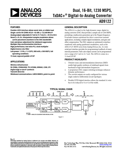
Dual, 16-Bit, 1230 MSPS,TxDAC+® Digital-to-Analog ConverterAD9122 Rev. AInformation furnished by Analresponsibility is assumed by Ana rights of third parties that may re license is granted by implication T rademarks and registered trad MA 02062-9106, U.S.A. Inc. All rights reserved.og Devices is believed to be accurate and reliable. However, nolog Devices for its use, nor for any infringements of patents or other sult from its use. Specifications subject to change without notice. No or otherwise under any patent or patent rights of Analog Devices. emarks are the property of their respective owners. One Technology Way, P.O. Box 9106, Norwood, Tel: 781.329.4700Fax: 781.461.3113 ©2010 Analog Devices,FEATURESFlexible LVDS interface allows word, byte, or nibble load Single-carrier W-CDMA ACLR = 82 dBc @ 122.88 MHz IF Analog output: adjustable 8.7 mA to 31.7 mA, R L = 25 Ω to 50 Ω Novel 2×/4×/8× interpolator/complex modulator allows carrier placement anywhere in the DAC bandwidthGain and phase adjustment for sideband suppression Multiple chip synchronization interfacesHigh performance, low noise PLL clock multiplierDigital inverse sinc filterLow power: 1.5 W @ 1.2 GSPS, 800 mW @ 500 MSPS, full operating conditions72-lead, exposed paddle LFCSPAPPLICATIONSWireless infrastructureW-CDMA, CDMA2000, TD-SCDMA, WiMAX, GSM, LTEDigital high or low IF synthesisTransmit diversityWideband communications: LMDS/MMDS, point-to-point GENERAL DESCRIPTIONThe AD9122 is a dual 16-bit, high dynamic range, digital-to-analog converter (DAC) that provides a sample rate of 1200 MSPS, permitting a multicarrier generation up to the Nyquist frequency. It includes features optimized for direct conversion transmit applications, including complex digital modulation, and gain and offset compensation. The DAC outputs are optimized to interface seamlessly with analog quadrature modulators, such as the ADL537x F-MOD series from Analog Devices, Inc. A 4-wire serial port interface provides for programming/readback of many internal parameters. Full-scale output current can be programmed over a range of 8.7 mA to 31.7 mA. The AD9122 comes in a 72-lead LFCSP.PRODUCT HIGHLIGHTS1.Ultralow noise and intermodulation distortion (IMD)enable high quality synthesis of wideband signals frombaseband to high intermediate frequencies.2. A proprietary DAC output switching technique enhancesdynamic performance.3.The current outputs are easily configured for varioussingle-ended or differential circuit topologies.4.Flexible LVDS digital interface allows the standard 32-wirebus to be reduced to ½ or ¼ of the width.TYPICAL SIGNAL CHAINCOMPLEX BASEBANDDC COMPLEX IFf IFRFLO – f IF8281-1 Figure 1.AD9122Rev. A | Page 2 of 60TABLE OF CONTENTSFeatures .............................................................................................. 1 Applications ....................................................................................... 1 General Description ......................................................................... 1 Product Highlights ........................................................................... 1 Typical Signal Chain ......................................................................... 1 Revision History ............................................................................... 3 Functional Block Diagram .............................................................. 4 Specifications ..................................................................................... 5 DC Specifications ......................................................................... 5 Digital Specifications ................................................................... 6 Digital Input Data Timing Specifications ................................. 6 AC Specifications .......................................................................... 7 Absolute Maximum Ratings ............................................................ 8 Thermal Resistance ...................................................................... 8 ESD Caution .................................................................................. 8 Pin Configuration and Function Descriptions ............................. 9 Typical Performance Characteristics ........................................... 11 Terminology .................................................................................... 17 Differences Between the AD9122R1 and AD9122R2 ............... 18 Theory of Operation ...................................................................... 19 Serial Port Operation ................................................................. 19 Data Format ................................................................................ 19 Serial Port Pin Descriptions ...................................................... 19 Serial Port Options ..................................................................... 20 Device Configuration Register Map and Descriptions ......... 21 LVDS Input Data Ports .................................................................. 33 Word Interface Mode ................................................................. 33 Byte Interface Mode ................................................................... 33 Nibble Interface Mode ............................................................... 33 FIFO Operation .......................................................................... 33 Interface Timing ......................................................................... 35 Digital Datapath .............................................................................. 37 Premodulation ............................................................................ 37 Interpolation Filters ................................................................... 37 NCO Modulation ....................................................................... 40 Datapath Configuration ............................................................ 40 Determining Interpolation Filter Modes ................................ 41 Datapath Configuration Example ............................................ 42 Data Rates vs. Interpolation Modes ......................................... 43 Coarse Modulation Mixing Sequences .................................... 43 Quadrature Phase Correction ................................................... 44 DC Offset Correction ................................................................ 44 Inverse Sinc Filter ....................................................................... 44 DAC Input Clock Configurations ................................................ 45 DAC Input Clock Configurations ............................................ 45 Analog Outputs............................................................................... 47 Transmit DAC Operation .......................................................... 47 Auxiliary DAC Operation ......................................................... 48 Baseband Filter Implementation .............................................. 49 Driving the ADL5375-15 .......................................................... 49 Reducing LO Leakage and Unwanted Sidebands .................. 50 Device Power Dissipation .............................................................. 51 Temperature Sensor ................................................................... 52 Multichip Synchronization ............................................................ 53 Synchronization with Clock Multiplication ............................... 53 Synchronization with Direct Clocking .................................... 54 Data Rate Mode Synchronization ............................................ 54 FIFO Rate Mode Synchronization ........................................... 55 Additional Synchronization Features ...................................... 55 Interrupt Request Operation ........................................................ 57 Interrupt Service Routine .......................................................... 57 Interface Timing Validation .......................................................... 58 SED Operation ............................................................................ 58 SED Example .............................................................................. 58 Example Start-Up Routine ........................................................ 59 Outline Dimensions ....................................................................... 60 Ordering Guide .. (60)AD9122Rev. A | Page 3 of 60REVISION HISTORY3/10—Rev. 0 to Rev. AChanges to Reflect Differences Between R1 and R2Silicon................................................................................... Universal Changes to Features Section ............................................................ 1 Changes to Table 1 ............................................................................ 5 Changes to Table 2 ............................................................................ 6 Changes to Table 5 ............................................................................ 7 Change to IOVDD Rating in Table 6 .............................................. 8 Changes to Table 8 ............................................................................ 9 Changes to Figure 10 to Figure 15 ................................................ 12 Added Differences Between the AD9122R1 and AD9122R2 Section, Added Figure 36 and Figure 37; RenumberedSequentially ...................................................................................... 18 Changes to Table 10 ........................................................................ 21 Changes to Table 11 ........................................................................ 23 Changes to FIFO Operation Section ............................................ 33 Changes to Resettling the FIFO Section and Replaced Table 13; Renumbered Sequentially; Added Serial Port Initiated FIFO Reset Section, and Added FRAME Initiated Relative FIFOReset Section .................................................................................... 34 Added FRAME Initiated Absolute FIFO Reset Section andReplaced Table 14 ............................................................................ 35 Changes to Figure 54 ...................................................................... 38 Changes to Table 18 ........................................................................ 39 Changes to SED Example Section ................................................. 58 Added Example Start-Up Routine Section .................................. 59 9/09—Revision 0: Initial VersionAD9122Rev. A | Page 4 of 60FUNCTIONAL BLOCK DIAGRAMD15P—D15ND0P—D0NIOUT1P IOUT1NIOUT2P IOUT2NFSADJREFIO DCI FRAME08281-002Figure 2. AD9122 Functional Block DiagramAD9122Rev. A | Page 5 of 60SPECIFICATIONSDC SPECIFICATIONST MIN to T MAX , AVDD33 = 3.3 V , DVDD18 = 1.8 V , CVDD18 =1.8 V , I OUTFS = 20 mA, maximum sample rate, unless otherwise noted. Table 1.Parameter Min Typ Max Unit RESOLUTION 16 Bits ACCURACY Differential Nonlinearity (DNL) ±2.1 LSB Integral Nonlinearity (INL) ±3.7 LSB MAIN DAC OUTPUTS Offset Error −0.001 0 +0.001 % FSR Gain Error (with Internal Reference) −3.6 ±2 +3.6 % FSR Full-Scale Output Current 18.66 19.6 31.66 mA Output Compliance Range −1.0 +1.0 V Output Resistance 10 MΩ Gain DAC Monotonicity Guaranteed Settling Time to Within ±0.5 LSB 20 ns MAIN DAC TEMPERATURE DRIFT Offset 0.04 ppm/°C Gain 100 ppm/°C Reference Voltage 30 ppm/°C REFERENCE Internal Reference Voltage 1.2 V Output Resistance 5 kΩ ANALOG SUPPLY VOLTAGES AVDD33 3.13 3.3 3.47 V CVDD18 1.71 1.8 1.89 V DIGITAL SUPPLY VOLTAGES DVDD18 1.71 1.8 1.89 V IOVDD 1.71 1.8/3.3 3.47 V POWER CONSUMPTION 2× Mode, f DAC = 491.22 MSPS, IF = 10 MHz, PLL Off 834 mW 2× Mode, f DAC = 491.22 MSPS, IF = 10 MHz, PLL On 913 mW 8× Mode, f DAC = 800 MSPS, IF = 10 MHz, PLL Off 1135 1241 mWAVDD33 55 57 mA CVDD18 85 90 mA DVDD18 444 495 mA Power-Down Mode (Register 0x01 = 0xF1) 6.5 18.8 mW Power Supply Rejection Ratio, AVDD33 −0.3 +0.3 % FSR/V OPERATING RANGE −40 +25 +85 °C1Based on a 10 kΩ external resistor.AD9122Rev. A | Page 6 of 60DIGITAL SPECIFICATIONST MIN to T MAX , AVDD33 = 1.8 V , IOVDD = 3.3 V , DVDD18 = 1.8 V , CVDD18 = 1.8 V , I OUTFS = 20 mA, maximum sample rate, unless otherwise noted.1LVDS receiver is compliant to the IEEE 1596 reduced range link, unless otherwise noted.DIGITAL INPUT DATA TIMING SPECIFICATIONSTable 3.Parameter Min Typ Max UnitLATENCY (DACCLK Cycles) 1× Interpolation (With or Without Modulation) 64 Cycles 2× Interpolation (With or Without Modulation) 135 Cycles 4× Interpolation (With or Without Modulation) 292 Cycles 8× Interpolation (With or Without Modulation) 608 Cycles Inverse Sinc 20 Cycles Fine Modulation 8 Cycles Power-Up Time 260 msAD9122Rev. A | Page 7 of 60AC SPECIFICATIONST MIN to T MAX , AVDD33 = 3.3 V , DVDD18 = 1.8 V , CVDD18 = 1.8 V , I OUTFS = 20 mA, maximum sample rate, unless otherwise noted. Table 4.ParameterMin Typ Max UnitSPURIOUS-FREE DYNAMIC RANGE (SFDR) f DAC = 100 MSPS, f OUT = 20 MHz 78 dBc f DAC = 200 MSPS, f OUT = 50 MHz 80 dBc f DAC = 400 MSPS, f OUT = 70 MHz 69 dBc f DAC = 800 MSPS, f OUT = 70 MHz72 dBc TWO-TONE INTERMODULATION DISTORTION (IMD) f DAC = 200 MSPS, f OUT = 50 MHz 84 dBc f DAC = 400 MSPS, f OUT = 60 MHz 86 dBc f DAC = 400 MSPS, f OUT = 80 MHz 84 dBc f DAC = 800 MSPS, f OUT = 100 MHz81 dBc NOISE SPECTRAL DENSITY (NSD) EIGHT-TONE, 500 kHz TONE SPACING f DAC = 200 MSPS, f OUT = 80 MHz −162 dBm/Hz f DAC = 400 MSPS, f OUT = 80 MHz −163 dBm/Hz f DAC = 800 MSPS, f OUT = 80 MHz−164 dBm/Hz W-CDMA ADJACENT CHANNEL LEAKAGE RATIO (ACLR), SINGLE CARRIER f DAC = 491.52 MSPS, f OUT = 10 MHz 84 dBc f DAC = 491.52 MSPS, f OUT = 122.88 MHz 82 dBc f DAC = 983.04 MSPS, f OUT = 122.88 MHz 83 dBc W-CDMA SECOND ACLR, SINGLE CARRIER f DAC = 491.52 MSPS, f OUT = 10 MHz 88 dBc f DAC = 491.52 MSPS, f OUT = 122.88 MHz 86 dBc f DAC = 983.04 MSPS, f OUT = 122.88 MHz88dBcTable 5. Interface SpeedsBus Width Interpolation Factorf BUS (Mbps)1.8 V ± 5% 1.8 V ± 2% 1.9 V ± 5% Nibble (4 Bits) 1×1100 1200 1230 2× (HB1) 1100 1200 1230 2× (HB2) 1100 1200 1230 4× 1100 1200 1230 8× 1100 1200 1230 Byte (8 Bits) 1×1100 1200 1230 2× (HB1) 1100 1200 1230 2× (HB2) 1100 1200 1230 4× 1100 1200 1230 8× 550 600 615 Word (16 Bits) 1×1100 1200 1230 2× (HB1) 900 1000 1000 2× (HB2) 1100 1200 1230 4× 550 600 615 8×275 300 307.5AD9122Rev. A | Page 8 of 60ABSOLUTE MAXIMUM RATINGSTHERMAL RESISTANCEThe exposed paddle (EPAD) must be soldered to the ground plane for the 72-lead, LFCSP . The EPAD performs as an electrical and thermal connection to the board.Typical θJA , θJB , and θJC are specified for a 4-layer board in still air. Airflow increases heat dissipation effectively reducing θJA and θJB . Table 7. Thermal ResistancePackage θJA θJB θJC Unit Conditions 72-Lead LFCSP_VQ 20.7 10.9 1.1 °C/W EPAD solderedESD CAUTIONStresses above those listed under Absolute Maximum Ratings may cause permanent damage to the device. This is a stress rating only; functional operation of the device at these or any other conditions above those indicated in the operationalsection of this specification is not implied. Exposure to absolute maximum rating conditions for extended periods may affect device reliability.AD9122Rev. A | Page 9 of 6008281-003D 11P D 11N D 10P D 10N D 9P D 9N D 8P D 8N D C I D C I D V D D 18D V S D 7P D 7N D 6P D 6N D 5P D 5N PIN CONFIGURATION AND FUNCTION DESCRIPTIONS12345678910111213141516CVDD18DACCLKP DACCLKNCVSS FRAMEP FRAMENIRQ D15P D15N NC IOVDD DVDD18D14P D14N D13P D13N 17D12P 18D12N 19202122232425262728293031323334P N S 3536545352515049484746454443424140393837RESET CS SCLK SDIO SDO DVDD18D0N D0P D1N D1P DVSS DVDD18D2N D2P D3N D3P D4N D4P727170696867666564636261605958575655C VD D 18C V D D 18REF C L K P R E F C L K N A V D D 33I O U T 1P I O U T 1N A V D D 33A V S S F S A D J R E F I O A V S S A V D D 33I O U T 2N I O U T 2P A V D D 33A V S S NCNOTES1. NC = NO CONNECT.2. EXPOSED PAD MUST BE CONNECTED TO AVSS.Figure 3. Pin ConfigurationAD9122Rev. A | Page 10 of 60AD9122050100150200250300350400450f OUT (MHz)TYPICAL PERFORMANCE CHARACTERISTICS0–10–20–30–40–50–60–70–80–90–100H A R M O N I C S (d B c)08281-10150100150200250300350400450f OUT (MHz)Figure 4. Harmonics vs. f OUT over f DATA , 2× Interpolation,Digital Scale = 0 dBFS, f SC = 20 mA0–10–20–30–40–50–60–70–80–90–100H A R M O N I C S (d B c )08281-10208281-1030–10–20–30–40–50–60–70–80–90–100050100150200250300350400450H A R M O N I C S (d B c )f OUT(MHz)08281-1040–10–20–30–40–50–60–70–80–90–10050100150200250300350400450H A R M O N I C S (d B c )f OUT (MHz)Figure 7. Second Harmonic vs. f OUT over Digital Scale, 2× Interpolation,f DATA = 400 MSPS, f SC= 20 mA08281-1050–10–20–30–40–50–60–70–80–90–10050100150200250300350400450H A R M O N I C S (d B c )f OUT (MHz)Figure 5. Harmonics vs. f OUT over f DATA , 4× Interpolation,Digital Scale = 0 dBFS, f SC = 20 mAFigure 8. Third Harmonic vs. f OUT over Digital Scale, 2× Interpolation,f DATA = 400 MSPS, f SC = 20 mA0–10–20–30–40–50–60–70–80–90–100H A R M O N I C S (d B c )100200300400500600700f OUT (MHz)08281-106Figure 6. Harmonics vs. f OUT over f DATA , 8× Interpolation,Digital Scale = 0 dBFS, f SC = 20 mA Figure 9. Second Harmonic vs. f OUT over f SC , 2× Interpolation,f DATA = 400 MSPS, Digital Scale = 0 dBFSAD9122–69–70–71–72–73–74–75–77H I G H E S T D I G I T A L S P U R (d B c )–78–79050100150200250300350400450f OUT (MHz)–7608281-10708281-110START 1.0MHz #RES BW 10kHzVBW 10kHzSTOP 500.0MHzSWEEP 6.017s (601 PTS)08281-111START 1.0MHz #RES BW 10kHzVBW 10kHzSTOP 800.0MHzSWEEP 9.634s (601 PTS)Figure 10. Highest Digital Spur vs. f OUT over f DATA , 2× Interpolation,Digital Scale = 0 dBFS, f SC = 20 mA–60–65–70–75–80–85H I G H E S T D I G I T A L S P U R (d B c )050100150200250300350400450f OUT (MHz)08281-108Figure 11. Highest Digital Spur vs. f OUT over f DATA , 4× Interpolation,Digital Scale = 0 dBFS, f SC = 20 mA–60–90–95–85–80–75–70–65H I G H E S T D I G I T A L S P U R (d B c )010*******400500600700f OUT (MHz)08281-109Figure 12. Highest Digital Spur vs. f OUT over f DATA , 8× Interpolation,Digital Scale = 0 dBFS, f SC = 20 mAFigure 13. 2× Interpolation, Single-Tone Spectrum, f DATA = 250 MSPS,f OUT= 101 MHzFigure 14. 4× Interpolation, Single-Tone Spectrum, f DATA = 200 MSPS,f OUT = 151 MHz08281-START 1.0MHz #RES BW 10kHzVBW 10kHzSTOP 800.0MHzSWEEP 9.634s (601 PTS)112Figure 15. 8× Interpolation, Single-Tone Spectrum, f DATA = 100 MSPS,f OUT = 131 MHzAD91220–90–80–70–60–50–40–30–20–10I M D (d B c )050100150200250300350400450f OUT (MHz)308281-11Figure 16. IMD vs. f OUT over f DATA , 2× Interpolation,Digital Scale = 0 dBFS, f SC = 20 mA0–80–70–60–50–40–30–20–10–90I M D (d B c )050100150200250300350400450f OUT (MHz)408281-11Figure 17. IMD vs. f OUT over f DATA , 4× Interpolation,Digital Scale = 0 dBFS, f SC = 20 mA0–80–70–60–50–40–30–20–10I M D (d B c )–100–90050100150200250300350400450f OUT(MHz)08281-115Figure 18. IMD vs. f OUT over f DATA , 8× Interpolation,Digital Scale = 0 dBFS, f SC = 20 mA0–90–80–70–60–50–40–30–20–10050100150200250300350400450I M D (d B c )f OUT(MHz)08281-116Figure 19. IMD vs. f OUT over Digital Scale, 2× Interpolation,f DATA = 400 MSPS, f SC = 20 mA–50–85–80–75–70–65–60–55050100150200250300350400450I M D (d B c )f OUT (MHz)08281-117Figure 20. IMD vs. f OUT over f SC , 2× Interpolation, f DATA = 400 MSPS,Digital Scale = 0 dBFS–40–90–85–80–75–70–65–60–55–50–45I M D (d B c)050100150200250300350400450f OUT (MHz)08281-118Figure 21. IMD vs. f OUT , PLL On vs. PLL Off, 4× Interpolation, f DATA = 200 MSPS,Digital Scale = 0 dBFS, f SC = 20 mAAD9122–152–156–154–158–160–162–164––166N S D (d B m /H z )50100150200250300350400450f OUT (MHz)908281-11Figure 22. 1-Tone NSD vs. f OUT over Interpolation Rate, Digital Scale = 0 dBFS,f SC = 20 mA, PLL Off–154–158–156–160–162–164–166–168N S D (d B m /H z )050100150200250300350400450f OUT (MHz)08281-12Figure 23. 1-Tone NSD vs. f OUT over Digital Scale, f DATA = 200 MSPS,4× Interpolation, f SC = 20 mA, PLL Off–158–159–160–161–162–163–164–165N S D (d B m /H z )–166050100150200250300350400450f OUT (MHz)08281-121Figure 24. 1-Tone NSD vs. f OUT over Interpolation Rate, Digital Scale = 0 dBFS,f SC = 20 mA, PLL On 161.0–165.5–165.0–164.5–164.0–163.5–163.0–162.5–162.0–161.5050100150200250300350400450N S D (d B m /H z )f OUT(MHz)08281-122Figure 25. 8-Tone NSD vs. f OUT over Interpolation Rate, Digital Scale = 0 dBFS,f SC = 20 mA, PLL Off–161.0–166.5–165.5–166.0–165.0–164.5–164.0–163.5–163.0–162.5–162.0–161.5050100150200250300350400450N S D (d B m /H z )fOUT (MHz)08281-123Figure 26. 8-Tone NSD vs. f OUT over Digital Scale, f DATA = 200 MSPS,4× Interpolation, f SC = 20 mA, PLL Off–160–161–162–163–164–165–166N S D (d B m /H z)050100150200250300350400450f OUT (MHz)08281-124Figure 27. 8-Tone NSD vs. f OUT over Interpolation Rate, Digital Scale = 0 dBFS,f SC = 20 mA, PLL OnAD9122–77–84–83–82–81–80–79–78A C L R (d B c )–050100150200250fOUT (MHz)50–55–60–65–70–75–80–85–900100200300400500A C L R (dB c )f OUT(MHz)08281-12508281-128Figure 28. 1-Carrier W-CDMA ACLR vs. f OUT over Digital Scale,Adjacent Channel, PLL Off–78–88–86–84–82–80–90A C L R (dB c )050100150200250fOUT (MHz)08281-126Figure 29. 1-Carrier W-CDMA ACLR vs. f OUT over f DAC ,Alternate Channel, PLL Off–70–90–85–80–75A C L R (dB c )–95050100150200250fOUT (MHz)08281-127Figure 30. 1-Carrier W-CDMA ACLR vs. f OUT over f DAC ,Second Alternate Channel, PLL Off Figure 31. 1-Carrier W-CDMA ACLR vs. f OUT , Adjacent Channel,PLL On vs. PLL Off–70–72–74–76–78–80–82–84–86–88–900100200300400500A C L R (dB c )f OUT(MHz)08281-129Figure 32. 1-Carrier W-CDMA ACLR vs. f OUT , Alternate Channel,PLL On vs. PLL Off–70–95–90–85–80–75A C L R (dB c)0100200300400500f OUT (MHz)08281-130Figure 33. 1-Carrier W-CDMA ACLR vs. f OUT , Second Alternate Channel,PLL On vs. PLL OffAD912208281-131START 133.06MHz #RES BW 30kHzVBW 30kHz STOP 166.94MHzSWEEP 143.6ms (601 PTS)START 125.88MHz #RES BW 30kHz VBW 30kHz STOP 174.42MHzSWEEP 206.9ms (601 PTS)TOTAL CARRIER POWER –11.19dBm/15.3600MHz RRC FILTER: OFF FILTER ALPHA 0.22REF CARRIER POWER –16.89dBm/3.84000MHzLOWER UPPER OFFSET FREQ INTEG BW dBc dBm dBc dBm 1–16.92dBm 5.000MHz 3.840MHz –65.88–82.76–67.52–84.40RMS RESULTS FREQ LOWER UPPER OFFSET REF BW dBc dBm dBc dBm CARRIER POWER 5.00MHz 3.840MHz –75.96–85.96–77.13–87.13–10.00dBm/10.00MHz 3.840MHz –85.33–95.33–85.24–95.253.840MHz15.00MHz2.888MHz–95.81–95.81–85.43–95.4308281-1322–16.89dBm 10.00MHz 3.840MHz –68.17–85.05–69.91–86.793–17.43dBm 15.00MHz 3.840MHz–70.42–87.31–71.40–88.284–17.64dBmFigure 35. 1-Carrier W-CDMA ACLR Performance, IF = ~150 MHzFigure 34. 4-Carrier W-CDMA ACLR Performance, IF = ~150 MHzAD9122 TERMINOLOGYIntegral Nonlinearity (INL)INL is defined as the maximum deviation of the actual analog output from the ideal output, determined by a straight line drawn from zero scale to full scale.Differential Nonlinearity (DNL)DNL is the measure of the variation in analog value, normalized to full scale, associated with a 1 LSB change in digital input code. Offset ErrorThe deviation of the output current from the ideal of zero is called offset error. For IOUT1P, 0 mA output is expected when the inputs are all 0s. For IOUT1N, 0 mA output is expected when all inputs are set to 1.Gain ErrorThe difference between the actual and ideal output span. The actual span is determined by the difference between the output when all inputs are set to 1 and the output when all inputs are set to 0.Output Compliance RangeThe range of allowable voltage at the output of a current output DAC. Operation beyond the maximum compliance limits can cause either output stage saturation or breakdown, resulting in nonlinear performance.Temperature DriftTemperature drift is specified as the maximum change from the ambient (25°C) value to the value at either T MIN or T MAX. For offset and gain drift, the drift is reported in ppm of full-scale range (FSR) per degree Celsius. For reference drift, the drift is reported in ppm per degree Celsius.Power Supply Rejection (PSR)The maximum change in the full-scale output as the supplies are varied from minimum to maximum specified voltages. Settling TimeThe time required for the output to reach and remain within a specified error band around its final value, measured fromthe start of the output transition.Spurious Free Dynamic Range (SFDR)The difference, in decibels, between the peak amplitude of the output signal and the peak spurious signal within the dc to the Nyquist frequency of the DAC. Typically, energy in this band is rejected by the interpolation filters. This specification, therefore, defines how well the interpolation filters work and the effect of other parasitic coupling paths to the DAC output.Signal-to-Noise Ratio (SNR)SNR is the ratio of the rms value of the measured output signal to the rms sum of all other spectral components below the Nyquist frequency, excluding the first six harmonics and dc. The value for SNR is expressed in decibels.Interpolation FilterIf the digital inputs to the DAC are sampled at a multiple rate of f DATA (interpolation rate), a digital filter can be constructed that has a sharp transition band near f DATA/2. Images that typically appear around f DAC (output data rate) can be greatly suppressed. Adjacent Channel Leakage Ratio (ACLR)The ratio in decibels relative to the carrier (dBc) between the measured power within a channel relative to its adjacent channel. Complex Image RejectionIn a traditional two-part upconversion, two images are created around the second IF frequency. These images have the effect of wasting transmitter power and system bandwidth. By placing the real part of a second complex modulator in series with the first complex modulator, either the upper or lower frequency image near the second IF can be rejected.。
C语言编译中的常见错误1、警告类错误?‘XXX’declare but never used变量XXX已定义但从未用过。
?‘XXX’is assigned a value which is never used变量XXX已赋值但从未用过。
?Code has no effect 程序中含有没有实际作用的代码。
?Non-portable pointer conversion不适当的指针转换,可能是在应该使用指针的地方用了一个非0的数值。
?Possib le use of ‘XXX’before definition表达式中使用了未赋值的变量?Possibly incorrect assignment这样的赋值可能不正确?Redeclaration of ‘main’一个程序文件中主函数main不止一个。
?Suspicious pointer conversion可疑的指针转换。
通常是使用了基本类型不匹配的指针。
?Unreachable code程序含有不能执行到的代码。
2、错误或致命错误?Compound statement missing } in function main程序结尾缺少括号}。
?“}”expected;“(”expected等复合语句或数组初始化的结尾缺少“)”;“(”。
?Case outside of switch case不属于Switch结构,多由于switch结构中的花括号不配对所致。
?Case statement missing ‘:’switch结构中的某个case之后缺少冒号。
?Constant expression required定义数组时指定的数组长度不是常量表达式。
?Declaration syntax error 结构体或联合类型的定义后缺少分号。
?Declaration was expected 缺少说明,通常是因为缺少分界符如逗号、分号、右圆括号等所引起的。
Protel中ERC错误中英对照大全在PROTEL DXP2004中的DRC规则检查项目,对于一些英文水平较薄弱的朋友是一个大难题,英文水平有限,仅供参考:PROTEL DXP2004 DRC 规则英文对照一、Error Reporting 错误报告A:Violations Associated with Buses 有关总线电气错误的各类型(共12项)bus indices out of range 总线分支索引超出范围Bus range syntax errors 总线范围的语法错误Illegal bus range values 非法的总线范围值Illegal bus definitions 定义的总线非法Mismatched bus label ordering 总线分支网络标号错误排序Mismatched bus/wire object on wire/bus 总线/导线错误的连接导线/总线Mismatched bus widths 总线宽度错误Mismatched bus section index ordering 总线范围值表达错误Mismatched electrical types on bus 总线上错误的电气类型Mismatched generics on bus (first index) 总线范围值的首位错误Mismatched generics on bus (second index) 总线范围值末位错误Mixed generics and numeric bus labeling 总线命名规则错误B:Violations Associated Components 有关元件符号电气错误(共20项)Component Implementations with duplicate pins usage 元件管脚在原理图中重复被使用Component Implementations with invalid pin mappings 元件管脚在应用中和PCB封装中的焊盘不符Component Implementations with missing pins in sequence 元件管脚的序号出现序号丢失Component contaning duplicate sub-parts 元件中出现了重复的子部分Component with duplicate Implementations 元件被重复使用Component with duplicate pins 元件中有重复的管脚Duplicate component models 一个元件被定义多种重复模型Duplicate part designators 元件中出现标示号重复的部分Errors in component model parameters 元件模型中出现错误的的参数Extra pin found in component display mode 多余的管脚在元件上显示Mismatched hidden pin component 元件隐藏管脚的连接不匹配Mismatched pin visibility 管脚的可视性不匹配Missing component model parameters 元件模型参数丢失Missing component models 元件模型丢失Missing component models in model files 元件模型不能在模型文件中找到Missing pin found in component display mode 不见的管脚在元件上显示Models found in different model locations 元件模型在未知的路径中找到Sheet symbol with duplicate entries 方框电路图中出现重复的端口Un-designated parts requiring annotation 未标记的部分需要自动标号Unused sub-part in component 元件中某个部分未使用C:violations associated with document 相关的文档电气错误(共10项)conflicting constraints 约束不一致的duplicate sheet symbol name 层次原理图中使用了重复的方框电路图duplicate sheet numbers 重复的原理图图纸序号missing child sheet for sheet symbol 方框图没有对应的子电路图missing configuration target 缺少配置对象missing sub-project sheet for component 元件丢失子项目multiple configuration targets 无效的配置对象multiple top-level document 无效的顶层文件port not linked to parent sheet symbol 子原理图中的端口没有对应到总原理图上的端口sheet enter not linked to child sheet 方框电路图上的端口在对应子原理图中没有对应端口D:violations associated with nets 有关网络电气错误(共19项)adding hidden net to sheet 原理图中出现隐藏网络adding items from hidden net to net 在隐藏网络中添加对象到已有网络中auto-assigned ports to device pins 自动分配端口到设备引脚duplicate nets 原理图中出现重名的网络floating net labels 原理图中有悬空的网络标签global power-objects scope changes 全局的电源符号错误net parameters with no name 网络属性中缺少名称net parameters with no value 网络属性中缺少赋值nets containing floating input pins 网络包括悬空的输入引脚nets with multiple names 同一个网络被附加多个网络名nets with no driving source 网络中没有驱动nets with only one pin 网络只连接一个引脚nets with possible connection problems 网络可能有连接上的错误signals with multiple drivers 重复的驱动信号sheets containing duplicate ports 原理图中包含重复的端口signals with load 信号无负载signals with drivers 信号无驱动unconnected objects in net 网络中的元件出现未连接对象unconnected wires 原理图中有没连接的导线E:Violations associated with others有关原理图的各种类型的错误(3项)No Error 无错误Object not completely within sheet boundaries 原理图中的对象超出了图纸边框Off-grid object原理图中的对象不在格点位置F:Violations associated with parameters 有关参数错误的各种类型same parameter containing different types 相同的参数出现在不同的模型中same parameter containing different values 相同的参数出现了不同的取值二、Comparator 规则比较A:Differences associated with components 原理图和PCB上有关的不同(共16项)Changed channel class name 通道类名称变化Changed component class name 元件类名称变化Changed net class name 网络类名称变化Changed room definitions 区域定义的变化Changed Rule 设计规则的变化Channel classes with extra members 通道类出现了多余的成员Component classes with extra members 元件类出现了多余的成员Difference component 元件出现不同的描述Different designators 元件标示的改变Different library references 出现不同的元件参考库Different types 出现不同的标准Different footprints 元件封装的改变Extra channel classes 多余的通道类Extra component classes 多余的元件类Extra component 多余的元件Extra room definitions 多余的区域定义B:Differences associated with nets 原理图和PCB上有关网络不同(共6项)Changed net name 网络名称出现改变Extra net classes 出现多余的网络类Extra nets 出现多余的网络Extra pins in nets 网络中出现多余的管脚Extra rules 网络中出现多余的设计规则Net class with Extra members 网络中出现多余的成员C:Differences associated with parameters 原理图和PCB上有关的参数不同(共3项)Changed parameter types 改变参数类型Changed parameter value 改变参数的取值Object with extra parameter 对象出现多余的参数【Violations Associated with Buses】栏——总线电气错误类型(1)【Bus indices out of range】:总线分支索引超出范围。
Altium Designer 6 DRC规则检查的英汉对照表_258 2008-12-20 3:19 PMⅠ、Error Reporting 错误报告A:Violations Associated with Buses 有关总线电气错误的各类型(共12项)◆ bus indices out of range 总线分支索引超出范围◆ Bus range syntax errors 总线范围的语法错误◆ Illegal bus range values 非法的总线范围值◆ Illegal bus definitions 定义的总线非法◆ Mismatched bus label ordering 总线分支网络标号错误排序◆ Mismatched bus/wire object on wire/bus 总线/导线错误的连接导线/总线◆ Mismatched bus widths 总线宽度错误◆ Mismatched bus section index ordering 总线范围值表达错误◆ Mismatched electrical types on bus 总线上错误的电气类型◆ Mismatched generics on bus (first index) 总线范围值的首位错误◆ Mismatched generics on bus (second index) 总线范围值末位错误◆ Mixed generics and numeric bus labeling 总线命名规则错误B:Violations Associated Components 有关元件符号电气错误(共20项)◆ Component Implementations with duplicate pins usage 元件管脚在原理图中重复被使用◆ Component Implementations with invalid pin mappings 元件管脚在应用中和PCB封装中的焊盘不符◆ Component Implementations with missing pins in sequence 元件管脚的序号出现序号丢失◆ Component contaning duplicate sub-parts 元件中出现了重复的子部分◆ Component with duplicate Implementations 元件被重复使用◆ Component with duplicate pins 元件中有重复的管脚◆ Duplicate component models 一个元件被定义多种重复模型◆ Duplicate part designators 元件中出现标示号重复的部分◆ Errors in component model parameters 元件模型中出现错误的的参数◆ Extra pin found in component display mode 多余的管脚在元件上显示◆ Mismatched hidden pin component 元件隐藏管脚的连接不匹配◆ Mismatched pin visibility 管脚的可视性不匹配◆ Missing component model parameters 元件模型参数丢失◆ Missing component models 元件模型丢失◆ Missing component models in model files 元件模型不能在模型文件中找到◆ Missing pin found in component display mode 不见的管脚在元件上显示◆ Models found in different model locations 元件模型在未知的路径中找到◆ Sheet symbol with duplicate entries 方框电路图中出现重复的端口◆ Un-designated parts requiring annotation 未标记的部分需要自动标号◆ Unused sub-part in component 元件中某个部分未使用C:violations associated with document 相关的文档电气错误(共10项)1、 conflicting constraints 约束不一致的2、 duplicate sheet symbol name 层次原理图中使用了重复的方框电路图3、 duplicate sheet numbers 重复的原理图图纸序号4、 missing child sheet for sheet symbol 方框图没有对应的子电路图5、 missing configuration target 缺少配置对象6、 missing sub-project sheet for component 元件丢失子项目7、 multiple configuration targets 无效的配置对象8、 multiple top-level document 无效的顶层文件9、 port not linked to parent sheet symbol 子原理图中的端口没有对应到总原理图上的端口10、sheet enter not linked to child sheet 方框电路图上的端口在对应子原理图中没有对应端口D:violations associated with nets 有关网络电气错误(共19项)1、 adding hidden net to sheet 原理图中出现隐藏网络2、 adding items from hidden net to net 在隐藏网络中添加对象到已有网络中3、 auto-assigned ports to device pins 自动分配端口到设备引脚4、 duplicate nets 原理图中出现重名的网络5、 floating net labels 原理图中有悬空的网络标签6、 global power-objects scope changes 全局的电源符号错误7、 net parameters with no name 网络属性中缺少名称8、 net parameters with no value 网络属性中缺少赋值9、 nets containing floating input pins 网络包括悬空的输入引脚10、nets with multiple names 同一个网络被附加多个网络名11、nets with no driving source 网络中没有驱动12、nets with only one pin 网络只连接一个引脚13、nets with possible connection problems 网络可能有连接上的错误14、signals with multiple drivers 重复的驱动信号15、sheets containing duplicate ports 原理图中包含重复的端口16、signals with load 信号无负载17、signals with drivers 信号无驱动18、unconnected objects in net 网络中的元件出现未连接对象19、unconnected wires 原理图中有没连接的导线E:Violations associated with others有关原理图的各种类型的错误(3项)1、 No Error 无错误2、 Object not completely within sheet boundaries 原理图中的对象超出了图纸边框3、 Off-grid object原理图中的对象不在格点位置F:Violations associated with parameters 有关参数错误的各种类型1、 same parameter containing different types 相同的参数出现在不同的模型中2、 same parameter containing different values 相同的参数出现了不同的取值封装中的焊盘不符端口。
第 I 条Quartus II使用常见问题时间:2007-06-11 来源: 作者: 点击:1523 字体大小:【大中小】在Quartus II下进行编译和仿真的时候,会出现一堆warning,有的可以忽略,有的却需要注意,虽然按F1可以了解关于该警告的帮助,但有时候帮助解释的仍然不清楚,大家群策群力,把自己知道和了解的一些关于警告的问题都说出来讨论一下,免得后来的人走弯路.下面是我收集整理的一些,有些是自己的经验,有些是网友的,希望能给大家一点帮助,如有不对的地方,请指正,如果觉得好,请版主给点威望吧,谢谢1.Found clock-sensitive change during active clock edge at time <time> on register"<name>"原因:vector source file中时钟敏感信号(如:数据,允许端,清零,同步加载等)在时钟的边缘同时变化。
而时钟敏感信号是不能在时钟边沿变化的。
其后果为导致结果不正确。
措施:编辑vector source file2.Verilog HDL assignment warning at <location>: truncated value with size <number> to match size of target (<number>原因:在HDL设计中对目标的位数进行了设定,如:reg[4:0] a;而默认为32位,将位数裁定到合适的大小措施:如果结果正确,无须加以修正,如果不想看到这个警告,可以改变设定的位数3.All reachable assignments to data_out(10) assign '0', register removed by optimization 原因:经过综合器优化后,输出端口已经不起作用了4.Following 9 pins have nothing, GND, or VCC driving datain port -- changes to this connectivity may change fitting results原因:第9脚,空或接地或接上了电源措施:有时候定义了输出端口,但输出端直接赋…0‟,便会被接地,赋…1‟接电源。
a r X i v :a s t r o -p h /0010042v 1 2 O c t 2000Charge Conjugation Violation in Supernovae and The Neutron Shortage for R-Process NucelosynthesisC.J.Horowitz and Gang LiNuclear Theory Center and Dept.of Physics,Indiana University,Bloomington,IN 47405Abstract.Core collapse supernovae are dominated by energy transport from neu-trinos.Therefore,some supernova properties could depend on symetries and features of the standard model weak interactions.The cross section for neutrino capture is larger than that for antineutrino capture by one term of order the neutrino energy over the nucleon mass.This reduces the ratio of neutrons to protons in the ν-driven wind above a protoneutron star by approximately 20%and may significantly hinder r-process nucleosynthesis.Core collapse supernovae are perhaps the only present day large systems domi-nated by the weak interaction.They are so dense that photons and charged particles diffuse very slowly.Therefore energy transport is by neutrinos (and convection).We beleive it may be useful to try and relate some supernova properties to the symmetries and features of the standard model weak interaction.Parity violation in a strong magnetic field could lead to an asymmetry of the explosion [1].In-deed,supernovae explode with a dipole asymmetry of order one percent in order to produce the very high ‘recoil’velocities observed for neutron stars [2].However,calculating the expected asymmetry from P violation has proved complicated.Al-though explicit calculations have yielded somewhat small asymmetries [3–5]it is still possible that more efficient mechanisms will be found.In this paper we calculate effects of charge conjugation,C,violation in the Stan-dard Model on the difference between neutrino and antineutrino interactions.In Quantum Electrodynamics C symmetry insures the cross section for e −p is equal to that for e +p scattering (to lowest order in α).In contrast,the standard model has large parity,P,and C violations (since the product CP is approxamitely con-served).Therefore the ¯ν-nucleon cross sections are systematically smaller than ν-nucleon cross sections.However at the low νenergies in supernovae,time reversal symmetry limits the difference between νand ¯νcross sections.Time reversal can relate ν−N elastic scattering and ¯ν−N where the nucleon scatters from final momentum p f to initialmomentum p i.If the nucleon does not recoil then theνand¯νcross sections are equal.Thus the difference betweenνand¯νcross sections are expected to be of recoil order E/M where E is the neutrino energy and M the nucleon mass.This ratio is relatively small in supernovae.However the coefficient multiplying E/M involves the large weak magnetic moment of the nucleon(see below).The standard model has largerνcross sections than those for¯ν.For neutral currents,this leads to a longer mean free path for¯νx compared toνx(with x=µorτ).Thus even thoughνx and¯νx are produced in pairs,the antineutrinos escape faster leaving the star neutrino rich.The muon and tau number for the protoneu-tron star in a supernova could be of order1054[6].Supernovae may be the only known systems with largeµand orτnumber.For charged currents,the interaction difference can change the equilibrium ratio of neutrons to protons and may have important implications for nucleosynthesis.We discuss this below.To our knowl-edge,all previous work on nucleosynthesis in supernovae assumed equalνand¯νinteractions(aside from the n-p mass difference).The neutrino driven wind outside of a protoneutron star is an attractive site for r-process nucleosynthesis[7].Here nuclei rapidly capture neutrons from a low density medium to produce heavy elements[8].This requires,as a bare minimum, that the initial material have more neutrons than protons.The ratio of neutrons to protons n/p in the wind depends on the rates for the two reactions:νe+n→p+e−,(1a)¯νe+p→n+e+.(1b) The standard model cross sections for Eqs.(1a,1b)to order E/M are,σ=G2cos2θcM±δEλ)−1(3)The ratio neutrons to protons is,nY e −1.In ref.[9]we calculate the reaction rates by averaging Eq.(2)over neutrino spectra to get,Y e= 1+L¯νe¯ǫ¯ǫ+a0∆21+2∆ǫ2,(5) and with C violating one has a factor C,C=1−(δ+γ)a2¯ǫ1+(δ−γ)a2ǫChanges in the astrophysics used in the simulations or new neutrino physics such as neutrino oscillations[13]could change¯ǫ,ǫand or the luminosities and lead to a more neutron rich wind.The oscillations of more energetic¯νx with¯νe could increase¯ǫ.However,we have some information on the¯νe spectrum from SN1987a [14].Thus one can not increase¯ǫwithout limit.Indeed if anything,the Kamiokande data suggest a lower¯ǫ.Any model which tries to solve r-process nucleosynthesis problems by increasing¯ǫshouldfirst check consistency with SN1987a observations [15].Alternative modifications could include oscillations ofνe to a sterile neutrino or a lowering ofǫ.(However,we know of no model which lowersǫ.)Whatever the modification of the neutrinofluxes,one will still need to include the differences betweenνand¯νinteractions in order to accurately calculate n/p.In conclusion,supernovae are one of the few large systems dominated by energy transport from weakly interacting neutrinos.Therefore,some supernova properties may depend on symmetries and features of the standard model weak interactions. The cross secton for neutrino capture is larger than that for antineutrino capture by a term of order the neutrino energy over the nucleon mass.This difference between neutrino and antineutrino interactions reduces the ratio of neutrons to protons in theν-driven wind above a protoneutron star by approximately20% and may significantly hinder r-process nucleosynthesis.This work was supported in part by DOE grant:DE-FG02-87ER40365.REFERENCES1.A.Vilenkin,1979,unpublished;Ap J451(1995)700.N.N.Chugai,Pisma Astron.Zh.10(1984)210.[Sov.Astron.Lett.10(1984)87.]2.A.G.Lyne and D.R.Lorimer,Nature369(1994)127.3.C.J.Horowitz and J.Piekarewicz,Nuc.Phys.A640(1998)281.4.C.J.Horowitz and Gang Li,Phys.Rev.Lett.80(1998)3694,Erratum-ibid.81(1998)1985.5.Phill Arras and Dong Lai,astro-ph/9806285.6.C.J.Horowitz and Gang Li,Phys.Lett.B443(1998)58.7.S.E.Woosley and R.D.Hoffman,ApJ.395(1992)202.B.S.Meyer,W.M.Howard,G.J.Mathews,S.E.Woosley and R.D.Hoffman,ApJ.399(1992)656.8.B.S.Meyer,Ann.Rev.Astron.Astrophys.32(1994)153.9.C.J.Horowitz and Gang Li,Phys.Rev.Lett.82(1999)5198.10.Y.-Z.Qian and S.E.Woosley,ApJ.471(1996)471.11.B.S.Meyer,ApJL.449(1995)792.G.M.Fuller and B.S.Meyer,ApJ453(1995)792.B.S.Meyer,G.McLaughlin and G.M.Fuller,astro-ph/9809242.12.J.J.Cowan,F.-K.Thielemann and J.W.Truran,Phys.Rep.208(1991)267.13.Yong-Zhong Qian and G.M.Fuller,Phys.Rev.D52(1995)656.14.K.Hirata et al.,Phys.Rev.Lett.58(1987)1490;R.M.Bionta et al.,Phys.Rev.Lett.58(1987)1494.15.A.Yu.Smirnov,D.N.Spergeland and J.N.Bahcall,Phys Rev.D49(1994)1389.B.Jegerlehner,F.Neubig and G.Raffelt,Phys.Rev.D54(1996)1194.。