电子压力计使用说明书
- 格式:doc
- 大小:1.89 MB
- 文档页数:16
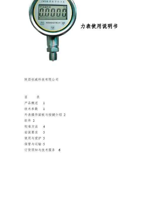
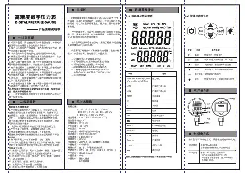
CWY系列精密数字压力表使用说明书CWY系列周密数字压力表使用讲明书陕西创威科技有限公司目录产品概述1技术参数1外表操作面板与按键介绍2软件2校准方法4安装要求5使用与爱护5保管与运输5订货须知与技术服务6一、产品概述CWY周密数字压力表是我公司按照国家最新标准研制生产的高精度智能压力测量外表。
CWY系列数字压力表要紧由压力传感器和信号处理电路组成。
采纳进口的压力传感器,性能优越,具有精度高、抗腐蚀性、抗冲击、抗震动、低温漂、高稳固性等优点;信号处理电路采纳最新的超低功耗处理器、信号处理芯片及电源治理芯片组成。
采纳大容量高性能锂电池供电,无需外部电源供电。
该外表外观精巧、小巧、美观,使用操作简单。
CWY系列周密数字压力表按压力特性可分为:表压、差压和绝压三种。
按压力量程可分为:微压、中低压、高压。
要紧应用于各级计量部门对各种压力(差压)变送器、一般压力表、血压计等其它压力仪器外表进行校验。
二、技术参数1.测量范畴:(-0.1~250)MPa2.输出信号:4~20mA、RS485、0~5V(可选)3.准确度等级:0.05级、0.1级、0.2级、0.4级4.显示方式:5位数字动态显示+模拟光柱指示5.过载压力:1.5~2倍的量程6.关闭电流:<20μA7.供电电源:3.6V高能双节锂电池,寿命2到3年8. 介质温度:(-45~120 )℃9.工作环境:温度:(-20~60)℃;湿度:≤85%RH;校正参比环境:(20±2)℃10.温度补偿范畴:(0~50)℃11.防爆级不:ExiaIICT412. 防护等级:IP6513. 过程接口:M20×1.5(外螺纹),专门的螺纹接口需要定制-1-三、外表操作面板与按键介绍采样状态下的功能:“开关”键:开关机功能键。
当外表不使用时能够关闭,以降低功耗。
用磁笔刷一下此键,2秒内显示该外表量程的起始点和满量程点,外表进入测量状态;再刷一下此键,2秒后外表进入关机状态。
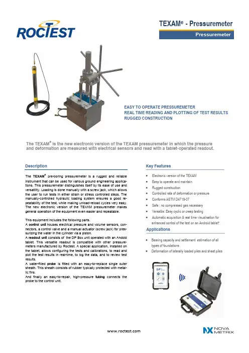
The TEXAM eis the new electronic version of the TEXAM pressuremeter in which the pressure and deformation are measured with electrical sensors and read with a tablet -operated readout.EASY TO OPERATE PRESSUREMETERREAL TIME READING AND PLOTTING OF TEST RESULTS RUGGED CONSTRUCTION∙ Electronic version of the TEXAM∙ Easy to operate and maintain ∙ Rugged construction∙ Controlled rate of deformation or pressure ∙ Conforms ASTM D4719-07 ∙ Safe : no compressed gas necessary ∙ Versatile: Easy cyclic or creep testing∙Automatic acquisition & real time visualisation for enhanced control of the test on an Android tablet*Key FeaturesDescriptionThe TEXAM epre -boring pressuremeter is a rugged and reliable instrument that can be used for various ground engineering applica-tions. This pressuremeter distinguishes itself by its ease of use and versatility. Loading is done manually with a screw jack, which allows the user to run tests in either strain or stress controlled steps. The manually -controlled hydraulic loading system ensures a good re-peatability of the test, while making unload -reload cycles very easy. The new electronic version of the TEXAM pressuremeter makes general operation of the equipment even easier and repeatable.This equipment includes the following parts.A control unit houses electrical pressure and volume sensors, con-nectors, a control valve and a manual actuator (screw jack) for pres-surizing the water in the cylinder via a piston.A readout unit consists of the DP Box unit operated with an Andoid tablet. This versatile readout is compatible with other pressure-meters manufactured by Roctest. A special application, installed on the tablet, allows configuring the tests and calibrations, to read and plot the test results in real -time, to log the data, and to review test results.A water -filled probe is fitted with an easy -to -replace single outer sheath. This sheath consists of rubber typically protected with metal-lic fins.And finally an easy -to -repair, high -pressure tubing connects the probe to the control unit.TEXAM e - Pressuremeter∙ Bearing capacity and settlement estimation of alltypes of foundations∙ Deformation of laterally loaded piles and sheet pilesApplicationsPlease specify:∙ Tubing length (25, 33 , or 50 m) ∙ Probe diameter∙ Accessories (metallic sheaths, rings) and optional itemsSpecificationsRoctest Ltd, 680 Birch Street St -Lambert, Quebec Canada J4P 2N3Phone +1 450 465 1113 Fax. +1 450 465 1938 ********************* Web Roctest reserves the right to make any changes in the specifications without prior noticeE5001E -180202Control unitWorking pressure 10 000 kPa (1500 psi) Dimensions40 x 46 x 125 cm (l x w x h) as-sembledWeight30 kg / 28 kg (Box / Actuator) D/P BOX Readout unitUser Interface Bluetooth communication with an Android tablet Resolution 1 kPa and 0.01 cm 3 Power Supply 2 x 12 V, 2.3 A, rechargeable batteriesDimensions 25 x 28 x 12 cm (l x w x h)Housing Splashproof, resistant ABS case Autonomy> 8 hours typicallyPower supply interfaceUniversal AC wall plug with US/Euro adapter + adapter cable for car (lighter) & for external batteryProbeDiameter 74 mm (N Long) / 44 mm (A) Length 72 cm / 84 cm Weight6.4 kg / 4.5 kg Max radial expansion35 %Test ProcedureThe probe is placed at the test depth in a pre -drilled borehole obtained by a method adapted to the soil conditions: wet rotary drilling, auger-ing, shelby tube pushing, etc. In granular soils below the water table, the probe can be driven directly within a slotted cas ing. The test is run either with a constant rate of deformation by using a uniform rate of rotation of the actuator, or with equal increments of p ressure as for the Menard pressuremeter test.Typical Pressuremeter Test ResultsTest ResultsAn in -situ stress -strain curve is obtained by plotting the injected vol-ume against pressure. The main parameters yielded from the test readings are the Pressuremeter Modulus, Creep Pressure, and the Limit Pressure. A tool (TexamCompanion) developed by Roctest can be used for that purpose.Ordering InformationOptional Accessories∙ A high -precision digital gage kit tobe connected on the front panel as a backup reading.∙ A mechanical volume counter to install on the handle shaft, also for backup reading.∙A slotted casing assembly compat-ible with A -size probe, for use in difficult soils (gravely soils).TEXAM e- PressuremeterDigital Pressure Gagae KitNote that the TEXAM eis compatible with the BOREMAC and PENCEL Probes - see sparate brochures for more details.Note: D/P BOX & Android Tablet sold separately。
CEP系列存储式电子压力计操作规程1、操作前,应首先详细阅读该装置的使用说明书,并应严格遵照说明书的要求操作。
2、工作软件双击“CEP存储式电子压力计”进入工作窗口,单击窗口上的“读压力计”、“写压力计”等按钮,会出现通讯窗口,软件自动检测可用通讯口,将通讯电缆连接在计算机的串行通讯口或USB通讯口,执行“开始”,通讯正常进行。
3、参数设置将压力计平放在桌上,卸下上接头,先将回放仪的通讯电缆的一头插入计算机空闲的串行口,另一头插入压力计的插座。
在“CEP存储式电子压力计”工作窗口中,单击“参数设置”,进入“工作参数设置”界面,“井名”必须人工输入,“设置时间”自动选取当前时间。
启动方式选择中“延时启动”和“压力启动”,根据测试需要单击选择。
“采样方式”中各参数设置完后,还有其它一些按钮,压力计在下井工作之前必须进行工作参数的设置,具体的工作参数根据测试目的而定。
4、数据处理“数据处理”完成从压力计活磁盘中读取测试数据;对数据中的异常点进行删除;根据需要绘制线性图或者对数图;对数据、图形进行打印等工作。
点击“数据处理”,然后点击“文件管理”中“打开”或“读压力计”将测试数据读入并显示在数据处理窗口,点击“隐藏数据”或“删除数据”(根据需要)隐藏或删除不需要的数据,点“存盘”保存数据,点“打印”,打印数据,点“图形显示”将数据用图形显示出来,点“打印图形”可打印图形。
另外,鼠标在图形内拖动,可显示对应点序号、时间、压力等信息。
5、标定(1)卸下绳帽、上接头、传压接头和导锥。
(2)给压力计设置好采样参数。
(3)传压线路排空后,把压力计装上去。
(4)恒温装置在所设定温度点至少恒温一个小时后,憋压让压力计启动测试,同时处于采集状态。
然后从零压开始,以一定的压力值为台阶依次升压,在每一压力台阶下稳定60秒,升至满量程后按相同的压力台阶依次降至零压,如此反复3次。
(5)让压力计处于通讯状态,计算机进入压力计软件的标定界面后,执行“读压力计”、“通讯”、输入标定温度等,最后把压力计标定曲线存盘。
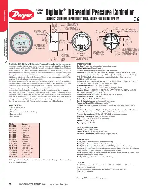
DWYER INSTRUMENTS, INC.| 20Digihelic ®Differential Pressure ControllerDigihelic ®Controller in Photohelic ®Gage, Square Root Output for FlowSeries DH3SPECIFICATIONSService:Air and non-combustible, compatible gases.Wetted Materials:Consult factory.Housing Material: Die cast aluminum case and bezel.Accuracy:±1.5% for 0.25˝ and ±0.25˝ w.c. ranges. Ranges 0.5˝ to 5˝ w.c. and corresponding bi-directional (except ±2.5˝ w.c.) ±1%; All other ranges: ±0.5% @77°F (25°C) including hysteresis and repeatability (after 1 hour warm-up).Stability:< ±1% per year.Pressure Limits:Ranges ≤ 2.5 in w.c.: 25 psi; ±2.5˝, 5 in w.c.: 5 psi; 10 in w.c.: 5psi; 25 in w.c.: 5 psi; 50 in w.c.: 5 psi; 100 in w.c.: 9 psi.Temperature Limits:32 to 140°F (0 to 60°C).Compensated Temperature Limits:32 to 140°F (0 to 60°C).Thermal Effects:0.020%/°F (0.036/°C) from 77°F (25°C). For 0.25˝ and ±0.25˝w.c. ranges: ±0.03%/°F (±0.054%/°C).Power Requirements:12-28 VDC, 12-28 VAC 50 to 400 Hz.Power Consumption:3 VA max.Output Signal: 4-20 mA DC into 900 ohms max.Zero & Span Adjustments:Accessible via menus.Response Time:250 ms (damping set to 1).Display:Backlit 4 digit LCD 0.4˝ height LED indicators for set point and alarm status.Electrical Connections:15 pin male high density D-sub connection. 18˝ (46 cm)cable with 10 conductors included. 4´ and 10´ cables available.Process Connections:1/8˝ female NPT. Side or back connections.Mounting Orientation:Mount unit in vertical plane.Size:5˝ (127 mm) OD x 3-1/8˝ (79.38 mm).Weight:1.75 lb (794 g).Agency Approvals:CE.SWITCH SPECIFICATIONS Switch Type:2 SPDT relays.Electrical Rating:1 amp @ 30 VAC/VDC.Set Point Adjustment:Adjustable via keypad on face.The Series DH3 Digihelic ®Differential Pressure Controller is a 3 in 1 instrument possessing a digital display gage, control relay switches, and a transmitter with current output all packed in the popular Photohelic ®gage style housing. Combining these 3 features allows the reduction of several instruments with one product, saving inventory, installation time and money. The Digihelic ®controller is the ideal instrument for pressure, velocity and flow applications, achieving a 1% full scale accuracy on ranges down to the extremely low 0.25 in w.c. to 2.5 in w.c. full scale. Ranges of 5 in w.c. and greater maintain 0.5% F.S.accuracy. Bi-directional ranges are also available.The Series DH3 Digihelic ®controller allows the selection of pressure, velocity or volumetric flow operation in several commonly used engineering units. 2 SPDT control relays with adjustable deadbands are provided along with a scalable 4-20 mA process output.Programming is easy using the menu key to access 5 simplified menus which provide access to: security level; selection of pressure, velocity or flow operation; selection of engineering units; K-factor for use with flow sensors; rectangular or circular duct for inputting area in flow applications; set point control or set point and alarm operation; alarm operation as a high, low, or high/low alarm; automatic or manual alarm reset; alarm delay; view peak and valley process reading; digital damping for smoothing erratic process applications; scaling the 4-20 mA process output to fit your applications range and field calibration.APPLICATIONS•SCFM flow in ducts •Filter status•Static pressures in ducts or buildings •Damper control •Fan controlSee page 567 for process tubing options.*Velocity and volumetric flow not available on bi-directional range units and models DH3-010 and DH3-011.OPTIONSFor NIST traceable calibration certificate, add suffix -NIST to model numbers.Example DH3-004-NIST.For factory calibration certificate, add suffix -FC to model numbers.Example DH3-004-FC.ACCESSORIESA-298, Flat Aluminum Bracket for flush mountingA-301,Static Pressure Tip for 1/4˝ metal tubing connectionA-302,Static Pressure Tip for 3/16˝ and 1/8˝ I.D. plastic or rubber tubingA-302F-A,303 SS Static Pressure Tip with mounting flange. For 3/16˝ ID rubber or plastic tubing. 4˝ insertion depth. Includes mounting screwsA-370, Mounting Bracket flush mount bracket. Bracket is then surface mounted. Steel with gray hammertone epoxy finishA-489,4˝ Straight Static Pressure Tip with Flange。
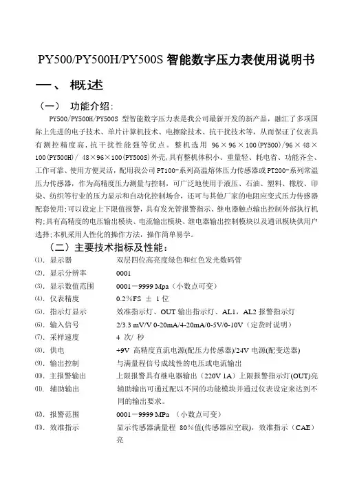
PY500/PY500H/PY500S智能数字压力表使用说明书一、概述(一)功能介绍:PY500/PY500H/PY500S型智能数字压力表是我公司最新开发的新产品,融汇了多项国际上先进的电子技术、单片计算机技术、电擦除技术、抗干扰技术等,从而保证了仪表具有测控精度高,抗干扰性能强等优点。
整机选用96×96×100(PY500)/96×48×100(PY500H)/ 48×96×100(PY500S)外壳,具有整机体积小、重量轻、耗电省、功能齐全、工作可靠、使用方便灵活,配用我公司PT100-系列高温熔体压力传感器或PT200-系列常温压力传感器,作为高精度压力测量与控制,可广泛地使用于液压、石油、塑料、橡胶、印染、纺织等行业的压力显示和自动化控制场合,还可与其他厂家的电阻应变式压力传感器配套使用;可以设定上下限值报警,具有发光管报警指示、继电器触点输出控制外部执行机构;具有高精度的电压输出模块、电流输出模块、继电器输出控制模块以及通讯模块供用户选择;本机采用人性化的操作方法,操作简单易学。
(二)主要技术指标及性能:⑴.显示器双层四位高亮度绿色和红色发光数码管⑵.显示分辨率0001⑶.显示数值范围0001-9999 Mpa(小数点可变)⑷.仪表精度0.2%FS ±1位⑸.指示灯显示效准指示灯、OUT输出指示灯、AL1,AL2报警指示灯⑹.输入信号2/3.3 mV/V 0-20mA/4-20mA/0-5V/0-10V(定货时说明)⑺.采样速度 4 次/ 秒⑻.供电+9V 高精度直流电源(配压力传感器)/24V电源(配变送器)⑼.输出控制与满量程信号成线性的电压或电流输出⑽.主报警输出上限报警具有继电器输出(220V 1A)上限报警指示灯(OUT)亮⑾.辅助输出辅助输出可通过配以不同的功能模块并通过仪表设定来达到不同的输出要求。
⑿.报警范围0001-9999 MPa (小数点可变)⒀.效准指示显示传感器满量程80%值(传感器应空载),效准指示(CAE)亮⒁.使用温度及湿度 0-55 ℃ ,≤ 80% RH ⒂.电源要求 85-265 V AC 50Hz - 60Hz⒃.外型尺寸 96×96×100mm/96×48×100 mm 48×96×100mm ⒄.开孔尺寸 92×92mm /92×46mm /46×92mm ⒅.自身重量约 400克/200克//200克(三)模块功能说明PY500/PY500H/PY500S 智能数字压力表有2个功能模块插座,通过安装不同的模块可以实现不同的功能及类型输出。
电子压力计使用说明书一、产品简介电子压力计是一种用于测量气体或液体压力的仪器,采用先进的电子技术和传感器,具有高精度、高稳定性和可靠性等特点。
本说明书将详细介绍电子压力计的使用方法及注意事项,帮助用户正确使用该产品。
二、产品结构电子压力计由以下几个部分组成:1. 具有数字显示屏的主控面板:用于显示测量结果和设定参数。
2. 压力传感器:接收被测介质的压力并将其转换成电信号。
3. 连接线:连接主控面板和传感器。
4. 电源供应器:为电子压力计提供电力支持。
三、使用方法1. 将主控面板和传感器连接好,并确保连接稳固可靠。
2. 打开电源供应器,使其为电子压力计提供电力。
3. 打开主控面板,确认显示屏处于正常状态。
4. 设定参数:根据需要测量的压力范围和单位,在主控面板上选择相应的设置。
5. 进行测量:将传感器连接到被测介质上,保证接触良好,并等待一段时间使测量结果稳定。
6. 读取测量结果:测量结果将在主控面板的数字显示屏上显示出来。
7. 关闭电子压力计:使用完毕后,先关闭主控面板,再关闭电源供应器。
四、注意事项1. 保持清洁:定期清洁传感器和主控面板,避免灰尘或杂物进入。
2. 避免强烈震动:使用过程中应避免剧烈震动,以免影响测量精度。
3. 防止过载:确保被测压力不超过电子压力计的额定范围,以免损坏传感器。
4. 避免潮湿环境:电子压力计不能长时间接触水或潮湿环境,以免影响正常使用。
5. 防止过热:避免将电子压力计放置在高温环境中,以免影响性能和安全性。
6. 使用适当压力密封件:在连接传感器和被测介质时,选择适当的压力密封件,确保连接紧密可靠。
五、维护保养1. 定期校准:电子压力计应定期进行校准,以确保测量结果的准确性。
2. 保持干燥:在不使用电子压力计时,应将其存放在干燥通风的地方,防止潮湿和腐蚀。
3. 避免尖锐撞击:在携带或移动电子压力计时,应避免与尖锐物体碰撞,以免损坏传感器或主控面板。
六、故障排除1. 如果主控面板无显示或显示不正常,检查电源供应器是否正常工作,检查连接是否稳固。
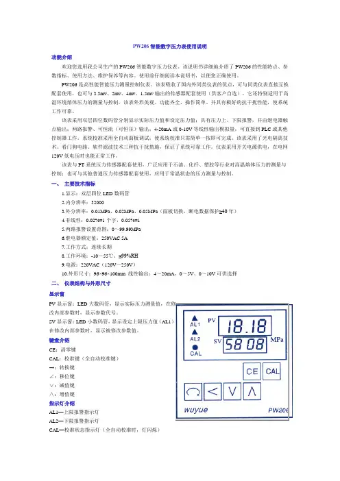
PW206智能数字压力表使用说明功能介绍欢迎您选用我公司生产的PW206智能数字压力仪表。
该说明书详细地介绍了PW206的性能特点、参数指标、使用方法、维护保养等内容。
使用前仔细阅读本说明书,以便您正确使用。
PW206是高性能智能压力测量控制仪表。
该表吸收了国内外同类仪表的优点,可与同类仪表直接互换配套使用,也可与3.3mv、2mv、4mv、1.5mv输出的传感器配套使用(供客户自选),它还特别适用于高温环境熔体压力的测量与控制。
该表外形美观、功能齐全、操作简单、并具有极好的抗干扰性能,使系统工作可靠。
该表采用双层四位数码管分别显示实际压力值和设定压力值;具有压力上、下限报警,并由继电器触点输出;两路报警、可恒流(可恒压)输出;4-20mA或0-10V等线性输出模拟量,可直接到PLC或其他控制器工作。
系统校准采用全自动面板调试;使系统校准只需简单一按即可完成。
该表采用了光电隔离技术、看门狗电路、软件滤波技术三种抗干扰措施,保证了系统可靠工作。
仪表采用开关电源供电,在电网120V低电压时也能正常工作。
该表与PT系统压力传感器配套使用,广泛应用于石油、化纤、塑胶等行业对高温熔体压力的测量与控制;也可与其他普通压力传感器配套使用,应用于常温状态的压力测量与控制。
一、主要技术指标1.显示:双层四位LED数码管2.内分辨率:320003.外分辨率:0.01MPa、0.02MPa、0.05MPa(面板切换,断电数据保护≥40年)4.非线性:0.02%±1个字,0.05%±15.两路报警设置范围:0~99.99MPa6.继电器额定值:250VAC 5A7.工作方式;连续长期8.工作环境:-10~55℃、≤99%RH9.电源:220VAC(120V~250V)10.外形尺寸:96×96×100mm 线性输出:4~20mA,0~5V、0~10V可供选择二、仪表结构与外形尺寸显示窗PV显示窗:LED 大数码管,显示实际压力测量值,在修改内部参数时,显示参数代号。
Operating InstructionsDPG 109Vacuum Measuring AndControl UnitPG0005KJL/E(0508)21.Safety Instructions . . . . . . . . . . . . . . . . . . . . . . . . . . . . . . . . . . . . . . . . . . . . . . .31.1.For Your Orientation. . . . . . . . . . . . . . . . . . . . . . . . . . . . . . . . . . . . . . . . . . . . . . . . . . . . . . . . . 42.Understanding The DPG 109 . . . . . . . . . . . . . . . . . . . . . . . . . . . . . . . . . . . . . . .52.1.Main Features . . . . . . . . . . . . . . . . . . . . . . . . . . . . . . . . . . . . . . . . . . . . . . . . . . . . . . . . . . . . . 5Proper Use. . . . . . . . . . . . . . . . . . . . . . . . . . . . . . . . . . . . . . . . . . . . . . . . . . . . . . . . . . . . . . . . 6Improper Use. . . . . . . . . . . . . . . . . . . . . . . . . . . . . . . . . . . . . . . . . . . . . . . . . . . . . . . . . . . . . . 62.2.Package Contents . . . . . . . . . . . . . . . . . . . . . . . . . . . . . . . . . . . . . . . . . . . . . . . . . . . . . . . . . . 63.Installation . . . . . . . . . . . . . . . . . . . . . . . . . . . . . . . . . . . . . . . . . . . . . . . . . . . . . .73.1.Preparation For Installation . . . . . . . . . . . . . . . . . . . . . . . . . . . . . . . . . . . . . . . . . . . . . . . . . 73.2.Mains Connection. . . . . . . . . . . . . . . . . . . . . . . . . . . . . . . . . . . . . . . . . . . . . . . . . . . . . . . . . . 73.3.Transmitter Connection. . . . . . . . . . . . . . . . . . . . . . . . . . . . . . . . . . . . . . . . . . . . . . . . . . . . . 83.4. PC Connection (RS 232). . . . . . . . . . . . . . . . . . . . . . . . . . . . . . . . . . . . . . . . . . . . . . . . . . . . . 93.5.Relay Output . . . . . . . . . . . . . . . . . . . . . . . . . . . . . . . . . . . . . . . . . . . . . . . . . . . . . . . . . . . . . 104.Operation . . . . . . . . . . . . . . . . . . . . . . . . . . . . . . . . . . . . . . . . . . . . . . . . . . . . . .114.1.First-Time Operation. . . . . . . . . . . . . . . . . . . . . . . . . . . . . . . . . . . . . . . . . . . . . . . . . . . . . . . 114.2.Switching On The Unit . . . . . . . . . . . . . . . . . . . . . . . . . . . . . . . . . . . . . . . . . . . . . . . . . . . . . 124.3.Measuring Mode . . . . . . . . . . . . . . . . . . . . . . . . . . . . . . . . . . . . . . . . . . . . . . . . . . . . . . . . . 124.4.Configuration Mode (Overview Of Menu Options). . . . . . . . . . . . . . . . . . . . . . . . . . . . . 124.5.General Procedure For Parametering. . . . . . . . . . . . . . . . . . . . . . . . . . . . . . . . . . . . . . . . 144.5.1.Menu «PRESSURE». . . . . . . . . . . . . . . . . . . . . . . . . . . . . . . . . . . . . . . . . . . . . . . . . . . . . . . . 154.5.2.Menu «CHANNEL MENU». . . . . . . . . . . . . . . . . . . . . . . . . . . . . . . . . . . . . . . . . . . . . . . . . . 16Gas Type Correction Factor («CHANNEL MENU»). . . . . . . . . . . . . . . . . . . . . . . . . . . . . . 17Retro Adjustment («CHANNEL MENU»). . . . . . . . . . . . . . . . . . . . . . . . . . . . . . . . . . . . . . 18Degassing («CHANNEL MENU»). . . . . . . . . . . . . . . . . . . . . . . . . . . . . . . . . . . . . . . . . . . . 194.5.3.Menu «RELAY MENU». . . . . . . . . . . . . . . . . . . . . . . . . . . . . . . . . . . . . . . . . . . . . . . . . . . . . 204.5.4.Menu «COMMON MENU». . . . . . . . . . . . . . . . . . . . . . . . . . . . . . . . . . . . . . . . . . . . . . . . . . 224.6 Communication Via RS 232 Interface . . . . . . . . . . . . . . . . . . . . . . . . . . . . . . . . . . . . . . . . 235.Error Signals . . . . . . . . . . . . . . . . . . . . . . . . . . . . . . . . . . . . . . . . . . . . . . . . . . .256.Maintenance, Service . . . . . . . . . . . . . . . . . . . . . . . . . . . . . . . . . . . . . . . . . . . .267.Technical Data . . . . . . . . . . . . . . . . . . . . . . . . . . . . . . . . . . . . . . . . . . . . . . . . .277.1.Data Listings. . . . . . . . . . . . . . . . . . . . . . . . . . . . . . . . . . . . . . . . . . . . . . . . . . . . . . . . . . . . . . 277.2.Dimensions Diagram . . . . . . . . . . . . . . . . . . . . . . . . . . . . . . . . . . . . . . . . . . . . . . . . . . . . . . 278.Accessories . . . . . . . . . . . . . . . . . . . . . . . . . . . . . . . . . . . . . . . . . . . . . . . . . . . .289.Supplementary Information . . . . . . . . . . . . . . . . . . . . . . . . . . . . . . . . . . . . . . .28IndexPagePlease note!Current operating instructions are available at 1. Safety Instructions☞Read and follow all the instructions in this manual.☞Inform yourself regarding:–Dangers which can be caused by the unit–Dangers which can be caused by the system☞Observe the safety and accident prevention instructions.☞Check regularly that the safety procedures are being complied with.☞Take into account the prevailing environmental conditions when installing the DPG 109.☞The protection type is IP 20.☞Take account of the relevant instructions when handling the process media and observe the safety procedures.☞Take account of the possible reactions between materials and process media.☞Take account of possible reactions in the process media resulting from the spontaneous warming of the product.☞Do not carry out any unauthorized modifications to or conversions on the unit.☞When returning the unit to the manufacturer please follow the shipping instructions.☞Before beginning work, inform yourself regarding the existence of any possible contamination.☞When handling contaminated parts observe the relevant instructions and follow the safety procedures.☞Ensure that all other users receive the safety instructions.ValidityThese operating instructions describe the installation and operation of the Digital Vacuum Measurement And Control Unit DPG 109 with the part number KTG15010. The part number appears on the rating plate.To ensure the avoidance of possible product identification errors in any correspondence with the Kurt J. Lesker Company please always state the part number appearing on the rating plate.This document is based on the component software version 1.30.Technical modifications reserved.3DPG 1097If the unit is to be fitted into a rack, mains voltage must be supplied via a terminal box.3. Installation0031Kurt J.Lesker Company 1925 Worthington Ave Clairton, PA 15025 。
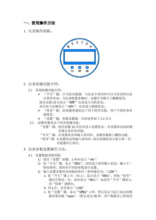
一、使用操作方法1.仪表操作面板:2.仪表按键功能介绍:2.1 常规按键功能介绍:“开关”键:开关机功能键,当仪表不使用时可以关闭采样以延长使用寿命;当仪表配置参数时,该键作为数字上翻键使用;按住此键1S 内显示“OFF”仪表进入关机状态;再次按下此键显示“-ON-”,仪表进入测量状态;“校零”键,此按键普通状态下用于校零功能,用户不要轻易单独使用。
“设置”键:参数设置键,具体说明如下2.2及32.2 .设置参数状态下的各按键功能:“设置”键:按住此键1S内仪表进入设置状态。
在设置状态按此键有确认保存的功能;“开关”键:在设置状态和输入密码时,该键有数据上翻的功能;“校零”键:在设置状态和输入密码时,按住此键将显示值左移一位,并能循环左移位。
3.仪表参数设置操作方法:3.1设置数据采集间隔1)按住“设置”按键,1秒内显示“-bb-”2)按“开关”键,显示“0001”,此时进入密码输入状态,输入不一样的密码,则将对不同的参数进行设置;3)输入设置采集时间间隔的密码(密码通常为:“1200”)a. 按“开关”键1次(加1),显示显示“0001”,再按“校零”键向左移动一位,此时显示“0011”;如此用“开关”键加1,用“校准”键移位。
b. 同a步,直至显示“1200”c. 按“设置”键,显示“SPEd”1秒,然后显示当前已设定的数据采集间隔“xxxx”,(默认设为30秒,用户根据自己的使用使用寿命情况设定),然后仪表进入采集时间设置,d. 按“开关”键1次(加1),显示“0001”,再按“校零”键向左移动一位,此时显示“0011”;如此用“开关”键加1,用“校准”键移位。
e. 同d步,输入采集间隔(单位为秒);f. 按“设置”键,对输入的参数进行保存,并显示“bbbb”,表明参数设置成功,2秒后设备进入正常的数据采集状态;3.2 设置设备对应的目标接收RTU地址,此参数决定了本设备所对应的RTU。
1)按住“设置”按键,一秒内显示“-bb-”2)按“开关”键,显示“0001”,此时进入密码输入状态,输入不一样的密码,则将对不同的参数进行设置;3)输入设置目标RTU地址的密码(密码通常为:“1300”)a. 按“开关”键1次(加1),显示“0001”,再按“校零”键向左移动一位,此时显示“0011”,如此用“开关”键加1,用“校准”键移位。
京制00000186号使用产品前,请阅读使用说明书专利产品专利号:86208794BJ-2 型精密数字气压计使用说明书中国航天空气动力技术研究院2012年1月20日发布一、 概述:BJ-2型精密数字压力计是以我院独创的大气压力传感器(专利号86208794)为核心部件,结合当代单片机技术,成功开发适用于学校和科研单位实验室的一款智能型测压仪器。
其主要用途是替代水银气压计,水柱式压力计,并具有气压高度计的功能。
由于它具有技术指标先进,结构牢靠,使用方便,价格实惠等特点,定将成为广大用户喜欢的产品。
我们将竭诚为您服务。
二、 结构和工作原理:本仪器由气压探头组件、面板组件、电源组件和机壳、机箱组成。
其工作原理方框图如下:其中气压感受装置是由真空波纹管和环形弹性元件构成的弹性系统,机电转换装置采用应变电桥,信号放大部分采用低漂移集成运算放大器,这三部分构成气压探头组件,其电路部分全部用硅橡胶灌封。
数字显示采用214位液晶数字面板表,它和模/数转换,信号处理部分一起构成面板组件。
电源部分是一个全密封的蓄电池组,它由10只氢镍可充电池及限流电阻构成,全部用704硅橡胶灌封,是一个可靠电源组件。
三、 技术指标:1、量程范围:600.0-1250.0hPa (绝对档)±19999Pa (相对档)±999.9m (测高档)2、分辨:0.1hPa (绝对), 1Pa (相对),0.1m (测高)3、精度:±1hPa (绝对,校准周期三个月至一年),±10Pa (±10000pa,相对),±20Pa (±19999pa,相对),±0.5m (测高)。
4、温度系数:小于2Pa/℃5、耐振性:正常碰撞、振动带来的显示变化小于2Pa 。
6、显示及功能:214位液晶数字面板表,可显示绝对气压值(hPa),相对气压值(Pa),相对高度值(m ),电源电压(V)。
ISE80系列压力开关设定说明设定顺序:通电—测量模式—零点校正—功能设定—测量模式产品通电后,自动进入压力测量模式,第一次使用时,请按如下顺序操作。
1、零点校正:产品第一次使用时,通电且不施加气压时,如果显示值不为零,和键同时按住1s 以上,显示值归零。
2、功能设定:测量模式下按住键2s 以上,压力开关进入功能设定模式,显示屏显示为。
按和键选择对应功能后按进入详细功能设置。
备注:部分功能为可选功能,根据型号而定。
特定型号下如果不包含某可选功能,对应位置显示。
全部功能列表:项目出厂设置 F0:单位选择功能 ISE :Mpa,ZSE :Kpa P (可选):psi F1:OUT1规格设定 迟滞模式,常开 F2:OUT2规格设定 迟滞模式,常开 F3:响应时间设定 2.5 ms F4:模拟输出/自动移位输入 模拟F5:显示精度设定 1/1000 F7:显示值校正 0% F8:自动预设功能设定 手动 F9:节能模式设定 OFF F10: 密码功能设定OFF1) F0-单位选择功能可选功能,部分型号无此功能。
单位不同,显示屏开显示的数值范围不同。
操作方法:按和键选择对应单位,按键确认。
按住键2s 以上功 能 选 择 模 式功能设定测量模式按键进入单位选择模式按和键选择对应单位交替显示按键完成设定返回到功能选择模式,屏幕显示F0F0-单位选择功能设定完成2)F1-OUT1规格设定方法此部分可设置输出类别(迟滞型/比较型)和输出模式(常开/常闭)设定。
输出模式出厂时默认设置常开型迟滞模式(出厂时默认设置)输出迟滞(H-1)压力比较模式(也称窗口比较模式)输出迟滞(H1)迟滞(H1)压力迟滞模式(出厂时默认设置)输出迟滞(H-1)压力比较模式(也称窗口比较模式)输出迟滞(H1)迟滞(H1)压力常闭型功能选择模式下按和至屏幕显示,然后按进入OUT1规格设定。
压力设定状态:此状态下设定压力开关输出的ON/OFF 点。
电话************** 传真**************/ e-mail :**************第 1 页一、概述感谢您选用我公司生产的NY202系列智能压力仪表!此说明书详细介绍了NY202 表的性能特点、参数指标、使用方法、维护保养等内容。
使用前请仔细阅读本说明书,以便您正确使用。
NY202 表是高性能智能数字压力测试控制仪。
该表吸收了国内外同类仪表的优点,可与同类仪表直接互换使用。
它还特别适用于高温环境熔体压力的测量与控制。
该表外形美观、功能齐全、操作简单、维护方便、工作可靠。
该表采用双排四位LED 数码管(4×2)分别显示实际压力值和设定压力值;具有两路继电器触点报警输出、两路恒流(或恒压)模拟变送输出(一路为比例式输出可供记录仪,另一路为PID 式调节输出可供变频器);系统校准通过面板按键自动完成;该表采用了光电隔离技术、看门狗电路、软件滤波技术等多种抗干扰措施,保证了系统可靠工作。
该表与高温熔体压力传感器配套使用,广泛应用于石油、化纤、塑胶等行业对高温熔体压力的测量与控制;与普通压力传感器配套使用,应用于常温状态下的压力测量与控制;也可以与其他类型传感器配套使用,用于(张)力、重量、位移、扭矩、液位等物理量的测量与控制。
二、 主要技术指标⒈ 显 示:双排四位LED 数码管 ⒉ 内分辨率:32000⒊ 显示分度:1、2、5(内部参数Pdv 决定) ⒋ 非 线 性: 0.2% 、0.1%、0.05% ⒌ 报警范围:0∼配套传感器量程⒍ 输出控制:两路继电器:250V AC ×5A ⒎ 模拟输出:两路信号0/4-20mA、或0/1-5/10V ⒏ 工作方式:连续长期⒐ 工作环境:-10∼55℃、 ≤90%RH ⒑ 电源:85∼265V AC 、48∼62Hz 、8W ⒒ 开口尺寸:92×92×100mm 92×44×100mm 或+12V DC ×300mA、或+24V DC ×300mA三、 仪表结构与外形尺寸四、 显示与键盘电话**************传真**************/ e-mail :**************第 2 页4.1 前面板图4.2显示PV 显示窗: 四位0.50’/0.40’LED 数码管,显示实际(即过程)压力测量值; 在修改内部参数时,显示参数代号。
电子压力计使用说明书一、电子压力计说明书电子压力计是一款低功耗、高精度、高分辨率的蓝宝石井下存储电子压力计,具有良好的密封性,抗腐蚀性。
可以在高温、高压等恶劣环境下,正常工作。
电子压力计1、电子压力计各部件说明及标准配置。
<1> 电池筒:<2> 导锥<3>、压力计<4>、绳帽:<5>、电池<6>、连接线<7>、接口箱每箱电子压力计标准配置:两只电子压力计两个电池筒两个个导锥一个绳帽一个维修包(包括6个特别的O圈)一个USB接口箱(两只电子压力计配一个)标定证书操作软件两节节锂电池2、电子压力计工作模式电子压力计被设计成在低耗电量下工作,因此可以延长电池的寿命,以节省用户的开支。
<1> 采样模式:当电池接上压力计时压力计便进入了采样模式,而不是接口箱或连接线缆接上压力计时。
在正常操作的情况下,压力计会在现场被编程,然后运到井口,下井之前压力计应该是工作正常,且电池与压力计是连接在一起的,压力计执行相关的程序,这些程序是事先编辑好并保存在压力计里的。
<2> 休眠模式:当压力计没有采样时就会处于休眠状态(例如,两个采样点之间的时间)。
所有的压力计都被设计为:当一次采样完成之后,就会自动的转换到休眠模式。
<3> 通信模式:当接口箱和连接线把压力计连接到计算机上时,压力计就处于了通信模式。
通信模式用于压力计编程,下载数据文件,上传标定信息以及通过操作软件做一些与操作相关的其它事情。
3、装配和操作一旦编程被保存到压力计里,在操作能够发生之前,在压力计的装配上会有一个简单的步骤。
<1> 把电池连接到压力计之前,用我们的电池测试器检测它的电压。
任何一组新的标准的150℃AA锂电池的电量是3.6V-3.9V。
当电池的起始电压低于厂家所要求的值时,不要再使用该电池。
如果一组新电池的电压低于它所预期的值时,这也许是电池的钝化层所引起的。
费斯托数显压力表说明书费斯托数显压力表是一种用于测量流体压力的仪器,广泛应用于工业自动化控制系统、实验室和现场操作等领域。
下面是费斯托数显压力表的说明书内容:一、产品介绍:费斯托数显压力表是一种采用微电子技术和半导体传感器原理制作而成的压力测量仪器。
它能够准确测量液体或气体的压力,并将测得的数值以数字形式显示在液晶屏上。
该数显压力表具有测量范围广、分辨率高、响应速度快等特点,适用于各种流体压力的监测和控制。
二、产品特点:1. 高精度:内置高精度的压力传感器,具有较低的测量误差。
2. 数字显示:采用液晶屏显示压力数值,直观清晰。
3. 范围广:可根据用户需求选择不同的测量范围。
4. 高稳定性:采用先进的温度补偿技术,能够提高仪器的稳定性。
5. 耐压性强:具有良好的耐压性能,适用于高压环境下的测量。
三、使用方法:1. 将数显压力表与被测介质连接,确保连接口密封。
2. 打开数显压力表的电源开关,此时仪表将自动进行自检。
3. 等待液晶屏显示正常后,即可读取压力数值,单位为帕斯卡(Pa)或其它用户自定义的单位。
4. 如果需要对数显压力表进行校准或配置参数,可以按照说明书进行相应设置。
四、注意事项:1. 在使用数显压力表前,请先阅读整本说明书,确保正确操作。
2. 在清洁仪器时,避免将水或液体溅入仪表内部,以免损坏电子元件。
3. 不要在高温、高湿度或腐蚀性气体的环境中使用数显压力表。
4. 不要过度震动、碰撞或重压数显压力表,以免损坏仪器。
5. 定期对数显压力表进行维护保养,确保其长期稳定工作。
以上是费斯托数显压力表的简要说明书,具体操作细节和安全注意事项请参考产品附带的详细说明书。
O P E R A T I N G M A N U A LE n g l i s hTHE SYSTEM®Digital Pressure GaugeE n g l i s hAttention!This Digital Pressure Gauge is according to EN 250 a piece of safety equipment of a SCUBA. It may only be completed to a complete SCUBA with components, which passed the EU-Certification and come up to the EN 250 norm.According to the EN 250 a complete SCUBA consists at least of the following components:a)Air pressure tank(s) and tank valve(s)b)Regulatorc)Safety equipmentd)Frame or holding device for air cylinder(s) with the possibility to mount the harnesse)Carrier devicef)Breathing connection (face mask and mouthpiece, full face mask, or diving helmet)g)Instructions for use must be includedThe high-pressure hose of the Digital Pressure Gauge is equipped at its connection (7/16“) with a flow through reduction.According the law of technical working devises we point to the following points:•Base of each use of the Digital Pressure Gauge and its component parts is the knowledge and conside-ration of this Manual.•The Digital Pressure Gauge may only be used for the purposes mentioned in this manual or confirmed in writing by Uwatec.•The Digital Pressure Gauge has to be yearly inspected (inspection-maintenance-reparation) by an educa-ted authorised person. These inspections have to be recorded. Only original Uwatec spare parts may be used for replacements.•The EN 250 Certification maximum depth is 50 m.Important remarks concerning words and symbolsThis operating manual makes use of the following icons to indicate especially important comments:Remarks:Information and tips which are important for optimal use of your the Digital Pressure Gauge.Attention!Indicates information about specialities which are important to prevent a risky situation and to dive more comfortably.E List of chaptersIntroduction / Overview . . . . . . . . . . . . . . . . . .6Safety considerations / Warnings . . . . . . . . . . . .7 Set Up ProcedureSwitching the unit on and off . . . . . . . . . . . . . .9Before the first dive . . . . . . . . . . . . . . . . . . . .10User Mode / . . . . . . . . . . . . . . . . . . . .10 . . . . . . . . .11•Set Up pressure and temperature unit . . . .13Mounting the high-pressure hose to thefirst stage . . . . . . . . . . . . . . . . . . . . . . . . . . .14Connecting the Digital Pressure Gauge . . . . . .14Disconnecting the Digital Pressure Gauge . . . .16Measurement Mode . . . . . . . . . . . . . . . . .18Preparation for the Dive . . . . . . . . . . . . . . . . .19Logbook . . . . . . . . . . . . . . . . . . . . . . . . .19Battery Warning . . . . . . . . . . . . . . . . . .20 . . . . . . . . . . . . . . . .21Trouble Shooting . . . . . . . . . . . . . . . . . . . . . .22Technical Information . . . . . . . . . . . . . . . . . . .23Warranty . . . . . . . . . . . . . . . . . . . . . . . . . . . .24EC type-approval . . . . . . . . . . . . . . . . . . . . . .25Overview user interface . . . . . . . . . . . . . . .26, 27Serial No. / Dealer address . . . . . . . . . . . . . . .28Introduction / OverviewThe Uwatec Digital Pressure Gauge measures the tank pressure and displayshose connects the Digital Pressure Gauge on the first stage of the diving tank.The Digital Pressure Gauge has two pressure alarm values. One is fixed at 50bar, the other one can be set by the user between 30 and 100 bar (450-1500psi). The Digital Pressure Gauge warns the diver optically and acoustically ifthe tank pressure falls short off one of these pressure alarm values.Furthermore the diver can select the units for the pressure and temperatureindication.The logbook stores the original and the final tank pressure of a given dive anddisplays the pressure difference.E n g l i s hSafety considerations / WarningsSafety considerations / WarningsSet Up ProcedureSet Up ProcedureBefore the first diveBefore the first dive the value of the tank pressure alarm and the units for thepressure and temperature indication has to be set. Without new settings thedefault settings will be valid.User Mode/The User Mode allows to…•read the logbook (pressure difference, pressure at the beginning and at theend of a dive). See page 19.•set the value of the user selectable tank pressure alarm. Setting can bemade between 30 and 100 bar (450-1500 psi) in steps of 10 bar (150 psi).See page 11.•select the unit of the pressure and temperature indication. See page 13.On page 26 and 27 a graphical overview of the user interface is shown.be reduced below 8 bar (120 psi) to enter into the User Mode.The User Mode will be left automatically after 3 minutes (switching off) or ifthe tank pressure exceeds 8 bar (120 psi).The User Mode is programmed as a loop, which can be run through by bridgingB and S, as many times you want. See also overview user interface, page 26.If the User Mode is left during the setting of the tank pressure alarm or theunits, the indicated value will not been taken in to account, the old settingwill be kept.Set up the tank pressure alarmown tank pressure alarm value. See also page 6 and 18.and the tank pres-are indicated.untilOverview set uptank pressurealarmEach bridging of the contacts B and S increases the value of the tank pressure alarm by 10 bar (150psi). When the pressure alarm setting reaches 100bar (1500 psi) the next contact of B, S will loop thealarm setting to 30 bar (450 psi).Bridging the contacts B and E confirms the actualdisplayed value as the new tank pressure alarm andthe displayed alarm value stops flashing. If the mea-sured pressure falls short of this value, the DigitalPressure Gauge activates the tank pressure alarm.and both theBridging B and E confirms the displayed units as the new combination. The displayed units stop flashing.E n g l i s h until OverviewunitsMounting the high-pressure hose to the first stage2.Tighten the connection with a matching wrench.If the pressure exceeds 8 bar the Digital Pressure Gauge switches automati-cally to the Measurement Mode (see page 17).E n gl i s hE n g l i s h In the Measurement Mode the Digital Pressure Gauge indicates the tank pres-sure (numerically and graphically) and the temperature. The Digital Pressure Gauge activates an optical and acoustical alarm if the tank pressure goes below the fixed 50 bar alarm or below the user selected alarm pressure value.measured maximum pressure. If the maximum pressure exceeds 250 bar (3600 psi) the number of bars is displayed as a proportion of 300 bar (4500psi). With a maximum pressure of less than 250 bar (3600 psi) the number of bars is proportional to 200 bar (3000 psi).Measurement ModeModeTank Pressure Alarm,In the Measurement Mode the unit alarms the diver if the pressure falls shortof the set value of the tank pressure alarm or 50 bar (750 psi). The alarms,given acoustically and graphically, warn about the danger of not havingenough air until the end of the dive.The alarms are given on the surface and under water.symbol gets indicated and an acoustic alarm signal is given.If the pressure falls under the selected value of the tank pressure alarm, theunit repeats after every 5 bar (50 psi) pressure reduction the acoustical alarmsignal.Preparation for the DiveMake sure before each dive that the• Digital Pressure Gauge is correctly mounted (see page 14)• selected value of the tank pressure alarm is high enough (see page 11)LogbookThe logbook stores the tank pressure at the beginning and the end of the last dive and displays the pressure difference.appears.E n g l i s hPressure difference:Beginning/endLogbookIf the tank pressure exceeds 8 bar, the unit switches to the MeasurementMode. After 3 minutes in the Logbook Mode, it switches off automatically.The User Mode is programmed as a loop that can be run through by bridgingB and S, as many times you want. See overview user interface page 26.The Logbook stores the pressure data of a dive if the pressure has been atleast during 3 minutes higher than 8 bar and the pressure reduction betweenthe beginning and the end was at least 10 bar.The Logbook of a new unit contains test values.Battery WarningThe battery has to be replaced if the battery symbol , appears. Bring theunit to an authorised Uwatec retailer.Pressure at the endMaintenance and Storing•Depressurising the Digital Pressure Gauge after use reduces the battery con-sumption.•Protect the unit from impacts and intensive sun and heat.•Do not rest heavy objects on the unit.•After diving in salt water rinse the unit with freshwater.•Dry the instrument thoroughly after use, taking care not to scratch the lens.•Store the unit in a cool, dark and dry location.•To replace the battery if the battery or service symbol is shown. Take the unit to an authorised Uwatec retailer.•Do not clean the unit with liquids containing solvents.Liquids containing solvents are destroying the Digital Pressure Gauge.•Use only fresh water and soap water to cleaning the unit.ETrouble ShootingNo PressureThe Digital Pressure Gauge displays …no P“ and gives a short beep , if itis submerged and the connected pressure is lower than 8 bar.Check the connection of the Digital Pressure Gauge, the tank valve and the tank pressure.Battery Voltage to low…CAL“ appears if the battery has not been replaced even the battery- and service symbols have been displayed. The display is blocked. Have the unitrepaired.Technical Information•Optical and acoustical alarms•Maximum Working Pressure: 300 bar (4350 psi)•Maximum depth: 80 m (260 ft)•Maximum depth for EN250 Certification: 50 m (164 ft)•Operating temperature: -20°C to +50°C (-4°F to +122°F)•Storage temperature: -30°C to +70°C (-22°F to +158°F)•Resolution of the numerically pressure indication: 1 bar (10 psi)•Display update: each 4 sec.•Tank pressure alarm:• 50 bar (750 psi), fixed• User selectable alarm pressure:• Range: 30-100 bar (450-1500 psi)• Steps: 10 bar (150 psi)•Battery lifetime: 10 years•Size: like standard pressure gaugesWarrantyPlease pay attention to the following remarks on warranty claims:Recognition of warrantyThe warranty only covers units which have been provably bought from an authorised retailer or from the manufacturer. The manufacturer will repair all defects which are provably traceable to defects of material or faults in production. The warranty covers the repair of the unit free of charge, the replacement of faul-ty parts or the entire Digital Pressure Gauge, respectively. Uwatec reserves the right to determine the merits of the warranty claim and to determine whether the unit will be repaired or replaced.Excluded are faults or defects due to:•excessive wear and tear •exterior influences, e.g. transport damage, impact,damage due to bumping and hitting, influences of weather or other phenomenaWarranty period and claimThe warranty is given by a period of 12 months. Repairs or replacements during the warranty period do not increase the warranty period.In order to put forward a warranty claim, send the unit together with a dated receipt of the purchase to your authorised retailer or an authorised servicing point.The manufacturer is not obligated to accept extensions of the warranty granted by national importers.Please confirm that you have read and understood the complete manual:Place: ___________________ Date: ______________ Signature: _____________________•disassembly of the instrument.•diving accidentsEC type-approvalSCUBAPRO UWATECVia Latiro 21/C16 039 Sestri Levante (GE), Italyas an authorised agent situated in the EU Community ofUWATEC AGEngenbühl 1305705 Hallwil, Switzerlandconfirms herewith:The Pressure Gauge described in this manual corresponds with the unit for which RINA Spa, Gruppo REGISTRO ITALIANO NAVALE, Via Corsica, 1216128 GENOVA, Italygave the EC type-examination certificate No. CCE2832099.EN 250Directive: 89 / 686 / EECCE 0474Overview user interfaceP > 8 bar Measurment ModeUser Mode Logbook Set UpE n g l i s hOverview user interfaceUser Mode (see page 26)Display offMeasurement ModeSerial No. / Dealer addressP r i n t e d i n S w i t z e r l a n d 1/00Copyright © 1999 by Uwatec Switzerland。
DPI 610/615 Series is a Druck product.•Ranges -14.7 to 10,000 psi•Accuracy 0.025% full scale (FS) all ranges •Integral combined pressure/vacuum pump •Dual readout: input and output•4 to 20 mA loop test: auto step and ramp •Intrinsically safe (IS) version•RS232 interface and fully documenting version •Remote pressure sensorsFeaturesDruck PortablePressure CalibratorsDPI 610/615 SeriesThe technically advanced Druck DPI 610 and DPI 615portable calibrators are the culmination of many years of field experience with the company’s DPI 600 series.These self-contained, battery powered packages contain a pressure generator, fine pressure control, device energizing (not IS version) and output measurement capabilities, as well as facilities for 4 to 20 mA loop testing and data storage. The rugged weatherproof design is styled such that the pressure pump can be operated and test leads connected withoutcompromising the visibility of the large dual parameter display. The mA step and ramp outputs and a built-in continuity tester extend the capabilities to include the commissioning and maintenance of control loops.Setting the Standard for PortablePressure CalibratorsAccuracy0.025% FS for ranges 1 to 10,000 psiRanges 1 psi to 10,000 psi including gauge, absolute anddifferential versionsIntegral Pneumatic–22 inHg to 300 psiPressure SourceIntegral Hydraulic0 to 6000 psiPressure SourceMeasure Pressure, mA, V, switch state (open/closed) andambient temperatureOutput: Pressure, mA step, mA ramp, mA value Energizing Supplies10 and 24 VDC (not IS version)Data Storage92 KbytesDocumenting (DPI 615 only)Error analysis with pass/fail status and graphs.two-way PC communication for transferringprocedures and resultsRemote pressure sensors Up to 10 digitally characterized sensors percalibratorSimplified OperationThe key to simple operation is the Task Menu. Specific operating modes such as P-I, switch test and leak test are configured at the touch of a button by menu selection.Featuring highly reliable pneumatic and hydraulic assemblies and self-test routines, the DPI 610/615 Series can be relied upon time and time again for field calibration in the most extreme conditions.The DPI 610 and DPI 615 have been designed for ease of use while meeting a wide range of application needs including calibration, maintenance and commissioning. The Intrinsically Safe versions, certified to European and North American standards for use in hazardous areas,reduce response times to breakdowns and emergencies by removing the need for ’Hot Permits‘ and gas detection equipment. This gives peace of mind to all those responsible for safety within hazardous areas.The dual parameter display shows the Input and Output values in large clear digits. A unique built-in handle provides a secure grip for on-site use in addition to a shoulder strap which is also designed to allow the instrument to be suspended for hands-free operation.Any technician can use these calibrators without formal training, such as a novice on an emergency call out, or those familiar with the DPI 601. By selecting basic mode the calibrator is configured to source pressure and measure mA or V, with all non-essential keys disabled.Dedicated Task MenuThe dedicated task key gives direct access to the task menu. Select the required test, for example P-I for a pressure transmitter, and with a single key press, the calibrator is ready.Use the advanced mode for custom tasks and add to the user task menu for future use.Some of the CapabilitiesP mA V10 V*24 V*Switch°FMeasure __Source _ __P = PressureF = Local ambient temperature* = Not ISPressure Transmitter CalibrationThe P-I task configures the DPI 610/615 Series to simultaneously display the output pressure and the input current. The pressure unit can be chosen to suit the transmitter and a 24 V supply is available forloop-power (not IS version).For process transmitters reading in percentage use % span to scale the pressure accordingly.The DPI 610/615 Series pneumatic calibrator hand-pump can generate pressure from -12 to 300 psi. The volume adjuster gives fine pressure setting and the release valve also allows gradual venting for falling calibration points.A highly accurate and easy to use calibrator is only part of the solution for improving overall data quality and working efficiency. The DPI 610 and DPI 615, with data storage and RS232 interface, reduce calibration times and eliminate data recording errors. The DPI 615 also provides error analysis for field reporting of calibration errors and pass/fail status. In addition, procedures downloaded from a PC automatically configure the DPI 615 to pre-defined calibration and test routines. Improved performanceThe DPI 610/615 Series combine practical design with state-of-the-art performance, summarized as follows:Pressure Switch Testing and Leak TestingFor switch set-up and fault finding, the display shows the output pressure and switch state open or closed. Continuity is declared by an audible signal.Verify pressure switch performance using the automatic procedure. The DPI 610/615 Series displays the switch points and the contact hysteresis.Leak test will check for pressure leaks prior to calibration or during routine maintenance. Define the test times or use the defaults and wait… The DPI 610/615 Series will report the start and stop pressures, the pressure change and the leak rate.Take a ‘snapshot’ of the working display, all details are stored in a numbered location for later recall.Loop Testing and Fault FindingThe DPI 610/615 Series can generate a continuous mA step or mA ramp output, allowing a single technician to commission control loops.Feed the loop using mA step or mA ramp and at the control room, check the instrumentation.Use mA value E for alarm and trip circuit tests. Any mA output can be set and adjusted from the keypad.Comprehensive process features aid flow and level measurement and help with trouble shooting. Select tare, maximum/minimum, filter, flow or %span and the function will be applied to the input parameter.Save time fault finding, by leaving the DPI 610/615 Series to monitor system parameters. Use periodic data log or the maximum/minimum process function to captureintermittent events.Remote Pressure SensorsBy adding up to ten external sensors (one at a time) theworking ranges of the DPI 610 and DPI 615 can beextended. Modules from 1 inH2O to 10,000 psi areavailable to suit most applications.As a leading manufacturer of pressure sensors GE hasapplied the latest silicon technology and digitalcompensation techniques to develop these sensors. Reduce the burden imposed by quality systems such asISO 9000, simply store results in memory and leave bothpen and calibration sheet back at the office.•Low pressure•Pressure-to-pressure•Differential pressure•Wide range, high-accuracy•Test-point monitoring•To prevent cross contamination•To configure pneumatic calibrators for high pressure hydraulic systems•To configure hydraulic calibrators for low pressurepneumatic systemsDPI 615 Portable Documenting Pressure CalibratorThe DPI 615 adds powerful time saving and error eliminating features to the comprehensive functionality of the DPI 610. These include field error calculations with PASS/FAIL analysis and two way PC communications for downloading procedures and uploading results. Reporting Errors in the FieldThe DPI 615 calculates errors and reports the pass/fail status during field tests. Problems and failures can be analyzed graphically for immediate assessment and correction. This simple to use feature reduces calibration and maintenance times and eliminates human pleting the Paper TrailIt takes longer to fill out a calibration report, calculate the errors and assess the results than it does to calibrate the transmitter. With the DPI 615, documents can be quickly completed either on site or, at a more convenient time and location, by recalling the information from theDPI 615’s memory.Calibration Management SystemsWhen used in conjunction with calibration management software the DPI 615 greatly reduces the financial and resource burden imposed by quality systems such as ISO 9000. As work orders are issued, object lists and procedures are downloaded to the DPI 615. In the field these procedures configure the instrument for the tests. The errors and pass/fail status are reported and recorded in memory (as found or as left results) for later upload to the software. Calibration certificates can then be printed and plant maintenance systems updated. The whole documenting process is completed in a fraction of the time it takes using manual systems and without human error.For information on Intecal calibration software please visit . The DPI 615 is also compatiblewith many third party software systems.Remote sensors offer a cost-effective means of expanding the capabilities of the DPI 610 and DPI 615, for example in the following applications:DPI 610/615LP Low Pressure CalibratorVolume AdjusterDual piston for coarse/fine pressure setting Release ValveVent and controlled releasePressure Ports1/8 NPT femaleMediaNo corrosive gasesPlease refer to DPI 610/615 LP Series datasheet for fullspecification.DPI 610/615HC Hydraulic Calibrator Priming PumpFeeds from external sourceShut-off ValveOpen for system primingScrew Press0 to 6000 psi capabilityPressure Port1/8 NPT femaleMediaDimineralized water and most hydraulic oilsDPI 610/615I IndicatorRelease ValveVent and controlled releasePressure Port1/8 NPT femaleMediaMost common fluids compatible with stainless steelDPI 610/615 Specifications DPI 610/615PC Pneumatic CalibratorHand-Pump-22 inHg to 300 psi capabilityVolume AdjusterFine pressure adjustmentRelease ValveVent and controlled releasePressure Port1/8 NPT femaleMediaMost common gasesSpan Shift0.5%/500 psi of line pressure for differential ranges.Temperature Effects±0.002% reading/°F averaged over –15°F to 105°F and w.r.t. 68°F.Remote Sensor MediaStainless steel and hastelloy compatibility.Negative Differential: Stainless steel and quartz compatibility.Overpressure Safe to 2 x FSexcept (1) 500 psi maximum, (2) 9000 psi maximum,(3)5000 psi maximum(1), (2) and (3) refer to pressure range tablePressure Pneumatic HydraulicIndicator Remote Accuracy Range DPI 610PC/DPI 610HC/DPI 610I/Option % FS DPI 615PCDPI 615HC DPI 615I (B1)1 psi (-1) G —G G or D 0.0052.5 psi (-2.5) G —G G or D 0.0255 psi (-5) G or A —G or A G, A or D 0.02510 psi (-10) G or A —G or A G, A or D 0.02515 psi (-15) G or A —G or A G, A or D 0.02530 psi (-15) G or A —G or A G, A or D 0.02550 psi (-15) G or A —G or A G, A or D 0.025100 psi (-15) G or A —G or A G, A or D 0.025150 psi (-15) G or A —G or A G, A or D 0.025300 psi (-15) G orA (1)—G or A G, A or D 0.025500 psi (-15) ——G or A G,A or D 0.0251000 psi (-15) ——G or A G or A 0.0251500 psi ——SG or A SG or A 0.0252000 psi ——SG or A SG or A 0.0253000 psi —SG or A SG or A SG or A 0.0255000 psi —SG or A SG or A (3)SG or A 0.0256000 psi —SG or A (2)——0.02510000 psi ———SG or A0.025•Values in ( ) indicate negative calibration for gauge and differential ranges•A = Absolute, D = Differential (500 psi) line pressure, G = Gauge, SG = Sealed Gauge •(1), (2) and (3) refer to over pressure.•Accuracy is defined as non-linearity, hysteresis and repeatabilitySpecial FeaturesPressure Units25 scale units plus one user-defined mA stepContinuous cycle at 10 sec intervalsmA rampContinuous cycle with configurable end values and 60 second travel timeData logMulti-parameter with internal memory for 10,000 values.Variable sample period or log on key pressElectrical Inputs Input Range AccuracyResolution RemarksVoltage*±50 VDC±0.05% reading 100 :V Autoranging, > ±0.004% FSmaximum10 M S±30 VDC(IS version)Current*±55 mA±0.05% reading 0.001 mA10 S , 50 V ±0.004% FSmaximum(30 V maximum IS version)Temperature 15°F to 105°F ±2°F 0.2°FLocal ambient Switch Open/closed ____5 mA whetting*Temperature coefficient ±0.004% reading/°F wrt 68°FElectrical Outputs Output Range Accuracy ResolutionRemarks Voltage 10 VDC±0.1%__Maximum (Not IS load 10 mA version)24 VDC ±5%__Maximum load 26 mACurrent*0 to 24 mA±0.05% reading 0.001 mA__±0.1% FS*Temperature coefficient ±0.004% reading/°F wrt 68°FFor IS version Ui = 30 V maximum, Ii = 100 mA maximum, Pi = 1 W maximum and Uo = 7.9 V maximum.ElectricalFunctionmA Output4 to 20 mA linear 48121620____0 to 20 mA linear 05101520____4 to 20 mA flow 4581320____0 to 20 mA flow 0 1.25511.2520____4 to 20 mA valve3.844.212192021Pressure RangesThe DPI 610/615 PC, HC,LP and I include an integral sensor, the range of which should be specified from the list below. Up to 10 remote sensors (option B1) may also be ordered per calibrator.Power supply•Six 1.5 V 'C' cells, alkaline (up to 65 hours nominal use at 68°F. Rechargeable battery pack and charger are supplied as standard (20 hours nominal use)•Rechargeable batteries and charger/power supply not available for the IS version which uses alkaline batteries only.Options(A)Rechargeable Batteries and ChargerRechargeable battery pack (P/N 191-A022) and 110 VAC charger/power supply (P/N 191-A023). A 220 VAC charger/power supply is also available (P/N 191-129). (Not available for IS version)(B1)Remote Pressure SensorThe DPI 610/615 have a second pressure channel which can be configured with up to 10 remote sensors (one at a time). For ease of use the sensors are fitted with an electrical connector and 1/4 NPT female pressure port.Please refer to specifications for ranges and associated accuracy.At least one mating cable is required per DPI 610 when ordering remote pressure sensors _see Option (B2).(B2)Mating Cable for Remote SensorsA 6 ft mating cable for connecting remote sensors to the calibrator. At least one cable should be ordered when ordering Option (B1).(B3)Calibration of Special Remote Pressure Sensor(150 mV maximum) (Not available on IS version)(C)1/8 NPT Female AdaptorA stainless steel adaptor and bonded seal toconvert the standard G 1/8 female pressure port to 1/8 NPT female.(D1)Intecal for Industry (P/N Intecal-Ind)Developed to meet the growing demand on industry to comply with quality systems and calibration documentation. Test procedures are created in a Windows ®based application and devices into work orders for transfer to the DPI 325, DPI 335, DPI 605, DPI 615, TRX II and MCX II. Calibration results, are uploaded to the PC for analysis and to print calibration certificates.•Operating: 15°F to 120°F •Calibrated: 15°F to 105°F Humidity0 to 90%, non-condensing SealingGenerally to Type 12/IP54ConformityEN61010, EN50081-1, EN50082-1, CE marked Intrinsically safe version: Supplied certified for use in hazardous areasEEx ia IIC T4 certificate 2000.1003130To CAN/CSA-E79-11-95 and CAN/CSA E79-0-95 (Class 1,Division I, Groups A,B,C&D)PhysicalWeight: 6.6 lb, size: 11.8 in x 6.7 in x 5.5 inSnapshotPaperless notepad. Stores up to 20 complete displays Computer interface RS232Process functionsTare, maximum/minimum, filter, flow, % spanLanguageEnglish, French, German, Italian, Portuguese and Spanish Power managementAuto power off, auto backlight off, battery low indicator and status on key pressDisplayPanel2.36 in to 2.36 in graphic LCD with backlight. (Backlight not available on IS version)Readout± 99999 capability, two readings per secondEnvironmentalTemperatureg©2006 GE. All rights reserved.920-107AAll specifications are subject to change for product improvement without notice.GE ®is a registered trademark of General Electric Co. Windows ®is a registered trademark of Microsoft Corporation, which is not affiliated with GE, in the U.S. and other countries. Other company or product names mentioned in this document may be trademarks or registered trademarks of their respective companies, which are not affiliated with GE.(P/N 7000-Intecal)Builds on the concept of Intecal for industry supporting both portable calibrators and on-line workshop instruments. Intecal is a simple-to-use calibration management software, which enables a high productivity of scheduling, calibration and documentation.Visit for more information and free download.(E1)Dirt/Moisture TrapWhere a clean/dry pressure media cannot beguaranteed the IDT 600 dirt/moisture trap prevents contamination of the DPI 610/615 pneumatic system and eliminates cross-contamination from one device under test to another.AccessoriesThe DPI 610 is supplied with carrying case, test leads,user guide and calibration certificate with data, asstandard. The DPI 610HC also has a 8 oz polypropylene fluid container and priming tube. (Alkaline batteries supplied for the IS version).Calibration StandardsInstruments manufactured by Druck are calibrated against precision equipment traceable to the National Institute of Standards and Technology (NIST).Related Products•Portable field calibrators•Laboratory and workshop instruments •Pressure transducers and transmittersOrdering InformationStandard complete packages are available for ranges 5,30, 100 and 300 psig. These include user guide, test leads, pressure/vacuum pump, volume adjuster, release valve, carrying case, rechargeable battery pack and charger. When ordering, please state type, pressure range and “complete”, e.g. DPI 610 PC, range 30 psig complete.For other ranges please state the following (where applicable):1.DPI 610 type number i.e. DPI 610 PC. For IS version use the suffix 'S' after the basic model number,e.g. DPI 610S PC or DPI 610S I. (Intrinsically safe hydraulic version not available)2.Built-in pressure range; gauge or absolute.3.Options, including range for remote sensors.Options B1 and D should be ordered as separate line items .(D2)Intecal Calibration Management Software。
电子压力计使用说明书一、电子压力计说明书电子压力计是一款低功耗、高精度、高分辨率的蓝宝石井下存储电子压力计,具有良好的密封性,抗腐蚀性。
可以在高温、高压等恶劣环境下,正常工作。
电子压力计1、电子压力计各部件说明及标准配置。
<1> 电池筒:<2> 导锥<3>、压力计<4>、绳帽:<5>、电池<6>、连接线<7>、接口箱每箱电子压力计标准配置:两只电子压力计两个电池筒两个个导锥一个绳帽一个维修包(包括6个特别的O圈)一个USB接口箱(两只电子压力计配一个)标定证书操作软件两节节锂电池2、电子压力计工作模式电子压力计被设计成在低耗电量下工作,因此可以延长电池的寿命,以节省用户的开支。
<1> 采样模式:当电池接上压力计时压力计便进入了采样模式,而不是接口箱或连接线缆接上压力计时。
在正常操作的情况下,压力计会在现场被编程,然后运到井口,下井之前压力计应该是工作正常,且电池与压力计是连接在一起的,压力计执行相关的程序,这些程序是事先编辑好并保存在压力计里的。
<2> 休眠模式:当压力计没有采样时就会处于休眠状态(例如,两个采样点之间的时间)。
所有的压力计都被设计为:当一次采样完成之后,就会自动的转换到休眠模式。
<3> 通信模式:当接口箱和连接线把压力计连接到计算机上时,压力计就处于了通信模式。
通信模式用于压力计编程,下载数据文件,上传标定信息以及通过操作软件做一些与操作相关的其它事情。
3、装配和操作一旦编程被保存到压力计里,在操作能够发生之前,在压力计的装配上会有一个简单的步骤。
<1> 把电池连接到压力计之前,用我们的电池测试器检测它的电压。
任何一组新的标准的150℃AA锂电池的电量是3.6V-3.9V。
当电池的起始电压低于厂家所要求的值时,不要再使用该电池。
如果一组新电池的电压低于它所预期的值时,这也许是电池的钝化层所引起的。
把它插入电池测试器里大约30 分钟,如果此问题真的是钝化层所引起的,使用这种方法可以增加电池的电量。
<2> 当电子压力计在井下时,它所经历的是什么样环境改变,我们谁也不得而知。
极度的温度改变是毫无凝问会缩短电池的寿命,因此建议每次压力计在井下工作时使用新电池。
我们公司不支持用过的电池用于其它任何工作。
<3> 对于每一支压力计,记下它的序列号和与之配套使用的电池的电压。
<4> 记录下准确的时间并把电池连接到压力计上。
为减少潜在的损害,电池和压力计的连接最好一次成功。
把电池上的红点和压力计上的红点对成一条直线,并轻轻的插入。
如果进展的不顺利,再一次检查以确保这些红点都在一条直线上.压力计在电池连接上之后就开始采样,且它在LED第一次闪烁之前。
<5> 观察锂电池旁边的发光二极管。
对一些压力计来说,如果电池和压力计的连接是成功的,那么发光二极管会闪烁6次。
任何其它闪烁延迟的组合也许意味着问题.如果连接不成功且发光二极管也不闪烁,取下电池把它再重新连接一次,或用电池测试器检测一下它的电压。
等几秒钟之后再重新连接一次。
如果电池的电压是足够的,而发光二极管还是没有闪烁,再重新连接一次,并使压力计工作5 分钟。
<6>记录当电池被连接时的准确时间和日期(注意第四步)。
这是你下载压力计里的数据文件时输入软件里的准确的时间和日期。
<7> 确保压力计上的O圈和丝扣是润滑的。
<8> 把电池沿电池筒的内壁滑进去,并把电池筒在压力计上拧紧。
如果这个过程不是很容易的完成,就停止。
把电池从压力计上取下来,用手把电池沿电池筒的内壁轻轻的滑进,看看电池筒里是否有什么障碍物。
如果有问题,检查电池筒里是否干净,电池的外面是否附有杂质或有膨胀现象。
如果电池筒不能很好的适应电池,电池会扭断在压力计的电池插口里面。
<9> 用扳手把电池筒拧紧在压力计上。
因为这些压力计采用O 圈密封,而不是金属密封,所以在拧紧时只要稍稍用力即可。
(不要用管状的扳手来过分的拧紧,因为您有可能会损坏压力计)<10> 压力计现在准备用于井下了。
A 、从井下取出压力计之后1) 在使用压力计之前应使它充足的降温2) 用扳手拧松电池筒3) 从压力计上轻轻的移除电池筒。
确保电池筒里没有积聚压力之后,把电池筒从电池上移开。
4) 轻轻的把电池从压力计上取下来(千万不要扭转电池)现在就可以从压力计上下载数据文件了。
B、和压力计进行通信和压力计进行通信时,一下步骤是值得注意的1) 用USB接口箱进行通讯。
2) 用USB接口箱进行通讯时,使压力计上的红点和接口箱上的红点成一条线,并轻轻的插入。
当这都连接好了,压力计便处于了通信模式,在这种模式下,通过软件可以对压力计进行编程,下载数据文件,上传标定文件,以及一些相关的其它操作。
4、保养<1> 当从压力计里,下载完所有的数据文件时,小心的断开所有的元件。
<2> 压力计在每次使用之后,要对它进行清洗和润滑,并要替换所有的O 圈,以避免因为O 圈的损坏而造成压力计的损坏。
在电子压力计的顶部有两个O 圈。
O圈材质的选择必须基于压力计所运行的环境。
<3> 每次用完压力计之后,都要取下导锥,并对压力口进行清洗。
如果压力口发生了堵塞,就会导致压力计读出的压力值不准确。
取下导锥之后,仔细的对传感器进行冲洗,但是不要去触摸传感器。
警告:不要直接去触摸传感器,因为它很容易被损坏。
当压力计不使用时,要把导锥安上,以保护传感器。
二、软件安装打开安装盘内“ToolBox安装包”文件夹双击“setup.exe”执行安装程序,(第一次安装时,程序将自动安装ToolBox 运行环境 Framework 4)按提示单击“下一步”点击“浏览”选择程序安装目录后单击“下一步”按提示单击“下一步”等待程序安装进度完成后单击“关闭”结束安装三、USB驱动安装打开安装盘内USB驱动文件夹根据电脑系统选择对应的USB驱动(以WIN7为例)按提示操作单击“下一步”直至安装完成单击“完成”结束安装四、软件操作1、工具信息:此屏幕显示工具信息,包括工具类型和目前工具上的所有任务。
1.1、连接工具用USB通讯盒将电脑与电子压力计连接,双击桌面“ToolBox”图标启动软件,点击“连接工具”按钮,对井下存储电子压力计进行连接,能够正常读取工具信息等参数,则通讯正常,连接成功。
1.2、输出信息:是将仪器的基本工具信息保存为文件,供以后客户使用。
1.3、输入信息:是将以前保存的仪器工具信息,通过软件调出来,供用户查看以前某个仪器的具体工具信息。
1.4、下载数据:对于电子压力计,直接对数据进行下载。
当点击下载数据按钮(双击任务栏也可以下载)。
对话框将提示输入文件名、保存,该文件是一个文档文件。
某些工具不能跟踪时间,所以必须输入开始时间。
对于这种工具,会出现以下窗口:设定相应任务开始的日期和时间,然后点击“确定”,任务将从工具下载、加工和以文件方式保存。
2、编程:该屏幕显示工具的程序和给工具编程2.1 获取编程:读取仪器设备中的已存储的编程参数2.2、工具编程:采样频率指工具的采样速率,持续时间指工具的工作小时数,每段采点量指在持续的工作时间内采集数据的总数,例如每5秒采一个点,持续时间55小时。
用户可根据具体需要,设置多段采样方式,仪器执行完第一段后,紧接着就会执行第二段设置,点击“工具编程”完成对仪器的编程操作,同时会自动清除存在仪器内部的历史数据。
注意:在对仪器进行编程前,应将已经采集的数据进行下载。
2.3、打印程序:打印程序栏。
2.4、程序存盘:将程序存为一个文件。
2.5、载入程序:读取程序文件。
2.6、清空列表:清空编程栏所设定的所有数据信息。
3、配置:该窗口涵盖软件的所有选项3.1、读取标定系数标定系数为转换仪器采集的压力温度频率值为压力温度真实值所必须的参数,在回放数据前请一定先读取存于仪器内的标定参数,连接井下电子压力计,点击“获取标定”按钮,读取标定系数。
读取对应通道的标定文件,井下电子压力计保存为“XXXX.dat ”标定文件,弹出“保存标定参数文件”对话框。
单击“保存”(文件名为默认自动生成的仪器编号,若无特殊需要请勿更改)待读取完毕后弹出一下窗口,单击确定完成读取标定操作,可以分别对第一通道和第二通道的标定文件进行读取。
3.2、Com端口:如果Com端口设置为自动,当工具连接好以后,软件将自动检索端口,如果设定端口,工具必须连接到这个端口。
3.3、连接启动:工具连接好后立即自动运行软件设置。
3.4、单位设置:压力单位:psiG、KpaG、MpaG、psiA、KpaA、MpaA。
温度单位:DegC、DegF、Kelvin。
大气压强:可以进行设置。
3.5、文件保存为:下载任务文件的时间格式。
累积小时是指采样从0开始的累计时间,实时时间是指采样的真实日期和时间。
3.6.、标定:每个工具里都有标定文件,如果选择它,软件将使用工具里的标定文件进行计算;如果选择文件标定,软件会询问代替工具标定文件的文件。
(当工具里没有标定文件时或标定文件被改写时使用)3.7、文件格式:真实值是原始数据按照标定文件解析之后的真实值,原始值是未处理的原始频率值。
4、图表:显示下载文件的基本图表。
最大或最小测量值显示在右边的标签栏里。
图形可以放大,在图上选择某一点,按住鼠标左键并移动到你希望的范围,然后释放按钮(在做放大之前,必须点击放大按钮)。
4.1、找点:点击图形上的某一点,显示该点的时间和测量值(数据显示在右边的标签栏里)4.2、放大P:放大压力和时间曲线。
4.3、放大T:放大温度曲线。
4.4、还原:还原到上一级放大等级。
4.5、重置:设定放大回到原始的等级。
4.6、观察数据:询问和打开文件。
这是一个有效的打开和观察任务文档文件的方法。
4.7、大图表:这将打开一个高级图表程序,他能在图表上巧妙地处理数据、打印图表和创建梯度等等。
4.8、绘制曲线:选择对应的数据文件,将其绘制成图表。
4.9、数据处理:首先选择需要使用的标定文件,然后选择需要处理的数据,则会按照标定系数对数据进行解析,并绘制成图表。
4.10、保存图像:点击这个按钮以后,保存图表为*.JPG格式。
4.11、保存数据:将图表按照数据的形式存储文件。
5、地面采样:开始:点击“开始”采样,显示每次采样的计数,这些数将根据工具里的标定计算实际的测量值,直到点击点击停止按钮才停止采样。
采样5个点以后,平均值、变化和差异将显示。
停止:必须按下“停止”按钮停止采样,才能进行其它功能的操作。