GCAN-4055 CANopen IO 8DI8DO User Manual
- 格式:pdf
- 大小:1.38 MB
- 文档页数:16

基于ADAM-4055的交通灯控制系统线路板制作张晓萍【期刊名称】《电子测试》【年(卷),期】2017(000)008【摘要】本文利用研华公司的数据采集模块ADAM-4055和WonderWare公司的控制软件InControl制作了十字路口交通灯控制系统线路板.用按钮完成十字路口交通灯的启停控制,用红、黄、绿三色灯完成指示功能,并在InControl中设计了倒计时显示功能.%this article USES the data collection module ADAM 4055 and WonderWare control software InControl to make the traffic light control system circuit board. Use the button to complete the stop-stop control of the traffic light, complete the indicator function with red, yellow and green light, and design the countdown display function in InControl.【总页数】2页(P22-23)【作者】张晓萍【作者单位】云南机电职业技术学院,云南昆明,650203【正文语种】中文【相关文献】1.基于STC89S52单片机智能交通灯控制系统的设计与制作及应用 [J], 刘德新;周志文;张卫丰2.具有绿灯倒计时交通灯控制系统的设计与制作 [J], 王开;刘美3.基于三菱FX1N型PLC的交通灯控制系统的设计 [J], 晁阳;黄林刚4.基于MCGS与S7-12O0 PLC的交通灯控制系统设计 [J], 宋莹;李子涵;唐鸿宇5.基于三菱FX1N型PLC的交通灯控制系统的设计 [J], 晁阳;黄林刚因版权原因,仅展示原文概要,查看原文内容请购买。

405解决方案
《405解决方案:如何应对常见的HTTP错误》
在日常的网络使用中,我们经常会遇到各种各样的错误提示。
而其中一个常见的错误就是HTTP错误405。
当我们在访问网
站或进行网页操作时遇到这个错误,可能会感到困惑和不知所措,不知道该如何解决。
因此,有必要了解和掌握一些解决方案,以便更好地处理这个问题。
首先,HTTP错误405通常表示“方法不被允许”,也就是说服
务器不支持客户端使用的请求方法。
解决这个问题的方法之一是检查所使用的HTTP请求方法是否和服务器支持的一致。
如果你使用的是POST方法,而服务器只支持GET方法,那么
就会出现这个错误。
因此,需要确保请求方法与服务器支持的方法相匹配。
其次,还可以通过检查URL的拼写和格式来排除错误。
有时候,错误的URL可能导致服务器无法识别请求方法,从而触
发405错误。
因此,可以检查URL是否正确以及是否符合服
务器要求的格式,以确保请求能够成功处理。
此外,还可以尝试清除浏览器缓存或更换浏览器来解决这个问题。
有时候,浏览器缓存中的旧数据或者浏览器本身的问题可能会导致HTTP错误405的出现。
因此,清除浏览器缓存或者尝试使用其他浏览器来发送请求,可能会帮助解决这个问题。
总之,HTTP错误405可以通过一些简单的解决方案得到解决。
了解这些解决方案,并且根据具体情况来进行操作,可以帮助我们更好地应对这个问题,在网络使用中更加顺畅地进行操作。

Quick Start User GuideCAN 1. IntroductionThis Quick Start User Guide introduces users how to implement the I-7565-CPM module to their applications quickly. It helps you to familiarize yourself with the I-7565-CPM hardware configuration and utility operation. Therefore, it is only provided with the basic instructions. For more detail, please refer to the I-7565-CPM user manual in the product CD. Also, users can download the manual from the ICPDAS web site.CD Path: open/master/I-7565-CPM/user_manualWeb site: /products/Remote_IO/can_bus/I-7565-CPM.htm2. Terminator resister/Pin assignment/ Indicators z 120ΩTerminal Resister Settingz Pin assignment(1) 9-pin D-Sub male connector(2)IndicatorsACT LEDIf the I-7565-CPM is running normally, the ACT LED will be turned on always. If this LED is off, please check the power supply or contact to your distributor.Tx/Rx LEDIt is applied to check the status of the transmission and reception of CAN messages. If I-7565-CPM is transmitting or receiving a CAN message, the Tx/Rx LED will blink. If I-7565-CPM’s loading is heavy, the Tx/Rx LED will be always turned on.ERR LEDThe ERR LED indicates the error status of the CAN physical layer. It also indicates the errors due to the software/hardware message buffer overflow.PWR LEDThe power consumption of I-7565-CPM is 3W. If the power is given normally, the PWR LED and ACT LED will be turned on always. If this LED is off, please check the power supply or contact to your distributor.3. Install I-7565-CPM UtilityWe provide the I-7565-CPM Utility. There are several functions supported by the utility. They are shown as follows.1.Configure NMT mode, SYNC COBID, SYNC transmission time,Guard time, Life time, EMCY COBID, PDO polling time and SDOpolling time.2.Install the PDO or SDO object so that users can use it by using theutility.3.Remove CANopen node, PDO object or SDO object.4.Support TxPDO, RxPDO, TxSDO, and RxSDO.5. Record EMCY messages.Step 1: Download the I_7565_CPM Utility setup file from the web site/download/can/index.htm or the CD in the productbox.The path is “/Napdos/iCAN/CANopen_MASTER/I-7565-CPM”.Step 2: Execute the I_7565_CPM SETUP.exe file to install the CANopen master utility on your PC.Step 3: After finishing the installation of the I-7565-CPM Utility, users can find the I-7565-CPM Utility, the NMT_ Demo, the PDO_Demo, theSDO_Demo, and the DO_DI_AO_AI_Demo, as follows.4.Driver installation of I-7565-CPMWhen finishing the I-7565-CPM utility installation. The USB driver of I-7565-CPM can be found at the C:\ICPDAS\CAN_Gateway\I_7565_CPM\USB Driver\i-756x driverinstaller.exe, that will be used in 98/NT/Me/2000/XP windows environments. Then the installation process will copy the related material to the indicated directory and register the driver on your computer. The driver target directory is below for the different systems.Windows NT/2000 – WINNT\SYSTEM32\DRIVERSWindows 98/Me/XP – WINDOWS\SYSTEM32\DRIVERSing I-7565-CPM Utility5.1 Example for the demo applicationThe I-7565-CPM utility provides some useful and easy-to-use functions. Before using it, users need to prepare a computer, an I-7565-CPM, a CAN-8123and an I-8077, as follows. (CAN-8123+I-8077 is a DI/DO CANopen slave)Afterwards, run the Utility, I-7565-CPM.exe. The application interface will be shown as follows. Click the “Select COM” item to select the computer COM port, CAN bus baud rate and “Add Node Timeout”. The “Add Node Timeout” is the time interval between each two commands in adding node procedure. Then click X button to close the dialog. Click the “Scan” button in the main window to scan the I-7565-CPM. If there is an I-7565-CPM connected with users’ computer, the CANopen slaves which are in the same CANopen network with I-7565-CPM will be scanned.Select the “I7565CPM” item in the list, right click it, and select “add all Nodes” to add all scanned nodes. Then, users can configure the parameters of these CANopen nodes on the tree view. All of the selectable items in the right-clicked dialog are described below.1. Getting all node NMT modeÆ show the NMT states of all nodes in thefiled “parameters” immediately.2. Change all node NMT modeÆ Change the NMT states of all nodes, such asStop mode, Pre-Operation mode, Reset Node mode and Reset Communication mode.3. Shutdown I7565CPMÆ Shutdown the I-7565-CPM and change the NMT states of all CANopen nodes to Pre-operation mode.4. Add All NodesÆ Add all scanned CANopen nodes into the management list of the I-7565-CPM. Afterwards, users can use these nodes in the tree view of the utility.5. Save Polling ParametersÆ User can set the polling parameters of the PDO and SDO, then use this function to save the PDO and SDO polling configuration into the EEPROM of the I-7565-CPM. Please refer to chapter 4 of the user manual for how to configure the polling parameters of the PDO and SDO.5. Load Polling ParametersÆ Load the PDO and SDO configuration from the EEPROM of the I-7565-CPM.If users just want to add some node, select the CANopen nodes in the tree view, right click it, and select the item “Add Node” in the pop-up dialog.In order to configure this node after finishing the adding procedure, users can use the following method in the right-clicked dialog.1. Add NodeÆ Add the specified CANopen nodes into the management list of the I-7565-CPM. Afterwards, users can use it in the tree view of the utility.2. Remove NodeÆ Remove the CANopen slave node from the management list and clear the relative information in the EEPROM of the I-7565-CPM.3. Change NMT modeÆ Change the NMT state of the specified node. The NMT state may be Stop mode, Pre-Operation mode, Reset Node mode or Reset Communication mode.5.2 NMT FunctionWhen user clicks the item “NMT_Mode_nx”, the parameter will be shown in the filed “Parameters” as follows.NMT_Mode_nx, (x Æ ID Number(1, 2, …or127)).5.3 TxPDO FunctionIf users want to add a new PDO, click the “PDO_Tx_nx” item (Note: x ÆID Number(1, 2, …or127))in the list, then right click to select “Install TxPDO” item. The “Install TxPDO” dialog will be shown. Users have to set the “New COB-ID”, the “Subindex of PDO mapping object”, the “Data type”, the “Mapping index” and “Mapping sub-index” in the “Install TxPDO” dialog. The “New COB-ID” is the COB-ID of the object 0x1800~0x19FF. The “Subindex of PDO mapping object”, “Data type”, “Mapping Index (hex)”, and “Mapping Subindex (hex)” is the parameters of the object 0x1A00~0x1BFF.After finishing the configuration of the TxPDO, users can see the parameters of the specified TxPDO on the “Parameters” field by selecting the specified TxPDO COB-ID in the tree view.Users can select the specified PDO COB-ID in the tree view, and right click to select “Setting” item to configure the PDO parameter, such as transmission type and polling time. All of the selectable items in the right-clicked dialog are described below.1. Remove TxPDOÆ Remove selected PDO form a CANopen node.2. Setting Æ Set PDO transmission type or polling time of a CANopen node.3. Remove PollingÆ Remove selected PDO polling time.。
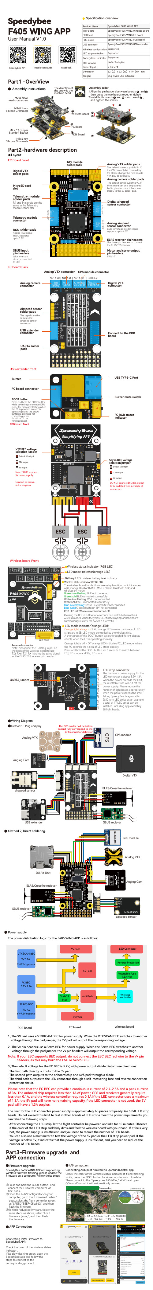
Specification overviewSpeedybeeF405 WING APPPart1 -OverViewSpeedybee APP Installation guide FacebookAssembly InstructionsM2x4 smallhead cross screwThe direction ofthe arrow is themachine headWireless BoardFC BoardPDB BoardM3x8.1 mmSilicone GrommetsM2 x 12 copperStandoff SpacerM3x4 mmSilicone GrommetsABC1.Align the pin headers between boards andthen press the two boards together tightly.2.Install both boards and onto board ,and tighten the screws.A BA B CAssembly orderABCCFC Board FrontPart2-hardware descriptionLayoutDigital airspeedsensor connectorAnalog VTX solder padsThe default power supply is 9V. Ifthe VTX can only be powered by5V, please change the PDB board'sVTX BEC to output 5V.Telemetry modulesolder padsTelemetry moduleconnectorRS SI sol de r p ad sSBUS inputpin headersMotor and servo outputpin headers MicroSD cardslotDigital VTXsolder padsAnalog camera solder padsAnalog airspeedsensor connectorELRS receiver pin headers same asthe Telemetrymodule connectorAnalog RSSI signalinput, supportsup to 3.3VWith inversioncircuit, connectedto RX2PWM1-11The default power supply is 9V. Ifthe camera can only be poweredby 5V, please connect the powersupply to the 5V solder pad.Built-in voltage divider circuit,supports up to 6.6V.Use these pin headers to connectthe ELRS/TBS receiver.GPS moduleFC Board BackSH1.0 6PAnalog cameraconnectorGPS module connectorAirspeed sensorsolder padsUSB extenderconnectorDigital VTXconnectorConnect to the PDBboardUART6 solderpadsVTXT G9VNCCAMGND9VSBUSGNDRX5TX5G9SDASCL4V5G T RSH1.0 4PThe signals are thesame as theairspeed sensorconnector.Analog VTX connectorUSB extender frontBuzzer USB TYPE-C PortBuzzer mute switchoperating state, the BOOTbutton is also used forcontrolling otherfunctions of thewireless board.FC RGB statusindicator BOOT buttonFC board connectorPDB board FrontConnect as shownin the diagramNote: TX800 requires5V power supply.VTX BEC voltageselection jumperServo BEC voltageselection jumper 12V outputDefault 9V output5V output6V outputDefault 5V output7.2V outputDO NOT connect ESC BEC outputto Vx pad (Red wire in middle ofconnector).4-level battery level indicator.Note: disconnect the UART6 jumper onthe back of the wireless board to useTX6 RX6. TX1 RX1 shares the same signalas the ELRS/TBS receiver pin header.Wireless status indicator (RGB LED)LED mode indicator(orange LED):, and Wireless board FrontLED mode indicator(orange LED)Battery LED:BLE not connectedGreen solid:BLE connected successfullyWhite slow flashing :Wi-Fi not connectedWhite Solid:Wi-Fi connected successfullyBlue slow flashing:Classic Bluetooth SPP not connectedBlue Solid:Classic Bluetooth SPP not connectedRGB LED off: Wireless module turned offPressing the BOOT button for 6 seconds can switch between the 4wireless modes. When the yellow LED flashes rapidly and the boardautomatically restarts, the switch is successful.Orange light always on:Solid orange LED means the 4 sets of LEDstrips are in SB_LED mode, controlled by the wireless chip.A short press of the BOOT button cycles through different displayeffects when the FC is operating normally.Orange light is off - Off orange LED indicates FC_LED mode, wherethe FC controls the 4 sets of LED strips directly.Press and hold the BOOT button for 3 seconds to switch betweenFC_LED mode and SB_LED mode.The maximum power supply for theLED connector is about 5.2V 1.3A.When the power exceeds the limit,the resettable fuse will cut off thepower supply. Please reduce thenumber of light beads appropriatelywhen the power exceeds the limit.Taking SpeedyBee Programable2812 Arm LED strips as an example,a total of 17 LED strips can beinstalled, including approximately68 light beads.LED strip connectorUART6 jumperSH1.0 3PSH1.0 3PSH1.0 3PWiring DiagramUSB extenderSR ST4S2S1VX VX4V5G G GGGGGGGVXVXVXVXVXVXS3S4S5S6S7S8SR14V5GND5VT4R4G8I428P7AA12203T E L EM2/4Wireless boardFC boardPDB boardPower supplyThe power distribution logic for the F405 WING APP is as follows:1、 The 9V pad uses a VTX&CAM BEC for power supply. When the VTX&CAM BEC switches to another voltage through the pad jumper, the 9V pad will output the corresponding voltage.2、The Vx pin headers use a Servo BEC for power supply. When the Servo BEC switches to anothervoltage through the pad jumper, the Vx pin headers will output the corresponding voltage.3、The default voltage for the FC BEC is 5.2V, with power output divided into three directions:·The first path directly outputs to the 5V pad.·The second path outputs to the onboard chip and 4V5 pad through a diode.·The third path outputs to the LED connector through a self-recovering fuse and reverse connection protection circuit.The limit for the LED connector power supply is approximately 68 pieces of SpeedyBee 5050 LED strip beads. Do not exceed this limit.To test if other brands of LED strips meet the power requirements, you can take the following steps:·After connecting the LED strip, let the flight controller be powered and idle for 10 minutes. Observe if the color of the LED strip suddenly dims and feel the wireless board with your hand. If it feels very hot, the power supply is insufficient, and you need to reduce the number of LED beads.·You can also use a multimeter to test the voltage of the 5V pad or the LED strip power pad. If thevoltage is below 5V, it indicates that the power supply is insufficient, and you need to reduce thenumber of LED beads.Note: If your ESC supports BEC output, do not connect the ESC BEC red wire to the Vx pinheaders, as this may burn the ESC or Servo BEC.Please note that the FC BEC can provide a continuous current of 2.4-2.5A and a peak current of 3A. The onboard chip requires less than 1A of power, GPS and receivers generally require less than 0.1A, and the wireless controller requires 0.1A.If the LED connector uses a maximum of 1.3A, the 5V pad will have no remaining capacity.If the LED connector is not used, the 5V pad will have a 1.3A surplus.APP connectionPart3-Firmware upgrade andAPP connection①Press and hold the BOOT button , andconnect the FC to the computer viaUSB cable.②Open the INAV Configurator on yourcomputer, go to the "Firmware Flasher "page, select the flight controller targetas "SPEEDYBEEF405WING", and thenflash the firmware.③To flash Ardupilot firmware, follow thesame steps as above, select "LoadFirmware [local]", and then flashthe firmware.SpeedyBee F405 WING APP not supportingwireless firmware flashing, please update thefirmware on a computer. Follow these steps:Check the color of the wireless status indicator. If it's not flashingwhite, press the BOOT button for 6 seconds to switch to white.Then connect to the "Speedybee F405Wing" Wi-Fi and openQGroundControl, it will automatically connect.Firmware upgradeConnecting Ardupilot firmware to QGroundControl app.Check the color of the wireless statusindicator .If it's slow flashing green, open theSpeedyBee app and follow thesteps to connect to thecorresponding product.Connecting INAV Firmware toSpeedybee APP.23APP ConnectionSuitable for different flight control firmware and Configurator. The supported apps are listed in thefollowing table. It is recommended to use Bluetooth BLE mode for iNav and WiFi mode for Ardupilot.Part4-SpecificationsSpeedyBee F405 WING FC board STM32F405,168MHz,1MB FlashICM-42688-P SPL006-001AT7456EMicroSD Card Slot6 sets(USART1, USART2, USART3, UART4, UART5, UART6(Dedicated for Wireless board Telemetry connection))1x Used for magnetometer, digital airspeed sensor 4x (VBAT, Current, RSSI, Analog AirSpeed)12x (11+1“LED”pad)Supported,connected to UART1Built in inverter for SBUS input (UART2-RX)3x LEDs for FC STATUS (Blue, Green) and 3.3V indicator(Red) 1x RGB Supported,Named as RS .INAV:SpeedyBeeF405WING(default)ArduPilot: SpeedyBeeF405WINGMCUIMU(Gyro&Accelerometer) Barometer OSD Chip Blackbox UART I2C ADC PWMELRS/CRSF receiver SBUS LED RSSISupported FC FirmwareSpeedyBee F405 WING PDB boardInput voltage range Battery Voltage Sensor Battery Current Sensor TVS Protective diode FC BEC outputVTX BEC output OutputServo BEC output 7~36V (2~6S LiPo)Connect to FC board VBAT, 1K:10K (Scale 1100 in iNav, BATT_VOL T_MUL T 11.0 in ArduPilot)90A continuous, 215A peak Connect to FC board Current (Scale 195 in iNav, 50 A/V in ArduPilot)YesOutput 5.2V +/- 0.1V DC Continuous current 2.4 Amps, 3A Peak Designed for FC, Receiver, GPS module, AirSpeed module, Telemetry module, WS2812 LED_StripOutput 9V +/- 0.1V DC Continuous current 1.8 Amps, 2.3A Peak Voltage adjustable, 9V Default, 12V or 5V via jumper Designed for Analog Video Transmitter,Digital Video Transmitter, Camera.Output 4.9V +/- 0.1V DC Continuous current 4.5 Amps, 5.5A PeakVoltage adjustable, 4.9V Default, 6V or 7.2V via jumper Designedfor Servos.BLE mode, connect to Speedybee APPClassic Bluetooth SPP mode, connect to QGroundControl APP , MissionPlanner4x WS2812 LED strip connectors, adjustable colors and flashing modesMax 5.2V 1.3A, supports around 68pcs 5050 WS2812 LED beads4x RGB indicator LED for battery level display by number of lightsWireless Configuration(long press BOOT button for 6 seconds to switch modes)LED strip controller (short press BOOT button to switch effects, long press 3 seconds to switch modes)On-board battery level indicator Wi-Fi mode, connect to QGroundControl APP , Speedybee APP , MissionPlanner, etc.SpeedyBee F405 WING Wireless boardPart5-pin mappingUART USB TX1 RX15V tolerant I/OUART1ELRS/TBS receiverSBUS receiver, SBUS pad = RX2 with inverter SmartPort Telemetry,enable Softserial_Tx2GPS USER DJI OSD/VTXOnboard wireless controllerTX3 RX35V tolerant I/O UART3TX4 RX45V tolerant I/O UART4TX5 RX55V tolerant I/O UART5TX6 RX65V tolerant I/OUART6TX2 RX2SBUS 5V tolerant I/OSBUS padTX2USB INAV mappingPWM TIMER INAV Plane INAV MultiRotor S1TIM4_CH2Motor Motor 5V tolerant I/O S2TIM4_CH1Motor Motor 5V tolerant I/O S3TIM3_CH3Servo Motor 5V tolerant I/O S4TIM3_CH4Servo Motor 5V tolerant I/O S5TIM8_CH3Servo Motor 5V tolerant I/O S6TIM8_CH4Servo Motor 5V tolerant I/O S7TIM8_CH2N Servo Servo 5V tolerant I/O S8TIM2_CH Servo Servo 5V tolerant I/O S9TIM2_CH4Servo Servo 5V tolerant I/O S10TIM2_CH1Servo Servo 5V tolerant I/O S11TIM12_CH2Servo Servo 5V tolerant I/O LEDTIM1_CH1WS2812LEDWS2812LED5V tolerant I/OADCVBAT CURR AIRSPD RSSIVBAT ADCADC_CHANNEL_1CURRENT_METER ADC ADC_CHANNEL_2AIRSPEED ADC ADC_CHANNEL_3RSSI ADCADC_CHANNEL_4voltage scale 11001K:10K divider builtin 0~30V 0~3.3V10K:10K divider builtin 0~6.6V 0~3.3VCurrent scale 195Analog Airspeed Analog RSSII2CI2C1onboard BarometerCompassDigital Airspeed sensor OLEDSPL06-001QMC5883 / HMC5883 /MAG3110 / LIS3MDL MS45250.96″5V tolerant I/OArduPilot mappingUSB TX1 RX1TX2 RX2SBUSTX3 RX3TX4 RX4TX5 RX5TX6 RX6USBUSART1(With DMA)SBUS pad RX2USART2USART3UART4UART5USART6SERIAL0SERIAL1BRD_AL T_CONFIG 0DefaultBRD_AL T_CONFIG 1SERIAL2SERIAL3SERIAL4SERIAL5SERIAL6ConsoleELRS/TBS receiver Serial RC inputSBUS receiver,SBUS pad = RX2 with inverter IBUS/DSM/PPM USER GPS1USER DJI OSD/VTX Telem1*If sending highspeed serial data (eg. 921600 baud) to the board, use USART1(Serial1).PWM S1S2S3S4S5S6S7S8S9S10S11LEDPWM1 GPIO50PWM2 GPIO51PWM3 GPIO52PWM4 GPIO53PWM5 GPIO54PWM6 GPIO55PWM7 GPIO56PWM8 GPIO57PWM9 GPIO58PWM10 GPIO59PWM11 GPIO60PWM12 GPIO61TIMER TIM4_CH2TIM4_CH1TIM3_CH3TIM3_CH4TIM8_CH3TIM8_CH4TIM8_CH2N TIM2_CH3TIM2_CH4TIM2_CH1TIM1_CH3N TIM1_CH1PWM/DShot(DMA)PWM/DShot(DMA)PWM/DShot(DMA)PWM/DShot(DMA)PWM/DShot(DMA)PWM/DShot(DMA)PWM/DShot(DMA)PWM/DShot(DMA)PWM/DShot(DMA)PWM/DShot(DMA)PWM/DShot(DMA)PWM/DShot(DMA)Group1Group2Group3Group4Group5*All motor/servo outputs are DShot and PWM capable. However, mixing DShot and normal PWM operation for outputs is restricted into groups, ie. enabling DShot for an output in a group requires that ALL outputs in that group be configured and used as DShot, rather than PWM outputs. LED, which corresponds to PWM12, is set as the default output for NeoPixel1. Therefore, if you need to use PWM11 as an output, you need to disable the NeoPixel1 function on PWM12.ADCVBATCURRAIRSPDRSSIBattery voltageCurrent senseAnalog AirspeedAnalog RSSIBATT_VOL T_PINBATT_VOL T_MUL TBATT_CURR_PINBATT_AMP_PERVL TARSPD_ANA_PINARSPD_TYPERSSI_ANA_PINRSSI_TYPE1011.051150152142 1K:10K divider builtin0~30V0~3.3V10K:10K divider builtin0~6.6V0~3.3VI2CI2C1onboard BarometerCompassDigital Airspeed sensorMS4525ASP5033SPL06-001COMPASS_AUTODECARSPD_BUSARSPD_TYPEARSPD_TYPE115 5V tolerant I/OPart7-PackageM2x4 small head4pin Dupont single-headCable(150mm) x18pin SH1.0 USB4pin SH1.0 to 3+2pin JST1.25 FPV CamCable(250mm) x1。

智慧停车系统错误405设计方案设计方案:智慧停车系统错误4051. 问题分析错误405通常表示请求的HTTP方法不被服务器支持。
在智慧停车系统中,错误405可能是由于以下原因导致的:- 请求使用了不被系统支持的HTTP方法,例如GET请求实际需要使用POST方法;- 请求的URL路径错误,导致服务器无法找到对应的处理接口;- 系统服务端处理程序出现问题,无法正确解析请求;2. 解决方案为了解决智慧停车系统中的错误405问题,可以采取以下措施:- 检查请求方法:对于接收到的请求,首先需要验证所使用的HTTP方法是否正确。
如果HTTP方法错误,需要返回适当的错误响应,并提供正确的方法信息;- 检查URL路径:在服务器端,需要对接收到的URL 路径进行验证,确保服务器能够找到对应的处理程序。
如果请求的URL路径错误,需要返回适当的错误响应,并提供正确的URL路径信息;- 检查处理程序:对于正确的请求方法和URL路径,服务器需要确保能够正确解析请求并提供相应的处理。
如果处理程序出现问题,需要返回适当的错误响应,并提供错误信息;- 记录错误日志:对于错误405,服务器端应该记录相关错误信息,以便分析错误产生的原因,并进行问题排查。
错误日志可以记录请求信息、出错时间、出错位置等关键信息,以便开发人员准确定位问题;- 客户端优化:对于智慧停车系统的客户端,可以通过错误405的返回信息进行优化。
客户端需要能够正确解析错误信息,并提供给用户友好的提示和建议;- 定期更新系统:智慧停车系统应该定期进行更新,以修复已知的错误和漏洞。
更新过程中,要特别注意对错误405进行修复,确保系统能够正常处理各类请求。
3. 测试和优化在解决错误405的方案实施过程中,需要进行相应的测试和优化:- 单元测试:对于处理程序的实现,需要进行单元测试,以保证其能够正确解析各类请求,并返回正确的响应;- 集成测试:对于整个智慧停车系统,需要进行集成测试,确保各个组件之间能够正确协作,处理不同类型的请求;- 压力测试:对于系统的性能和稳定性,需要进行压力测试,模拟系统在高负载情况下的表现,并确保系统能够正常处理请求;- 用户反馈和优化:在实际使用中,用户可能会遇到错误405或其他问题。

GCAN-4055CANopen接口DI/DO数据采集模块用户手册文档版本:V3.20(2018/07/18)修订历史版本日期原因V1.002013/06/16创建文档V2.012013/12/20修正设备工作参数V3.012014/10/22添加部分参数V3.022017/04/11修改部分参数V3.072017/06/17修改部分描述及参数V3.102018/04/02添加关于节点保护的描述V3.202018/07/18调整文档结构目录1功能简介 (4)1.1功能概述 (4)1.2性能特点 (4)1.3典型应用 (4)1.4原理框图 (4)2设备安装 (6)2.1设备尺寸 (6)2.2接口定义及功能 (6)3设备使用 (9)3.1电源连接 (9)3.2与CAN-bus连接 (9)3.3CAN总线终端电阻 (10)3.4系统状态指示灯 (10)4配置说明 (12)4.1CAN节点号配置 (12)4.2CAN波特率配置 (12)5通讯报文格式 (14)5.1节点状态 (14)5.2NMT命令 (14)5.3PDO命令 (16)5.4SDO命令 (18)6GCAN-4055对象字典 (21)7使用注意 (24)8技术规格 (25)附录A:CAN2.0A协议帧格式 (26)附录B:CANopen协议简介 (27)附录C:数字量输入输出说明 (34)1数字量输入 (34)2数字量输出 (37)1功能简介1.1功能概述GCAN-4055模块是集成1路标准CANopen接口、8路开关量输入通道、8路开关量输出通道的工业级CANopen数字量输入输出模块。
采用GCAN-4055模块,用户可用于采集数字量输入信号,并输出数字量信号,控制开关,实现远程开关设备和CANopen网络之间的连接,构成CANopen网络中数据量信号采集、输出的控制节点。
GCAN-4055模块是数字量信号采集和输出的关键性工具,同时该模块具有体积小巧、接线便捷等特点。
说明:ADAM-4055只支持MODBUS的01、05功能码,不支持03、06功能码。
1、ADAM-4055的+Vs、GND脚接DC10V~DC30V开关电源。
计算机串口通过“RS232-RS485转换器”和ADAM-4055的DATA+、DATA-连接。
ADAM-4055的INIT*脚接到GND脚。
2、打开“Adam-4000-5000 Utility”软件点“Search”找到ADAM-4055,在Address 设适当地址,在Protocol选Modbus,把Timeout Setting改成保护时间,如一厂虹吸滤池一般整个洗池过程不会超过一个小时所以可以设成3600 Sec。
然后Update。
3、断电并解掉INIT*脚与GND脚的连线。
补充说明:断电输出点将会复位。
读:DI0:01 01 00 00 00 01 FD CA 从站地址功能码源地址个数读:DI0~DI1:01 01 00 00 00 02 BD CB读:DI0~DI7 01 01 00 00 00 08 3D CC读:DO0~DO7 01 01 00 10 00 08 3C 09开DO0:01 05 00 10 FF 00 8D FF从站地址功能码目标地址(N11:235) 数据(N10:216)开DO1:01 05 00 11 FF 00 DC 3F开DO2:01 05 00 12 FF 00 2C 3F开DO3:01 05 00 13 FF 00 7D FF开DO4:01 05 00 14 FF 00 CC 3E开DO5:01 05 00 15 FF 00 9D FE开DO6:01 05 00 16 FF 00 6D FE开DO7:01 05 00 17 FF 00 3C 3E关DO0:01 05 00 10 00 00 CC 0F关DO1:01 05 00 11 00 00 9D CF关DO2:01 05 00 12 00 00 6D CF关DO3:01 05 00 13 00 00 3C 0F关DO4:01 05 00 14 00 00 8D CE关DO5:01 05 00 15 00 00 DC 0E关DO6:01 05 00 16 00 00 2C 0E。
VAR-SOM-MX8M-PLUS based on NXP i.MX 8M PlusEvaluation Kit Quick Start GuideFeatures:1. Power ON Switch (SW7)2. 12V DC In Jack (J24)3. USB Debug (J29)4. micro SD Card slot (J28)5. USB 3.0 OTG (J26)6. USB 2.0 Host (J23)7. Gigabit Ethernet #0 (J21) 8. Gigabit Ethernet #1 (J20)9. MIPI-CSI #1 Camera connector [optional] (J19) 10. Miscellaneous Header #1 (J17)11. HDMI/ MIPI-CSI #2 Camera connector[optional] (J13)12. Mini PCI Express Connector (J15) 13. Miscellaneous Header #2 (J3) 14. SOM Connector (J1) 15. LVDS#B Header (J5)16. LVDS#A/ DSI Header (J7) 17. Fan Power Connector (J9) 18. Digital Microphone (U1) 19. Resistive Touch (J10) 20. Capacitive Touch (J11)21. User Buttons (SW1, SW2, SW4) 22. Line-In Connector (J12)23. Headphones Connector (J14) 24. Boot Select Switch (SW3)25. SAI/I2C/SPI/CAN Header (J16) 26. Reset Button (SW5)27. PWR Select Switch (SW6) 28. UART/PWM Header (J18) 29. RTC Battery Holder (JBT1)Evaluation kit initial Setup1. Carefully remove the 7” LCD and Symphony-Board from the package.2. Connect the 7” LCD Display and Touch cablesto the Evaluation Kit connectors J7, J11 respectively.Note:connect the display cable with the red wire on pin 1. Connect the touch cable with the metal contacts facing down.3. Plug the USB type A to micro B cable betweenthe USB debug connector (J29) and a PC USB port.4. For heatsink assembly instructions, pleasefollow the VHP-VS8M documentation .Please note that the heatsink is mainly used for CPU/GPU intensive applications and may be required per your specific use case.P/N VSS0177AVAR-SOM-MX8M-PLUS based on NXP i.MX 8M PlusEvaluation Kit Quick Start GuideSetting the host PC for debug1. Download any PC terminal software (e.g. Putty ).2. Set the PC terminal software parameters as follows:- Baud Rate: 115200 - Data bits: 8 - Stop bits: 1 - Parity: None- Flow Control: NoneBooting from eMMC1. Set Boot select switch (SW3) to “Internal” position to boot from the VAR-SOM-MX8M-PLUS internal storage.2. Plug the wall adapter into the 12V power jack (J24) and to a 120VAC~240VAC power source.3. Set Power ON switch (SW7) to ON state.4. Boot messages are printed within the PC terminal window.Booting from a micro SD cardThe microSD card is supplied within the package. Updated SD card images can also be downloaded from the Variscite FTP server.See more details in the recovery SD card section in the Variscite Wiki pages.1. Set Power ON switch (SW7) to off state.2. Set Boot select switch (SW3) to “SD ” positionin order to boot from SD Card.3. Push microSD card into the microSD cardslot (J28) of the Symphony-Board.4. Set Power ON switch (SW7) to ON state.5. Boot messages are print ed within PC’sterminal window.(Re-)Installing the file system to eMMCPlease refer to the recovery SD card section in the Variscite Wiki pages.Linkso Wiki page:https:///index.php?title=VAR-SOM-MX8M-PLUSo VAR-SOM-MX8M-PLUS Evaluation kits:https:///product/evaluation-kits/var-som-mx8m-plus-evaluation-kits/o VAR-SOM-MX8M-PLUS System on Module:https:///product/system-on-module-som/cortex-a53-krait/var-som-mx8m-plus-nxp-i-mx-8m-plus/o Symphony carrier board:https:///product/single-board-computers/symphony-board/o Customer portal:https:///loginThank you for purchasing Variscite’s product.For additional assistance please contact: *******************。
UC-5100系列Arm Cortex-A81GHz IIoT閘道器,配備1個無線模組的mini PCIe擴充插槽、4個串列連接埠、2個CAN連接埠、4個DI、4個DO特色與優點•Armv7Cortex-A81000Mhz處理器•雙自動感應10/100Mbps乙太網路連接埠•4個RS-232/422/485連接埠,可透過軟體選擇,支援所有訊號•支援工業CAN2.0A/B通訊協定的雙CAN連接埠•Moxa Industrial Linux,提供10年長期支援•適用於Wi-Fi/行動通訊模組的Mini PCIe插槽•用於儲存裝置擴充的SD卡插槽•-40至85°C寬溫度範圍,啟用LTE時溫度為-40至70°C•適用於嚴苛工業環境的IEC61000-6-2/6-4標準認證簡介UC-5100系列嵌入式電腦專為工業自動化應用而設計。
具有輕巧的外形,所有插槽均置於前面板,包括4個可調整上拉/下拉電阻的RS-232/422/485全信號串列連接埠、2個CAN連接埠、2個乙太網路連接埠、4個DI通道、4個DO通道、USB介面和SD插槽。
為了滿足各種工業應用,UC-5100系列運算平台提供的型號配備2個CAN連接埠和用於無線連線的mini PCIe插槽,以及用於網路備援的雙SIM設計。
UC-5100的垂直DIN軌道機殼很容易就能將電腦安裝在小型機櫃中。
這套解決方案不但節省空間,而且易於佈線,使UC-5100成為工業應用前端嵌入式控制器的絕佳選擇。
此外,所有型號均配備Moxa Industrial Linux,提供長達10年的支援服務和經最佳化的軟體特性。
外觀UC-5101UC-5102UC-5111UC-5112規格ComputerCPU Armv7Cortex-A81GHzPre-installed OS Linux Debian9kernel4.4(Moxa Industrial Linux) DRAM512MB DDR3Storage Pre-installed8GB eMMCStorage Slot SD slots x1Expansion Slots UC-5102-LX:mPCIe slots x1UC-5112-LX:mPCIe slots x1UC-5102-T-LX:mPCIe slots x1UC-5112-T-LX:mPCIe slots x1Computer InterfaceUSB2.0USB2.0hosts x1,type-A connectorsNumber of SIMs2SIM Format MicroSerial Ports RS-232/422/485ports x4,software selectable(RJ45)Digital Input DIs x4Digital Output DOs x4Buttons Reset button,DIP switch for serial and CAN port configuration Console Port RS-232(TxD,RxD,GND),RJ45output(115200,n,8,1) Ethernet InterfaceEthernet Ports Auto-sensing10/100Mbps ports(RJ45connector)x2 Magnetic Isolation Protection 1.5kV(built-in)Serial InterfaceSerial Ports4x RS-232/422/485Data Bits5,6,7,8Parity None,Even,Odd,Space,MarkStop Bits1,1.5,2Serial SignalsRS-232TxD,RxD,RTS,CTS,DTR,DSR,DCD,GNDRS-422Tx+,Tx-,Rx+,Rx-,GNDRS-485-2w Data+,Data-,GNDRS-485-4w Tx+,Tx-,Rx+,Rx-,GNDCAN InterfaceNo.of Ports UC-5111-LX:2UC-5111-T-LX:2UC-5112-LX:2UC-5112-T-LX:2Signals UC-5111-LX:CAN_L,CAN_H,CAN Signal GNDUC-5111-T-LX:CAN_L,CAN_H,CAN Signal GNDUC-5112-LX:CAN_L,CAN_H,CAN Signal GNDUC-5112-T-LX:CAN_L,CAN_H,CAN Signal GND Terminator UC-5111-LX:N/A,120ohms(by DIP)UC-5111-T-LX:N/A,120ohms(by DIP)UC-5112-LX:N/A,120ohms(by DIP)UC-5112-T-LX:N/A,120ohms(by DIP)Digital InputsVoltage0to0.8VDC2.0to5.5VDCDigital OutputsCurrent Rating24mA per channelVoltage0to0.55VDC2.5to3.3VDCLED IndicatorsSystem Power x1System Ready x1LAN2per port(10/100Mbps)Serial2per port(Tx,Rx)CAN UC-5111-LX:2per port(Tx,Rx),UC-5112-LX:2per port(Tx,Rx),UC-5111-T-LX:2perport(Tx,Rx),UC-5112-T-LX:2per port(Tx,Rx)Wireless Signal Strength UC-5112-LX:Cellular/Wi-Fi x3UC-5102-LX:Cellular/Wi-Fi x3UC-5102-T-LX:Cellular/Wi-Fi x3UC-5112-T-LX:Cellular/Wi-Fi x3Physical CharacteristicsHousing MetalWeight600g(1.32lb)Dimensions57x136x100mm(2.24x5.35x3.94in)Installation DIN-rail mounting,Wall mounting(with optional kit)Power ParametersInput Voltage9to48VDCInput Current0.95A@9VDC,0.23A@48VDCPower Consumption11WEnvironmental LimitsOperating Temperature Standard Models:-10to60°C(14to140°F)Wide Temp.Models:Product only:-40to85°C(-40to185°F)With LTE accessory:-40to70°C(-40to158°F)With Wi-Fi accessory:-10to70°C(14to158°F)Storage Temperature UC-5101-LX:-20to70°C(-4to158°F)UC-5102-LX:-20to70°C(-4to158°F)UC-5111-LX:-20to70°C(-4to158°F)UC-5112-LX:-20to70°C(-4to158°F)UC-5101-T-LX:-40to85°C(-40to185°F)UC-5102-T-LX:-40to85°C(-40to185°F)UC-5111-T-LX:-40to85°C(-40to185°F)UC-5112-T-LX:-40to85°C(-40to185°F)Ambient Relative Humidity5to95%(non-condensing)Vibration2Grms@IEC60068-2-64,random wave,5-500Hz,1hr per axis(without USB devicesattached)Shock IEC60068-2-27Standards and CertificationsSafety UL60950-1,IEC60950-1,EN62368-1EMC EN55032/24,EN61000-6-2/-6-4EMI CISPR32,FCC Part15B Class AEMS IEC61000-4-2ESD:Contact:6kV;Air:8kVIEC61000-4-3RS:80MHz to1GHz:10V/mIEC61000-4-4EFT:Power:2kV;Signal:1kVIEC61000-4-5Surge:Power:2kV;Signal:2kVIEC61000-4-6CS:10VIEC61000-4-8PFMFGreen Product RoHS,CRoHS,WEEEReliabilityAlert Tools External RTC(real-time clock)Automatic Reboot Trigger External WDT(watchdog timer)MTBFTime UC-5101-LX:728,216hrsUC-5101-T-LX:728,216hrsUC-5102-LX:704,409hrsUC-5102-T-LX:704,409hrsUC-5111-LX:584,470hrsUC-5111-T-LX:584,470hrsUC-5112-LX:568,997hrsUC-5112-T-LX:568,997hrsStandards Telcordia(Bellcore)Standard TR/SR WarrantyWarranty Period5yearsDetails See /tw/warrantyPackage ContentsDevice1x UC-5100Series computer Documentation1x quick installation guide1x warranty cardInstallation Kit1x DIN-rail kit(preinstalled)1x power jackCable1x RJ45-to-DB9console cable尺寸訂購資訊Model Name CPU RAM Storage Ethernet Serial CAN SD USB Mini PCIeOperatingTemp.UC-5101-LX1GHz512MB8GB24–11–-10to60°CUC-5102-LX 1GHz512MB8GB24–111(dual-SIMsocket)-10to60°CUC-5111-LX1GHz512MB8GB24211–-10to60°CUC-5112-LX 1GHz512MB8GB242111(dual-SIMsocket)-10to60°CUC-5101-T-LX1GHz512MB8GB24–11–-40to85°CUC-5102-T-LX 1GHz512MB8GB24–111(dual-SIMsocket)-40to85°CUC-5111-T-LX1GHz512MB8GB24211–-40to85°CUC-5112-T-LX 1GHz512MB8GB242111(dual-SIMsocket)-40to85°C配件(選購)Power AdaptersPWR-12150-USJP-SA-T Locking barrel plug,12VDC1.5A,100to240VAC,United States/Japan(US/JP)plug,-40to75°Coperating temperaturePWR-12150-EU-SA-T Locking barrel plug,12VDC,1.5A,100to240VAC,Continental Europe(EU)plug,-40to75°C operatingtemperaturePWR-12150-UK-SA-T Locking barrel plug,12VDC,1.5A,100to240VAC,United Kingdom(UK)plug,-40to75°C operatingtemperaturePWR-12150-AU-SA-T Locking barrel plug,12VDC,1.5A,100to240VAC,Australia(AU)plug,-40to75°C operatingtemperaturePWR-12150-CN-SA-T Locking barrel plug,12VDC,1.5A,100to240VAC,China(CN)plug,-40to75°C operating temperature Wi-Fi Wireless ModulesUC-WiFi-USB802.11a/b/g/n/ac,2.4/5GHz Wi-Fi module with2each of M2and M2.5screwsCellular Wireless ModulesUC-LTE-CAT1-EU LTE cellular module with2M2and2M2.5mounting screws for EMEA bands1,3,7,8,20,28AUC-LTE-CAT1-AP LTE cellular module with2M2and2M2.5mounting screws for APAC bands1,3,5,8,9,18(26),19,28 UC-LTE-CAT4-CN LTE cellular module with2M2and2M2.5mounting screws for LTE(FDD)bands B1,B3,B8and LTE(TDD)bands B39,B40,B41(38)AntennasANT-WDB-ARM-0202plus ADP 2.4/5GHz omni-directional antenna,2/2dBi,RP-SMA-type(male)connectorANT-LTE-OSM-03-3m BK700-2700MHz,multi-band antenna,specifically designed for2G,3G,and4G applications,3m cable ANT-LTE-ASM-04BK704-960/1710-2620MHz,LTE omni-directional stick antenna,4.5dBiANT-LTE-ASM-05BK704-960/1710-2620MHz,LTE stick antenna,5dBiANT-LTE-OSM-06-3m BK MIMO Multiband antenna with screw-fastened mounting option for700-2700/2400-2500/5150-5850MHzfrequenciesDIN-Rail Mounting KitsDK-UC-5000DIN-rail mounting kit with screws for the UC-5000SeriesWall-Mounting KitsWM-UC-5000Wall-mounting kit with screws for the UC-5000Series©Moxa Inc.版權所有.2021年6月03日更新。
GCAN-212Customized CAN bus converter with CPCI portUser ManualDocument version:V3.11(2017/10/23)Contents1.Introduction (3)1.1Overview (3)1.2Properties at a glance (3)2.Converter used (5)2.1GCAN-212converter Ethernet working mode (5)2.2GCAN-212configuration (5)2.3Connect to Ethernet (5)2.4Connect to CAN-Bus (6)2.5System LED (6)3.TCP protocol format (8)3.1CANopen slave station to Ethernet(RPDO) (8)3.2Ethernet to CANopen slave station(TPDO) (8)3.3Check bit calculation method (9)4.Configuration instructions (10)4.1GCAN-212connection (10)4.2Configuring communication basic information (11)4.3Complete configuration (12)4.4Upgrade the firmware (12)5.Technical specifications (13)1.Introduction1.1OverviewGCAN-212is a customized converter with one or two CAN bus interfaces.The converter has integrated CPCI interface,so it can be used to IPC which communicate through CPCI bus.The GCAN-212can customize multiple communication interfaces such as:Ethernet, Serial bus,USB,and so ers can use the customized converter into their own system and connect it to CAN bus.Note:The following chapter and parameters are all customized to CANopen-Ethernet.1.2Properties at a glance1.2.1Hardware●High-speed32-bit MCU●Built-in FLASH storage,parameters and mapping table can be stored.●Power supply:DC9~30V(40mA,24VDC),others can be customized.●Electrostatic discharge immunity level:contact discharge±6KV,air discharge±15KV●Electrical fast transient burst immunity level:±1KV●Surge immunity level:±1KV●Operating temperature range:-40℃~+85℃●Operating humidity range:5%to95%RH no condensation●PCB Dimensions:160mm*100mm*1.6mm●Meet the relevant standards of shock and vibration in vehicle EN50155●For the power part,the following standards should be met:1.2.2CANopen attribute●Integrated1CAN-Bus interface with standard DB9male head CAN interface with locking device(customized)●CAN-Bus signals include:CAN_H,CAN_L,CAN_GND●CAN-Bus isolation converter insulation voltage:DC1500V●32hardware FIFO receive buffers,the highest received data traffic:8000frames/sec●CAN-Bus supports CANopen protocol(customized),support NMT,PDO,SDO, Heartbeat,Guardlife,SYNC●CAN-Bus baud rates range from5Kbps to1Mbps●CANopen node number supports1~127●CANopen supports8TPDO,8RPDO,2SDO●The node address can be configured by DIP switch1.2.3Ethernet attribute●The PC interface uses standard Ethernet interface.RJ45,support10/100M adaptive●Support static or timeout interrupt function●The connection resource is restored automatically after the network is disconnected●Support protocols include ARP,IP,ICMP,UDP,DHCP,DNS,TCP●Compatible with SOCKET work(TCP server,TCP client),the host computer communication software follows the standard SOCKET rules2.Converter usedGCAN-212can use computer software to configure the basic operation parameters, such as CAN bus baud rate,CANopen node ID,Ethernet IP address,gateway and so on.2.1GCAN-212converter Ethernet working modeGCAN-212converter Ethernet uses standard TCP Server working mode.In this mode, the GCAN-212converter does not automatically connect with other equipment.It can communicate with the client after establishing the TCP connection.The process of establishing communication is shown in figure2.1Figure2.1TCP Server Schematic diagram of mode communication2.2GCAN-212configuration2.2.1Restore factory settingsThe GCAN-212converter's defaults IP:192.168.1.10.If the user has modified the IP and forgot,then it can be reset by using the DIP switch in the device.2.2.2Change PC IP addressPC and GCAN-212IP must be in the same network segment.For example:converter IP:192.168.1.10,PC IP:192.168.1.1.Please note:PC IP cannot be the same as the converter IP.2.3Connect to EthernetThe Ethernet interface of the GCAN-212converter integrates a10/100M adaptive Ethernet chip.The converter conforms to the Ethernet standard protocol specification.2.4Connect to CAN-BusIn practical use,users only need to connect the CAN_H to CAN_H and CAN_L to CAN_L,then communication can be realized.The CAN-Bus network adopts topological structure,only the two furthest terminal need to connect120Ωterminal resistance between CAN_H and CAN_L.For branch connection,its length should not be more than3meters.CAN-Bus nodes connection as shown in figure2.2.Figure2.2CAN-Bus networkNote:CAN-Bus using ordinary twisted pair.The relationship between the bus length and baud rate is shown in Table2.1.Table2.1:table2.5System LEDGCAN-212converter with one SYS indicator,one DAT indicator.More functions are shown in table2.2.Table2.2GCAN-212converter status LEDAfter power on the converter,the SYS indicator light indicates that power is being supplied and the system is initializing;otherwise,it indicates power failure or an error occurred.If the bus has data transmission,DAT indicator will flash.Table2.3Indicator light status of GCAN-2123.TCP protocol format3.1CANopen slave station to Ethernet(RPDO)3.2Ethernet to CANopen slave station(TPDO)3.3Check bit calculation methodThe red data part is cumulative.That is,checksum and=data1+data2+...+data32,if the checksum is greater than255,then take the result of low8bit results.4.Configuration instructions4.1GCAN-212connectionThe software needs to connect to the GCAN-212and fill in the IP address of the converter.If you forget the address,you can reset to the factory settings.Click on the"Connect"connection"Connect"-connect equipment"Upload"-read out the configuration information in the converter "DownLoad"-download the configuration information to the converter Flash "Open"-open and read the configuration information file in the PC "SaveAs"-save the configuration information file to your computer4.2Configuring communication basic informationConnection is successful,click the"UpLoad"to upload the parameters in the device to the computer.Enter the Communication Setting interface,and see the parameters and modify."IP Address Info"-set GCAN-212IP address"GateWay"-set the GCAN-212gateway address"Subnet Mask"-setting the GCAN-212subnet mask"Can Baudrate"--setting baud rate of CAN bus communication"Node ID"-setting the node ID number of the CANopen end"TCP TIME"-set the Ethernet end to send the RxPDO cycle,the unit is Ms. "CAN Baudrate"can set the baud rate of the CAN bus,the corresponding table is as follows:650Kbps720Kbps810Kbps4.3Complete configurationIf any of the parameters change,the corresponding will turn red in the software.Click the"DownLoad"to download the configuration information to the Flash.Note:after downloading,you need to power again,and the new configuration will work.4.4Upgrade the firmwareThis function must be used under guidance.5.Technical specifications。
GCAN-4055CANopen IO(8DI/8DO)User ManualDocument version:V3.07(2017/06/17)Contents1Introduction (3)1.1Overview (3)1.2Properties at a glance (3)2Instruction (4)3Configuration (5)3.1CAN node number configuration (5)Figure3.1CAN node number description (6)3.2CAN baud rate configuration (6)4Connect to converter (7)4.1Power supply (7)4.2Connect to CAN-Bus (7)4.3System LED (7)5Application example (8)5.1 (8)5.1Start command (8)5.2NMT command(Network management) (9)5.3PDO command (10)5.4SDO command (12)6GCAN-4055object dictionary (14)1.1OverviewGCAN-4055is an I/O module that use CANopen protocol to communicate with the controller.The module have8digital input channel and8digital output channel.It is widely used in distributed acquisition and control system.1.2Properties at a glanceGCAN-4055DIP switch and terminal interface definition are shown in figure2.1and figure2.2.As shown in figure2.1,GCAN-4055DIP switch1is reset switch,and switch2-8are the node number setting switch.On the right hand side1-4is the baud rate setting switch.Figure2.1GCAN-4055DIP switchAs shown in figure2.2,the function of GCAN-4055pins are as follows:●V+:Connect power supply(+10V~+30V DC)●V-:Connect power negative●PE:Shield●CAN_L:CAN_L●CAN_H:CAN_H●CAN_PE:CAN Shield●CAN_GND:CAN_GND●DI_COM:Dry contact input signal reference●DI_GND:Wet contact input grounding●DI_0~DI7:Dry/Wet contact input●DO_GND:Digital output GND●DO_0~DO7:Digital outputFigure2.2GCAN-4055port3ConfigurationUsers can set the node number and baud rate of GCAN-4055using the DIP switch. Please note:The new parameters will not take effect until the converter power on again.3.1CAN node number configurationAs shown in figure3.1,the user will set the DIP switch to"ON",bit is"1",set to "OFF",bit is"0".The DIP switch2-8can set node ID,the eighth is the lowest bit, the second is highest bit.The node ID is the sum of the decimal values.node ID has a valid range of0~127.Please note:The first switch default is off,please do not change it.Figure3.1CAN node number description3.2CAN baud rate configuration1-4of the right DIP switch can set baud rate.The following table is shown in table 3.2.Table3.2CAN baud rate configuration4Connect to converter4.1Power supplyGCAN-4055support+9-30V DC power supply.We recommend to use12V or24V DC voltage-stabilized power supply.4.2Connect to CAN-BusIn practical use,connecting the CAN_H to CAN_H and CAN_L to CAN_L,then communication can be realized.Note:The CAN-Bus network adopts topological structure,only the two furthest terminal need to connect120Ωterminal resistance between CAN_H and CAN_L.See figure3.2.Figure3.2CAN-Bus network4.3System LEDGCAN-4055has one PWR indicator,one COM indicator,one CAN indicator to indicate the converter status.More functions are shown in table3.2.5Application exampleNote:All slave station in this chapter are set to1.This chapter will use USBCAN-II Pro converter and ECANTools software to receive and transmit CAN-Bus data.You are welcome to purchase it through contact information in the last page of this manual.You can connect USBCAN-II Pro converter CAN1channel to the CAN-Bus channel of GCAN-4055.Then open the ECANTools software and select the correct baud rate.5.1Node statusThe GCAN-4055module meets the standard CANopen CiA301agreement,which is the standard CANopen slave station.After starting the GCAN-4055,it will send out a frame of data to the master station.The frame ID is0x700+Node ID(such as0x701), the cycle time is1second(object dictionary0x100C,node guard time).As shown in figure5.1,this data can be received using the ECANTools software.In the startup data,the first byte of the frame data is the Node state values.0x04means the node is stopped,0x05means the node is operating state,0x7F means the node is in a pre-operational state.Figure5.1Start monitoring interface.5.2Start commandGCAN-4055will send one frame to master station.Frame ID is0x700+Node ID(X).Length of the data is1.Frame data is0x00.For example,GCAN-4055will automatically send a data when it starts. USBCAN-II Pro converter can receive this data and display it,as shown in figure5.2.Figure5.2starts the command5.3NMT command(Network management)Users can use the NMT command of CANopen master station or manually simulate the CANopen protocol to control the GCAN-4055to start or stop.Manual simulation of CANopen protocol start up module data is shown in the following table.Figure5.3NMT start up command5.4PDO commandTPDO1of GCAN-4055is used to indicate the state of input and output.Each of them is represented by one byte.RPDO1is used to change the state of digital output.It is controlled by one byte.5.4.1RPDO command(RPDO1,send by the master station)Users can send data using CANopen master station or manual simulation.You can set the output status of GCAN-4055module.Frame ID is0x200+Node ID(X).Length of the data is1.The first byte of the frame data is used to set output state,each bit set to 1represents output,0represents no output.state is no output.You can send the data as shown in the table below and figure3in figure5.4.GCAN-4055receives the data as shown in the table of the third data in figure 5.5.5.4.2TPDO command (TPDO1,send by GCAN-4055)GCAN-4055uses TPDO to send the current input and output status.Frame ID is 0x180+Node ID (X).The data length is 2.The first byte is the input state,and the second byte is the output state.Each bit is 1represents input/output,0represents no input/output.GCAN-4055has two kinds of TPDO transmission modes.Trigger mode and circulation mode.Default is trigger mode,in this mode,only when DI or DO changes,GCAN-4055will send TPDO data.In the circulation mode,GCAN-4055sends out a TPDO data every 100ms (Cycle time can be changed).Show the state of DI and DO at that time.DO states are no output.GCAN-4055sends the data as shown in the table below and the fourth data in figure 5.5.00 000000000800000100-Figure5.5PDO command monitoring interface5.5SDO commandThe user can send the SDO instructions to modify the TPDO transmission mode of GCAN-4055through the CANopen master station or manual simulation.There are two types of work modes that can be set-trigger mode(default)and circulation mode.5.5.1Circular pattern configurationThe circulation mode is shown in figure5.6.After entering the circulation mode, GCAN-4055sends TPDO to master station every once in a while.Setting method:①Get GCAN-4055into the pre-operational state(see5.3).②Send a frame ID of601to GCAN-4055,frame data is2F001802FE000000. The frame ID of the reply of GCAN-4055will be581after successful delivery,the frame data is60001802XX XX XX.This indicates that the change is successful.③Send the Start remote node(see5.3)to start the converter,GCAN-4055sends one TPDO data every100ms(by default).This is the success of the configuration circulation pattern.Note:If you need to change the interval time of the circulation mode.After the second step,Send frame ID601to GCAN-4055.The frame data is2F002001 XX000000.The red part is the change in the time interval(Hexadecimal), maximum FF,unit ms.Figure5.6the SDO command monitoring interface5.5.2Trigger mode configuration specification(default mode)The trigger mode is shown in figure5.7,GCAN-4055only sends TPDO to master station when IO is changed.Setting method:①Get the GCAN-4055into the pre-operational state(see5.3).②Send the frame ID to the converter601,and the frame data is2F001802FF00 0000.The frame ID of the module response will be581after the successful delivery, and the frame data will be60001802XX XX XX.③After setting success,send the start remote node(see5.3)to start the converter. The converter only sends a TPDO data indicating that the configured circulation mode is successful.6GCAN-4055object dictionaryCommunication parameter area0x1000-Device Type UINT32RO 0x00004055Device type 0x1001Error Register UINT8RO 0Current error type0x10030number of errorsUINT8RO 0-1~4standard error field UINT32RO 0Historical emergency errorcode 0x1005-COB-ID SYNC UINT32RW 0x00000080-0x1006Communication Cycle Period UINT16RW 0x2710Communication cycle0x1007Sync WindowsLength UINT32RW 0-0x1008Manufacturer device name STRIN G CONST GCTech Device name 0x1009Manufacturer hardware version STRIN G CONST 2.0Hardware version 0x100A Manufacturer software version STRIN G CONST 2.0Software version0x100C Guard Time UINT16RW 0x038E -0x100D Life Time FactorUINT8RW 3-0x1017Producer Heartbeat Time UINT16RW 0-0x10180number of Entries UINT8RO 0x04-1Vendor-ID UINT32RO 0x00000001-2Product code UINT32RO 0101Product code 3Revision number UINT32RO 0x00000000Revised code 4Serial numberUINT32RO0x00000001Sequence codeRPDO communication parameters0x1400Highest sub-indexsupported UINT8CONST 1-1COB-ID used byRPDOUINT32RW Node ID+0x80000200RPDO COB-ID0x14010Highest sub-indexsupported UINT8CONST 0-0x14020Highest sub-indexsupported UINT8CONST 0-0x14030Highest sub-indexsupported UINT8CONST 0-0x1600number of mappedUINT8RW1-objects 11st applicationobjectUINT32RW 0x30010008Map 8DO to RXPDO10x16010number of mappedobjectsUINT8RW 0-0x16020number of mappedobjectsUINT8RW 0-0x1603number of mappedobjectsUINT8RW-TPDO communication parameters0x18000Highest sub-indexsupported UINT8CONST 2-1COB-ID used byTPDOUINT32RWNODEID+0x80000180TPDO COB-ID2transmission type UINT8RW0xFF (255)Transport type.0xFF is the trigger mode,0xFE is thecirculation mode,and thecirculation mode deadline is set in index 0x20000x18010Highest sub-indexsupported UINT8CONST 0-0x18020Highest sub-indexsupported UINT8CONST 0-0x18030Highest sub-indexsupported UINT8CONST 0-0x1A000number of mappedobjects UINT8RW 212nd applicationobject UINT32RW 0x30000008Map 8DI to RXPDO123rd applicationobjectUINT32RW 0x30010008Map 8DO to TXPDO10x1A010number of mappedobjectsUINT8RW 00x1A020number of mappedobjectsUINT8RW 00x1A03number of mappedobjectsUINT8RWEquipment state0x20000Set TXPDOinhibit time UINT8RO0x01Set the TXPDO deadline1TPDO1inhibittime UINT8RW100TPDO1inhibit time is ms0x30008DI UINT8RO08input address 0x30018DO UINT8RW08output address。