JKC流量控制器说明书
- 格式:pdf
- 大小:247.17 KB
- 文档页数:7

.word可编辑.一、简介JK-B、JK-C、JK-C1、JK-C2型多时段定时式智能多相位信号控制仪是由南昌金科交通科技股份有限公司开发研制的,符合GB/T25280-2010标准,该系列产品针对各种繁忙路口和复杂的交通流量下的车辆及行人进行通行控制,运用单片机及I2C总线技术进行控制,采用工业级CPU,软硬件看门狗技术使控制仪能在各种恶劣条件下正常工作。
硬件设计将控制仪电源与输出负载电源分离,当负载回路发生短路故障时,能自动断开输出回路,并有指示灯指示。
使用先进的软件设计思路,简便易行的操作方法,能方便实现对28路(JK-B)、44路(JK-C、JK-C1、JK-C2)输出控制。
JK-B型信号机一般多用于机动四灯、五灯的控制上,JK-C、JK-C1、JK-C2型信号机较适用于多车道箭头灯控制上。
二、功能特点⏹保护功能。
当外界电网波动引起电压、电流过大或信号输出严重短路故障,超出信号机承受能力时,本机自动断开强电,使本身得到保护,而控制线路继续工作,同时,面板上保护指示灯亮,通知用户查明故障原因。
⏹四种运行模式,分别为平日、双休、假日、临时,每种模式下最多可设置十个时段,每个时段内最多可设置八个相位。
⏹信号机停电后继续自动走时,并可保持设定好的数据在十年以内的时间不丢失。
⏹如遇紧急情况,可以手动强制通行。
⏹内设硬件、软件看门狗技术。
⏹可设置夜间黄闪和信号灯全部关闭功能。
⏹在信号灯转换时,可设置绿闪、红闪、红黄同亮三种转换模式。
⏹面板模拟路口运行,车道及人行道显示,六位LED数码管构成友好人机对话界面。
⏹十六个工作指示灯,显示控制器运行状态,十一个按键采用先进设计思想,操作灵活简便,功能强大。
⏹具有故障检测功能,可以检测红绿灯故障、是否有绿冲突。
(JK-C2型)⏹带有外接手控操作面板接口,方便手控操作。
(JK-C1型)⏹带有实时倒计时通讯接口,提高倒计时显示的准确性、及时性。
(JK-C1型)⏹全金属外壳,防尘、防电磁干扰、耐用、可靠性好。

replaces 01166/09 GBCompact automatic flow rate regulator with polymer cartridgeFunctionAUTOFLOW ® devices are automatic flow rate regulators capable of keeping the medium flow rate constant as the operating conditions of the hydraulic circuit change. They are used to automatically balance the hydraulic circuit, guaranteeing the design flow rate to each terminal.This series of devices is fitted with a replaceable regulating element, made of high-resistance, scale-resistant and low-noise polymer, for specific use in the circuits of heating and cooling systems and domestic water systems.This particular AUTOFLOW ® series is also supplied with a compact, small valve body for easy installation on individual terminals or in areas of the system.PATENT.Product range127 series Compact automatic flow rate regulator with polymer cartridgesizes 1/2", 3/4”, 1”, 1 1/4", 1 1/2” and 2”Technical specifications Materials Body:brass EN 12164 CW614NAUTOFLOW ® cartridge: - 1/2”–1 1/4”: high-resistance polymer - 1 1/2”–2”: high-resistance polymer and stainless steelSpring:stainless steelSeals:EPDMPerformance Medium:water, glycol solutionsMax. percentage of glycol: 50 %Maximum working pressure: 16 bar Working temperature range: 0–100 °C Δp range: 0,02–0,06 m 3/h: 20–200 kPa 0,085–11 m 3/h: 15–200 kPa Flow rates:0,02–11 m 3/hAccuracy: 0,02–0,06 m 3/h: ±15 % 0,085–11 m 3/h:±10 %Connections:1/2"–2" FDimensionsCircuit balanced with AUTOFLOW ®AUTOFLOW ® devices balance the hydraulic circuit automatically, ensuring that each terminal receives the design flow rate.Even when the regulating valves close the circuit partially, the flow rates in the open circuits remain constant at the nominal value .The system always guarantees the greatest comfort and the highest energy savings.Modern heating and cooling systems have to guarantee a high level of thermal comfort with a low consumption of energy. This means supplying the system terminals with the correct design flow rates, to produce balanced hydraulic circuits.Circuits balanced with manual valvesTraditionally, hydrauliccircuits are balanced using manual setting valves.With these static devices, such circuits are difficult to balance perfectly and have operating limitations when the regulating valves are partially closed. The flow rate in the open circuits does not remain constant at the nominal value .Unbalanced circuitsn unbalanced circuits, the hydraulic imbalance between terminals creates areas with non-uniform temperatures, resulting in problems with thermal comfort and higher energy consumption.Circuit balanci ngFunctionThe AUTOFLOW® device must guarantee a constant flow rate when the upstream/downstream differential pressure varies.t is therefore necessary to refer to the Δp - flow rate diagram and a basic diagram illustrating the operating modes and effects of the relevant variables.Operating principleThe regulating element of these devices consists of a cylinder and a piston which has dedicated lateral openings with fixed and variable geometry through which the medium flows. These openings are governed by the piston movement, on which the pressure of the medium acts. A specially calibrated spring counteracts this movement.AUTOFLOW® devices are high-performance automatic regulators. They regulate the chosen flow rates within very tight tolerances (approximately 10 %) and offer an unusually wide working range.Below the working rangeAUTOFLOW® devices7654321∆p absorbedby AUTOFLOW at 100 % load®extra ∆p absorbedby AUTOFLOW® at 50 % loadminimum ∆p required by AUTOFLOW Pump H∆p along the circuit (flow + return)AUTOFLOW ®Regulating valveDifferential pressures (∆p)CodeMinimum workingΔp (kPa)Δp range (kPa)Flow rates (m 3/h)127141 l l l 1515–200 (20–200*)0,02*; 0,04*; 0,06*; 0,085; 0,12; 0,15; 0,2; 0,25; 0,3; 0,35; 0,4; 0,5; 0,6; 0,7; 0,8; 0,9; 1,0; 1,2; 1,4127151 l l l 1515–200 (20–200*)0,02*; 0,04*; 0,06*; 0,085; 0,12; 0,15; 0,2; 0,25; 0,3; 0,35; 0,4; 0,5; 0,6; 0,7; 0,8; 0,9; 1,0; 1,2; 1,4; 1,6127161 l l l 1515-2000,5; 0,6; 0,7; 0,8; 0,9; 1,0; 1,2; 1,4; 1,6; 1,8; 2,0; 2,25; 2,5; 2,75; 3,0; 3,25; 3,5; 3,75; 4,0; 4,25; 4,5; 4,75; 5,0127171 l l l 1515-2000,5; 0,6; 0,7; 0,8; 0,9; 1,0; 1,2; 1,4; 1,6; 1,8; 2,0; 2,25; 2,5; 2,75; 3,0; 3,25; 3,5; 3,75; 4,0; 4,25; 4,5; 4,75; 5,0127181 l l l 1515-2004,5; 4,75; 5,0; 5,5; 6,0; 6,5; 7,0; 7,5; 8,0; 8,5; 9,0; 9,5; 10,0; 11,0127191 l l l 1515-2004,5; 4,75; 5,0; 5,5; 6,0; 6,5; 7,0; 7,5; 8,0; 8,5; 9,0; 9,5; 10,0; 11,0it with AUTOFL OW ®For proper identification of the device, fill in the chart indicating: the size, the flow rate and the ∆p range.Full codeSERIES DIAMETER5ªSERIESSIZEFLOW RATE AND RANGE ∆pThe fifth digit indicates the size:The fth digit indicates the size:The last three digits indicate the available ow rate valuesFLOW RATE AND ∆p RANGE7th 8th 9thMethod of cod ing for AUTOF LOW ® 127 seriesSPECIFICATION SUMMARY127 seriesAUTOFLOW ® compact automatic flow rate regulator. Connections 1/2” (from 1/2” to 2”) F x F . Brass body. High-resistance polymer cartridge (1 1/2” and 2” high-resistance polymer and stainless steel). Stainless steel spring. EPDM seals. Medium water and glycol solutions. Max. percentage of glycol 50 %. Maximum working pressure 16 bar. Working temperature range 0–100 °C. Δp range 15–200 (20–200) kPa. Range of available flow rates: 0,085–11 (0,02–0,06) m 3/h. Accuracy ±10–15 %. PATENT.Caleffi S.p.A.S.R. 229 n. 25 · 28010 Fontaneto d’Agogna (NO) · Italy Tel. +39 0322 8491 · Fax +39 0322 863723***************·© Copyright 2022 CaleffiWe reserve the right to make changes and improvements to our products and the related technical data in this publication, at any time and without prior notice.The website always has the most up-to-date version of the document, which should be used for technical verifications.。

C Series PWM charge controllerPV charge, diversion and load controllerThe C35 and C60 are field configurable for 12 V and 24 V operation. The C40 may be configured for 12 V , 24 V , or 48 V operation. C35, C40 and C60 charge controllers can be used as a charge, diversion, or load controller and comewith a standard multi-color charge status LED face plate.Higher return on investment• I mprove battery life with pulse width modulated (PWM) multi-stage temperature compensated charging • T wo-year standard warranty Flexible• P V charge, diversion, load controller• A vailable remote display with cumulative AMP hours Easy to service• E lectronic protection against short-circuit, overload, and over-temperature conditions• T olerance to hostile environments with conformal-coated boards and powder-coated enclosure Easy to install• F ield adjustable voltage and battery set point • A utomatically disconnects from the battery at night • C ompatible with negative ground and ungrounded systemsDevice short name C35 C40 C60Electrical specificationsRated PV current 35 A 40 A 60 ACharging / load current @ 25°C (77°F) 35 A 40 A 60 AVoltage configurations 12 and 24 V 12, 24, and 48 V 12 and 24 VMax. PV open circuit array voltage 55 V 125 V 55 VMax. voltage drop through controller 0.30 V 0.30 V 0.30 VTotal operating consumption 15 mA 15 mA 15 mARecommended NEC breaker size 60 A rated at 100% continuous duty 60 A rated at 100% continuous duty 60 A rated at 100% continuous duty Recommended wire size #6 AWG rated at 90°C (194°F) #6 AWG rated at 90°C (194°F) #6 AWG rated at 90°C (194°F) Lead acid battery settings Adjustable Adjustable AdjustableNiCd battery settings Adjustable Adjustable AdjustableLoad control mode Low voltage reconnect – adjustable (sticker provided with unit) all modelsLow voltage disconnect – user selectable manual or automatic reconnection –(includes warning flash before disconnect and provides a one time, user selected grace period) all models General specificationsPower consumption, night time 3 mA 3 mA 3 mAEnclosure material Indoor, ventilated, powder coated steel Indoor, ventilated, powder coated steel Indoor, ventilated, powder coated steelwith 2 cm and 2.5 cm knockouts with 2 cm and 2.5 cm knockouts with 2 cm and 2.5 cm knockouts Product weight 1.2 kg (2.7 lb) 1.4 kg (3.1 lb) 1.4 kg (3.1 lb)Shipping weight 1.4 kg (3.1 lb) 1.6 kg (3.5 lb) 1.6 kg (3.5 lb)Product dimensions (H x W x D) 20.3 x 12.7 x 6.4 cm 25.4 x 12.7 x 6.4 cm 25.4 x 12.7 x 6.4 cm(8.0 x 5.0 x 2.5 in) (10.0 x 5.0 x 2.5 in) (10.0 x 5.0 x 2.5 in)Shipping dimensions (H x W x D) 31.5 x 17.8 x 6.4 cm 31.5 x 17.8 x 6.4 cm 31.5 x 17.8 x 6.4 cm(12.4 x 7.0 x 2.5 in) (12.4 x 7.0 x 2.5 in) (12.4 x 7.0 x 2.5 in)Device mounting Vertical wall mount – indoor only Vertical wall mount – indoor only Vertical wall mount – indoor only Ambient air temperature for operation 0°C to 40°C (32°F to 104°F) 0°C to 40°C (32°F to 104°F) 0°C to 40°C (32°F to 104°F) Operating altitude 4572 m (15000 ft) 4572 m (15000 ft) 4572 m (15000 ft)Non-operating altitude 15240 m (50000 ft) 15240 m (50000 ft) 15240 m (50000 ft)Warranty Two-year standard Two-year standard Two-year standardPart number C35 C40 C60FeaturesDisplay type Multi color LED indicates the operating and battery voltage statusRegulation method Solid state, three-stage (bulk, absorption, and float), pulse width modulationField adjustable control setpoints Two user adjustable voltage setpoints for control of loads or charging sources –settings retained if battery is disconnectedEqualization charge User selectable manual or automatic equalization – every 30 daysOptionsCM/R-100 Backlit LCD remote, alphanumeric display showing battery voltage, DC amperage, cumulative amp hours,30.5 m (100 ft) cable130-0004-02-01 Battery temperature sensor for increased charging precision, 7.62 m (25 ft) cableRegulatory approvalSafety UL listed to UL1741* and CSA 107.1-01; CE Marked for the Low Voltage DirectiveEMC FCC and Industry Canada Class B, CE Marked for the EMC DirectiveSpecifications are subject to change without notice. *Assembly with optional digital meter is NOT UL listed.© 2015 Schneider Electric. All Rights Reserved. All trademarks are owned by Schneider Electric Industries SAS or its affiliated companies.DS20150606_Cseries。

GFC质量流量控制器操作手册目录1.打开GFC质量流量控制器外包装 (1)1.1检查外包装是否有损坏 (1)1.2打开包装 (1)1.3返厂维修 (1)2.安装 (2)2.1气体管道连接 (2)2.2电气连接 (2)2.2.1阀控制配置 (4)2.2.2远程LCD显示仪 (4)2.2.3面板安装显示仪 (5)3.操作原理 (5)4.技术参数 (6)4.1CE认证 (8)4.1流通能力 (8)5.操作说明 (9)5.1准备和预热 (9)5.2流量信号输出指示 (10)5.3超程状态 (10)5.4设定点信号 (10)5.5控制阀关闭控制 (11)5.6控制阀的测试与吹扫模式 (12)6.维护 (12)6.1简介 (12)6.2流量管路清理 (13)6.2.1清理GFC入口的过滤网 (13)6.2.2GFC17/37/47控制阀的维护 (13)7.校准程序 (15)7.1流量校准 (15)7.2.GFC质量流量控制器的校准 (16)7.2.1连接和初始预热 (16)7.2.2零点调整 (17)7.2.3量程调整 (17)7.2.4线性调整 (17)7.2.4.1GFC17/37/47系列电磁阀解除控制 (17)7.2.4.2GFC57/67/77系列步进阀的开启 (17)7.2.5连接和初始预热 (18)7.2.6零点调整 (18)7.2.725%流量调整 (18)7.2.850%流量调整 (18)7.2.975%流量调整 (19)7.2.10100%流量调整 (19)7.2.11控制阀调整 (19)7.2.11.1GFC17/37/47控制阀调整 (19)7.2.11.2GFC57/67/77控制阀调整 (19)7.2.12满量程流量调整 (19)7.2.1325%流量调整 (19)7.2.1450%流量调整 (20)7.2.1575%流量调整 (20)7.2.16100%流量调整 (20)7.2.17LCD显示刻度 (20)7.2.17.1拆卸LCD显示器 (20)7.2.17.2调整刻度 (21)7.2.17.3改变显示小数点 (21)8.故障 (21)8.1正常状态 (21)8.2故障向导 (22)8.3技术支持 (24)9.各种气体的转换 (24)附录1部件图 (25)附录2气体系数表(”K”系数) (27)附录3尺寸图 (31)附录4声明 (36)1.打开GFC质量流量控制器外包装1.1查看外包装是否有损坏您的GFC质量流量控制器使用坚固的防震纸箱包装,以防止运输途中的震动带来的损害。
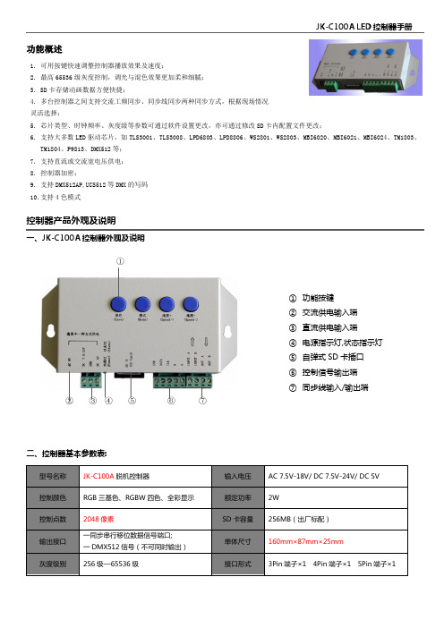
功能概述控制器产品外观及说明一、JK-C100A 控制器外观及说明①② ③ ④ ⑤ ⑥ ⑦二、控制器基本参数表:1. 可用按键快速调整控制器播放效果及速度;2. 最高65536级灰度控制,调光与混色效果更加柔和细腻;3. SD 卡存储动画数据方便快捷;4. 多台控制器之间支持交流工频同步、同步线同步两种同步方式,根据现场情况灵活选择;5. 芯片类型、时钟频率、灰度级等参数可通过软件设置更改,亦可通过修改SD 卡内配置文件更改;6. 支持大多数LED 驱动芯片,如TLS3001、TLS3008、LPD6803、LPD8806、WS2801、WS2803、MBI6020、MBI6021、MBI6024、TM1803、TM1804、P9813、DMX512等;7. 支持直流或交流宽电压供电;8. 控制器加密;9. 支持DMX512AP,UCS512等DMX 的写码 10.支持4色模式① 功能按键 ② 交流供电输入端 ③ 直流供电输入端 ④ 电源指示灯,状态指示灯 ⑤ 自弹式SD 卡插口 ⑥ 控制信号输出端 ⑦ 同步线输入/输出端控制器软件基本操作步骤1、新建工程打开LED Editor软件,选择控制器型号C 100;设置项目的宽高(根据项目实际像素大小);播放帧频;所带灯具芯片类型;控制器输出时钟频率等信息;并设置项目名称及文件保存路径,确定,以下图为例:注意:此信息设置完成后可以在菜单栏“工程设置“下项目属性进行查询或修改。
2、导入动画效果文件菜单栏选择“效果类型”,支持屏幕录制,AVI导入,FLASH导入以及软件自带测试,推移,效果炫彩,如图3、灯具布局文件菜单栏选择“工程设置”菜单,如图选择其中一种方式布局。
4、输出脱机文件菜单栏选择“工程输出”菜单,设置输出GAMMA值和亮度值后,选择“脱机数据输出文件”在项目文件的存储目录下分别生成不同编号的控制机脱机数据文件及配置文件的文件夹(如图),分别将文件夹内的子文件拷贝到已经格式化FAT32的SD卡内;其中”.bin ”文件为为节目效果,软件中编辑几个节目就会生成相应的几个“.bin ” “.ini ”文件为配置文件,配置文件里包含了一些参数信息,可以直接通过“.ini ”修改参数其中”.bin ”文件为为节目效果,软件中编辑几个节目就会生成相应的几个“.bin ” “.ini ”文件为配置文件: 配置文件里包含了一些参数信息, 可以直接通过“.ini ”修改参数, 如图及说明以上说明为简易软件操作说明,具体软件功能及细节请参见软件说明书。

控制器流量控制的说明书控制器流量控制是一种用于管理和调节网络流量的技术。
通过控制器流量控制,可以实现对网络中各个设备之间的传输速率进行合理分配,提高网络的资源利用率,优化网络性能,保障网络的稳定运行。
一、控制器流量控制的作用控制器流量控制在网络管理中起到重要的作用。
它能够防止网络中出现流量过载的情况,避免拥塞问题的发生,保障网络的稳定性。
同时,控制器流量控制还能通过对网络流量进行调度和分配,实现不同设备之间的公平访问,提高网络服务质量。
二、控制器流量控制的原理控制器流量控制主要依靠流控制器对网络中的流量进行监测和控制。
通过对网络中的数据流进行分析和判断,控制器流量控制可以根据预设的策略和算法,对流量进行调度和控制。
其原理主要包括以下几个方面:1. 流量监测:控制器流量控制通过对网络中的流量进行实时监测,获取网络中各个设备的传输情况和带宽利用率。
通过对流量的监测,可以及时发现网络中的异常情况并采取相应的措施。
2. 流量调度:控制器流量控制能够根据事先设定的策略和算法,对网络中的流量进行调度和分配。
通过合理地对流量进行调度,可以避免网络中的拥塞问题,提高网络的性能和稳定性。
3. 流量控制:控制器流量控制可以对网络中的流量进行限制和控制。
通过对网络流量的控制,可以防止某些设备或应用占用过多的带宽资源,影响其他设备或应用的正常访问。
三、控制器流量控制的应用控制器流量控制广泛应用于各种网络环境中,如数据中心、企业内网、云计算等。
它可以根据不同的网络需求和业务场景,灵活地实现流量的管理和控制。
1. 数据中心:在数据中心中,控制器流量控制可以通过对服务器之间的流量进行调度和控制,实现对数据中心网络的优化。
同时,它还可以根据业务需求,对不同应用之间的流量进行分类和管理,提高数据中心的服务质量。
2. 企业内网:在企业内网中,控制器流量控制可以通过对内部员工的上网行为进行监控和控制,防止非法访问和滥用网络资源。
它还可以对网络中的带宽进行合理分配,保证重要业务的流畅进行。
FEATURESPrecision SPDT or DPDT snap-acting micro switch Setpoint adjustable from 15-100% of range Single or dual adjustable set points Fixed or adjustable deadband Wide selection of switch elements TYPICAL USES RefineriesChemical and petrochemical plants Pulp and paper mills Power plants Steel millsWater and sewage treatment plants Pumps, compressors and turbines Dairies and breweries Boilers and burnersReverse osmosis systems and filters Filters and pressesPaint spraying equipment Specialized OEM equipment Pharmaceutical plantsSet Repeatability (Accuracy):±1% of span (Additional setpoint shift of±1% of range per 50 °F from initial setpoint set at 70 °F typical)Switch Type:SPDT or 2 SPDT with independent setpoints,or 2 SPDT acting as DPDT (XC2)Setpoint:Single setpoint, fixed deadbandSingle setpoint, adjustable deadband Independent setpoint, fixed deadbandDeadband:Fixed or adjustable deadband Enclosure Ratings:G Series - NEMA 4X, IP66 L Series - NEMA 4X, IP66Enclosure Material:G Series - 316L Stainless steelL Series - Epoxy coated aluminumProcess Connection:1/4 NPT Female, 1/2 NPT Female,1/4 NPT Female and 1/2 NPT Male CombinationElectrical Termination: ¾ NPT Female Watertight:L Series - UL, CSA, FM, CE, RoHS, CRN, UKCA G Series - UL, CSA, CE, RoHS, CRN, UKCAKEY BENEFITS• environments• • • L-SeriesWatertight EnclosureDifferential Pressure SwitchL-SeriesWatertight Enclosure Pressure SwitchG-SeriesWatertight EnclosureDifferential Pressure SwitchG-SeriesWatertight Enclosure Pressure Switch100# - 100 psi100#®PRESSURE SWITCH – PSI RANGES PRESSURE SWITCH –INCHES OF WATER RANGESDIFFERENTIAL PRESSURE SWITCH –INCHES OF WATER RANGES DIFFERENTIAL PRESSURE SWITCH –PSI DIFFERENTIAL RANGES6.094.12//70A2033 - L-Series D.P. ˝ H2O For reference only, consult Ashcroft for specific dimensional drawingsPRESSURE SWITCH – PSI RANGES PRESSURE SWITCH –INCHES OF WATER RANGESDIFFERENTIAL PRESSURE SWITCH –INCHES OF WATER RANGESDIFFERENTIAL PRESSURE SWITCH –PSI DIFFERENTIAL RANGES70A2113 G Series D.P., psid70A2114 G-SERIES ˝ H2OHIGH PRESSURE PORTLOW PRESSURE PORTFor reference only, consult Ashcroft for specific dimensional drawings。
北京康洁之晨水处理技术有限公北京康洁之晨水处理技术有限公司司BEIJING KANGJIE ZHICHEN WATER TREAT TREATKK ENT CO.,LTD J K B/C 流量型控制器J K B/C 流量型控制器,采用先进的微电脑芯片技术,专门用于水处理设备的流量型再生的控制理设备的流量型再生的控制。
该控制器可用于由多阀或多路阀组成的多罐过滤多罐过滤、、软化软化、、除盐等系统的独立控制除盐等系统的独立控制,,具有瞬时流量具有瞬时流量、、剩余量和累积水量显示累积水量显示、、再生程序预设定再生程序预设定、、系统运行状态显示与其他控制设备连锁控制等特殊功能。
控制器性能特性1.1.ll 设置密码保护2.2.ll J K B 单通道或J K C1-3路多通道流量计脉冲接收3.3.ll 流量计探头K 值选择(根据探头安装管道尺寸按附表查询)4.l 系统流量显示(系统流量显示(0-999t/h 0-999t/h 0-999t/h)及预先设定批量()及预先设定批量()及预先设定批量(1-9999.9t 1-9999.9t 1-9999.9t)的剩)的剩余量递减显示5.5.ll 累计流量查询及清零功能6.6.ll 各路系统(工作、再生、备用、反馈)状态显示7.7.ll 本地强制手动启动再生8.8.l l 再生启动信号输出时间(再生启动信号输出时间(2-99992-9999秒)设定9.9.l l 系统工作模式:系统工作模式:J J K C (C1C1、、D2D2、、D3D3、、E2E2、、E3E3)五种选择)五种选择J K B(C1C1、、C2C2、、C3C3、、C4C4、、C5C5、、D2D2、、D3D3、、D4D4、、D5D5)九种选择)九种选择注:注:C C 型:同时运行轮流再生;型:同时运行轮流再生;D D 型:多用一备;型:多用一备;EE 型:同时运行分别再生1.1.ll 再生系统(出水电磁阀控制)辅助接点输出2.2.ll 停电保护功能:停电后设定的参数保持时间大于3年3.3.ll 仪表外壳采用工程塑料,具有防尘、防腐、防水溅射等功能4.l 仪表采用墙壁挂装或支架悬挂安装形式主要技术指标1.1.l l 流量传感器脉冲量输入:正弦波频率范围0-10K 0-10K,探头(直流,探头(直流,探头(直流))电压幅度4-12V2.2.l l 采样周期:采样周期:0.20.2秒3.3.l l 输出形式:继电器无源接点输出触点容量,触点容量,AC220V/2AAC220V/2A 4.l 馈电输入:无源接点反馈信号5.l 显示方式:背光液晶显示单元,使用寿命显示方式:背光液晶显示单元,使用寿命≥≥10年6.l 仪表电源:开关电源100-265V/AC 功耗5W7.l 使用环境:环境温度4-604-60℃℃相对湿度≤85%RH 8.l 控制器外壳尺寸:控制器外壳尺寸:260X170X105260X170X105260X170X105KKKK为公者益守诚者信克勤者奋好洁者明Contribution Brings Benefits Integrity For TrustDiligence For AchieveKentsSelf-discipline Defines WisdoK为公。
8032流量控制器操作手册8032 型流量控制器目 录1安全说明 (2)1.1使用 (2)1.2安装调试注意事项 (2)1.3符合的标准 (2)2产品说明 (3)2.1结构 (3)2.2测量原理 (3)2.3标准供货 (3)2.4附件 (3)3技术参数 (4)4 安装 (6)4.1 安装建议 (6)4.2 安装 (6)4.3 电气连接 (6)4.3.1连接器 (6)4.3.2晶体管 输出式(NPN/PNP)接线 (7)4.3.3继电器 输出式接线 (7)5 编程 (8)5.1 一般建议 (8)5.2 功能 (8)5.3 编程键 (8)5.4 缺省设置 (8)5.5 正常模式 (9)5.6 可能的开关模式 (9)5.7 校正模式 (10)5.8 模拟模式 (11)6 维护 (12)6.1 清洗 (12)6.2 故障信息 (12)7 附录 (13)7.1 8032易连接举例 (13)7.2 8032控制器标签说明 (14)7.3 流量-流速-通径图 (15)1.1使用8032控制器仅适用于测量液体的流量制造方不负任何责任关于该仪表的保证条款也将无效该仪表只能由专业人员进行安装或维修安装时如有困难1.2 安装调试注意事项则不能防电击始终确认仪表接触介质部分的材质与介质化学兼容。
1.3安装调试注意事项电磁兼容性(EMC): EN 50 081-1(1992), 50 082-2(06-1995)安全性: EN 61 010-1(1993,A2-1995)抗振性: EN 60068-2-6(09-1995)抗震性: EN 60068-2-27(1987)8032 型流量控制器室外安装时应防雨、防紫外线辐射和电磁干扰。
从管道上拆卸该仪表时,应采取所有与工艺有关的必要措施。
2 产品说明 2.1结构8032型流量控制器包括一个带涡轮的S030接头和一个SE32电子模块。
可用于控制电磁阀、激活报警器或建立一个控制回路。
Instruction Manual Flow Controller for AirIN502-44-# / IN502-45-# seriesThe intended use of the flow controller is to monitor and display flow information with the optional connection to IO-Link communication.These safety instructions are intended to prevent hazardous situations and/or equipment damage. These instructions indicate the level of potential hazard with the labels of “Caution,” “Warning” or “Danger.” They are all important notes for safety and must be followed in addition to International Standards (ISO/IEC) *1), and other safety regulations. *1)ISO 4414: Pneumatic fluid power - General rules relating to systems. ISO 4413: Hydraulic fluid power - General rules relating to systems.IEC 60204-1: Safety of machinery - Electrical equipment of machines. (Part 1: General requirements)ISO 10218-1: Manipulating industrial robots -Safety. etc.• Refer to product catalogue, Operation Manual and Handling Precautions for SMC Products for additional information. • Keep this manual in a safe place for future reference.Warning• Always ensure compliance with relevant safety laws and standards.• All work must be carried out in a safe manner by a qualified person in compliance with applicable national regulations.• This product is class A equipment intended for use in an industrial environment. There may be potential difficulties in ensuring electromagnetic compatibility in other environments due to conducted or radiated disturbances.• Refer to the operation manual on the SMC website (URL: https:// ) for more Safety instructions.• Special products (-X) might have specifications different from those shown in the specifications section. Contact SMC for specific drawings.Caution1. When selecting equipment, carefully consider the application, requiredspecifications, and operating conditions (fluid, pressure, flow rate, filtration, and environment), making sure not to exceed the specification range.2. This product is provided for normally typical forms of use in the manufacturing industry. As such, to use the product for applications that may affect the human body directly or indirectly such as caisson shield is not foreseen.3. When the product is used as an air blower for food, install an appropriate filter to eliminate foreign matter in compressed air for air blowing. (Refer to the following example of pneumatic circuit).4. Quality management relating to hygiene for food and medical treatment is not implemented for the product.The product is produced in same line that manufactures other product which uses other materials. In rare cases, some of these materials can be found as a residue. 5. Food grease used• Fluid contact parts: NSF H1 grade grease• Part other than fluid contact parts: NSF H1 grade grease or grease which is not NSF H1 grade6. The grease used in the solenoid valves built into the product is not food grease.Grease may drain out of the product from the solenoid valve EXH. If necessary, pipe it to the outside of the area.7. The product generates particles from the wear of sliding parts inside. When the product is used as an air blower, install an appropriate filter on the outlet of the product to prevent foreign matter from flowing to the downstream. Filters require regular inspection, replacement of the element, and maintenance referring to the operation manual.8. Flush the piping line before using the product for the first time and after it has been replaced. Also, if piping, etc., is to be connected, flush (air blow) before using the product for the first time in order to reduce the effects of the dust generated from the connection, etc. Flushing the line is also required to eliminate contamination resulting from the installation of piping lines. Therefore, be sure to flush the line before running the system.2 Specification2.1 IO-Link specifications (for models with IO-Link)3 Name and function of parts3.1ORIGINAL INSTRUCTIONS3 Name and function of parts (continued)3.2 DisplayPart DescriptionOperation LED LED is ON (orange) when OUT is ON.Main display(red/green)Displays the current controlled flow, setting modestatus, selected display units and error codes.UP buttonSelects the mode and increases the ON/OFF setvalue.SET buttonPress this button to change the mode and toconfirm settings.DOWN buttonChanges the sub display, selects the mode anddecreases the ON/OFF set value.Units display 1(red/green)LED turns ON when STD is selected for thereference condition.Units display 2(red/green)LED indicates the selected flow rate units.Sub display (left) Displays (orange) the display item label.Sub displayDisplays (orange) the display item, setting value,peak/bottom value, etc.IO-Link statusindicator lightDisplays OUT1 output communication status(SIO mode, start-up mode, Pre-operation mode,operation mode) and presence of communicationdata (for products with IO-Link only).•Refer to the operation manual on the SMC website(URL: https://) for more details of the IO-Linkstatus indicator light operation and display.4 Installation4.1 InstallationWarning•Do not install the product unless the safety instructions have been readand understood.•Use the product within the specified operating pressure andtemperature range.4.2 EnvironmentWarning•Do not use in an environment where corrosive gases, chemicals, saltwater, water or steam are present.•Do not use the product in an environment where the product is constantlyexposed to water or oil splashes.•Do not use in an explosive atmosphere.•Do not expose to direct sunlight. Use a suitable protective cover.•Do not install in a location subject to vibration or impact in excess ofthe product’s specifications.•Do not mount in a location exposed to radiant heat that would result intemperatures in excess of the product’s specifications.•Do not use in an area where electrical surges are generated.•Prevent foreign matter such as remnant of wires from entering theproduct4.3 Mounting•Never mount the product in a location where it will be used as afoothold.•Do not mount the product upside down.•Mount the product so that the fluid flows in the direction indicated bythe arrow on the side of the body.•If the EXH port of the solenoid valve may be exposed to water or dust,connect a fitting and tube (sold separately) and route the tube to a safeplace where it will not be affected by water or dust.4 Installation (continued)•Install the product using 4 screws suitable for the product, tightenedaccording to the required tightening torque.•Suitable screw: M5, Tightening torque: 3 N•m ±10%•Screws should be prepared by the user.Refer to the operation manual on the SMC website (URL:https://) for mounting hole details and outlinedimensions.4.4 PipingCaution•Before connecting piping make sure to clean up chips, cutting oil, dustetc.•When installing piping or fittings, ensure sealant material does notenter inside the port.•Tighten the piping to the correct tightening torque: 20 to 25 N•mIf the tightening torque is exceeded, the product can be damaged.If the tightening torque is insufficient, the connection threads andbrackets may become loose.•Confirm that there is no leakage after piping.•When attaching a fitting, the attachment should be held with a wrench.Holding other parts with a wrench may damage the product.5 Wiring5.1 WiringCaution•Connections should only be made with the power supply turned off.•Use a separate route for the product wiring. If wires and cables arerouted together with power or high voltage cables, malfunction mayresult due to noise.•If a commercially available switching power supply is used, be sure toground the frame ground (FG) terminal. If a switch-mode power supplyis connected for use, switching noise will be superimposed and theproduct will not be able to meet the specifications. In that case, inserta noise filter such as a line noise filter/ferrite between the switchingpower supply and the product, or change the switching power supplyto a series power supply.5 Wiring (continued)5.2 Connector installation / removal•Align the lead wire M12 connector with the connector key groove onthe controller, and insert it straight in. Turn the knurled part clockwise.Connection is complete when the knurled part is fully tightened. Checkthat the connection is not loose.•To unplug the connector, loosen the knurled part and pull it straight out.Connector pin layoutWhen used as a Switch output deviceNo. NameWirecolourFunction1 DC(+) Brown 24 VDC2 An IN White Analogue input3 DC(-) Blue 0 V4 OUT Black Switch output5 An OUT Grey Analogue outputWhen used as an IO-Link deviceNo. NameWirecolourFunction1 L(+) Brown 24 VDC2 An IN White Analogue input3 L(-) Blue 0 V4 C/Q BlackIO-Linkcommunication5N.C. /An OUTGreyN.C. or Analogueoutput.6 Outline of SettingsPower is suppliedRefer to the operation manual on the SMC website (URL:https://) for further Setting details.7 Initial Settings•Configure the reference condition, unit of pressure display, and switchoutput PNP/NPN switch.•Reference conditionStandard condition or normal condition can be selected for thestandard reference condition of flow rate.Standard condition: flow rate converted into volume at 20 °C and 101.3kPa (absolute pressure).Normal condition: flow rate converted into volume at 0 °C and 101.3kPa (absolute pressure).•Units selection functionThe flow rate display units selection function allows for selecting L/minor cfm (ft3/min) as the standard unit.The pressure units selection function allows for selecting kPa, MPa,kgf/cm2, bar, or psi as the standard unit.This setting is only available for models with the units selection function.•Switch output typeThe switch output function can be toggled between PNP and NPNoutput.8 Function Selection modeIn measurement mode, press the SET button for at least 1 second but nomore than 3 seconds to display [F 0].The mode in which [F□□] is displayed and changes to the respectivefunction settings are made is referred to as function selection mode.Press the SET button for 2 seconds or longer in function selection modeto return to measurement mode.Note: Some functions are not supported on models with specific productnumbers. [---] will be displayed on the sub display (right) for functions thatare not supported or cannot be selected due to other settings.8.1 Default settings•The factory default settings are as follows.If these settings are acceptable, retain for use.To change a setting, enter function selection mode.•[F 0] Reference condition, unit of pressure display, and switch outputPNP/NPN.Item Default settingReference condition Standard conditionFlow rate display unit L/minPressure display unit kPaSwitch output PNP/NPN switch PNP•[F 1] Setting of OUT1Item Description Default settingOutputmodeLimit deviation tolerance mode, erroroutput mode, or switch output off canbe selected.Limit deviationtolerancemodeReverseoutputSelects which switch output is used,Normal or Reverse.Normal outputLimitdeviationtoleranceSets the switch output on or off whenmeasured flow rate is within the limitdeviation tolerance of set flow rate.±2% F.S.ON delaytimeDelay time (rising) of switch outputcan be selected.0.00 sec.OFF delaytimeDelay time of (falling) switch outputcan be selected.0.00 sec.DisplaycolourSelect the display colour.Output ON:GreenOutput OFF:RedThe product code is displayed for approximately 3 seconds afterpower is supplied. Then, measurement mode is displayed.*: Switch operation starts within approx. 0.2 seconds after power is supplied.[Initial Settings]Set the reference condition, unit of pressure display, and switchoutput PNP/NPN switch.[Function Selection mode]Each function setting can bechanged.[Measurement mode]In this mode, flow rate control and display and switch operationsare performed in accordance with commanded flow rates.This is the basic mode; other modes should be selected for set-point changes and other function settings.[Other Settings]•Zero clear•Key lock• Other Function Settings9 Other Settings• Peak / Bottom value display • Zero clear• Key-lock functionRefer to the operation manual on the SMC website (URL: https:// ) for setting these functions. 10 IO-Link parameter setting• IODD fileIODD (I/O Device Description) is a definition file which provides all properties and parameters required for establishing functions and communication of the device.IODD includes the main IODD file and a set of image files such as vendor logo, device picture and device icon. The IODD file list is shown below.*1: "yyyymmdd" indicates the file preparation date. yyyy is the year, mm is the month and dd is the date.• The latest IODD file can be downloaded from the SMC website (https:// ).11 How to OrderRefer to the SMC website (URL: https:// ) for more How to Order details.12 Outline Dimensions (mm)Refer to the SMC website (URL: https:// ) for details of Outline dimensions.13.1 Error indicationIf the error cannot be reset after the above measures are taken, or errors other than the above are displayed, please contact SMC.14.1 General MaintenanceCaution• Not following proper maintenance procedures could cause the product to malfunction and lead to equipment damage.• If handled improperly, compressed air can be dangerous.• Maintenance of pneumatic systems should be performed only by qualified personnel.• Before performing maintenance, turn off the power supply and be sure to cut off the supply pressure. Confirm that the air is released to atmosphere.• After installation and maintenance, apply operating pressure and power to the equipment and perform appropriate functional and leakage tests to make sure the equipment is installed correctly.• If any electrical connections are disturbed during maintenance, ensure they are reconnected correctly and safety checks are carried out as required to ensure continued compliance with applicable national regulations.• Do not make any modification to the product.• Do not disassemble the product, unless required by installation or maintenance instructions.• How to reset the product after a power cut or when the power has been unexpectedly removedThe settings for the product are retained in memory prior to the power loss or de-energizing of the product.The output condition is also recoverable to that prior to the power loss or de-energizing. However, this may change depending on the operating environment. Therefore, check the safety of the whole installation before operating the product.If the installation is using accurate control, wait until the product has warmed up (approximately 10 to 15 minutes) before operation.15 Limitations of Use15.1 Limited warranty and Disclaimer/Compliance Requirements Refer to Handling Precautions for SMC Products.16 Product disposalThis product should not be disposed of as municipal waste. Check your local regulations and guidelines to dispose of this product correctly, in order to reduce the impact on human health and the environment.17 ContactsRefer to or www.smc.eu for your local distributor / importer.URL: https:// (Global) https://www.smc.eu (Europe) SMC Corporation, 4-14-1, Sotokanda, Chiyoda-ku, Tokyo 101-0021, Japan Specifications are subject to change without prior notice from the manufacturer. © 2022-2023 SMC Corporation All Rights Reserved. Template DKP50047-F-085M。