Material properties
- 格式:doc
- 大小:61.00 KB
- 文档页数:4

低温材料物性表Presented at the 11th International Cryocooler ConferenceJune 20-22, 2000Keystone, Co Cryogenic Material Properties Database Cryogenic Material Properties DatabaseE.D. Marquardt, J.P. Le, and Ray RadebaughNational Institute of Standards and TechnologyBoulder, CO 80303ABSTRACTNIST has published at least two references compiling cryogenic material properties. These include the Handbook on Materials for Superconducting Machinery and the LNG Materials & Fluids. Neither has been updated since 1977 and are currently out of print. While there is a great deal of published data on cryogenic material properties, it is often difficult to find and not in a form that is convenient to use. We have begun a new program to collect, compile, and correlate property information for materials used in cryogenics. The initial phase of this program has focused on picking simple models to use for thermal conductivity, thermal expansion, and specific heat. We have broken down the temperature scale into four ranges: a) less than 4 K, b) 4 K to77 K, c) 77 K to 300 K, and d) 300 K to the melting point. Initial materials that we have compiled include oxygen free copper, 6061-T6 aluminum, G-10 fiberglass epoxy, 718 Inconel, Kevlar, niobium titanium (NbTi), beryllium copper, polyamide (nylon), polyimide, 304 stainless steel, Teflon, and Ti-6Al-4V titanium alloy. Correlations are given for each material and property over some of the temperature range. We will continue to add new materials and increase the temperature range. We hope to offer these material properties as subroutines that can be called from your own code or from within commercial software packages. We will also identify where new measurements need to be made to give complete property prediction from 50 mK to the melting point.INTRODUCTIONThe explosive growth of cryogenics in the early 50’s led to much interest in material properties at low temperatures. Important fundamental theory and measurements of low temperature material properties were performed in the 50’s, 60’s, and 70’s. The results of this large amount of work has become fragmented and dispersed in many different publications, most of which are out of print and difficult to find. Old time engineers often have a file filled with old graphs; young engineers often don’t know how to find this information. Since most of the work was performed before the desktop computer became available, when data can be found, it is published in simple tables or graphically, making the information difficult to accurately determine and use.NIST has begun a program to gather cryogenic material property data and make it available in a form that is useful to engineers. Initially we tried to use models based upon fundamental physics but it soon became apparent that the models could not accurately predict properties overTable 1A . Coefficients for thermal conductivity for metals.Coeff.6061 -T6 Aluminum 304 SS 718 Inconel Beryllium copper Ti-6Al-4V a0.07918 -1.4087 -8.28921 -0.50015 -5107.8774 b1.09570 1.3982 39.4470 1.93190 19240.422 c-0.07277 0.2543 -83.4353 -1.69540 -30789.064 d0.08084 -0.6260 98.1690 0.71218 27134.756 e0.02803 0.2334 -67.2088 1.27880 -14226.379 f-0.09464 0.4256 26.7082 -1.61450 4438.2154 g0.04179 -0.4658 -5.72050 0.68722 -763.07767 h-0.00571 0.1650 0.51115 -0.10501 55.796592 I0 -0.0199 0 0 0 data range 4-300 K 4-300 K 4-300 K 4-300 K 20-300 Ka large temperature range and over different materials. Our current approach is to choose a few simple types of equations such as polynomial or logarithmic polynomials and determine the coefficients of different materials and properties. This will allow engineers to use the equations to predict material properties in a variety of ways including commercial software packages or their own code. Integrated and average values can easily be determined from the equations. These equations are not meant to provide any physical insight into the property or to provide ‘standard’ values but are for working engineers that require accurate values.MATERIALSInitial materials that we have compiled include oxygen free copper, 6061-T6 aluminum, G-10CR fiberglass epoxy, 718 Inconel, Kevlar 49, niobium titanium (NbTi), beryllium copper, polyamide (nylon), polyimide, 304 stainless steel, Teflon, and Ti-6Al-4V titanium alloy. These were chosen as some of the most common materials used in cryogenic systems in a variety of fields.MATERIAL PROPERTIESThermal ConductivityWidely divergent values of thermal conductivity for the same material are often reported in the literature. For comparatively pure materials (like copper), the differences are due mainly to slight material differences that have large effects on transport properties, such as thermal conductivity, at cryogenic temperatures. At 10 K, the thermal conductivity of commercial oxygen free copper for two samples can be different by more then a factor of 20 while the same samples at room temperature would be within 4%. It is also not uncommon for some experimental results to have uncertainties as high as 50%. Part of our program is to critically evaluate the literature to determine the best property values. Data references used to generate predictive equations will be reported.The general form of the equation for thermal conductivity, k , islog()log (log )(log )(log )(log )(log )(log )(log ),k a b T c T d T e T f T g T h T i T =++++++++2345678 (1)where a , b , c , d, e , f , g , h , and i are the fitted coefficients, and T is the temperature. These are common logarithms. While this may seem like an excessive number of terms to use, it was determined that in order to fit the data over the large temperature range, we required a large number of terms. It should also be noted that all the digits provided for the coefficients should be used, any truncation can lead to significant errors. Tables 1A and 1B show the coefficients for a variety of metals and non-metals. Equation 2 is the thermal conductivity for an average sample of oxygen free copper. It should be noted that thermal conductivity for oxygen free copper canTable 1B . Coefficients for thermal conductivity for non-metals.Coeff. Teflon Polyamide (nylon) Polyimide (Kapton) G10 CR (norm) G10 CR(warp)a2.7380 -2.6135 5.73101 -4.1236 -2.64827 b-30.677 2.3239 -39.5199 13.788 8.80228 c89.430 -4.7586 79.9313 -26.068 -24.8998 d-136.99 7.1602 -83.8572 26.272 41.1625 e124.69 -4.9155 50.9157 -14.663 -39.8754 f-69.556 1.6324 -17.9835 4.4954 23.1778 g23.320 -0.2507 3.42413 -0.6905 -7.95635 h-4.3135 0.0131 -0.27133 0.0397 1.48806 I0.33829 0 0 0 -0.11701 data range 4-300 K4-300 K 4-300 K 10-300 K 12-300 K Figure 1. Thermal conductivity of various materials.vary widely depending upon the residual resistivity ratio, RRR, and this equation should be used with caution. The thermal conductivities are displayed graphically in Figure 1.log .............k T T T T T T T T =?+?+?+?+22154088068029505004831000032071047461013871002043000012810515205152(2) Specific HeatThe specific heat is the amount of heat energy per unit mass required to cause a unit increase in the temperature of a material, the ratio of the change in energy to the change in temperature. Specific heats are strong functions of temperature, especially below 200 K. Models for specific heat began in the 1871 with Boltzmann and were further refined by Einstein and Debye in the early part of the 20th century. While there are many variations of these first models, they generally only provide accurate results for materials with perfect crystal lattice structures. TheTable 2. Coefficients for specific heat. Coeff. OFCHcopper 6061 -T6 Aluminum 304 SS G-10 Teflon a-1.91844 46.6467 22.0061 -2.4083 31.8825 b-0.15973 -314.292 -127.5528 7.6006 -166.519 c8.61013 866.662 303.6470 -8.2982 352.019 d-18.99640 -1298.30 -381.0098 7.3301 259.981 e21.96610 1162.27 274.0328 -4.2386 -104.614 f-12.73280 -637.795 -112.9212 1.4294 24.9927 g3.54322 210.351 24.7593 -0.24396 -3.20792 h-0.37970 -38.3094 -2.239153 0.015236 0.165032 I0 2.96344 0 0 0 data range 3-300 K 3-300 K 3-300 K 3-300 K 3-300 KFigure 2. Specific heat of various materials.specific heat of many of the engineering materials of interest here is not described well by these simple models. The general form of the equation is the same as Equation 1. Table 2 shows the coefficients for the specific heat. Figure 2 graphically shows the specific heats.Thermal ExpansionFrom an atomic perspective, thermal expansion is caused by an increase in the average distance between the atoms. This results from the asymmetric curvature of the potential energy versus interatomic distance. The anisotropy results from the differences in the coulomb attraction and the interatomic repulsive forces.Different metals and alloys with different heat treatments, grain sizes, or rolling directions introduce only small differences in thermal expansion. Thus, a generalization can be made that literature values for thermal expansion are probably good for a like material to within 5%. This is because the thermal expansion depends explicitly on the nature of the atomic bond, and only those changes that alter a large number of the bonds can affect its value. In general, largeTable 3A . Integrated Linear Thermal Expansion Coefficients for Metals.Coeff.6061 -T6 Aluminum 304 SS 718 Inconel Beryllium copper Ti-6Al-4V NbTi a-4.1272E+02 -2.9546E+02-2.366E+02-3.132E+02-1.711E+02 -1.862E+02b-3.0640E-01 -4.0518E-01-2.218E-01-4.647E-01-2.171E-01 -2.568E-01 c8.7960E-03 9.4014E-03 5.601E-03 1.083E-02 4.841E-03 8.334E-03 d-1.0055E-05 -2.1098E-05-7.164E-06-2.893E-05-7.202E-06 -2.951E-05 e0 1.8780E-080 3.351E-080 3.908E-08 data range 4-300 K 4-300 K 4-300 K 4-300 K 4-300 K 4-300 KTable 3B. Integrated Linear Thermal Expansion Coefficients for Non-metals.Coeff. Teflon Polyamide G10 CR (norm) G10 CR(warp)a-2.165E+03 -1.389E+03-7.180E+02-2.469E+02 b3.278E+00 -1.561E-01 3.741E-01 2.064E-01 c-8.218E-03 2.988E-02 8.183E-03 3.072E-03 d7.244E-05 -7.948E-05-3.948E-06-3.226E-06 e0 1.181E-07 0 0 data range 4-300 K 4-300 K 4-300 K 4-300 Kchanges in composition (10 to 20%) are necessary to produce significant changes in the thermal expansion (~5%), and different heat treatments or conditions do not produce significant changes unless phase changes are involved.8Most of the literature reports the integrated linear thermal expansion as a percent change in length from some original length generally measured at 293 K,()/.L L L T ?293293 (3) Where L T is the length at some temperature T and L 293 is the length at 293 K. While this is a practical way of measuring thermal expansion, the more fundamental property is the coefficient of linear thermal expansion,α,α()().T L dL T dT=1 (4) The coefficient of linear thermal expansion is much less reported in the literature. In principal, we can simply take the derivative of the integrated linear thermal expansion that results in the coefficient of linear thermal expansion. While we have had success with this method over limited temperature ranges, we have not yet determined an equation form for the integrated expansion value that results in a good approximation of coefficient of linear thermal expansion. For the time being, we will report the integrated linear thermal expansion as a change in length and provide the coefficient of linear thermal expansion when it is directly reported in the literature. The general form of the equation for integrated linear thermal expansion is L L L a bT cT dT eT T ?=++++??293293234510(). (5) Tables 3A and 3B provide the coefficients for the various materials while Figure 3 plots the integrated linear thermal expansions.FUTURE PLANSWe plan to continually add new materials, properties, and to expand the useful temperature range of the predictive equations for engineering use. We will report results in the literature but will also update our website on a continual basis. The initial phase of the program was a learningFigure 3. Integrated linear thermal expansion of various materials.experience on how to handle the information in the literature as well as for the development of a standard set of basic equation types used to fit experimental data. By using just a few types of equations, we hope to make the information easier to use. We shall now focus on developing large numbers of equations for a variety of materials and properties. Please check our web site at /doc/e6c9c70608a1284ac85043da.html /div838/cryogenics.html for updated information.REFERENCES1. Berman, R., Foster, E.L., and Rosenberg, H.M., "The Thermal Conductivity of SomeTechnical Materials at Low Temperature." Britain Journal of Applied Physics, 1955. 6: p.181-182.2. Child, G., Ericks, L.J., and Powell, R.L., Thermal Conductivity of Solids at RoomTemperatures and Below. 1973, National Bureau of Standards: Boulder, CO.3. Corruccini, R.J. and Gniewek, J.J., Thermal Expansion of Technical Solids at LowTemperatures. 1961, National Bureau of Standards: Boulder, CO.4. Cryogenic Division, Handbook on Materials for Superconducting Machinery. Mechanical,thermal, electrical and magnetic properties of structure materials. 1974, National Bureau of Standards: Boulder, CO.5. Cryogenic Division, LNG Materials and Fluids. 1977, National Bureau of Standards:Boulder, CO.6. Johnson, V.J., WADD Technical Report. Part II: Properties of Solids. A Compendium ofThe Properties of Materials at Low Temperature (phase I). 1960, National Bureau of Standard: Boulder, CO.7. Powells, R.W., Schawartz, D., and Johnston, H.L., The Thermal Conductivity of Metals andAlloys at Low Temperature. 1951, Ohio State University.8. Reed, R.P. and Clark, A.F., Materials at Low Temperature. 1983, Boulder, CO: AmericanSociety for Metals.9. Rule, D.L., Smith, D.R., and Sparks, L.L., Thermal Conductivity of a Polyimide FilmBetween 4.2 and 300K, With and Without Alumina Particles as Filler. 1990, National Institute of Standards and Technology: Boulder, CO.10. Simon, N.J., Drexter, E.S., and Reed, R.P., Properties of Copper Alloys at CryogenicTemperature. 1992, National Institute of Standards and Technology: Boulder, CO.11. Touloukian, Y.S., Recommended Values of The Thermophysical Properties of Eight Alloys,Major Constituents and Their Oxides. 1965, Purdue University.12. Veres, H.M., Thermal Properties Database for Materials at Cryogenic Temperatures. Vol. 1.13. Ziegler, W.T., Mullins, J.C., and Hwa, S.C.O., "Specific Heat and Thermal Conductivity ofFour Commercial Titanium Alloys from 20-300K," Advances in Cryogenic Engineering Vol. 8, pp. 268-277.。
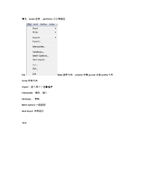
情况;zones 区域;partitions划分存储区File Read 读取文件:scheme 方案 journal 日志 profile 外形Write 保存文件Import:进入另一个运算程序Interpolate:窜改,插入Hardcopy :复制,Batch options 一组选项Save layout 保存设计GridCheck 检查Info 报告:size 尺寸;memory usage内存使用Polyhedral多面体:Convert domain变换范围Convert skewed cells 变换倾斜的单元Merge 合并Separate 分割Fuse (Merge的意思是将具有相同条件的边界合并成一个;Fuse将两个网格完全贴合的边界融合成内部(interior)来处理,比如叶轮机中,计算多个叶片时,只需生成一个叶片通道网格,其他通过复制后,将重合的周期边界Fuse掉就行了。
注意两个命令均为不可逆操作,在进行操作时注意保存case) Zone 区域: append case file 添加case文档Replace 取代;delete 删除;deactivate使复位;Surface mesh 表面网孔Reordr 追加,添加:Domain 范围;zones区域;Print bandwidth 打印Scale 单位变换Translate 转化Rotate 旋转 smooth/swap 光滑/交换Define Models 模型: solver 解算器Pressure based 基于压力 density based 基于密度implicit 隐式, explicit 显示Space 空间:2D,axisymmetric(转动轴),axisymmetric swirl (漩涡转动轴);Time时间:steady 定常,unsteady 非定常Velocity formulation 制定速度:absolute绝对的; relative 相对的Gradient option 梯度选择:以单元作基础;以节点作基础;以单元作梯度的最小正方形。

关于科技的英文演讲稿篇一:科技与未来英语演讲The development of science and technology makes our life more comfortable and , scientists have created many problems, which are not easy to be resolved,such as air pollution, the deterioration of environment and the scarcity of natural resources, to which we must some solutions. Modern science and technology render people many advantages. Modern telecommunication shortens the distance between people and makes communication much easier. Internet is widely used now not only for collection of abundant information but also for correspondence. Email, the most effective communication device now, is becoming very popular. Besides, telephone and mobile phone make contact more convenient than before. Modern transportation, such as airplanes and high-speed trains make our journey smooth and fast. With the help of modern transportation, people can go everywhere they prefer to. The journey to outer space and other planets is not a dream any more. Rocketsand space shuttles can help us realize the dream of space travel. Modern medicine prolongs peopleslife and relieves patients of sufferings from many diseases. Cancer and AIDS are fatal to peoples health. Thanks to the endeavors scientists have made, these diseases become treatable. However, the process of scientific development also arouses many sever problems to our human beings. Internet, though widely used in modern communication, is easy to be destroyed by computer virus. Outer space exploration has produced much waste in the space. A tiny metal, a screw, for example can destroy a flying man-made is making natural resources become scarce. Confronted with these problems, scientists are seeking prompt and feasible solutions. The development of science and technology bring about both positive and negative effects to us. We must eliminate the positive effects to the least extent.篇二:英语演讲稿科技关于科技的英语演讲稿—technology and future the presence of students, ladies and teachers, everyone!i was prepared intervalsof cloud today, in honor here entitled technology and future speech, i am very proudof both, but some unease. in recent years, we have seen our great motherland, thecause of the rapid development of technology, which allow me to a chinese i feel veryproud. remember that long ago, cell phone use almost the only one, which is called,but a few years ago, cell phones has undergone great changes, not only look morebeautiful, but also use more, you can use the phones to take pictures, meetings,internet, textmessages, etc. a series of things that i their life more convenient, so i am moreaware of the strength of the technology, but i am just a fledglings students,technology as the word also aware of the limited, i am unable to use some very difficulttheory to elaborate technology xuanji, no right to work on their elders i can promiseof the technology blueprint. but i am willing to use a student’s perspective to theimagine technology and the future. from geneticengineering is a live princes dream, nano-technology - not washing your clothing, promises; from artificial intelligencewill give you a cute robot dog warm, transgenicopening up to the current level of science and technology has lead a large country,our motherland experienced a number of ups and downs, how many difficulties and bumpyhowever, we still back all of the motherland, the motherland because we firmly believethat - not only technological change destiny, can change the , but we will not give up that easily, we use our youth to predecessorsvowed: never live up to their predecessors of our hope. looking back at the historyof civilization, anderson is the history of mankind against the darkness of ignorance,is the参考翻译:在场的学生们,女士们,老师,大家好!我准备间隔云今天,为了纪念在这里题为“科技与未来”的讲话,我感到非常自豪的两个,但有些不安。
Material properties of basalt fibre reinforced concrete made with recycled earthquakewasteJ.F.Dong a ,b ,Q.Y.Wang b ,⇑,Z.W.Guan c ,daSchool of Architecture and Environment,Sichuan University,Chengdu 610065,ChinabKey Laboratory of Energy Engineering Safety and Disaster Mechanics,Ministry of Education,Sichuan University,Chengdu 610065,China cSchool of Mechanical Engineering,Chengdu University,Chengdu 610106,China dSchool of Engineering,University of Liverpool,Liverpool L693GQ,UKh i g h l i g h t sMechanical properties and microstructures of basalt fibre reinforced RAC were studied. Effects of the RCA replacement ratio on compressive behaviour of the RAC and BFRC columns. The influence of the basalt fibre content on the mechanical properties and cyclic axial compression. The basalt fibre could be used in RAC to enhance its structural behaviour.a r t i c l e i n f o Article history:Received 21November 2015Received in revised form 1August 2016Accepted 28August 2016Available online 7November 2016Keywords:Recycled aggregate concrete Fibre reinforced concrete Basalt fibre SEM imageMechanical propertya b s t r a c tConcrete waste constitutes the major proportion of construction waste which counts on about 50%of the total wastes generated.The use of recycled aggregates serves to promote the recycling of concrete in the construction industry as well as to suit the reconstruction need in earthquake areas.This paper presents an investigation on mechanical properties and microstructures of basalt fibre (BF)reinforced recycled aggregate concrete (RAC).The main parameters considered in the study are the replacement ratio of recy-cled coarse aggregates (RCA)and the content of the basalt fibre.The research work is focused on the influ-ences of the above parameters on the failure mode,compressive strength,tensile strength,elastic modulus,Poisson’s ratio and the ultimate strain of the BF reinforced RAC.The results show that the mechanical properties of RAC can be enhanced by using BF.The SEM observations of the concrete reveal that the BF accumulated in pores and on the surface of the attached mortar can not only strengthen the RAC,but also improve the microstructure of the interfacial transition zone (ITZ),which further enhances the strength and ductility of the RAC.Therefore,the basalt fibre reinforced RAC can be used in construc-tion to reduce the environmental hazards from a large amount of earthquake waste from collapsed buildings.Ó2016Elsevier Ltd.All rights reserved.1.IntroductionIn recent years,due to the increasing demand for infrastructure development,the consumption of concrete keeps growing.It is estimated that the emission of carbon dioxide from the concrete production is about 1.35billion tons annually or about 7%of the total greenhouse gas emissions to the earth’s atmosphere [1].The earthquake on 12May 2008in Sichuan was one of the most destructive earthquakes in modern Chinese history,which gener-ated approximately 382million tons of construction wastes just from the collapsed buildings alone [2].Recycling construction wastage is a promising way towards sustainable construction as it is beneficial to the environmental preservation and saving of nat-ural resources.Therefore,utilizing the recycled coarse aggregates (RCA)obtained from crushing of demolition concrete or earth-quake waste concrete for a new concrete production is one of the significant efforts in achieving a sustainable construction.There has been some work already carried out to explore the important properties of the recycled aggregate concrete (RAC),such as work-ability,compressive,flexural and tensile strengths,elastic modulus and sources of the concrete waste [3–5].It is shown that the failure mode of RAC is similar to that of the natural aggregate concrete/10.1016/j.conbuildmat.2016.08.1180950-0618/Ó2016Elsevier Ltd.All rights reserved.⇑Corresponding author.E-mail addresses:dongjf@ (J.F.Dong),wangqy@ (Q.Y.Wang),zhongwei.guan@ (Z.W.Guan).Construction and Building Materials 130(2017)241–251Contents lists available at ScienceDirectConstruction and Building Materialsjournal homepage:w w w.e l s e v i e r.c o m /l oc a t e /c o n b u i l d m at(NAC)[6,7];however,there are some properties of RAC that are inferior to those of concrete made with natural aggregates[8–11].The mechanical properties of RAC are influenced greatly by RCA, which gives a higher porosity and water absorption,lower density and strength,and weaker interfacial transition zones(ITZs)than those of natural aggregate concrete.Casuccio et al.[12]and Liu et al.[13]found that the failure of RAC is characterised as a lower strength and elastic modulus,a higher peak strain and a significant reduction in fracture energy.Kwan et al.[14]indicated that the RCA content has an inverse effect on the compressive strength, tensile strength and elastic modulus,as RCA increase the porosity and the presence of weak interfacial bonding between aggregate and matrix.The negative effects of RCA on RAC properties limit the structural uses of this material in civil engineering.However, some researchers pointed out that the shortcomings of RCA could be mitigated by appropriate mixing approaches[15–17],such as surface treatment or pre-soaking recycled aggregates[18–20]. Based on the microstructures through scanning electron micro-scopy(SEM),Katz[21]found that RCA are covered with loose particles which prevent the good bonding between the cement matrix and RCA.The author also found that the treatments by impregnation of silica fume solution and by ultrasonic cleaning could increase the compressive strength by15%and7%,respec-tively[21].These treatments canfill up some pores and cracks in RCA,resulting in a denser concrete,and further improve the inter-facial zone and give a higher strength when compared to the RAC without those treatments.Nevertheless,there still exists a weak ITZ,as water can be easily absorbed by small pores and thus form Ca(OH)2crystals.A possible approach forward is to utilizefibres as reinforcements for concrete to improve its ITZ,strength and ductility by preventing and reducing the occurrence of macro or micro cracks.It has been shown that the presence offibres could increase the concrete strength due to the sewing effect on the crack initi-ation and propagation,and also offer the concrete with enhanced ductility.There are various types offibres that can be added to concrete mixing,including steelfibre[22,23],glassfibre[24,25] and polyethylene terephthalate(PET)fibre[26,27].However, thosefibres appear to reduce the workability of concrete.Basalt fibre(BF),made from volcanic rock through melting process with environmental friendly and non-hazardous nature[28–30], possesses excellent physical and mechanical properties,such as high chemical stability[31],non-combustible and non-explosive nature[32],resistance to high temperature[29],better mechani-cal properties as well as cheaper than E-glassfibres[33].As the result,BF has been used as a reinforcing material for concrete recently.In regarding to the BF reinforced concrete under impact loading,the researches carried out by Li and Xu[34,35]showed that the addition of basaltfibres could improve deformation and energy absorption capacities of the concrete significantly,whereas there is no notable enhancement on the dynamic compressive strength.There has been extensive experimental research on either the physical properties of RAC andfibre reinforced concrete,as indi-cated above.Also,some attempts were made to study the mechanical properties offibre reinforced RAC with the effects offibre content and replacement ratios offine and coarse aggre-gates[25,28,36].However,regarding to the influence of the basaltfibre content on the physical and mechanical properties of recycled aggregate concrete,there is limited research output that has been published in this aspect.Therefore,mechanical properties of RCA,RAC and BF reinforced RAC(BFRC)were inves-tigated in this study.In addition,SEM microstructures of such materials were obtained to have insight into understanding of the microstructures of the concrete materials in reflection to their mechanical properties.2.Experimental details2.1.MaterialsOrdinary Portland Cement(namely32.5grade),complying with the Chinese Standard GB175-1999[37]was used in the study.The chemical compositions,together with the physical and mechanical properties,are shown in Tables1and2,respectively.For the nat-ural coarse andfine aggregates,crushed aggregates and river sand with a maximum size of2.36mm were prepared,respectively.The recycled coarse aggregates used in this study were obtained by crushing the earthquake waste concrete from the collapsed buildings in Dujiangyan after the Sichuan earthquake on12May, 2008.The physical properties of the natural coarse aggregates (NCA)and the recycled coarse aggregates are shown in Table3. The nominal size of NCA and RCA is20mm and their grading curves are shown in Figs.1and2,respectively.It can be seen that the size grading of the coarse aggregates is similar,which comply with the requirements of Chinese Standard GB/T14685-2001[38].The chopped basaltfibres were provided by Chengdu Dianshi Basalt Fibre Technology Engineering Co.Ltd.(China).Thefibres are in bundles so that they do not have uniform diameter,as shown in Fig.3.The length of the individualfibre is between15 and19mm,with13l m in diameter.The other properties supplied by the manufactory,together with the specific weight,tensile strength,elasticity modulus and elongation at failure,are shown in Table4.2.2.Concrete mixturesExperiments were conducted on the use of basaltfibres and recycled coarse aggregates in concrete composites.When making recycled aggregate concrete,cement,river sand,water and three RCA replacement ratios,i.e.0,50and100%,were used.In addition, three portions of basaltfibre(0,2and4kg/m3)were applied in the recycled aggregate concrete to make the corresponding BF rein-forced RAC.Mix design was in accordance with the Chinese Stan-dard JGJ55-2011[39],and concrete specimens were prepared using different proportions of RCA,NCA and BF,as listed in Table5. In terms of B0R0,the letter B represents the basaltfibre,thefirst number‘0’represents the content of basaltfibres,the letter R rep-resents the RAC,and the number followed represents the percent-age of RCA.Before mixing,the RCA were pre-soaked to minimize their effects on the workability and water/cement ratio of the con-crete,due to their high water absorption[5].The amount of water used to pre-soak the RCA was calculated according to the effective absorption of RCA to maintain a constant water/cement ratio of 0.53.The different dosages(in kg/m3)of the normal and recycled aggregate concrete between the NCA and the RCA,as shown in Table5,were due to their different specific gravity values(Table3). The sand,cement,coarse aggregates and basaltfibres were placed and dry-mixed for about2min before water was added,then slump tests were carried out to determine the corresponding workability.2.3.Specimen preparation and test methodThe tests conducted in this study include the evolution of com-pressive strength with different proportions of recycled coarse aggregates at the ages of3,7,14,21,28and90days,along with the splitting tensile strength,the four-pointflexural strength,the elastic modulus and the Poisson’s ratio of the recycled aggregate concrete with or without basaltfibres added at the age of28days. Here,a universal testing machine with a3000kN capacity was used,with a loading rate set to0.5kN/s.All the specimens242J.F.Dong et al./Construction and Building Materials130(2017)241–251prepared were covered by a hemp bag to maintain a relative humidity of over90%at room temperature when they were removed from moulds.Both the compressive strength and splitting tensile strength were measured on cubes of150mm, the four-pointflexural strength is measured on prisms of 100Â100Â400mm,and the elastic modulus and Poisson’s ratio are measured on prisms of150Â150Â300mm.In each experi-ment,triplicate samples were tested to confirm their repeatability of test results and the mean value was calculated.In the experiment of mechanical properties of concrete col-umns,the circular solid RAC columns with external diameter of 100mm and height of400mm were tested in concentric compres-sion until failure using a universal machine mentioned above.In order to investigate the influence of BF on the mechanical proper-ties of RAC columns,the portions of2and4kg/m3BF were added to fabricate the BFRC columns.During compression testing,a monotonous force was applied at a constant loading rate of 0.5kN/s to the RAC/BFRC columns.Both linear electric resistance strain gauges and linear variable displacement transducers(LVDTs) were used to record local axial and hoop deformations and overall displacements.The load was applied incrementally and suspended temporarily at each loading level to record the strain readings and the corresponding displacements.For the BFRC columns with the BF content of4kg/m3,the cyclic load during the test was taken according to the following intervals: at every20kN load increment from the minimum load(P min)of 30kN up to the maximum load(P max)of110kN.At every loading cycle,i.e.the load from P min to P max,then to P min,the load interval was set to the20%of the P max to record the data.If the specimens were not failed after the cyclic tests,the columns were loadedTable1Oxide and chemical composition of cement.SiO2(%)Al2O3(%)Fe2O3(%)MgO(%)CaO(%)SO3(%)K2O(%)Loss on ignition(%)20.27 4.25 3.01 1.0763.12 2.060.48 1.05Table2Physical and mechanical properties of ordinary Portland cement.Consistency(%)Setting time(min)Flexural strength(MPa)Compressive strength(MPa) Initial Final3d28d3d28d 47135240 4.6 6.612.539.5Table3Physical properties of natural and recycled coarse aggregates.Coarse aggregate Grading(mm)Bulk density(kg/m3)Apparent density(kg/m3)Water absorption(%)Crushing index(%) NCA 2.36–19.00138223470.2511.58RCA 2.36–19.0012192172 2.2513.42Fig.1.The natural and recycled coarse aggregates.Fig.3.Basaltfibres for concrete production.J.F.Dong et al./Construction and Building Materials130(2017)241–251243monotonically to failure at a load increment of10kN.The detail of cyclic loading applied is shown in Fig.4.2.4.SEM samplesAll the SEM specimens of the recycled aggregate concrete with or without basaltfibre were prepared from the sections recovered from the failed specimens with a28-day age,which were then investigated using Hitachi S-4800in Sichuan University of China. The specimens were pre-soaked in the absolute alcohol for one day and dried in vacuum at60°C for15min.For the specimens to be used to observe ITZs,typical interfaces were chosen from the broken sections before the specimens were coated with Au for analysis.3.Results and discussion3.1.DensityThe mean densities of the recycled aggregate concrete with dif-ferent basaltfibre content are shown in Table5and Fig.5.The den-sity of the RAC(Type1in Table5)decreases with increasing in RCA content from0%to100%.This is likely related to the low density of the recycled coarse aggregates,as shown in Table3.The densities of Type2and Type3concrete with added2and4kg/m3of basalt fibre are higher than the density corresponding to Type1RAC.The results may be due to adding basaltfibres,which absorb some water for hydration and reduce the water content during the con-crete mix.As the results,more compaction was applied which increases the densification of cement composites,further leading to a higher density.This is also applied to the glassfibre reinforced concrete[25].Therefore,the more basaltfibre content,the higher of density,since the addition of basaltfibre in the mix composi-tions contributes to an increase in the density primarily due to the excessive compaction during the concrete casting and also the high density of basaltfibre of2600kg/m3(Table4).pressive strengthsTable6shows the compressive cube strengths(f cu)correspond-ing to the curing periods of3,7,14,21,28and90days,together with the28-day compressive prism strength(f c),theflexural strength(f f)and the ratio of the prism strength to the cubic strength at28days(a c),for three types of the concrete.At the evaluated age from3to90days,the compressive strengths of Type1RAC are similar to those of the BF reinforced RAC(Types2and3).The similar compressive strengths obtained in recycled aggregate concrete with an increase in the RCA replace-ment ratio may be attributed to the lower effective water/cement ratio of the normal concrete with respect to RAC.This is because the same water content is used in all concretes(Table5).However, the RCA was pre-soaked before preparing for concrete,which gaveTable4Mechanical characteristics of basaltfibre(BF).Fibre type Equivalent diameter(l m)Specific weight(kg/m3)Tensile strength(N/mm2)Elastic modulus(N/mm2)Ultimate elongation(%) BF132600200093,0003Table5Mix proportions of concrete(1m3).Type Specimen I.D.Fibre content(kg/m3)RCA ratio(%)W/C(%)Unit weight(kg/m3)Density(kg/m3)Slump(mm)Water Cement Sand NCA RCA1B0R0000.53180.5340.6653.61215.702390.439.7 B0R500500.53180.5340.6648.4609.6609.62384.441.4B0R10001000.53180.5340.6632.801186.42344.245.32B2R0200.53180.5340.6653.61215.702398.534.6 B2R502500.53180.5340.6648.4609.6609.62408.235.4B2R10021000.53180.5340.6632.801186.42358.233.73B4R0400.53180.5340.6653.61215.702410.631.9 B4R504500.53180.5340.6648.4609.6609.62417.532.7B4R10041000.53180.5340.6632.801186.42357.330.1244J.F.Dong et al./Construction and Building Materials130(2017)241–251the much higher water absorption in RAC.Fig.6shows that the RCA and BF contents have a significant influence on compressive strength of the concrete.At the age of 90days,all concrete samples demonstrate compressive strength at least 20%higher than those obtained at 28days,showing that a longer curing period gives a higher strength of RCA.This is likely due to the recycled aggregate concrete taking longer time to reach the full hydration state and gain the full compressive strength than the normal aggregate con-crete [1,40].Regarding to the prism compressive strength at a curing time of 28days,there is an enhancement for all mixes in relation to an optimum content of fibre in each percentage of RCA.The Type 2concrete with 2kg/m 3BF content and 100%RCA replacement ratio shows a notably higher prism strength (33%)compared with that of the same type with 0%RCA,as shown in Fig.7.Such the strength is also more than 20%higher than those of the Type 1(zero BF con-tent)and Type 3(4kg/m 3BF content)at the same replacement ratio of RCA.This is likely attributed to the higher compressive strength of B2R100,as indicated in Fig.6and Table 6.The higher BF content does not necessarily lead to a higher prism strength,which may be caused by non-uniform mixing of BF.For concrete without RCA,the strength increases with increasing the BF content up to 4kg/m 3(0.16%).However,there is a small reduction (5%)on compressive strength when 50%RCA and 0.16%BF were used.The results may be related to the BF absorbed CaO from Ca(OH)2pro-duced by the hydration of Portland cement,which means that less CaO available for metakaolin to produce materials that have cementitious properties [28].3.3.Elastic modulus and Poisson’s ratioElastic modulus and Poisson’s ratio obtained from compressive testes performed on BF reinforced prism RAC and RAC only are shown in Figs.8and 9,respectively.As indicated in Table 6,the fibre reinforcement improves the compressive strength of concrete with the same RCA replacement ratio.The similar results are also found in the elastic modulus of RAC with different BF content (Type 2and Type 3).However,the improvement related to 100%RAC replacement is limited.It was expected that compressive strengthTable 6Strength results of Types 1–3concrete specimens.TypeSpecimen I.D.Cube compressive strength (MPa)f c (MPa)f t (MPa)f f (MPa)a c (%)3-day7-day 14-day 21-day 28-day 90-day 1B0R013.515.519.425.029.641.817.1 2.7 3.157.8B0R5012.819.528.232.034.441.320.3 2.4 2.859.0B0R10013.518.623.930.032.240.218.7 1.8 2.058.12B2R013.819.925.326.829.839.517.5 1.7 2.658.7B2R5012.018.225.528.133.240.820.1 1.6 2.360.5B2R10016.223.828.235.335.743.923.2 1.5 2.265.03B4R013.019.924.528.430.539.019.0 1.2 2.362.3B4R5011.618.424.729.330.639.819.2 1.9 2.462.7B4R10014.122.025.132.232.441.518.91.72.158.3J.F.Dong et al./Construction and Building Materials 130(2017)241–251245and elastic modulus would increase linearly with the BF content. However,the behaviour is different when the RCA replacement ratio is analyzed.The results indicate that both BF content and RCA replacement ratio have effects on the compressive strength and elastic modulus of the concrete.The similar results were also found in the values of Poisson’s ratio as depicted in Fig.9.For the Type1concrete without BF reinforcement,the Poisson’s ratio decrease with the RCA replacement ratio.However,the Type2con-crete with2kg/m3BF content,it appears indicating an increasing trend with RCA replacement ratio.Though the Type3concrete gives the higher elastic modulus than the Type1and Type2ones, the Poisson’s ratio is the lowest.3.4.Flexural strength and splitting tensile strengthThe tensile strength of Type1(Table6)concrete decreases with increasing the RCA replacement ratio,having a maximum67%ten-sile strength retained for100%RCA replacement ratio in compar-ison to the concrete made with natural coarse aggregate.The decrease of tensile strength of Type2shows a similar trend,how-ever there is only11%reduction.Regarding toflexural strength, there is15%drop in the Type2concrete when the RCA replace-ment ratio is changed from0%to100%,which was prepared based on the mixture of Type1with2kg/m3BF added.However,an over-all increase on tensile strength of Type3concrete is observed in concrete made with the recycled coarse aggregate and4kg/m3 BF content(Table6).The results of the tensile strength indicate that there is a significant difference when the variation of basalt fibre content is the case,while there is no significant change in the tensile strength for Type1and Type3concrete with100%recy-cled coarse aggregate.The chemical reaction between BF and cement may cause a bond weakness in the natural aggregate con-crete(B0R0,B2R0and B4R0),which leads to a significant decrease in the tensile strength with increasing the BF content,i.e.from 2.7MPa down to1.2MPa.However,there is an increase in the ten-sile strength for the BF reinforced RAC when the BF is increased from2kg/m3to4kg/m3,which is related to the aggregate-cement interface zone that plays a major role in the tensile strengths of the concrete and the effectiveness of thefibre in sup-pressing the cracks growth.Fig.10shows the results offlexural strength related to the dif-ferent mix proportions.A similar trend to that of the splitting ten-sile strength results(Table6)with the same BF and RCA content was observed,which indicates there may also be a correlation between the tensile strength andflexural strength of BFRC.A gen-eral reduction inflexural strength was observed when the BF was added.The reduction trend in tensile strength andflexural strength is similar,even though with more variation in the latter case.The results found in Type1and Type2concrete show that theflexural strength decrease with RCA replacement ratio,which may be related to the more porous structure of the recycled aggregate con-crete[1].The influence of RCA replacement ratios provided by Etxeberria[6]indicated that the recycled aggregates concretes have a higher splitting tensile strength than those of conventional concretes,except for the100%replacement,which was also found in the Type3concrete(4kg/m3of BF content).3.5.Column behaviourLoad versus axial displacement relationships of the RAC and BFRC columns made from three types of concrete are shown in Fig.11.It can be seen that the axial stiffness of the columns with-out BF decreases with increasing the RCA replacement ratio (Fig.11a),as expected.The BFRC column with100%RCA replace-ment ratio and2kg/m3BF(B2FRC100)gives the highest stiffness among the columns tested(Fig.11b).This may be attributed to the highest elastic modulus of the concrete for such the column (Fig.8).However,for the columns with0%RCA replacement ratio, the stiffness of the column was decreased with increasing the BF content,which was similar to the tensile results of the natural aggregate concrete.This may be caused by the incomplete hydra-tion,leading to the weakened bonding strength between BF and Portland cement during the hydration period.The ultimate load carrying capacities of the circular solid col-umns tested are shown in Fig.12.It can be seen that the capacity246J.F.Dong et al./Construction and Building Materials130(2017)241–251increases with the BF content at every given RCA replacement ratio,except for B4FRC0.This may be related to the stiffness decreased greatly during the test(Fig.11c)and the failure mode is a suddenly crushed one.For the circular solid column with 100%RCA replacement ratio,the specimen gives the higher load carrying capacity than the columns with0%and50%RCA replace-ment ratios respectively.The possible reason is that the RCA is of rough surface that provides a good bonding strength with cement paste.Also,the RCA has a high water content due to fully soaking before mixing,which makes more thorough hydration and enhances the concrete strength.The highest load carrying capaci-ties of BFRC columns was found in B4FRC100with100%RCA replacement,which is6%and34%higher than those of column B4FRC50and B4FRC0respectively.Fig.13shows the measured load-displacement relationships of the RAC and BFRC columns subjected to cyclic compression.The results indicate that the initial stiffness is decreased significantly with increasing the replacement ratio of RCA from0%to100% (Fig.13a),i.e.from1471.4MN/m to132.9MN/m.However,the plastic deformation of RAC100column is larger than those ofJ.F.Dong et al./Construction and Building Materials130(2017)241–251247columns with 0%and 50%RCA replacement ratios,which implies an improved ductility.For the BF reinforced columns (BFRC),the initial stiffness is improved greatly (Fig.13b).In comparison to the ultimate load carrying capacity of the columns,such the capac-ity of the BFRC column with 4kg/m 3BF under cyclic loading decreases more greatly than those of columns under monotonic axial compression (Fig.11c).This may be related to the more com-plex microstructures and structural variety of the BF reinforced concrete,as evident by the 50%decrease in the ultimate load being found for the column with 50%RCA or 50%NCA and 4kg/m 3BF.3.6.SEM analysisIn SEM analysis,samples were taken from specimens that were fractured during cubic crush tests at 28days.The SEM images of the RAC and BFRC concrete are shown in Fig.14.It is shown that the hydrated cement paste adhered to the RCA has many pores and cracks,which would contribute to increase the water absorp-tion and decrease the bonding strength of the concrete.With increasing of RCA replacement ratio,the density of the RAC paste is decreased but the pores increased.For BF reinforced concrete,(a) B0R0 concrete(d) B4R0 concrete(b) B0R50 concrete (e) B4R50 concrete(c) B0R100 concrete (f) B4R100 concreteAFtC-S-HPoreAFtPoreAFtPoreAggregateAFtC-S-HCrackAggregate PoreC-S-HCrackAggregateAFtPoreAggregateCHAFtC-S-Himages of paste in recycled aggregate concrete.(a)B0R0concrete,(b)B0R50concrete,(c)B0R100concrete,(d)B4R0concrete,(e)B4R50concrete,248J.F.Dong et al./Construction and Building Materials 130(2017)241–251。
Contents........................................................................ General Introduction3................................................................................ Applications4............................................................................. Quality Criteria4........................................................................... Selection Criteria5.......................................................................... Material Properties6....................................................................... Installation Possibilities9....................................................................... Machining Instructions10........................................................ Raw Materials-Luytex R C361on Stock11..................................................................... Standard Plain Bearings12..............................................................Installation Recommendations12....................................................... Design Guide for Non Standard Products14..............................................................Installation Recommendations16.................................................................................. Slydring R18..............................................................Installation Recommendations19......................................................................... Marine Applications20 ........................................................................... Safety Data Sheet21 ................................................................................... Storage21ISO9001ISO9002The information in this brochure is based on many decades of experience in the manufacture and application of sealing and bearing systems.However,unknown parameters and conditions may restrict general statements during usage.It is vital that customers satisfy themselves as to the suitability of individual products through adequate testing.For this reason, and due to the wide range of applications of our products,Busak+Shamban can accept no liability as to the suitability or correctness of our recommendations in individual cases.The application limits for pressure,temperature and speed given in this catalogue are maximum values determined in the laboratory.During practical applications it should be remembered that due to the interaction of the operating parameters, the maximum values must be set correspondingly lower.For exceptional operating conditions,please contact your Busak+Shamban representative.This edition supersedes all previous brochures.e Busak+Shamban2000.All rights reserved.R All registered trademarks.The turquoise colour is a trademark for B+S products.This brochure,or any part thereof,may not be reproduced without our permission.General IntroductionDescriptionLuytex R materials are composites of fine weave fabrics impregnated with special thermosetting polyester resins. In order to improve their mechanical properties-in particular the friction coefficient-special additives can be incorporated in the resin.Luytex R materials are suitable for widely differing applications due to their wide range of mechanical and physical properties.DesignStructural elements such as bushings,drums,slide plates, rollers,etc.are supplied ready for installation according to the customer’s drawings or to our own designs. Luytex R materials are also available as semi-finished products in the form of:-Tubes-Rods-Sheets-DiscsCharacteristicsDue to their high load bearing capability and good sliding properties,Luytex R materials can be in many cases used as bearing materials for metallic parts.By manufacturing with additional lubricants,the sliding properties can be further enhanced,particularly for dry running applications. The high permissible specific surface pressures also provide long service life.Low specific weight allows dimensionally stable light weight machine parts to be produced.This can be a particularly important factor with large diameters where a similar part in bronze would be five times heavier.AdvantagesFrom the point of view of its price/performance ratio, Luytex R represents an effective alternative to the conventional metallic bearing materials.The use of these materials provides effective solutions to a large number of applications.Main advantages:-High load bearing capacity-Generally less wear than metallic bearing materials -Lower coefficients of friction-Damping of mechanical vibrations-Easy to machine and install-Swell in water<0,1%-Long service life-Savings in weight with large components reduce freight charges-Ideal for use in fresh or salt water-Good chemical resistance-Eliminates local stress concentrations,edge loading,etc. -Metal/plastic pairing eliminates fretting-Contains no environmentally hazardous ortoxic substancesApplicationsAreas of ApplicationsA few of the potential applications of Luytex R materials are given below as examples:the choice of suitable materials for particular application can be found in table I on page5.Water-Lubricated Application:Car washing machinesSpray head bearingsScale breakersPaper machine bearingsGrinding machinesWater filtration plantsNuclear reactorsSewage workLubrication by the Process Fluid:T extile machinesPickling plantsAnodizing bathsPump bearingsChemical and petrochemical industryOil and Grease Lubrication:Automobile industryConveying plants and crane constructionCoal miningMining machineryPress guidesHighly flexible couplingsConstruction machinesDry Running:Machines for the foodstuffs industryElectrical industryRailway locomotive constructionSupporting bearingsConstruction machines Fields of ApplicationsDue to their good mechanical and physical properties, Luytex R materials are outstandingly suited for use as guides and bearings subject to high loads,e.g.-As guide rings,in hydraulics applications,guides and slideways for reciprocating pistons,rods,plungers, slide and guide rails-As bearings,thrust washers and bearing shells for rotating and oscillating drums,shafts,bushings and spindlesMost commercially available oils and greases without solid additives(e.g.molybdenum disulphide)can be used for lubrication.The chemical resistance of Luytex R allows many process fluids to be used as lubricants.When material C321,C322,C361,C380is used,water can be used as lubricant(swell in water<0,1%).The wear of Luytex R materials can be less than that of conventional metallic bearing materials.Therefore, depending on the application,longer service life can be achieved with a simultaneous improvement in the properties of thecomponents.Quality CriteriaThe cost-effective use of bearings is highly influenced by the quality criteria applied in production.Bearings manufactured by Busak+Shamban are continuously monitored according to strict quality standards from material acquisition through to delivery.Certification of our production plant in accordance with international standard EN ISO9001meets the specific requirements for quality control and management of purchasing,production and marketing functions.Our quality policy is consistently controlled by strict procedures and guidelines which are implemented within all strategic areas of the company.All testing of materials and products is performed in accordance with accepted test standards and specifications.Selection Criteria Table I MaterialsMaterialNo.Properties Applications Material Colour1)C320 (TLG)High wear resistanceHigh permissible surface pressure,vibration dampingRod Slydring R in hydrauliccylinders,guide and bearingbushes,slide pads,etc.Polyester resinPolyester fine meshAdditive:graphitegreyC321 (TL)High compressive strength,low swell rate,resistant to gamma radiationBushes,sheets,parts for insulation,parts with closetolerances,food industry grade,agreed FDAPolyester resinPolyester fine meshwhiteC322 (TLM)Low swell rate,resistant to sea waterSea water applications inship-building,marine engineeringand offshore installationsPolyester resinPolyester fine meshAdditive:molybdenumgreyC324 (NLD)High temperature resistance+250°CApplication at high temperatures Vinylester resinNomex fibre meshmilky-whiteC329 (TLF)Fire retardant Mining,plants with a high fire risk Polyester resinPolyester fine meshFire retardant additiveswhiteC333 (TLP)Good sliding properties,good stick-slip behaviourMoving machine parts withlow frictionPolyester resinPolyester fine meshAdditive:PTFEwhiteC338 (NL25)High temperature resistance+250_CHigh temperaturesHigh pv valuesVinylester resinNomex fiber meshAdditive:PTFE+MoS2greyC361 (TL60)Excellent sliding properties Preferred material for non standardand plain bearingsPolyester resinPolyester fine meshAdditive:PTFE+MoS2blueC362 (TLC)Acid resistant to pH=3Chemical plant engineering,pumpsPolyester resinPolyester fine meshwhiteC363 (SLG)Good sliding propertiesLower compressive strengthPads for guiding Polyester resinSpecial polyesterreinforcementAdditive:graphitegreyC367 (TX)Low friction Rotating shaftsPadsDry runningPolyester resinPolyester fine mesh andPTFEwhite andblackC380 (TL61)High wear resistanceGood sliding propertiesStandard material for Slydring R Polyester resinPolyester fine meshAdditive:PTFEturquoise*Orkot R TLM Marine Exceptional wear resistanceLow swell rateLow frictionRudder bearings,stabilizer bearingsWater lubricated propeller shaftbearingsDeck machinery bearingsPolyester resinPolyester fine meshAdditive:PTFE+MoS2greyHighlighted compounds are standard materials.The designations in brackets indicate the replaced designations used in earlier catalogues.1)If components of Luytex R materials are used at visible points of machines,construction vehicles,etc.the materials can also be pigmented in certain instances. *The turquoise colour is a trademark of the B+S Group.Special grades can be offered to suit specific requirements such as improved resistance to alkalis,resistance to acids, fire retardant additives,colour pigments for identification,etc.The specialised grades are listed on individual data sheets which can be supplied on request.Material PropertiesTable II Mechanical and Physical PropertiesMaterial propertiesMaterial No.C380C321C361C320C367C324Tensile strength N/mm 255655560Compressive strength,static,N/mm 2(perpendicularly to the fabric),fully chambered345345345350Compressive strength,static,N/mm2(parallel to the fabric)959297100Modulus of elasticity in tension N/mm 2BS2782-320E 3200320032004300Density g/cm 31,251,31,251,20Water absorption %<0,1<0,1<0,1--Hardness Rockwell M100100100105All figures are based on typical test results determined at an ambient temperature of approximatly +20_C.The strengths are subject to a variation of approx. 5%.The permissible loading for dynamic application in practice is dependent on the operating temperature which should generally not exceed +100_C (see diagram,below).Figure 1Permissible load as a function of deformation and temperature(for a Slydring R fitted in a groove housing)Thermal PropertiesLuytex R materials have a low thermal conductivity and a high thermal expansion coefficient.These characteristics must be taken into consideration when designing bearings,bushings and similar parts in Luytex R ,particularly at higher operating temperatures.The thermal properties and application limits are summarised in the following table.Table III Thermal PropertiesLuytex R materials C380C361C320C321C367C324Coefficient of linear expansion 10-5/°C,temperature range +20°C to +100°C,Perpendicular to the laminate 9-109-109-104-5Parallel to the laminate 5-65-65-62-3Max.operating temperature °C +130+130+130+250Max.applicationtemperature in water °C +100+100+100+80Min.application temperature °C-40-40-40-20Thermal conductivity W/m °K0,2930,293--0,169Electrical and Magnetic PropertiesLuytex R materials have outstanding insulation properties and can be used for many electrical applications:in the form of bearings and discs for generators,electric motors,etc.,as sheet material for switches,transformers and as a general construction material in the electrical engineering industry.Luytex R is non-magnetic and does not build up static charges.C320should not be used.Luytex R materials are suitable for applications in which interference with magnetic or electric fields have to be prevented.Table IV Electrical PropertiesMaterial properties Material No.C321Insulation resistance MOhm 2000Dielectric strength at 90°C,V/mm (perpendicularly to fabric)210Dielectric constant up to 1MHz (permittivity)3,1Chemical ResistanceLuytex R materials are resistant to many media and chemicals.Luytex R does not corrode,is resistant to oils and greases and is not attacked by many solvents, inorganic solutions and weak acids.Water or other chemical liquids act as lubricants on Luytex R materials and reduce friction.Observe the application recommendations!Luytex R is not resistant to ketones chlorinated solvents, strong alkalines and strongly oxidizing chemicals.The following resistance list is intended only as a guide line. Where applications involve aggressive media,please contact the local B+S Organization.Table V List of Chemical ResistancesMaterial No.C320/C321/C380/C361 Medium+20°C+50°C Acetic acid,15%A B Acetic acid,100%C C Acetone,15%A B Acetone,100%C C Ammonia,aqueous C C Ammonia,carbonated A B Ammonia,nitrous A A Ammonia water C C Benzene A B Bleaching liquors A B Brake fluid ATE,DOT4C C Carbon tetrachloride A A Chlorinated lime A A Chlorinated sodium A A Chlorine-low concentration A B Chloroethane A A Citric acid A A Creosote A A Ethyl alcohol,15%A A Ethyl alcohol,100%A A Ethylene glycol A A Fatty acids A A Fluide HEE A A Formaldehyde C C Hexone C C Hydrogen sulphide A AMaterial No.C320/C321/C380/C361 Medium+20°C+50°C Kerosin A A Lactic acid A A Mineral oil A A Naphthaline A A Nitric acid,15%A B Nitric acid,100%C C Nitrogen A A Oxalic acid A A Petroleum A A Phathallic acid A A Phosphoric acid A A Skydrol A A Slaked lime C C Sodium carbonate,25%A A Sodium carbonate,100%B C Sodium hydroxide C C Sodium nitrite A A Sulphuric acid,50%A A Sulphuric acid,100%C C Trichloroethylene C C Water A AThe symbols mean:A=Good resistanceB=Resistant for limited applicationC=Not resistantFriction CharacteristicsLuytex R materials have low coefficients of friction which can be improved even further by the use of appropriate lubricants(oil,oil emulsions,grease).Under comparable loads,outstanding coefficients of friction are also attainable with water and aqueous solutions.The following table shows the coefficients of friction for various Luytex R materials as a function of lubrication and peripheral speed.Table VI Coefficients of Friction,LubricatedMaterialNo.Lubricantdry water wateremul-sionoilemul-sionoilC320C321C3610,12-0,250,010,0130,0190,020 C3670,06-0,23--------T est conditions:Mating surface:Stainless steel(1.4300) Peripheral speed:0,45m/sCompressive load:15,4N/mm2Sliding Speed and LoadLow friction bearings must be dimensioned such that transverse forces can be reliably absorbed.Care must be taken that the maximum compressive load of80N/mm2 for rotational movement,onto the projected surface,is not exceeded.This value is heavily dependent on the sliding speed.At higher sliding speeds,the permissible load decreases.A guide value of pv=600Kg/cm2.m/min for dry running can be used.Radiation ResistanceIn nuclear engineering,bearing materials are required which must work without oil or grease lubrication.Their mechanical properties must not be degraded by high doses of radiation.Material C321has outstanding resistance to the effects of radiation.T able VII shows that the tensile and the compressive strength drop noticeably under high doses of radiation. Table VII Decrease in Strength Properties onExposure to Radioactive RadiationMaterialproperties*ControlvaluesbeforeradiationValue after exposure toradiation1x106Gray(100Mrad)3x10⁶Gray(300Mrad)10x106Gray(1000Mrad)Tensile strengthN/mm277604122Compressivestrength,static,(perpendicularlyto fabric)N/mm2339299243185Compressivestrength,static(parallel tofabric)N/mm210315012495Modulus ofelasticity intension N/mm23340407036903350*The quoted values were determined in tests.Deformation and ElasticityLuytex R materials exhibit elastic deformation under compressive loads.The plastic or permanent deformation can be ignored as long as the permissible load of 120N/mm2is not exceeded.Under the technically permissible load,elastic deformation is approx.10%of the material thickness.These figures are valid for compressive loads perpendicular to the direction of lamination.It should also be noted that permissible load and deformation are heavily dependent on temperature. Recommendations for the correct load direction as a function of the different types of load are shown in figure 2.These recommendations apply for all laminated guide materials.The load in the axial direction on collared bearings(towards the collar or flange)should be kept as small as possible.The same applies to all applications of Luytex R in which flexural or shearing loads are to be expected which run parallel to the fabric layers(e.g.belt pulleys,rollers,etc.).Figure2T ypes of load as a function ofthe fabric layersInstallation PossibilitiesPress-fit connections-ShrinkageIn practice,bearings preferably have a press-fit.In order to achieve sufficient bush retention the recommended press-fitting allowances should be observed.An adequate interference fit is assured only at operating temperatures of up to approx.+60_C.Due to differing thermal expansion,a bush expands at higher temperatures and on cooling may lose its interference while increasing in length at the same time.The interference fit can also fail due to stress relaxation.At temperatures above+60_C,an additional method of fastening should also be used.Bonded JointsMachined parts such as bearings,slide rails,etc.are frequently bonded.Luytex R bearings can be used in cut and non-cut versions.Split bushes can also be bonded in position.For bonding of Luytex R materials,we recommend the use of Araldite R AV138M bonding system with hardener HV998.Please ask for our bonding instructions.The surface roughness of the face to be bonded should be Rmax=10-15μm.The bonding gap should preferably not exceed0,05to0,1mm.Screwed ConnectionsThreaded inserts can be fitted in Luytex R materials for screwed connections.If large forces are to be transmitted by the screwed connection,it is advisable to use clearance holes.Metal washers should be used under screw heads to obtain a good distribution of compressive stress onto Luytex R material.BearingsWhen designing bearings,care should be taken to insure the sliding surface is parallel or concentric to the fabric layers and that the bearing load is applied perpendicularly to the fabric.Radial bearings should be designed so that the fabric layers of the Luytex R material run concentrically to the shaft axis.Axial or thrust bearings are made from sheet materials, with the fabric layers running at right angles to the shaft axis and direction of the load.Machining InstructionsLuytex R should be machined dry,i.e.without coolant. Adequate dust extraction should be available and a suitable face mask should be worn.TurningCarbide-tipped tools are recommended for turning to obtain good surface finishes.High-speed cutters (HSS tools)for machining tolerances>0,1mm or for the production of small quantities.Cutting Angle for the ToolsFigure3Turning andboringFigure4Parting off Cutting speedFor good surface finishes:6,0m/sFor prolonged tool life:5,0to5,5m/sFor form tools:4,5to5,0m/sInfeedRoughing:0,50to0,75mm per revolution Finishing:0,25to0,38mm per revolutionMillingAs for metal machining,cutting speed are the same as for turning.Infeed0,25to0,38mm per milling tooth in order to achieve good tool service lives and prevent overheating.DrillingCutting speed:0,5to0,6m/sSpiral drill with carbide tipInfeed rate:50to75mm per minuteGrindingAs optimum surface finishes can be achieved with other machining methods,grinding is seldom necessary,but can be carried out without problems.High speeds recommended.Infeed=0,025mm.DustAdequate ventilation/dust extraction should be ensured during machining.Product Range for Luytex R MaterialsBusak+Shamban supply structural and machined components ready for installation within the dimensional limits of the semi-finished products listed below.Parts are manufactured according to customer’s drawings or to our own designs.Busak+Shamban also offers semi-finished product material in the following forms for the repair of equipment.Tubes:For tubes up to340mm longminimum inside diameter:6,35mm For tubes670mm longminimum inside diameter:12,7mm Maximum outside diameter: 2.200mm Standard lengths:670mm Larger sizes available on request.Rods:Minimum diameter:10mm Maximum outside diameter:305mmFor diameters10mm to39mmmaximum length:250mmFor diameters40mm to305mmmaximum length:500mmLarger sizes available on request.Sheets:Minimum thickness:1,5mm Maximum thickness:102mm Maximum width:610mm Maximum length: 2.000mm Standard length: 1.000mm Larger sizes available on request.Discs:Minimum thickness:1,5mm Except Luytex R C367:3,5mm Maximum thickness:60mm Maximum diameter:600mm For special references,please consult the local B+SOrganization.Raw Materials-Luytex R C361on StockIn order to ensure immediate despatch,a stock of the following sizes is maintained.Alternatively,we can manufacture quickly and economically fully machined bearings,and can advise on the best approach for specific applications. TubesInsideDiametermmOutsideDiametermmLengthmmReferences9,519,134,954,073,096,0121,026466686106126151335335335335335335335HTLA26335-C361HT1946335-C361HT3566335-C361HT5486335-C361HT73A0335-C361HT96A2335-C361HTL2A5335-C361RodsDiametermmLengthmmReferences15305570105150100100100100100100HR0150100-C361HR0300100-C361HR0550100-C361HR0700100-C361HR1050100-C361HR1500100-C361 SheetsThicknessmmWidthmmLengthmmReferences 5101520250250250250250250250250HP05250250C361HP10250250C361HP15250250C361HP20250250C361These parts are not finished machined and dimensions are therefore indicative only.Standard Plain BearingsThe search for improved bearing materials led to the development of synthetic bearings.Synthetic based materials have proved to be superior to metallic materials by virtue of their many advantages in various applications. This is also true under extremely difficult operating conditions.When using plain bearings,we recommend our standard bearings series Luytex R C361.T o improve sliding properties,Luytex R C361material contains additional PTFE and molybdenum disulphide. Luytex R C361plain bearings offer the designer a number of advantages:-Weight savings in the case of large components (approx.5x less than bronze)-No oxidation,therefore ideally suited for use in fresh or salt water-Low swell in water<0,1%-Long service life-Minimized shaft damage-Low maintenance,because only installation lubrication is required in certain applications-Vibration damping-Simple and compact designBusak+Shamban standard plain bearings shown in T able VIII are designed for the correct press fit and running clearance when the specified housing and shaft dimensions are adheredto.Installation RecommendationsFigure5Installation drawing for the locating holeFigure6Recommended assembly methodTable VIII Installation Dimensionsd h8 mm D H7mmb1mmWmmFmmDiametral RunningClearanceMax LoadKNRef.1016103,00,50,040,188,0GBS100100-C361 1218103,00,50,040,199,6GBS100120-C361 1420153,00,50,040,1916,8GBS100140-C361 1622153,00,50,040,1919,2GBS100160-C361 1824203,00,50,040,1928,8GBS100180-C361 2026203,00,50,040,1932,0GBS100200-C361 2228203,00,50,040,1935,2GBS100220-C361 2531303,00,50,040,2060,0GBS100250-C361 2834303,00,50,040,2067,2GBS100280-C361 3036303,00,50,040,2072,0GBS100300-C361 3238303,00,50,050,2176,8GBS100320-C361 3541403,00,50,050,22112,0GBS100350-C361 3642403,00,50,050,22115,2GBS100360-C361 4048404,00,50,060,22128,0GBS100400-C361 4553404,00,50,070,24144,0GBS100450-C361 5058504,00,50,080,25200,0GBS100500-C361 5563504,00,50,080,26220,0GBS100550-C361 6070605,00,80,090,27288,0GBS100600-C361 6575605,00,80,100,27312,0GBS100650-C361 7080705,00,80,110,29392,0GBS100700-C361 7585705,00,80,110,30420,0GBS100750-C361 8090805,00,80,120,30512,0GBS100800-C361 8595805,00,80,130,32544,0GBS100850-C361 90105807,51,00,130,32576,0GBS100900-C361 951101007,51,00,140,33760,0GBS100950-C361 1001151007,51,00,150,34800,0GBS101000-C361 1101251007,51,00,160,36880,0GBS101100-C361 1201351207,51,00,180,38 1.152,0GBS101200-C361 1301451207,51,00,200,40 1.248,0GBS101300-C361 1401551507,51,00,210,41 1.568,0GBS101400-C361 1501651507,51,00,230,43 1.800,0GBS101500-C361 16018015010,01,00,240,45 1.920,0GBS101600-C361 180********,01,00,270,58 2.592,0GBS101800-C361 20022020010,01,00,300,62 3.200,0GBS102000-C361 These dimensions are based on an operating temperature of0_to+60_C.Other dimensions can be supplied.Lead-in ChamfersC mm Housing Dmm2,5<100 3,5>100Design Guide for Non Standard Products Special BearingsFlangesThe best results are obtained when the bearing surface is parallel to,or concentric with the layers of the material and at right angles to the load direction.Radial bushes are manufactured from Luytex R material with the layers concentric with the axis of the rotating or sliding journal or pin.End or thrust bearings are made from flat laminate with the laminations at right angles(normal)to the journal axis and the end load.It is recommended that where bushes have integral flanges,axial loads(i.e.on the face of the flange)are kept to a minimum.Similarly, consideration must be given to the design of any component(e.g.pulleys)where there are likely to be bending or shear loads applied along the direction of lamination.Figure7Recommended Bush/Housing diametralinterference at operating temperature of0_to65_C for all Luytex R grades exeptC324and C338.Surface FinishThe surface finish of the mating component has a major effect on the performance of the bearing.Surface roughness should ideally be between0,8μm and0,1μm R a.Suitable materials for shafts,thrust faces,etc.would be hardened steels,stainless,and gunmetal.Hard chrome plated steel surfaces cause high wear rates under certain conditions,and burnishing or other specialist surface finish treatments should be considered as an alternative.Contact our T echnical Service Department for specific recommendations.The main criteria is that the mating surface should be free from cutting edges, similarly journals or thrust faces should be free of lubrication grooves or holes except where matched to non-loaded grooves in the bearing.Figure8Recommended Minimum Diametral Running Clearance for Luytex R bushesNote:The graph is indicative of operation at20_C.If special running clearances are required(e.g.for highly loaded static applications),please contact the B+S Organization.。
Slope操作步骤
1.用多段线将围城边界区域。
2.选择绘图“边界”将区域分块,保存dxf格式(以04为好),要将。
3.将dxf文件导入geo中选择,file-import-regions.
4.将线条导入到视野调整到方格内
5.Set-page 调整视野尺寸大小(滑坡边界所需的高和宽),set-units-and-scale,调整视图比
例及坐标,
6.定义材料属性,即将边坡分成几种不同的材料:在Keyin下拉菜单中选择Material
Properties选项,在弹出的对话框中点击添加材料
7.给材料区域赋值
选择Draw下拉菜单中的Materials选项,或者点击,出现对话框如下图示,将Upper Soil 赋给Region1
8.划分材料网格
Draw—Mesh-Properties
9.添加边界条件(降雨和水头)。
Material: Glass (SiO2), bulk
To purchase MEMS-related materials, supplies, equipment, wafers, etc.,please visit the links section of the MEMSNet site.
Property↑↓Value↑↓Conditions↑↓Reference↑↓
Coefficient of static friction 0.15
Used as a mover,min
voltage to remove the
mover=1128 V, bottom of
the mover is glass
plate
IEEE Micro
Electro
Mechanical
Systems
Workshop,Jan-Fe
b 1991,
Nara,Japan,
p.151
Coefficient of static friction 0.14
Used as a mover,min
voltage to move the
mover=950 V, bottom of
the mover is Silicon
substrate,thickness=1
.1 mm.
IEEE Micro
Electro
Mechanical
Systems
Workshop,Jan-Fe
b 1991,
Nara,Japan,
p.151
Electrical resistivity 1e+09 ..
3.98e+11 Ω*
m
Glass,at temp=250 C
CRC Materials
Science and
Engineering
Handbook, p.568
Electrical resistivity 3.16e+06 ..
6.3e+08 Ω*m
Glass,at temp=400 C
CRC Materials
Science and
Engineering
Handbook, p.568
Electrical resistivity 630000 Ω*m Glass,at temp=500 C
CRC Materials
Science and
Engineering
Handbook, p.568
Electrical resistivity 4600 Ω*m Glass,at temp=1000 C
CRC Materials
Science and
Engineering
Handbook, p.568
Electrical resistivity 790 Ω*m Glass,at temp=1500 C
CRC Materials
Science and
Engineering
Handbook, p.568
Hardness,Knoop(KH500 .. Glass CRC Materials
)
679 kg/mm/mm
Science and Engineering
Handbook, p.476 Poisson's Ratio 0.166 .. 0.177
Glass,at room
temperature
CRC Materials Science and Engineering
Handbook, p.540 Shear Modulus
0.001624 GPa
Glass,at 1096
C(straining point)
CRC Materials Science and Engineering
Handbook, p.529 Shear Modulus
0.001597 GPa
Glass,at 998
C(annealing point)
CRC Materials Science and Engineering
Handbook, p.529 Shear Modulus 0.001493 GPa Glass,at temp=20 C
CRC Materials Science and Engineering
Handbook, p.529
Static frictional force(max) 0.000517 N Used as a mover,min
voltage to remove the
mover=1128 V, bottom of
the mover is glass
plate
IEEE Micro Electro
Mechanical
Systems
Workshop,Jan-Fe
b 1991,
Nara,Japan, p.151 Static frictional force(max) 0.000367 N
Used as a mover,min voltage to move the mover=950 V, bottom of the mover is Silicon substrate,thickness=1.1 mm. IEEE Micro
Electro Mechanical
Systems
Workshop,Jan-Fe
b 1991, Nara,Japan,
p.151 Tensile strength
49.6 kg/mm/m m Glass,48 um diameter fiber CRC Materials
Science and
Engineering
Handbook, p.409 Tensile strength
44.3 kg/mm/m m Glass,56 um diameter fiber CRC Materials Science and
Engineering
Handbook, p.409
Tensile strength
42.3 kg/mm/m m Glass,60 um diameter fiber CRC Materials
Science and
Engineering
Handbook, p.409 Tensile strength
39.7 kg/mm/m m Glass,65 um diameter fiber CRC Materials
Science and
Engineering
Handbook, p.409 Tensile strength
36.5 kg/mm/m m Glass,74 um diameter fiber CRC Materials
Science and
Engineering
Handbook, p.409 Tensile strength
35.8 kg/mm/m m Glass,78 um diameter fiber CRC Materials
Science and
Engineering
Handbook, p.409 Tensile strength
28.8 kg/mm/m m Glass,108 um diameter fiber CRC Materials
Science and
Engineering
Handbook, p.409 Tensile strength
28.3 kg/mm/m m Glass,112 um diameter fiber CRC Materials
Science and
Engineering
Handbook, p.409 Tensile strength 5.6 kg/mm/mm
Glass,corning 7940 silica glass at 100 C CRC Materials
Science and
Engineering
Handbook, p.409 Tensile strength 5.6 kg/mm/mm
Glass,corning 7940 silica glass at 100 C CRC Materials
Science and
Engineering
Handbook, p.409 Tensile strength 6.2 kg/mm/mm
Glass,corning 7940 silica glass at 300 C CRC Materials
Science and
Engineering
Handbook, p.409 Tensile strength 6.6 kg/mm/mm Glass,corning 7940
silica glass at 500 C
CRC Materials
Science and
Engineering
Handbook, p.409
Tensile strength 7.1 kg/mm/mm
Glass,corning 7940 silica glass at 700 C CRC Materials
Science and
Engineering
Handbook, p.409 Tensile strength 7.6 kg/mm/mm
Corning 7940 silica
glass at 900 C
CRC Materials Science and Engineering
Handbook, p.409。