高速高精度DAC关键性能测试方法研究
- 格式:pdf
- 大小:921.35 KB
- 文档页数:3

西安电子科技大学博士学位论文高性能sigma-delta ADC的设计与研究姓名:***申请学位级别:博士专业:微电子学与固体电子学指导教师:***20100401摘要i摘要高性能的模数转换器是当今微电子模拟领域研究的热点之一。
基于过采样技术和sigma-delta调制机制的模数转换器(Analog to Digital Converter,ADC)广泛使用在数字音频、综合业务数字网(Integrated Services Digital Network,ISDN)、数字电话等系统中。
这种高精度的模数转换器,通过采用过采样技术,增加调制器系统的信噪比,提高其实现的精度;通过使用sigma-delta噪声整形技术,降低了信号带内的量化噪声功率。
sigma-delta ADC由模拟调制器和数字抽取滤波器组成,而模拟调制器的噪声整形性能决定了整个转换器系统的精度。
本文首先对sigma-delta ADC的系统设计进行了深入的研究,采用MATLAB软件进行系统建模和仿真,并由此总结了一套完整的系统设计方法。
根据过采样率、精度和动态性能的要求,得出调制器所需的阶数以及前馈因子、反馈因子和积分器增益因子等参数。
然后再通过MATLAB系统仿真,预测出实际调制器可以达到的性能。
在模拟调制器的设计中,各种非理想因素会极大地影响模拟调制器的性能。
因此,对各种非理想因素进行系统的、量化的分析是必要的。
本文对各种非理想因素,如运放有限直流增益、有限带宽和摆率、输出摆幅限制、开关非线性,时钟抖动、采样电容kT/C噪声等都进行了量化分析,从而为随后的电路设计提供了设计依据。
sigma-delta ADC的结构主要分为单环(Single-Loop)结构和级联结构(Multi-stAge-noise-SHaping,MASH)两种,这两种结构具有各自的优缺点。
针对这两种结构,本文分别设计了一个高阶单环一位结构的sigma-delta ADC和一个级联多位(MASH24b-24b)结构的sigma-delta ADC。

L-DACS1系统关键技术探究与USRP实现专业品质权威编制人:______________审核人:______________审批人:______________编制单位:____________编制时间:____________序言下载提示:该文档是本团队精心编制而成,期望大家下载或复制使用后,能够解决实际问题。
文档全文可编辑,以便您下载后可定制修改,请依据实际需要进行调整和使用,感谢!同时,本团队为大家提供各种类型的经典资料,如办公资料、职场资料、生活资料、进修资料、教室资料、阅读资料、知识资料、党建资料、教育资料、其他资料等等,想进修、参考、使用不同格式和写法的资料,敬请关注!Download tips: This document is carefully compiled by this editor. I hope that after you download it, it can help you solve practical problems. The document can be customized and modified after downloading, please adjust and use it according to actual needs, thank you!And, this store provides various types of classic materials for everyone, such as office materials, workplace materials, lifestyle materials, learning materials, classroom materials, reading materials, knowledge materials, party building materials, educational materials, other materials, etc. If you want to learn about different data formats and writing methods, please pay attention!L-DACS1系统关键技术探究与USRP实现L-DACS1系统关键技术探究与USRP实现随着航空交通的持续进步和航空器数量的快速增加,传统的航空通信技术面临着越来越大的挑战。


GE推出新型高性能ADC/DAC模块,设计紧凑、灵活且具
成本效益
佚名
【期刊名称】《测控技术》
【年(卷),期】2011(30)8
【摘要】GE智能平台近日宣布推出ICS-1572A ADC/DAC(模拟-数字转换器/数字-模拟转换器)收发器XMC模块。
该模块强化了模拟传感器领域和数字计算领域的联系,可部署在要求严苛的雷达、信号智能、通信和测试及测量应用中。
新型板卡具备250MHz的16位数据采集能力和先进的Xilinx Virtex^TM-6FP-GA处理器,性能卓越、低成本、高效且紧凑、轻巧。
【总页数】1页(P114-114)
【关键词】DAC;ADC;模块;成本效益;性能;GE;紧凑;模拟-数字转换器
【正文语种】中文
【中图分类】TP311.13
【相关文献】
1.GE Fanuc智能平台推出适合严格军事应用的高性能加固型单插槽图形解决方案/美盛科技发表新型嵌入式以太网络供电系统受电端模块 [J],
2.Microchip推出集成兼具成本效益的先进模拟和数字外设之8位PIC单片机全新MCU具有片上12位ADC、8位DAC、运算放大器、高速比较器和超低功耗技术;其16位PWM可实现业界最高级先进控制 [J],
3.GE推出新型高性能ADC/DAC模块 [J],
4.GE推出新型高性能ADC/DAC模块 [J], 廖日昌
5.GE公司推出具有高性能和灵活性的新型测厚仪——DSM Go [J], 侯芳
因版权原因,仅展示原文概要,查看原文内容请购买。

dac测试方法DAC(Digital-to-Analog Converter,数字到模拟转换器)是一种电子设备,将数字信号转换为模拟信号。
在音频设备中,DAC负责将数字音频信号转换为模拟音频信号,以便于扬声器或耳机等模拟设备进行播放。
进行DAC测试的目的是确保DAC的性能和准确度,以保证音频信号的高质量转换。
以下是一些常见的DAC测试方法:1. 信噪比测试:信噪比是衡量DAC性能的重要指标之一。
测试过程中,将输入一个固定的音频信号,然后测量输出信号中的噪声水平。
较高的信噪比表示DAC能够更准确地转换数字信号并减少噪声。
2. 频率响应测试:频率响应测量评估DAC在不同频率下的输出准确度。
测试中,输入一系列频率的音频信号,然后测量输出的幅度和相位。
通过比较输入和输出信号之间的差异,可以确定DAC在不同频率下的性能。
3. 线性度测试:线性度测试用于评估DAC的线性转换能力。
在测试中,输入一个连续的音频信号,然后测量输出信号的失真水平。
较低的失真表示DAC能够更准确地转换输入信号。
4. 动态范围测试:动态范围测试用于衡量DAC的动态范围,即DAC 能够处理的最大和最小信号的幅度差异。
测试中,输入一个具有不同幅度的音频信号,然后测量输出信号的幅度范围。
较大的动态范围表示DAC能够处理更广泛的信号幅度。
5. 抖动测试:抖动是指由于时钟不稳定性而引起的时序误差。
抖动测试用于评估DAC的抖动性能。
测试中,输入一个稳定的音频信号,并测量输出信号的时序误差。
较低的抖动表示DAC能够更准确地转换输入信号。
以上是一些常见的DAC测试方法,通过对DAC进行全面的测试和评估,可以确保音频设备提供高质量的模拟音频输出。
这些测试方法可以帮助制造商和工程师在开发和生产过程中,确保DAC的性能和准确度达到预期水平。

76电子技术Electronic Technology电子技术与软件工程Electronic Technology & Software Engineering数模转换器(Digital-to-Analog Converter ,简称DAC ),顾名思义,是集成电路领域中连接数字电路和模拟电路的桥梁,亦是数字电路系统与外部模拟信号世界间交换信息的主要渠道。
利用DAC ,可以将离散的数字信号转化为连续的模拟信号,其在现代5G 通信、高速雷达探测、医疗通信系统及物联网等信号处理过程中扮演着不可或缺的角色,重要性不言而喻。
目前,随着集成电路技术的飞速发展,各电子技术应用领域对DAC 的指标性能也提出了更加苛刻的要求,研究和设计低功耗、宽范围、高精度、高速率的数模转换器具有十分重要的实践意义。
传统的DAC 结构有权电阻结构、R-2R 结构、电荷分布结构等;一般地,电压型DAC 多用于低速转换器内,且电阻结构中电阻的数量会随着转换位数的增加而带来版图面积的消耗。
因此,在高速、高精度的应用需求下,设计一款性能优越的电流舵型DAC 将对通信领域起到推动型的作用。
1 电流舵DAC整体架构高分辨率的DAC 通常采用多变量、多段位、多模式的组合结构。
本文所设计的13-bits 电流舵DAC 采用改良后的电流模分段式控制方法,选择四个子模块互联构成,子模块间的电流满足权重关系,段内各支路电流源大小相等。
分配四段位的段内位数分别为5bit ,1bit ,3bit ,4bit ,最低位单位电流源在输出电阻上产生的调节电压为0.15mV ,满量程电压调节范围为0~1.2V 。
电路整体架构包含基准-偏置电路、电流源阵列、开关驱动电路、温度计译码电路等。
13-bits DAC 电路结构简图如图1所示。
2 电路设计2.1 低段位5-bits DAC本次DAC 设计中单位电流支路采用压控电流源方案,产生的两路偏置电压分别加在MOS 管栅极产生相应的设计电流。

高速ADC/DAC 测试原理及测试方法随着数字信号处理技术和数字电路工作速度的提高,随着数字信号处理技术和数字电路工作速度的提高,以及对于系统灵敏度等以及对于系统灵敏度等要求的不断提高,对于高速、高精度的ADC ADC、、DAC 的指标都提出了很高的要求。
比如在移动通信、图像采集等应用领域中,一方面要求ADC 有比较高的采样率以采集高带宽的输入信号,另一方面又要有比较高的位数以分辨细微的变化。
因此,保证ADC/DAC 在高速采样情况下的精度是一个很关键的问题。
ADC/DAC 芯片的性能测芯片的性能测试试是由芯片芯片生产厂家完成生产厂家完成生产厂家完成的,的,的,需需要借助昂贵借助昂贵的的半导体测试仪器试仪器,,但是对于是对于板级板级板级和系统和系统和系统级级的设计人员来说设计人员来说,,更重更重要的是如要的是如要的是如何验何验何验证芯片在证芯片在板级或板级或系统系统系统级级应用应用上上的真正真正性能指标。
性能指标。
一、ADC的主要参数ADC 的主要指标分要指标分为静态为静态为静态指标和动指标和动指标和动态态指标2大类大类。
静态静态指标指标指标主主要有要有::•Differential Non-Linearity (DNL)•Integral Non-Linearity (INL)•Offset Error•Full Scale Gain Error动态指标指标主主要有要有::•Total harmonic distortion (THD)•Signal-to-noise plus distortion (SINAD)•Effective Number of Bits (ENOB) •Signal-to-noise ratio (SNR) •Spurious free dynamic range (SFDR)二、ADC 的测试方案要进行ADC 这些众多这些众多指标的指标的指标的验验证,证,基本基本基本的方的方的方法法是给ADC 的输入的输入端端输入一个理想的信号,的信号,然后然后然后对对ADC 转换转换以以后的数的数据进行据进行据进行采集和分采集和分采集和分析析,因此,,因此,ADC ADC 的性能测的性能测试试需要多台仪器多台仪器的的配合并配合并用用软件软件对测对测对测试结果进行试结果进行试结果进行分分析。

食品安全管理制度清单及其操作流程食品安全管理制度清单:一、从业人员健康管理制度1.食品生产经营者应建立并执行从业人员健康管理制度。
2.从事接触直接入口食品工作的食品生产经营人员应每年进行健康检查,取得健康证明后方可上岗工作。
3.患有国务院卫生行政部门规定的有碍食品安全疾病的人员,不得从事接触直接入口食品的工作。
二、食品安全自查制度1.食品生产经营者应建立食品安全自查制度,定期对食品安全状况进行检查评价。
2.生产经营条件发生变化,不再符合食品安全要求的,食品生产经营者应立即采取整改措施。
3.有发生食品安全事故潜在风险的,应立即停止食品生产经营活动,并向所在地县级人民政府食品药品监督管理部门报告。
三、食品原料、食品添加剂、食品相关产品进货查验制度1.食品生产经营者应建立食品原料、食品添加剂、食品相关产品进货查验制度。
2.对采购的食品原料、食品添加剂、食品相关产品的名称、规格、数量、生产批号、保质期、供货者名称及联系方式、进货日期等内容进行登记,建立台帐。
四、食品出厂检验记录制度1.食品生产经营者应建立食品出厂检验记录制度。
2.对出厂的食品的名称、规格、数量、生产批号、保质期、检验日期等内容进行记录。
五、食品添加剂出厂检验记录制度1.食品生产经营者应建立食品添加剂出厂检验记录制度。
2.对出厂的食品添加剂的名称、规格、数量、生产批号、保质期、检验日期等内容进行记录。
六、食品安全追溯体系1.食品生产经营者应建立食品安全追溯体系,保证食品可追溯。
2.对食品的生产、流通、消费等环节进行记录,确保食品来源可查、去向可追。
七、不合格食品处置制度1.食品生产经营者应建立不合格食品处置制度。
2.对检测不合格的食品进行标记、隔离,并及时采取整改、召回等措施。
八、食品安全突发事件应急处置方案1.食品生产经营者应制定食品安全突发事件应急处置方案。
2.在发生食品安全突发事件时,立即启动应急预案,采取控制、处理措施,并及时报告。

http://www.cicmag.com(总第238期)2019·3·图2微分非线性误差DNL图1理想器件1前言随着高速数字电路的发展,高速ADC 在航天国防、数字通信、卫星通信、图像处理等众多领域得到了非常广泛的应用。
ADC 的采样率和垂直分辨率越来越高,对ADC 指标的测试也提出了更高要求。
2测试参数2.1静态参数ADC 的测试指标和参数主要分为静态参数和动态参数两类。
其中静态参数又称线性参数,反映的是器件内部电路的误差。
对ADC 来说,这些内部误差包括器件的增益、偏移、微分非线性(DNL )和积分非线性(INL )误差,这些参数说明了静止的模拟信号转换成数字信号的情况,主要关注具体电平与相应数字编码之间的关系。
测试ADC 静态性能时,要考虑两个重要因素:第一,不仅要给一个既定的模拟电压,电压精度要高,还必须考虑模拟电压的范围以及代码间的转换特性;第二,静态测试是一个交互性过程,要在不同输入信号下测试实际输出。
静态测试的主要项目有:微分非线性误差、积分非线性误差、偏移与增益误差。
1.微分非线性误差(DNL ,Differential nonlin-earity )理想ADC 器件,相邻两个数据刻度之间,对应模拟电压的差值(步距)都是一样的。
但实际上,相邻两刻度之间的间距不可能都是相等的。
所以,ADC 相邻两刻度之间最大的差异与理想步距的差值,就叫微分非线性DNL ,也称为差分非线性,以LSB 为单位(LSB ,最低有效位,即理论上的最小可分辨模拟电压值,比如1.024V 基准电压,10bit 的ADC ,其LSB 为0.001V )。
理想器件,DNL 都应该为0LSB ,如图1。
而实际器件,如图2,DNL =(2.2-1)LSB =1.2LSB 。
高速高精度ADC 的测试方法孙承志(是德科技)69http://www.cicmag.com(总第238期)2019·3·图4频谱分析方法2.积分非线性误差(INL ,Integral nonlinearity )积分非线性表示了ADC 器件在所有的数值点上对应的模拟值和真实值之间误差最大的那一点的误差值,也就是输出数值偏离线性最大的距离。

DAC静态电参数测试DAC(数字与模拟转换器)是一种将数字信号转换为模拟信号的设备,广泛应用于音频设备、通信系统和工业控制等领域。
在设计和生产DAC时,静态电参数测试是非常重要的一项工作,用于评估和验证DAC的性能以及其是否符合设计要求。
本文将详细介绍DAC静态电参数测试的目的、测试方法和测试项。
静态电参数测试的目的是评估DAC的精度和稳定性,并确定其性能是否满足设计要求。
通过对DAC的静态电参数进行测试,可以评估DAC的分辨率、非线性、偏移、增益误差、静态功耗等关键指标,并进行性能优化。
DAC的静态电参数测试通常包括以下几个方面:1.分辨率:分辨率是DAC输出的模拟信号精度的衡量指标。
通过将DAC输出数字信号的最小可分辨的变化进行测量,可以确定DAC的分辨率。
通常使用最小有效位数(LSB)来表示分辨率,LSB是指DAC输出的最小可区分的变化量。
2.非线性误差:非线性误差是指DAC输出与理想输出之间的差异,通常用百分数或LSB来表示。
通过输入不同的数字信号,并测量DAC输出与理想输出之间的偏差,可以评估DAC的非线性误差。
3.偏移误差:偏移误差是指DAC输出在零输入时的输出的偏移量。
通过输入零值信号,并测量DAC输出与零输出之间的偏移量,可以评估DAC的偏移误差。
4.增益误差:增益误差是指DAC输出信号的增益与理想增益之间的差异。
通过输入已知的模拟输入信号,并测量DAC输出与理想输出之间的差异,可以评估DAC的增益误差。
5.静态功耗:静态功耗是指DAC在无输入信号时的消耗功率。
通过测量DAC在静态状态下的电流消耗,可以评估DAC的静态功耗。
进行DAC静态电参数测试时,通常采用专业测试设备,如多用途测试仪、数字示波器和信号发生器等。
测试方法可以分为基于数字测量的方法和基于模拟测量的方法两种。
基于数字测量的方法通常采用模拟到数字转换器(ADC)和数字信号处理器(DSP)来测量DAC输出信号。
ADC将DAC输出信号转换为数字信号,然后通过DSP对数字信号进行处理和分析,从而得到DAC的静态电参数。

高速ADC的性能测试 文章作者:王卫江 陶 然 摘要:针对某信号处理机中的高速A/D转换器(ADC)的应用,利用数字信号处理机的硬件平台,采用纯正弦信号作为输入信号,用数字信号处理器(DSP)控制采样,并将A/D转换后的数据存储,进行FFT变换,进而来分析ADC的信噪比及有效位数。
该测试方法具有全数字、可编程、精确度高等优点,是较为先进的测试方法。
关键词:AD转换器 信噪比 有效位数 FFT DSP 目前的实时信号处理机要求ADC尽量靠近视频、中频甚至射频,以获取尽可能多的目标信息。
因而,ADC的性能好坏直接影响整个系统指标的高低和性能好坏,从而使得ADC的性能测试变得十分重要。
ADC静态测试的方法已研究多年,国际上已有标准的测试方法,但静态测试不能反映ADC的动态特性,因此有必要研究动态测试方法。
动态特性包括很多,如信噪比(SNR)、信号与噪声+失真之比(SINAD)、总谐波失真(THD)、无杂散动态范围(SFDR)、双音互调失真(TTIMD)等。
本文讨论了利用数字方法对ADC的信噪比进行测试,计算出有效位数,并通过测试证明了提高采样频率能改善SNR,相当于提高了ADC的有效位数。
在本系统中使用了AD9224,它是12bit、40MSPS、单5V供电的流水线型低功耗ADC。
1 测试系统原理 传统的动态测试方法是用高精度DAC来重建ADC输出信号,然后用模拟方法分析(如图1所示)。
但这样的测试方法复杂、精度低、能测试的指标有限。
国外从20世纪70年代起研究用数字信号处理技术对ADC进行动态测试,主要方法有正弦波拟合法[1]、FFT法[2~3]、直方图法[4]等,而国内这方面的研究则刚刚起步。
本文介绍的测试系统是利用作者开发的数字信号处理机中的DSP及其仿真系统来进行数据的采集、存储、处理及显示,从而构成可编程、数字化的ADC性能测试系统。
在该信号处理机中,首先采用两路ADC进行I、Q正交采样;然后用DSP并行系统进行数据的FFT运算、求模以及恒虚警处理;最后将结果通过并口传给笔记本电脑进行显示。

基于ATE的高速DAC射频参数SFDR测试技术优化
沈锺杰;张一圣;孔锐;王建超
【期刊名称】《现代电子技术》
【年(卷),期】2024(47)2
【摘要】利用集成电路自动测试设备(ATE)测试高速DAC射频参数时,由于ATE测试板PCB走线较长、损耗较大以及机台提供的信号抖动比实装大等原因,导致ATE 上高速DAC射频参数测试指标低于实装测试值。
为此,文中介绍DAC电路的工作原理和测试方法;其次为解决上述问题,对测试码的生成以及PCB的布局等进行一系列改进,并将改进前后的测试值与典型值进行对比。
结果表明,改进措施成效显著,大大优化了高速DAC射频参数的测试指标,使得SFDR等高频DAC动态类参数指标接近或达到实装测试值。
【总页数】5页(P16-20)
【作者】沈锺杰;张一圣;孔锐;王建超
【作者单位】中国电子科技集团公司第五十八研究所
【正文语种】中文
【中图分类】TN407‐34
【相关文献】
1.基于虚拟仪器技术的DAC静态参数测试系统
2.基于ATE的卫星导航射频芯片测试技术
3.基于ATE的SoC射频测试技术的研究与应用
4.基于ATE的SiP测试技术优化和应用
因版权原因,仅展示原文概要,查看原文内容请购买。
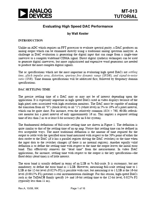
MT-013TUTORIAL Evaluating High Speed DAC Performanceby Walt KesterINTRODUCTIONUnlike an ADC which requires an FFT processor to evaluate spectral purity, a DAC produces an analog output which can be examined directly using a traditional analog spectrum analyzer. A challenge in DAC evaluation is generating the digital input that can range from a single-tone sinewave to a complex wideband CDMA signal. Direct digital synthesis techniques can be used to generate digital sinewaves, but more sophisticated and expensive word generators are needed to produce the more complex digitial signals.The ac specifications which are the most important in evaluating high speed DACs are settling time, glitch impulse area, distortion, spurious free dynamic range (SFDR), and signal-to-noise ratio (SNR). Time domain specifications will be addressed first, followed by frequency domain specifications.DAC SETTLING TIMEThe precise settling time of a DAC may or may not be of interest depending upon the application. It is especially important in high speed DACs used in video displays because of the high pixel rates associated with high resolution monitors. The DAC must be capable of making the transition from all "0"s (black level) to all "1"s (white level) in 5% to 10% of a pixel interval, which can be quite short. For instance, even the relatively common 1024 × 768, 60-Hz refresh-rate monitor has a pixel interval of only approximately 16 ns. This implies a required settling time of less than 2 ns to at least 8-bit accuracy (for an 8-bit system).The fundamental definitions of full-scale settling time are shown in Figure 1. The definition is quite similar to that of the settling time of an op amp. Notice that settling time can be defined in two acceptable ways. The more traditional definition is the amount of time required for the output to settle with the specified error band measured with respect to the 50% point of either the data strobe to the DAC (if it has a parallel register driving the DAC switches) or the time when the input data to the switches changes (if there is no internal register). Another equally valid definition is to define the settling time with respect to the time the output leaves the initial error band. This effectively removes the "dead time" from the measurement. In video DAC applications, for instance, settling time with respect to the output is the key specification—the fixed delay (dead time) is of little interest.The error band is usually defined in terms of an LSB or % full-scale. It is customary, but not mandatory, to define the error band as 1 LSB. However, measuring full-scale settling time to 1 LSB at the 12-bit level (0.025% FS) is possible with care, but measuring it to 1 LSB at the 16-bit level (0.0015% FS) presents a real instrumentation challenge. For this reason, high-speed DACs such as the TxDAC® family specify 14- and 16-bit settling time to the 12-bit level, 0.025% FS (typically less than 11 ns).DEAD TIME RECOVERY TIME LINEAR SETTLING SLEW TIMEFigure 1: DAC Full-Scale Settling TimeMid-scale settling time is also of interest, because in a binary-weighted DAC, the transition between the 0111…1 code and the 1000…0 code produces the largest transient. In fact, if there is significant bit skew, the transient amplitude can approach full-scale. Figure 2 shows a waveform along with the two acceptable definitions of mid-scale settling time. As in the case of full-scale settling time, mid-scale settling time can either be referred to the output or to the latchFigure 2: DAC Mid-Scale Settling TimeGLITCH IMPULSE AREAIdeally, when a DAC output changes it should move from one value to its new one monotonically. In practice, the output is likely to overshoot, undershoot, or both. This uncontrolled movement of the DAC output during a transition is known as a glitch . It can arise from two mechanisms: capacitive coupling of digital transitions to the analog output, and the effects of some switches in the DAC operating more quickly than others and producing temporary spurious outputs.Capacitive coupling frequently produces roughly equal positive and negative spikes (sometimes called a doublet glitch) which more or less cancel in the longer term. The glitch produced by switch timing differences is generally unipolar, much larger, and of greater concern.Glitches can be characterized by measuring the glitch impulse area , sometimes inaccurately called glitch energy . The term glitch energy is a misnomer, since the unit for glitch impulse area is volt-seconds (or more probably µV-sec or pV-sec. The peak glitch area is the area of the largest of the positive or negative glitch areas.Glitch impulse area is easily estimated from the mid-scale settling time waveform as shown in Figure 3. The areas of the four triangles are used to calculate the net glitch area. Recall that the area of a triangle is one-half the base times the height. If the total positive area equals the total negative glitch area, then the net area is zero. The specification given on most data sheets is the net glitch area, although in some cases, the peak area may specified instead.AREA 3NET GLITCH IMPULSE AREA ≈AREA 1 + AREA 2 –AREA 3 –AREA 4AREA OF TRIANGLE =12BASE ×HEIGHTFigure 3: Glitch Impulse AreaOSCILLOSCOPE MEASUREMENT OF SETTLING TIME AND GLITCH IMPULSE AREAA wideband fast-settling oscilloscope is crucial to accurate settling time measurements. There are several considerations in selecting the proper scope. The required bandwidth can be calculated based on the rise/falltime of the DAC output, for instance, a 1-ns output risetime and falltime corresponds to a bandwidth of 0.35/t r = 350 MHz. A scope of at least 500-MHz bandwidth would be required. Preferably, the scope bandwidth should be at least three times the signal bandwidth to include the second and third harmonic components for a more accurate representation of the waveform.Modern digital storage scopes (DSOs) and digital phosphor scopes (DPOs) are popular and offer an excellent solution for performing settling time measurements as well as many other waveform analysis functions (see Reference 3). These scopes offer real-time sampling rates of several GHz and are much less sensitive to overdrive than older analog scopes or traditional sampling scopes. Overdrive is a serious consideration in measuring settling time, because the scope is generally set to maximum sensitivity when measuring a full-scale DAC output change. For instance, measuring 12-bit settling for a 1-V output (20 mA into 50 Ω) requires the resolution of a signal within a 0.25-mV error band riding on the top of a 1-V step function.From a historical perspective, older analog oscilloscopes were sensitive to overdrive and could not be used to make accurate step function settling time without adding additional circuitry. Quite a bit of work was done during the 1980s on circuits to cancel out portions of the step function using Schottky diodes, current sources, etc. References 4, 5, and 6 are good examples of various circuits which were used during that time to mitigate the oscilloscope overdrive problems.Even with modern DSOs and DPOs, overdrive should still be checked by changing the scope sensitivity by a known factor and making sure that all portions of the waveform change proportionally. Measuring the mid-scale settling time can also subject the scope to considerable overdrive if there is a large glitch. The sensitivity of the scope should be sufficient to measure the desired error band. A sensitivity of 1-mV/division allows the measurement of a 0.25-mV error band if care is taken (one major vertical division is usually divided into five smaller ones, corresponding to 0.2 mV/small division). If the DAC has an on-chip op amp, the fullscale output voltage may be larger, perhaps 10 V, and the sensitivity required in the scope is relaxed proportionally.Although there is a well-known relationship between the risetime and the settling time in a single-pole system, it is inadvisable to extrapolate DAC settling time using risetime alone. There are many higher order nonlinear effects involved in a DAC which dominate the actual settling time, especially for DACs of 12-bits or higher resolution.When making settling time measurements, is generally better to make a direct connection between the DAC output and the 50-Ω scope input and avoid the use of probes. FET probes are notorious for giving misleading settling time results. If probes must be used, compensated passive ones are preferable, but they should be used with care. Skin effect associated with even short lengths of properly terminated coaxial cable can give erroneous settling time results. In making the connection between the DAC and the scope, it is mandatory that a good low impedance ground be maintained. This can be accomplished by soldering the ground of a BNC connector to the ground plane on the DAC test board and using this BNC to connect to the scope's 50-Ω input. A manufacturer's evaluation board can be of great assistance in interfacing to the DAC and should be used if available.Finally, if the DAC output is specifically designed to drive the virtual ground of an external current-to-voltage converter and does not have enough compliance to develop a measurable voltage across a load resistor, then an external op amp is required, and the test circuit measures the settling time of the DAC/op amp combination. In this case, select an op amp that has a settling time which is at least 3 to 5 times smaller than the DAC under test. If the settling time of the op amp is comparable to that of the DAC, the settling time of the DAC can be determined, because the total settling time of the combination is the root-sum-square of the DAC settling time and the op amp settling time. Solving the equation for the DAC settling time yields:DAC Settling Time = 22)Time Settling Amp Op ()Time Settling Total (−. Eq. 1DAC DISTORTIONIf we consider the spectrum of a waveform reconstructed by a DAC from digital data, we find that in addition to the expected spectrum (which will contain one or more frequencies, depending on the nature of the reconstructed waveform), there will also be noise and distortion products.Code-dependent glitches will produce both out-of-band and in-band harmonics when the DAC is reconstructing a digitally generated sinewave as in a Direct Digital Synthesis (DDS) system. For instance, the mid-scale glitch occurs twice during a single cycle of a reconstructed sinewave (at each mid-scale crossing), and will therefore produce a second harmonic of the sinewave, as shown in Figure 4. Note that the higher order harmonics of the sinewave, which also alias back into the Nyquist bandwidth (dc to f c /2), cannot be filtered.+ FULL SCALEMIDSCALE–FULL SCALEf O= 3MHzf C= 10MSPS0 1 2 3 4 5 6 7 8 9 10f c2FREQUENCY (MHz)Figure 4: Effect of Code-Dependent Glitches on Spectral Output Although segmented DAC architectures can be used to greatly minimize the distortion caused by code-dependent glitches, the distortion can never be completely eliminated.It is difficult to predict the harmonic distortion or SFDR from the glitch area specification alone. Other factors, such as the overall linearity of the DAC, also contribute to distortion. In addition, integer ratios between the DAC sampling clock and the DAC output frequency and the cause the quantization noise to concentrate at harmonics of the fundamental thereby increasing the apparent distortion at these points.Because so many DAC applications are in communications and frequency analysis systems, practically all modern DACs are now specified in the frequency domain. The basic ac specifications include harmonic distortion, total harmonic distortion (THD), signal-to-noise ratio (SNR), total harmonic distortion plus noise (THD + N), spurious free dynamic range (SFDR), etc. In order to test a DAC for these specifications, a proper digitally-synthesized signal must be generated to drive the DAC (for example, a single or multi-tone sinewave).In the early 1970s, when ADC and DAC frequency domain performance first became important, "back-to-back" testing was popular. An ADC and its companion DAC were connected together, and the appropriate analog signal source was selected to drive the ADC. An analog spectrum analyzer was then used to measure the distortion and noise of the DAC output. This approach was logical, because ADCs and DACs were often used in conjunction with a digital signal processor placed between them to perform various functions. Obviously, it was impossible todetermine exactly how the total ac errors were divided between the ADC and the DAC. Today, however, ADCs and DACs are used quite independently of one another, so they must be completely tested on their own.Figure 5 shows a typical test setup for measuring the distortion and noise of a DAC. The first consideration, of course, is the generation of the digital signal to drive the DAC. To achieve this, modern arbitrary waveform generators (for example Tektronix AWG2021 with Option 4) or word generators (Tektronix DG2020) allow almost any waveform to be synthesized digitally in software, and are mandatory in serious frequency domain testing of DACs (see Reference 3). In most cases, these generators have standard waveforms pre-programmed, such as sinewaves and triangle waves, for example. In many communications applications, however, more complex digital waveforms are required, such as two-tone or multi-tone sinewaves, QAM, GSM, and CDMA test signals, etc. In many cases, application-specific hardware and software exists for generating these types of signals and can greatly speed up the evaluation process.* MAY BE PART OF DAC EVALUATION BOARDFigure 5: Test Setup for Measuring DAC Distortion and NoiseAnalog Devices and other manufacturers of high performance DACs furnish evaluation boards which greatly simplify interfacing to the test equipment. Because many communications DACs (such as the TxDAC®-family) have quite a bit of on-chip control logic, their evaluation boards have interfaces to PCs via the SPI, USB, parallel, or serial ports, as well as Windows®-compatible software to facilitate setting the various DAC options and modes of operation. Testing DACs which are part of a direct-digital-synthesis (DDS) system is somewhat easier because the DDS portion of the IC acts as the digital signal generator for the DAC. Testing these DACs often requires no more than the manufacturer's evaluation board, a PC, a stable clock source, and a high performance spectrum analyzer.The spectrum analyzer chosen to measure the distortion and noise performance of the DAC should have at least 10-dB more dynamic range than the DAC being tested. The "maximum intermodulation-free range" specification of the spectrum analyzer is an excellent indicator of distortion performance (see Reference 7). However, spectrum analyzer manufacturers may specify distortion performance in other ways. Modern communications DACs such as the TxDAC®-series require high performance spectrum analyzers such as the Rhode and Schwartz FSEA30 (Reference 7).As in the case of oscilloscopes, the spectrum analyzer must not be sensitive to overdrive. This can be easily verified by applying a signal corresponding to the full-scale DAC output, measuring the level of the harmonic distortion products, and then attenuating the signal by 6 dB or so and verifying that both the signal and the harmonics drop by the same amount. If the harmonics drop more than the fundamental signal drops, then the analyzer is distorting the signal.In some cases, an analyzer with less than optimum overdrive performance can still be used by placing a bandstop filter in series with the analyzer input to remove the frequency of the fundamental signal being measured. The analyzer looks only at the remaining distortion products. This technique will generally work satisfactorily, provided the attenuation of the bandstop filter is taken into account when making the distortion measurements. Obviously, a separate bandstop filter is required for each individual output frequency tested, and therefore multi-tone testing is cumbersome.Finally, there are a variety of application-specific analyzers for use in communications, video, and audio. In video, the Tektronix VM-700 and VM-5000 series are widely used (Reference 3). In measuring the performance of DACs designed for audio applications, special signal analyzers designed specifically for audio are preferred. The industry standard for audio analyzers is the Audio Precision, System Two (see Reference 8). There are, of course, many other application-specific analyzers available which may be preferred over the general-purpose types. In addition, software is usually available for generating the various digital test signals required for the applications.Once the proper analyzer is selected, measuring the various distortion and noise-related specifications such as SFDR, THD, SNR, SINAD, etc., is relatively straightforward. The analyzer resolution bandwidth must be set low enough so that the harmonic products can be resolved above the noise floor. Figure 6 shows a typical spectral output where the SFDR is measured.f c dB2NOISE FLOORFigure 6: Measuring DAC Spurious Free Dynamic Range (SFDR)Figure 7 shows how to measure the various harmonic distortion components with a spectrum analyzer. The first nine harmonics are shown. Notice that aliasing causes the 6th , 7th , 8th , 9th , and 10th harmonic to fall back inside the f c /2 Nyquist bandwidth.c 2BW = ANALYZER RESOLUTION BANDWIDTH SNR = S/(NOISE FLOOR) –10 log 10f c /2BW dBNOISE FLOORFigure 7: Measuring DAC Distortion and SNR with an Analog Spectrum AnalyzerThe harmonics of the input signal can be distinguished from other distortion products by their location in the frequency spectrum. Figure 8 shows a 7-MHz input signal sampled at 20 MSPS and the location of the first 9 harmonics. Aliased harmonics of f o fall at frequencies equal to |±Kf c ± nf o |, where n is the order of the harmonic, and K = 0, 1, 2, 3,.... The second and thirdharmonics are generally the only ones specified on a data sheet because they tend to be the largest, although some data sheets may specify the value of the worst harmonic. An interactive Harmonic Image Calculator applet is available on the Analog Devices' Design Center website which shows the locations of the second and third harmonics as a function of output frequency and DAC update rate. In addition, the tool shows the attenuation effects of the sin x/x rolloff and the output anti-imaging filter.12345678910FREQUENCY (MHz)Figure 8: Location of First 9 Harmonic Products: OutputSignal = 7 MHz, DAC Update Rate = 20 MSPSDAC NOISEThe spectrum analyzer can also be used to measure SNR if the proper correction factors are taken into account. Figure 7 shows the analyzer sweep bandwidth, BW, which in most cases will be considerably less than f c/2. First, measure the noise floor level with respect to the signal level at a point in the frequency spectrum which is relatively free of harmonics. This corresponds to the value "S/(NOISE FLOOR)" in the diagram. The actual SNR over the dc to f c/2 bandwidth is obtained by subtracting the process gain, 10log10(f c/2·BW), from the S/(NOISE FLOOR).SNR = S/(NOISE FLOOR) – 10log10(f c /2·BW). Eq. 2In order for this SNR result to be accurate, one must precisely know the analyzer bandwidth. The bandwidth characteristics of the analyzer should be given out in the manufacturer's documentation. Also, if there is any signal averaging used in the analyzer, that may affect the net correction factor.In order to verify the process gain calculation, several LSBs can be disabled—under these conditions, the SNR performance of the DAC should approach ideal. For instance, measuring the 8-bit SNR of a low distortion, low noise 12-, 14-, or 16-bit DAC should produce near theoreticalresults. The theoretical 8-bit SNR, calculated using the formula SNR = 6.02N + 1.76 dB, is 50 dB. The process gain can then be calculated using the formula:PROCESS GAIN = S/(NOISE FLOOR) – SNR. Eq. 3The accuracy of this measurement should be verified by enabling the 9th bit of the DAC and ensuring that the analyzer noise floor drops by 6 dB. If the noise floor does not drop by 6 dB, the measurement should be repeated using only the first 6 bits of the DAC. If near theoretical SNR is not achieved at the 6-bit level, the DAC under consideration is probably not suitable for ac applications where noise and distortion are important.The relationship between SINAD, SNR, and THD can be derived as follows. THD is defined as the ratio of the signal to the root-sum-square (rss) of a specified number harmonics of the fundamental signal. IEEE Std. 1241-2000 (Reference 9) suggests that the first 10 harmonics be included. Various manufacturers may choose to include fewer than 10 harmonics in the calculation. Analog Devices defines THD to be the root-sum-square of the first 6 harmonics (2nd , 3rd , 4th , 5th , and 6th ) for example. In practice, the difference in dB between THD measured with 10 versus 6 harmonics is less than a few tenths of a dB, unless there is an extreme amount of distortion. The various harmonics, V2 through V6, are measured with respect to the signal level, S, in dBc. They are then converted into a ratio, combined on an rss basis, and converted back into dB to obtain the THD.The signal-to-noise-and-distortion, SINAD, can then be calculated by combining SNR and THD as a root-sum-square:()()220/THD 220/SNR 101010log 20SINAD −−+=.Eq. 4An SNR/THD/SINAD Calculator applet is available on the Analog Devices' Design Center website to assist in these conversions.One of the most important factors in obtaining accurate distortion measurements is to ensure that the DAC output frequency, f o is not a sub-harmonic of the update rate, f c . If f c /f o is an integer, then the quantization error is not random, but is correlated with the output frequency. This causes the quantization noise energy to be concentrated at harmonics of the fundamental output frequency, thereby producing distortion which is an artifact of the sampling process rather than nonlinearity in the DAC. It should be noted that these same artifacts can occur in evaluating ADCs.To illustrate this point, Figure 9 shows simulated results for an ideal 12-bit DAC where 9A shows the output frequency spectrum for the case of f c /f o = 40. Notice that the SFDR is approximately 77 dBc. The right-hand spectral output (9B) shows the case where the f c /f o ratio is a non-integer—the quantization noise is now random, and the SFDR is 93 dBc.f c= 80.000 MSPS, f o= 2.000 MHz fc= 80.000 MSPS, f o= 2.111 MHz0510152025303540 FREQUENCY -MHz 0510152025303540 FREQUENCY -MHz0−50−100−150−200−50−100−150−200(A) CORRELATED NOISE(B) UNCORRELATED NOISESFDR = 77 dBc SFDR = 93 dBcSNR = 74 dBc SNR = 74 dBcFigure 9: Correlated (A) and Uncorrelated (B) Quantization Noise Spectrum of anIdeal 12-Bit DACBecause of the wide range of possible clock and output frequencies, Analog Devices offers special fast-turnaround measurements on TxDACs for specific customer test vectors. This important service allows system designers to do advance frequency planning to ensure optimum distortion performance for their application.In lieu of specific frequency measurements, the SFDR performance of a DAC is often plotted as a function of the output frequency at fixed clock rates. This data is usually taken for sinewave outputs of various amplitudes as shown in Figure 10 for the AD9777 16-bit TxDAC. Note that this plot does not include data points where there is strong correlation between the quantization noise and the signal (i.e., where the ratio of the clock frequency to the output frequency is an integer number).DAC OUTPUT FREQUENCY (MHz)Figure 10: AD9777 16-bit TxDAC™ SFDR, Data Update Rate = 160 MSPSThere is another useful test method that gives a good overall indicator of the DAC performance at various combinations of output and clock frequencies. Specifically, this involves testing distortion for output frequencies, f o , equal to f c /3 and f c /4. In practice, the output frequency is slightly offset by a small amount, Δf, where Δf is a non-integer fraction of f c , i.e., Δf = kf c , where k << 1. For an output frequency of f c /3 – Δf, the even-order harmonics are spaced at intervals of Δf around the fundamental f o output frequency as shown in Figure 11. The worst even-order harmonic is measured at various clock frequencies up to the maximum allowable while maintaining this same ratio. The same procedure should be repeated for an output frequency f c /4 – Δf, in which case the odd-order harmonics are uniformly spaced around the output frequency as shown in Figure 12.c 3f = fc –Δf Figure 11: Location of Even Harmonics for f o = f c /3 – Δfc 4f = f c–ΔfFigure 12: Location of Odd Harmonics for f o = f c /4 – ΔfThese measurements are relatively easy to make, since once the ratio of f o to f c is established by the DDS or digital waveform generator, it is preserved as the master clock frequency is changed. Figure 13 shows a typical plot of SFDR versus clock frequency for a low distortion DAC with two output frequencies f c /3 and f c /4. In most cases, the f c /3 distortion represents a worst case condition and is good for comparing various DACs.SFDR(dBc)CLOCK FREQUENCY (MHz) 8070605040Figure 13: Worst Harmonic vs. Clock Frequency forf o = f c /3 – Δf and f o = f c /4 – ΔfDAC OUTPUT SPECTRUM AND SIN (X)/X FREQUENCY ROLLOFFThe output of a reconstruction DAC can be represented as a series of rectangular pulses whose width is equal to the reciprocal of the clock rate as shown in Figure 14. Note that the reconstructed signal amplitude is down 3.92 dB at the Nyquist frequency, f c /2. An inverse sin(x)/x filter can be used to compensate for this effect in most cases and is usually designed as part of the anti-imaging filter. The images of the fundamental signal occur as a result of the sampling function and are also attenuated by the sin(x)/x function.0.5f cf c1.5f c2f c2.5f c3f c1fAtSAMPLED SIGNALFigure 14: DAC sin(x)/x Roll Off (Amplitude Normalized)If there is no compensation for the sin(x)/x rolloff, it must be considered when making bandwidth measurements on the DAC output. The effect of the rolloff on distortion and SNR measurements is negligible over the Nyquist bandwidth, dc to f c /2.An interactive Harmonic Image Calculator applet is available on the Analog Devices' Design Center website which shows the locations of the second and third harmonics as a function of output frequency and DAC update rate. In addition, the tool shows the attenuation effects of both the sin(x)/x rolloff and the output anti-imaging filter.REFERENCES1.Jim R. Naylor, "Testing Digital/Analog and Analog/Digital Converters," IEEE Transactions on Circuitsand Systems, Vol. CAS-25, July 1978, pp. 526-538.2.Dan Sheingold, Analog-Digital Conversion Handbook, 3rd Edition, Analog Devices and Prentice-Hall,1986, ISBN-0-13-032848-0. (the defining and classic book on data conversion).3.Tektronix, Inc.,14200 SW Karl Braun Drive, P. O. Box 500, Beaverton, OR 97077, Phone: (800) 835-9433, . (the website contains a wealth of information on oscilloscopes, measurement techniques, probing, etc., as well as complete specifications on products).4.Howard K. Schoenwetter, "High Accuracy Settling Time Measurements," IEEE Transactions onInstrumentation and Measurement, Vol. IM-32, No. 1, March 1983, pp. 22-27.5.James R. Andrews, Barry A. Bell, Norris S. Nahman, and Eugene E. Baldwin, "Reference Waveform FlatPulse Generator," IEEE Transactions on Instrumentation and Measurement, Vol. IM-32, No. 1, March 1983, pp. 27-32.6.Barry Harvey, "Take the Guesswork out of Settling-Time Measurements," EDN, September 19 1985, pp.177-189.7.Rohde & Schwarz, Inc., 8661A Robert Fulton Dr., Columbia, MD 21046-2265, Phone: (410) 910-7800,. (a premier manufacturer of spectrum analyzers, the website contains tutorials on frequency analysis as well as product specifications).8.Audio Precision, 5750 S.W. Arctic Drive, Beaverton, Oregon 97005, . (therecognized industry standard for professional audio measurement equipment).9.IEEE Std. 1241-2000, IEEE Standard for Terminology and Test Methods for Analog-to-Digital Converters,IEEE, 2001, ISBN 0-7381-2724-8.10.Walt Kester, Analog-Digital Conversion, Analog Devices, 2004, ISBN 0-916550-27-3, Chapter 2 and 5.Also available as The Data Conversion Handbook, Elsevier/Newnes, 2005, ISBN 0-7506-7841-0, Chapter2 and 5.Copyright 2009, Analog Devices, Inc. All rights reserved. Analog Devices assumes no responsibility for customer product design or the use or application of customers’ products or for any infringements of patents or rights of others which may result from Analog Devices assistance. All trademarks and logos are property of their respective holders. Information furnished by Analog Devices applications and development tools engineers is believed to be accurate and reliable, however no responsibility is assumed by Analog Devices regarding technical accuracy and topicality of the content provided in Analog Devices Tutorials.。


基于高速DDFS的高精度DAC的设计张涛;万书芹;苏小波;于宗光【摘要】设计了一种应用于高速数字频率合成器的高精度DAC.电路采用6+8分段式电流舵结构进行设计,高6位为温度计编码,低8位为二进制编码,设计中采用Q2旋转漫游算法排布电流源阵列,双路归零编码控制输出.基于SMIC O.13 μm1P6M数模混合CMOS工艺设计实现,芯片面积2.66×2.54 mm2,测试结果积分非线性误差INL≤1.5 LSB,微分非线性误差DNL≤0.8 LSB,在1GHz时钟采样频率,401 MHz输出频率处,SFDR为88 dBc.【期刊名称】《中国电子科学研究院学报》【年(卷),期】2015(010)006【总页数】4页(P632-635)【关键词】数模转换器;电流舵;双路归零;INL、DNL【作者】张涛;万书芹;苏小波;于宗光【作者单位】中国电子科技集团公司第58研究所,江苏无锡214035;中国电子科技集团公司第58研究所,江苏无锡214035;中国电子科技集团公司第58研究所,江苏无锡214035;中国电子科技集团公司第58研究所,江苏无锡214035【正文语种】中文【中图分类】TN4数模转换器(DAC)是一种用于将输入的多位数字信号转换为模拟信号输出的器件,作为数字信号领域与模拟信号领域的接口得到广泛应用。
高速高精度DAC器件更是成为现代电子系统中不可或缺的重要组件,民用领域可应用于无线基站、自动控制、医疗电子、视频显示、宽带通讯等,在国防军事领域也广泛用在雷达、通讯、电子战等各个方面[1,2]。
近年来随着数字技术的飞速发展,对于高速高精度的DAC的需求更是迫切。
我国从70年代起开始研究DAC技术,虽然开发出DAC有百余款,但是真正得到大批量市场应用的并不多,开展高精度DAC的研究工作,缩短与国外技术差距,无论是对于国民生产还是国防建设都起着重大推动作用。
文中介绍了基于0.13μm工艺设计的一款高速,高精度、高稳定性DAC,电路经测试及上机试用,各项技术指标达到预期设计目标,性能稳定。

一种16位电流舵DAC的高精度前台校准方法
张妍;蒲佳;何善亮;何浩江;曹文涛
【期刊名称】《固体电子学研究与进展》
【年(卷),期】2024(44)2
【摘要】基于28 nm CMOS工艺,采用一种高精度的前台校准技术设计了一款16 bit电流舵数模转换器(Digitalto-analog converter,DAC)电路。
该前台校准算法对16 bit数据对应的所有电流源进行校准,并且使用的电流源只有两种大小,降低校准难度的同时也提升了校准的精度。
该校准电路引入了两种校准补充电流,分别用于温度和输出电流变化引起电流源失配的补偿,进一步减小了DAC电流源的失配,有效提高了DAC的整体性能。
采用校准后,在-40~85℃温度范围内,微分非线性
≤0.8 LSB,积分非线性≤2.0 LSB,200 MHz输出信号下无杂散动态范围≥75.3 dB。
该校准方法提高了DAC的温度稳定性。
【总页数】6页(P143-148)
【作者】张妍;蒲佳;何善亮;何浩江;曹文涛
【作者单位】西安电子科技大学;成都振芯科技股份有限公司
【正文语种】中文
【中图分类】TN432
【相关文献】
1.一种带斐波那契译码的高精度电流舵DAC
2.基于电流舵的高精度低功耗13-bits DAC设计
3.用于高性能电流舵型DAC的数字校准模块
4.一种应用于14 bit 200 MS/s电流舵型DAC的数字校准技术
5.基于高精度电流源的10bit电流舵DAC
因版权原因,仅展示原文概要,查看原文内容请购买。

高速ADC/DAC的测试方法演讲内容大家好,我是今天做分享的任彦楠,非常荣幸能和大家交流,今天我分享的内容是within 我的knowledge, 也希望将我不懂的地方向大家请教。
今天我要和大家分享的是高速ADC/DAC的测试方法~ADC主要的测试指标分为静态指标和动态指标两类:静态指标,包括INL、DNL;动态指标,主要是基于SFDR,在此基础之上计算的ENOB(有效位数)。
尽量言简意赅吧。
ADC的测试方法,其实简单来说,就是输入和输出,输入怎么给?输出怎么测?怎么计算?以及换算到spec。
输入主要是两部分:数据和clk。
大家知道ADC的数据和clk都用什么给信号吗?听众答:ADC的数据是指输入的模拟信号吗?任老师:哈哈,是的,信号发生器;然而对于ADC,尤其是高精度的ADC,最关键的是信号源的选择,这里需要的是高精度的信号源,也就是说信号源的动态范围要高于被测ADC两个精度位以上,这是关键之一。
第二,就是信号源和clk的同步。
接着,我们来看输出,ADC输出的是digital信号,也就是说输出采样到的是数字信号。
但是ADC的动态参数表示都是基于频谱分析的方法。
也就是说要将输出、采样到的数字信号用FFT变换到频域,这就是大家看到ADC的测试程序为什么主函数是FFT 函数的原因。
我记得我们当时实验室测得,10bit以上ADC,都至少是1024点。
听众问:或者转到频域,频率精度到什么精度才合适?任老师:实测的时候,你有时会发现,FFT点数选的少,测试结果会好,不知大家有没有碰到过这种情况?嗯,但其实这是一种假象。
你想10bit ADC输出的全位分辨率就是1024,如果没有采到1024个点,说明丢失了部分数据,不能真实反映ADC的性能。
所以大家测。