ETH-PPI以太网转换器操作手册
- 格式:doc
- 大小:1.09 MB
- 文档页数:23

ETH-PPI(CP243i)使用说明CP243i(ETH-PPI)以太网转换器使用手册概述:CP243i是西门子S7—200 PLC专用以太网转换器,使用方便,对用户完全透明,无需在上位机和PLC中添加任何程序和驱动,安装后立即可以使用。
它将西门子S7—200的PPI 协议转换为西门子的Profinet协议(TCP/IP)使西门子S7—200可以通过以太网与各种上位软件实现远距离、高速(最高可达187.5K)通讯,并可以同时连接 Step7-MicroWin对西门子S7-200 进行编程。
它可以通过Internet实现跨地域数据传送。
它与西门子以太网通讯处理器CP243—1功能相似,可代替西门子PPI rs232 cable、USB-PPI、CP243-1。
一、硬件连接方式:网线准备:直通线:计算机通过交换机(或HUB)、路由器和模块相连,可用于一台或多台计算机与一台或多台PLC相连。
同一根网线的两端使用同样的线序;交叉线:直接将模块与单台计算机相连时:即一台PLC和一台上位机,用交叉线(RJ45 网线)相连。
网线的线序又分为两种:568A与568B。
在实际运用中一般都使用568B,通常认为568B对电磁干扰的屏蔽比较好。
标准568B线序:1-橙白,2-橙,3-绿白,4-蓝,5-蓝白,6-绿,7-棕白,8-棕;自行压制网线时,须特别需要注意RJ45水晶头引脚序号,当金属片面对我们的时候从左至右引脚序号是1~8。
双绞线的顺序与RJ45头的引脚序号要—一对应。
而交叉线的线序在直通线的基础上做了一点改变:就是在线缆的一端把1和3对调,2和6对调。
即交叉线的一端保持原样(直通线序)不变,在另一端把1和3对调,2和6对调。
交叉线两端的线序如下:一端(不变) 另一端(对调两根)线序是从左边起:橙白-橙-绿白-蓝-蓝白-绿-棕白-棕。
另一端线序为绿白- 绿- 橙白--蓝--蓝白---橙--棕白--棕在连接设备时,网线的标准通讯距离为100米,较长时可在中间加一个交换机,起到中继的作用;较远距离时,须加装一对光纤收发器和光缆。
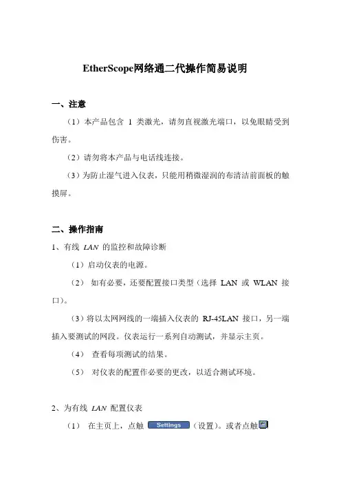
EtherScope网络通二代操作简易说明一、注意(1)本产品包含1 类激光,请勿直视激光端口,以免眼睛受到伤害。
(2)请勿将本产品与电话线连接。
(3)为防止湿气进入仪表,只能用稍微湿润的布清洁前面板的触摸屏。
二、操作指南1、有线LAN 的监控和故障诊断(1)启动仪表的电源。
(2)如有必要,还要配置接口类型(选择LAN 或WLAN 接口)。
(3)将以太网网线的一端插入仪表的RJ-45LAN 接口,另一端插入要测试的网段。
仪表运行一系列自动测试,并显示主页。
(4)查看每项测试的结果。
(5)对仪表的配置作必要的更改,以适合测试环境。
2、为有线LAN 配置仪表(1)在主页上,点触(设置)。
或者点触EtherScope 网络通图标,它位于标题栏的左上角。
从下拉列表中,点触仪表设置。
会显示仪表设置— TCP/IP 屏幕(仪表设置-TCP/IP 屏幕)。
在该该屏幕上,可以配置仪表的TCP/IP 设置。
(2)点触预览窗格中的超链接以显示其它配置屏幕,这些屏幕在TCP/IP 设置、管理TCP/IP、802.1Q/IP TOS 设置、802.1X 设置、主动测试、SNMP、连接日志、以太网设置、仪表安全设置、常规设置等部分加以描述。
(3)设置好后按保存设置,仪表以新设置开始测试。
3、光纤局域网故障诊断(1)安装SFP 光纤适配器:在仪表处于关机状态时,将保护罩卸下。
将光纤适配器插入,要确保它可靠地插入接口。
(卸除SFP 光纤适配器时:应确保仪表已关闭,并按下适配器背面上的释放卡扣。
)(2)启动仪表的电源。
仪表运行一系列自动测试,并显示主页。
注意:如果RJ-45 铜缆和SFP 光纤(SX,LX 或ZX)适配器同时连接到网络,当仪表尝试建立链接时,光纤连接要优先于铜缆连接。
当EtherScope 连接到千兆光纤接口时,它支持所有现有的局域网特性,但下列情况除外:(1)连接速度显示1000MB 及光纤类型(SX,LX 或ZX)(2)“线缆验证”和“信号验证”测试由光纤损耗测试取代4、运行诊断测试可以用以下两种方法之一访问诊断测试:(1)点触并从下拉列表中选择需要的测试。

大连德嘉国际ETH-PPI以太网转换器使用手册概述:大连德嘉电子的2011款ETH—PPI=CP243i+wincc直连功能(即不用PC ACCESS )。
它能够使你用WinCC自带的驱动[TCP/IP(auto)]连接S7-200 。
在工程应用中化复杂为简单、方便实用。
减少了因使用OPC[即PC ACCESS]而带来的通讯不稳定性!WinCC中的I、 QM、 DB1(切记是DB1)与 s7-200中的 I、 Q 、M、 V一一对应,使用时非常简单,填完IP 地址就可立即使用。
同时S7-200的编程软件MicroWin 4.0 也可同时工作,可通过 ETH-PPI 对s7-200进行上传下载程序,在线调试及监视,功能是相当的强大,西门子不能同时做到!另外,西门子Prodave 6.0 是无法与S7-200连接的,但通过ETH-PPI转换器,走S7-300 TCP协议是完全可行的!这为喜欢编程的客户(尤其是在数据采集项目中)提供解决问题的最好手段!优势:1、连接wincc不需要用OPC,可以直接连接,增强通讯稳定性。
2、可以利用西门子Prodave 6.0 和VB开发自己的S7-200用上位软件。
注:如果您不需要wincc直连或者用Prodave开发自己的S-200上位软件,您可以选择我们的CP243i,因为它的价格相对会便宜一些。
导轨型ETH-PPI:可以同时导轨安装和螺钉安装。
简约型ETH-PPI:功能同上,只是外形较为小巧电源24V,PPI口供电,严禁外接电源保护类型电感线圈隔离电缆长度标配:50cmPPI线(注:不配网线)尺寸(长X宽X高)mm导轨型:80x71x62:简约型:76X34X28一、硬件连接方式:1)线型方式:即一台PLC(s7-200和一台上位机(计算机),直接用交叉线(RJ45 网线)相连。
2)星型方式:即一台PLC(s7-200)和两台上位机(计算机)或多台PLC(S7-200)和一台上位机(计算机)或多台PLC(s7-200)和两台上位机(计算机),中间需加以太网交换机,用直联线(RJ45 网线)将交换机与各设备相连。

EtherNetIP APP 使用说明书 资料版本:V1.1—2019.9声明首先非常感谢您选择本公司产品!在使用前,请您仔细阅读本用户手册。
非本公司书面许可,任何单位和个人不得擅自摘抄、复制本书内容的部分或全部,并不得以任何形式传播。
由于不断更新,本公司不能承诺该资料与实际产品一致, 同时也不承担由于实际技术参数与本资料不符所导致的任何争议,任何改动恕不提前通知。
本公司保留最终更改权和解释权。
版权所有©2019北京映翰通网络技术股份有限公司及其许可者版权所有,保留一切权利。
本手册图形界面约定格 式意 义表示按钮名,如“单击确定按钮”。
“” “”表示窗口名、菜单名,如:弹出“新建用户”窗口。
>>多级菜单用“>>”隔开。
如“文件>>新建>>文件夹”多级菜单表示“文件”菜单下的“新建”子菜单下的“文件夹”菜单项。
提醒操作中应注意的事项,不当的操作可能会导致数据丢失或者设备损坏。
对操作内容的描述进行必要的补充和说明。
技术支持联络信息北京映翰通网络技术股份有限公司(总部)地址:北京市朝阳区利泽中园103号楼3层302电话:(8610)6439 1099 传真:(8610)8417 0089成都办事处地址:四川省成都市高新区府城大道西段399号,天府新谷10栋1406室广州办事处地址:广州市天河区棠东东路5号远洋新三板创意园B-130单元武汉办事处 地址:湖北省武汉市洪山区珞瑜东路2号巴黎豪庭11栋2001室 上海办事处 电话: ************地址:上海市普陀区顺义路18号1103室目 录1 概述 (1)2 准备项 (2)2.1 软件 (2)2.2 接线 (2)3 配置PLC (3)3.1 新建项目 (3)3.2 添加设备 (3)3.3 设备组态 (4)3.4 导入或编写程序 (7)3.5 下载程序 (8)4 配置网关 (11)4.1 升级系统固件 (11)4.2 升级PySDK (11)4.3 启用Python APP管理 (12)4.4 运行EtherNetIP APP (12)4.5 配置EtherNetIP APP变量表 (14)4.6 开启设备远程监控平台 (17)5 登录云平台查看采集数据 (19)6 附录 (20)6.1 测试通信 (20)6.2 配置文件 (21)6.2.1 配置文件示例 (21)6.2.2 配置文件详解 (21)1概述伴随着信息技术的飞速发展,各种数据采集系统广泛应用于工业、农业、国防科技和人工智能等领域中,对其准确度、存储大小以及控制方法等技术指标的要求越来越严格,绝大多数数据需要实时传输。

转换器使用说明书亲爱的用户,感谢您选择本公司的产品和服务。
对技术完美性的追求是我们的目标,我们的理念是产品不求多,只求精。
请您在使用本机前详细阅读此说明书,以便方便您安装使用。
注意:本手册未经本公司的许可,不得任意复制、拷贝、翻译或以其他形式进行发送。
本手册所提及的商标和名称皆属本公司所有。
未经本公司许可而对产品及本说明书进行修改所造成的产品功能不实现、损伤或对其他产品、人造成的影响,本公司将不负任何责任。
对于以合法渠道取得本公司产品的用户,本公司将提供三个月保换、一年保修的服务,但不包括操作不当,人为原因的故障及伤害。
本手册若有任何内容修改或变更,将不另行通知。
XX年X月版本:V4.0一、系统简介XX转换器型设备1~8条E1电路点对点地传输以太网MAC帧数据,设计最高传输速率可达16.384Mbps。
设备不仅提供了线路侧、以太网侧完备的告警指示,而且提供了包括线路的误码率统计,以太网数据流量统计等全面的管理信息,便于构建可统一运营的接入网。
二、技术特性1,实现1-8路E1通道承载100M以太网数据。
2,以太网接口标准的MII接口,只支持100M,全双工工作模式;内置流量统计,可汇报给网管以太网收发的流量统计和错包率等信息;对超长、超短和CRC错包进行过滤;最大支持2036字节的超长包;支持PAUSE流量控制功能;可通过以太网进行管理(可选)3,线路接口1-8路E1通道。
必须成对使用,但可以不对称使用;自动检测可用通道数目,该通道数据也可以通过网管关断;具有AIS、LOS、LOF和误码率告警,其中误码率的具体数据可以通过网管查询;误码关断及误码门限可由网管设置;支持远端环回,支持线路通道误码检测(利用HDLC控制帧);发起远端环回时,禁止向以太网侧发送数据;可检测外部E1环回,禁止向以太网侧发送数据;XX码型4,网管支持XX网管。
可通过以太网进行管理;8bits设备地址输入,最多统一管理256个设备网管信息全面,包括本端和远端的各E1线路状态,以太网端口信息和流量统计。
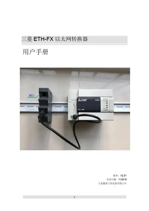
三菱ETH-FX以太网转换器用户手册版本:V2.01发布日期:11/2019大连德嘉工控设备有限公司该ETH-FX以太网转换器有两种型号:下面型号为:ETH-FX-1LAN,(带有1个网口)下面型号为:ETH-FX-2LAN,(带有2个网口,具有交换机功能)目录1.产品概述 (4)2.参数设置 (5)3.连接编程软件 (7)4.连接组态王 (13)5.连接力控 (17)6.连接Kepware OPC (19)7.连接WinCC (23)ETH-FX以太网转换器使用说明一、产品概述大连德嘉推出三菱FX系列PLC以太网转换器是一款经济型的以太网通讯处理器,通过它就可以直接升级为带有以太网口的PLC了,省去了编程电缆,用于三菱系列PLC以太网数据采集,如:型号为FX1N/1S/2N/3S/3G/3GC/3U/3UC,可通过它直接与编程软件GX Works2/上位机(组态王、力控、KepWare OPC、WinCC)或触摸屏(步科、昆仑通态、威纶、三菱系列触摸屏)通讯。
ETH-FX以太网转换器采用导轨式设计,35mm导轨安装,无需供电,它是通过连接编程口的电缆,由PLC供电。
将三菱FX系列PLC的MD8编程通讯口转成以太网,即上位机或触摸屏通过以太网对PLC数据监控。
本产品最多可同时连接四台上位机(包括触摸屏)其中CPU型号为FX1S不建议使用,通过测试后能连接上,但是由于其支持的最高波特率为9600,所以以太网通讯速度很慢。
应用:可通过以太网编程、上下载程序、上位监控(组态王、力控、KepWare OPC、WinCC)组网方式(型号:ETH-FX-1LAN)为例:二、参数设置该三菱ETH-FX以太网转换器,内部有一个IP地址(出厂预设为192.168.1.10),它还预留了一个后门地址192.168.1.222(注:并不是转换器的真实地址),用于当用户忘记实际的IP地址后,通过在IE浏览器中地址栏输入:192.168.1.222来进入内部参数设置页面,来查看或设置转换器的内部实际设置值,如图:(1)ETH-FX以太网转换器IP地址设置将ETH-FX以太网转换器与计算机用网线连接好,将计算机IP地址设置为(如:192.168.1.100),掩码(255.255.255.0),网关(192.168.1.1),最后在计算机的IE浏览器中输入:192.168.1.222,就可进入主菜单,然后点击“转换器IP/MAC设置”,进入查看或更改IP地址。
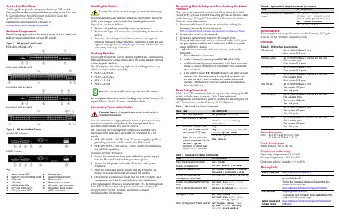
How to Use This GuideUse this guide to quickly set up your Enterasys ®B5 switch.Enterasys Networks recommends that you refer to the Enterasys B5 Gigabit Ethernet Switch Hardware Installation Guide for specifications and safety warnings.The latest B5 documentation is located at /support/manuals.Hardware ComponentsThe following figures show the several types of front panel port and rear panel connections on your B5 switch.Figure 1B5 Switch Front PanelsB5G124-24, B5G124-24P2B5G124-48, B5G124-48P2B5K125-24, B5K125-24P2B5K125-48, B5K125-48P2Figure 2 B5 Switch Back PanelsNon-PoE B5 SwitchesPoE B5 SwitchesKey1Switch status LEDs8Console port2RJ45 10/100/1000 Mbps ports 9Stack connection ports 3SFP slots 10Rotary switch410G slots11Password reset button 5RJ45 status LEDs 12AC power input connector 6SFP port status LEDs 13Redundant power supply 710G port status LEDs(RPS) connectorHandling the SwitchTo prevent electrostatic damage, attach an electrostatic discharge (ESD) wrist strap to your wrist before handling the switch.Unpack the switch as follows:1.Remove the packing material protecting the switch.2.Remove the tape seal on the non ‐conductive bag to remove theswitch.3.Perform a visual inspection of the switch for any signs ofphysical damage. Contact Enterasys Networks if there are any signs of damage. See “Getting Help” for more information on contacting Enterasys Networks.Stacking SwitchesUp to eight B5 switches can be stacked together and connected by high ‐speed stacking cables, which allow the entire stack to operate with a single IP address.The B5 supports the following high ‐speed stacking cables only, which you must order separately:•STK ‐CAB ‐SHORT •STK ‐CAB ‐LONG •STK ‐CAB ‐2M •STK ‐CAB ‐5MFor complete information about stacking, refer to the Enterasys B5 Gigabit Ethernet Switch Hardware Installation Guide.Connecting Power to the SwitchYou can connect to a single, primary source of power, or to two sources of power for redundancy. The example used here describes connecting to two power sources.The following redundant power supplies are available to be purchased from Enterasys Networks for connection to a B5 switch:•STK ‐RPS ‐150PS, a 102‐156 watt DC power supply capable ofproviding power to a fully ‐loaded non ‐PoE switch.•STK ‐RPS ‐500PS, a 500 watt DC power supply recommendedfor full PoE capability.To power ‐up your B5 switch:1.Attach the power cord from your redundant power supplyinto the B5 switch’s redundant power receptacle.2.Attach the AC power cord to the B5 switch’s AC powerreceptacle.3.Plug the redundant power supply and the B5 switch ACpower cords into dedicated, grounded AC outlets.4.Once power is connected, verify that the CPU (system) LEDturns amber until the B5 switch finishes its initialization.If the initialization process is successful, the CPU LED turns green. If the CPU LED does not turn green, refer to the Enterasys B5 Gigabit Ethernet Switch Hardware Installation Guide for troubleshooting information.Caution:The switch can be damaged by electrostatic discharge.You can stack a B5 switch only with other B5 switches.Only qualified personnel should perform Completing Switch Setup and Downloading the Latest FirmwareOnce you have connected power to the B5 switch and verified LED activity, you can complete the setup process as follows. Refer to the Enterasys B5 Gigabit Ethernet Switch Hardware Installation Guide for more information.1.Determine the latest B5 firmware version by visiting theEnterasys Networks download site at:/services/support/downloads/software2.Connect the switch to the network.3.Connect a management station to the console port.4.Verify that the network devices connected to the switch portsare powered on, and that each link/activity LED is on (solid green or blinking green).5.At the device connected to the console port, perform thefollowing:a.Enter admin for Username.b.At the Password prompt, press ENTER (RETURN).c.At the command prompt, determine if the latest firmwareimage is loaded on the switch by entering this command:show versiond.If the output (under FW Version ) displays an older versionnumber than that determined in step 1, download and activate the new version as directed on the download website. (Alternatively, you can use the CLI commands listed in Table 1.)Basic Setup CommandsTable 1 lists CLI commands that are required for setting up the B5 switch with the latest firmware. Table 2 lists additionalconfiguration commands for your B5 switch. For the complete list of CLI commands, see the Enterasys B5 CLI Reference .Table 1Required CLI Setup CommandsStep TaskCLI commands1Set a new password set password [username ]2Set the switch IP addressset ip address ip-address [mask ip-mask ] [gateway ip-gateway ]3Download, activate, and verify new firmware on the switch using TFTP copyNote: You can reboot the system immediately with the set boot systemcommand, or reboot later with the reset command.copytftp://tftp_server_ip_address /filename system:image set boot system filenameshow version Table 2Optional CLI Setup CommandsTaskCLI commands Save the active configuration save configEnable or disable SSH set ssh enable | disable Enable or disable Telnet set telnet {enable | disable} [inbound | outbound | all]Enable or disable HTTP management (WebView)set webview {enable | disable}Enable or disable SNMP port link trapsset port trap port-string{enable | disable}Set the per port broadcast limit set port broadcast port-string threshold-valueConfigure a VLANset vlan create vlan-id set port vlan port-string vlan-id modify-egress Set a Syslog server IP and severity set logging server indexip-addr ip-addr severity severity state enableSpecificationsFor a complete list of specifications, see the Enterasys B5 Gigabit Ethernet Switch Hardware Installation Guide . InterfacesSwitch DimensionsSize:44.1 W x 4.4 H x 36.85 D cm 17.4 W x 1.7 H x 14.5 D inPower ConsumptionInput Voltage: 100 to 240VACTemperature and HumidityOperating temperature: 0°C to 50°C Storage temperature: ‐40°C to +70°C Operating relative humidity: 5% to 95%Getting HelpConfigure and enable a RADIUS serverset radius server index ip-addr port [secret-value ]{realm {management-access | any | network-access} set radius enableTable 3B5 Interface DescriptionsB5G124-24•24 10/100/1000Base-T ports •Four combo SFP portsB5G124-24P2•24 10/100/1000Base-T 802.3af and 802.3at PoE-capable ports •Four combo SFP portsB5G124-48•48 10/100/1000Base-T ports •Four combo SFP portsB5G124-48P2•48 10/100/1000Base-T 802.3af and 802.3at PoE-capable ports •Four combo SFP portsB5K125-24•24 10/100/1000Base-T ports •Two combo SFP ports •Two 10G portsB5K125-24P2•24 10/100/1000Base-T 802.3af and 802.3at PoE-capable ports •Two combo SFP ports •Two 10G portsB5K125-48•48 10/100/1000Base-T ports •Two combo SFP ports •Two 10G portsB5K125-48P2•48 10/100/1000Base-T 802.3af and 802.3at PoE-capable ports •Two combo SFP ports •Two 10G portsWorld Wide Web /support/Phone1-800-872-8440 (toll-free in U.S. and Canada) or 1-978-684-1888To find the Enterasys Networks Support toll-free number in your country:/services/support/contact/Internet mail*********************To expedite your message, type [Switching ] in the subject field of your message.Latest image and release notes/services/support/downloads/software/Table 2Optional CLI Setup Commands (Continued)TaskCLI commandsRelated DocumentsThe latest B5 documentation is located online at: /support/manualsWarrantyWarranty information for the B5 switch is located online at:/support/warranty.aspx/company/literature/enterasys ‐lw ‐ds.pdfNoticeEnterasys Networks reserves the right to make changes in specifications and other information contained in this document and its web site without prior notice. The reader should in all cases consult Enterasys Networks to determine whether any such changes have been made.The hardware, firmware, or software described in this document is subject to change without notice.IN NO EVENT SHALL ENTERASYS NETWORKS BE LIABLE FOR ANY INCIDENTAL,INDIRECT, SPECIAL, OR CONSEQUENTIAL DAMAGES WHATSOEVER (INCLUDING BUT NOT LIMITED TO LOST PROFITS) ARISING OUT OF OR RELATED TO THIS DOCUMENT, WEB SITE, OR THE INFORMATION CONTAINED IN THEM, EVEN IF ENTERASYS NETWORKS HAS BEEN ADVISED OF, KNEW OF, OR SHOULD HAVE KNOWN OF, THE POSSIBILITY OF SUCH DAMAGES.Enterasys Networks,Inc.50 Minuteman Road Andover, MA 01810© 2010 Enterasys Networks,Inc. All rights reserved.Part Number:9034512‐02December 2010ENTERASYS, ENTERASYS NETWORKS, ENTERASYS SECURE NETWORKS, NETSIGHT, ENTERASYS NETSIGHT, and any logos associated therewith, are trademarks or registeredtrademarks of Enterasys Networks, Inc., in the United States and/or other countries. For a complete list of Enterasys trademarks, see /company/trademarks.aspx .All other product names mentioned in this manual may be trademarks or registered trademarks of their respective companies.Regulatory Compliance InformationFederal Communications Commission (FCC) NoticeThis device complies with Part 15 of the FCC rules. Operation is subject to the following twoconditions: (1) this device may not cause harmful interference, and (2) this device must accept any interference received, including interference that may cause undesired operation.NOTE:This equipment has been tested and found to comply with the limits for a class A digital device, pursuant to Part 15 of the FCC rules. These limits are designed to provide reasonable protection against harmful interference when the equipment is operated in a commercialenvironment. This equipment uses, generates, and can radiate radio frequency energy and if not installed in accordance with the operator’s manual, may cause harmful interference to radiocommunications. Operation of this equipment in a residential area is likely to cause interference in which case the user will be required to correct the interference at his own expense.WARNING:Changes or modifications made to this device which are not expressly approved by the party responsible for compliance could void the user’s authority to operate the equipment.Industry Canada NoticeThis digital apparatus does not exceed the class A limits for radio noise emissions from digital apparatus set out in the Radio Interference Regulations of the Canadian Department of Communications.Le présent appareil numérique n’émet pas de bruits radioélectriques dépassant les limitesapplicables aux appareils numériques de la class A prescrites dans le Règlement sur le brouillage radioélectrique édicté par le ministère des Communications du Canada.Class A ITE NoticeWARNING:This is a Class A product. In a domestic environment this product may cause radio interference in which case the user may be required to take adequate measures.Clase A. Aviso de ITEADVERTENCIA: Este es un producto de Clase A. En un ambiente doméstico este producto puede causar interferencia de radio en cuyo caso puede ser requerido tomar medidas adecuadas.Klasse A ITE AnmerkungWARNHINWEIS: Dieses Produkt zählt zur Klasse A ( Industriebereich ). In Wohnbereichen kann es hierdurch zu Funkstörungen kommen, daher sollten angemessene Vorkehrungen zum Schutz getroffen werden.VCCI NoticeThis is a class A product based on the standard of the Voluntary Control Council for Interference by Information Technology Equipment (VCCI). If this equipment is used in a domestic environment, radio disturbance may arise. When such trouble occurs, the user may be required to take corrective actions.BSMI EMC Statement — TaiwanThis isa class A product. In a domestic environment this product may cause radio interference in which case the user may be required to take adequate measures.AS/NZS CISPR 22Hazardous SubstancesThis product complies with the requirements of European Directive, 2002/95/EC, Restriction of Hazardous Substances (RoHS) in Electrical and Electronic Equipment.European Waste Electrical and Electronic Equipment (WEEE) NoticeIn accordance with Directive 2002/96/EC of the European Parliament on waste electrical and electronic equipment (WEEE):1.The symbol above indicates that separate collection of electrical and electronic equipment isrequired and that this product was placed on the European market after August 13, 2005, the date of enforcement for Directive 2002/96/EC.2.When this product hasreached the end of its serviceable life, it cannot be disposed of as unsortedmunicipal waste. It must be collected and treated separately.3.It has been determined by the European Parliament that there are potential negative effects onthe environment and human health as a result of the presence of hazardous substances in electrical and electronic equipment.4.It is the users’ responsibility to utilize the available collection system to ensure WEEE is properlytreated.For information about the available collection system, please go to/services/support/or contact Enterasys Customer Support at 353 61 705586 (Ireland).Safety InformationClass 1 Laser TransceiversThe single mode interface modules use Class 1 laser transceivers. Read the following safety information before installing or operating these modules.The Class 1 laser transceivers use an optical feedback loop to maintain Class 1 operation limits. This control loop eliminates the need for maintenance checks or adjustments. The output is factory set, and does not allow any user adjustment. Class 1 Laser transceivers comply with the following safety standards:•21 CFR 1040.10 and 1040.11 U.S. Department of Health and Human Services (FDA).•IEC Publication 825 (International Electrotechnical Commission).•CENELEC EN 60825 (European Committee for Electrotechnical Standardization).When operating within their performance limitations, laser transceiver output meets the Class 1 accessible emission limit of all three standards. Class 1 levels of laser radiation are not considered hazardous.When the connector is in place, all laser radiation remains within the fiber. The maximum amount of radiant power exiting the fiber (under normal conditions) is ‐12.6 dBm or 55 x 10‐6 watts.Removing the optical connector from the transceiver allows laser radiation to emit directly from the optical port. The maximum radiance from the optical port (under worst case conditions) is 0.8 W cm ‐2 or 8 x 10³ W m 2 sr ‐1.Do not use optical instruments to view the laser output. The use of optical instruments to view laser output increases eye hazard. When viewing the output optical port, power must be removed from the network adapter.Safety ComplianceWarning: Fiber Optic Port SafetyWhen using a fiber optic media expansion module, never look at the transmit laser while it is powered on. Also, never look directly at the fiber TX port and fiber cable ends when they are poweredon.Avertissment: Ports pour fibres optiques - sécurité sur le plan optiqueNe regardez jamais le laser tant qu’il est sous tension. Ne regardezjamais directement le port TX (Transmission) à fibres optiques et les emboutsde câbles à fibres optiques tant qu ʹils sont sous tension.Warnhinweis: Faseroptikanschlüsse - Optische SicherheitNiemals ein Übertragungslaser betrachten, während dieseseingeschaltet ist. Niemals direkt auf den Faser ‐TX ‐Anschluß und auf die Faserkabelenden schauen, während diese eingeschaltet sind.Declaration of ConformityApplication of Council Directive(s):2004/108/EC2006/95/ECManufacturer’s Name:Enterasys Networks,Inc.Manufacturer’s Address:50 Minuteman RoadAndover, MA 01810USAEuropean Representative Address:Enterasys Networks Ltd.Nexus House, Newbury Business ParkLondon Road, NewburyBerkshire RG14 2PZ, EnglandConformance toDirective(s)/Product Standards:EC Directive 2004/108/ECEN 55022:2006EN 55024:1998EN 61000‐3‐2:2006EN 61000‐3‐3:1995EC Directive 2006/95/EC EN 60950‐1:2006EN 60825‐1:2007EN 60825‐2:2004Equipment Type/Environment:Information Technology Equipment,for use in a Commercialor Light Industrial Environment.Enterasys Networks,Inc. declares that the equipment packaged with this notice conforms to the above directives.Enterasys ®B5Gigabit Ethernet SwitchQuick ReferenceB5G124-24, B5G124-24P2B5G124-48, B5G124-48P2B5K125-24, B5K125-24P2B5K125-48, B5K125-48P2P/N 9034512-02。


竭诚为您提供优质文档/双击可除e1以太网协议转换器篇一:以太网转4e1协议转换器说明书以太网转4e1协议转换器说明书qs-Rj45-4e1接口转换器采用反向复用技术,将多条e1电路捆绑起来用于传输10m/100m的以太网数据,实现了1-4路e1通道至以太网接口之间的相互转换,此转换器能把e1通道收发的信号点对点传输到Rj45接口,实现e1信道与以太网的互连。
与一般的远程网桥不同的是,此转换器支持1-4路e1信道的灵活配置,能自动检测e1的数量并选择可用的e1,并且允许e1电路之间存在一定的传输时延差。
单路线路速率是1968kbit/s,4路带宽可达7872kbit/s。
设备在10/100mbps 全/半双工方式下使用时,可与以太网交换机或集线器相连,充分地利(e1以太网协议转换器)用电信网络中现有的大量e1电路资源来扩展以太网的传输距离和应用范围,是以太网宽带接入一个很好的解决方案。
此产品可用于局域网互连、局端互连、视频点播、远程监控、交换机的e1接口插卡等各种领域。
关键特性:基于自主知识产权的集成电路;实现以太网数据在1~4条e1电路中的透明传输;以太网接口10m/100m,全/半双工完全自适应,支持Vlan 协议;每路以太网口支持支持auto-mdix(交叉线和直连线自适应);可设置cRc告警门限自动对传输质量差的线路进行隔离,并且是单方向切断,当2m支路一个方向误码率超出门限时,只切断该方向,另一方向不受影响;即以太网传输的两个方向可以不对称;实允许4路e1有10ms的传输时延差。
当该差值超出允许的范围时,系统可以自动停止在时延过大的e1上发送数据;真正实现snmp的网管功能;提供2种环回功能:e1本端自环、e1向外环;内置动态以太网mac地址列表(4096个),具有本地数据帧过滤功能;e1接口符合itu-tg.703、g.704和g.823,不支持信令时隙的使用;e1接口模块含有内置的时钟恢复电路和hdb3编解码电路;设备工作中支持e1信道的热插拔,并自动检测有效的e1信道,中间不会中断数据传输;支持1至4路e1的灵活配置,在复位时自动检测e1的数量和时延并选择可用的e1;支持本地系统对远端系统的复位;有以太网监控自动复位功能,不会死机;网管接口采用snmp。
—ABB MEASUREMENT & ANALYTICS | DATA SHEETTEIP11I/P signal converter for standard signals2 TEIP11 I/P SIGNAL CONVERTER FOR STANDARD SIGNALS | DS/TEIP11-EN REV. DTEIP11 I/P SIGNAL CONVERTER FOR STANDARD SIGNALS | DS/TEIP11-EN REV. D 3—ConceptThe TEIP11 signal converter converts standard electrical signals, e.g. 4 to 20 mA to 0.2 to 1 bar (3 to 15 psi). It is therefore a connecting link between electrical/electronic and pneumatic systems. The signal conversion process is similar to the patented force balance method.Special features of the TEIP11 signal converter are its relatively small dimensions and outstanding operational stability when subject to shock and vibration. The converter can be subjected to loads up to 10 g with less than 1% effect on function.The housing units are available in a variety of models to meet your installation requirements. For potentially explosive conditions, units that offer intrinsically safe operation or pressure-resistant encapsulation are available with international approval certificates for use worldwide. Various ranges can be supplied on the input side and the output side for signal conversion (see Specification on page 4).The device requires only compressed air 1.4 to 10 bar(20 to 145 psi) for the power supply.In order to ensure smaller dimensions and lower costs, an air power stage is not included in the pneumatic unit.This reduces the air capacity, meaning that the I/P signal converter can only be used to control small-volume air systems. —Designs1Control room housing for railmounting2Aluminum or stainless steelfield mount housingFigure 1: TEIP 11 designsControl room housing unit for rail mountingThe control room housing for rail mounting is the simplest and lowest priced version of the I/P signal converter.A mounting base that is compatible with all commercially available EN rails is used for installation.The housing unit with plastic cap has an IP 20 protection rating.Field mount housingThe field mount housing is suited for installation on-site or in open areas. The housing can be made from plastic with IP rating IP 54, from aluminum with IP rating IP 65 and from stainless steel with IP rating IP 65. The housing is suited for wall mounting and for 2 in pipe mounting.4 TEIP11 I/P SIGNAL CONVERTER FOR STANDARD SIGNALS | DS/TEIP11-EN REV. D —SpecificationInput (electric)Signal range0 to 20 mA or 4 to 20 mA0 to 10 mA or 10 to 20 mA4 to 12 mA or 12 to 20 mA(additional ranges available upon request)Input resistanceRi = 260 Ω at 20 °C (68 °F), Tk + 0.4 %/KOverpressure limit30 mA (for Ex devices see Ex relevant specifications onpage 6).Capacitance / inductanceNegligibleOutput (pneumatic)Signal range0.2 to 1 bar (3 to 15 psi)Air capacityat supply air pressure [kg/h] [Nm3/h][scfm]1.4 bar (20 psi) 0.05 0.0410.0242.0 bar (30 psi) 0.07 0.0570.033 4.0 bar (60 psi) 0.10 0.0820.048 6.0 bar (90 psi) 0.16 0.1300.076 10.0 bar(150 psi) 0.25 0.2050.120Power supply (pneumatic)Instrument airFree of oil, water, and dust acc. to DIN/ISO 8573-1Pollution and oil content according to Class 3Pressure dew point 10 K below operating temperature Supply pressure1.4 to 10 bar (20 to 145 psi)Output signal0.2 to 1 bar (3 to 15 psi)Air consumptionEquivalent to air capacity Transmission data and contributing factors Characteristic curveLinear, direct, or reverse actionCharacteristic curve deviation≤ 1 %Hysteresis≤ 0.3 %Dead band≤ 0.1 %Temperature≤ 1 % / 10 K within –20 to 85 °C (–4 to 185 °F)≤ 2 % / 10 K within –55 to –20 °C (–67 to –4 °F)Power supply≤ 0.8 % at 1.4 to 2 bar (20 to 30 psi)≤ 0.8 % at 2 to 3 bar (30 to 45 psi)≤ 0.5 % to 3 to 10 bar (45 to 150 psi, each 1 bar [15 psi]) Mechanical vibration≤ 1 % to 10 g and 20 to 80 HzSeismic vibrationMeets the requirements of DIN IEC 68-3-3 Class III forstrong and strongest earthquakes.Mounting orientationZero point≤ 0.5 % at 90° change of positionStep response10 to 90 % and 90 to 10 % 0.6 s5 to 15 % and 15 to 5 % 0.25 s45 to 55 % and 55 to 45 % 0.2 s85 to 95 % and 95 to 85 % 0.15 sEMCMeets the requirements of EMC Directive 2014/30/EU(increased interference immunity as per EN 50082-2 PR) CE MarkingComplies with the EC directive for CE conformityTEIP11 I/P SIGNAL CONVERTER FOR STANDARD SIGNALS | DS/TEIP11-EN REV. D 5Operating conditions at installation site Ambient temperatureDepending on the ordered model:−40 to 85 °C (−40 to 185 °F)–55 to 85 °C (–67 to 185 °F)For Ex d:−40 to 85 °C (−40 to 185 °F)Mounting positionAnyEnvironmental capabilitiesClimate classGPF or FPF acc. to DIN 40040Temperature:–55 to 85 °C (–67 to 185 °F),–45 to 85 °C (–49 to 185 °F)Relative humidity for operation, storage, or transport:75 % average, 95 % short-term,no condensationDesign for rail mountingMaterial / IP ratingIP 20 aluminum housing unit, with plastic cover MountingRail mounting:EN 50022 - 35 × 7.5EN 50035 - G 32EN 50045 - 15 × 5Electrical connection2-pole screw terminal for 2.5 mm2 (14 AWG) Pneumatic connection⅛ NPT threaded hole for supply air and output Weight0.25 kg (0.55 lb)DimensionsRefer to Dimensions on page 8. Design for field housing unit(aluminum/stainless steel)Material / IP ratingIP 65 aluminum or stainless steel housing unitSurfaceAluminum housing,painted with dual component coating,lower section, black, RAL 9005,screw-on cover, Pantone 420,stainless steel housing unit,electrolytically polishedMountingWall or 2 in pipe mountingWith stainless steel mounting bracket (accessory) Electrical connection2-pole screw terminal for 2.5 mm2 (14 AWG) in thehousing, screw connection NPT ½ in for the cable entry. For ATEX ‘intrinsically safe’:Threaded hole NPT ½ in for the cable entryFor ATEX ‘Ex d’:M20 × 1.5 threaded hole for cable entry atFM/CSA(Cable gland with Ex d approval available as an accessory on request)Pneumatic connection¼ in NPT threaded hole for supply air and output Weight0.62 kg (1.37 lb) with aluminum housing unit1.20 kg (2.65 lb) for stainless steel housings. DimensionsRefer to Dimensions on page 8.6 TEIP11 I/P SIGNAL CONVERTER FOR STANDARD SIGNALS | DS/TEIP11-EN REV. D—… SpecificationAccessories‘Ex d’ cable glandBrass, with M20 × 1.5 threadStainless steel mounting bracket for wall mounting or 2 in pipe mountingFor aluminum or stainless steel field housing unit Material for block mountingConnection block for 4 signal converters,End panel with central supply air connection ⅜ NPT,dummy panel —Ex relevant specificationsFlameproof (enclosure), ATEX ‘Ex d’Marking II 2G Ex d IIC T4/T5/T6 GbType Examination Test Certificate DMT 02 ATEX E 121 XType DOC.900771Device class II 2GStandards EN 60079-0: 2012(General requirements)EN 60079-1: 2007(Flameproof enclosure ‘d’)System bus, computer interfacesCurrent ≤ 50 mAPneumatic dataSupply pressure 1.4 to 10 bar (20 to 145 psi)Output signal 0.2 to 1 bar (3 to 15 psi)Thermal data T4: –40 °C < Tamb < 85 °CT5: –40 °C < Tamb < 70 °CT6: –40 °C < Tamb < 55 °CSpecial conditionsThe I/P signal converter is suited for use in an ambienttemperature range of –40 °C to maximum 85 °C.If the I/P signal converter is used at an ambient temperatureabove 60 °C or below –20 °C, use cable entries and cablessuited to an operating temperature that corresponds to themaximum ambient temperature plus 10 K or thatcorresponds to the minimum ambient temperature.Versions with an intrinsically safe control head may no longerbe operated as intrinsically safe if they have been previouslyoperated with the ‘flameproof (enclosure)’ type of protectionwith a non-intrinsically safe power supply.TEIP11 I/P SIGNAL CONVERTER FOR STANDARD SIGNALS | DS/TEIP11-EN REV. D7Operation as intrinsically safe equipmentMarking II 2G Ex ia IIC T6 resp. T4 GbType Examination Test CertificateTÜV 99 ATEX 1487 XType TEIP11, Doc. 901068-SMDxxxxTEIP11-PS, Doc. 901068-SMDxxxx TEIP11-PS, Doc. 901069-SMDxxxx Device class II 2GStandards EN 60079-0:2009EN 60079-11:2012Temperature classes for the following versions:TEIP11 Doc. 901068-SMD and TEIP11-PS Doc. 901068-SMD andTEIP11-PS Doc. 901069-SMDTemperature class Input current Ambient temperature range T4 120 mA –55 to 60 °CT4 100 mA –55 to 85 °CT6 60 mA –55 to 40 °CTEIP11 Doc. 901068 and TEIP11-PS Doc. 901068 and TEIP11-PS Doc. 901069 Temperature class Input current Ambient temperature range T6 50 mA –55 to 60 °CT6 60 mA –55 to 55 °CT560 mA–55 to 70 °CT4 60 mA –55 to 85 °C T5 100 mA –55 to 55 °C T4 100 mA –55 to 85 °C T5 120 mA –55 to 45 °C T4 120 mA –55 to 80 °C T4150 mA–55 to 70 °CEx limit valuesL i U i P i50 mA 42.5 V 2.125 W 60 mA 38.8 V 2.328 W 100 mA 30 V 3.0 W 120 mA 28 V 3.36 W 150 mA25.5 V3.825 WFM / CSAöIntrinsically safe FMFM ‘intrinsically safe’ (not for metal field housing units) I.S.: CL I/Div 1/Grp A B C DFM ‘intrinsically safe’ (only for metal field housing units)I.S.: CL I-II-II/Div 1/Grp A B C D E F GS.: CL II/Div 2/Grp GS.: CL III/Div 2Non-incendive FM N.I.: CL I/Div 2/Grp A B C D (not for metal field housing units) N.I.: CL I/Div 2/Grp A B C (only for metal field housing units)Intrinsically safe CSACSA ‘intrinsically safe’ (not for metal field housing units)I.S.: CL I/Div 1/Grp A B C DCL I / Div 2 / Grp A B C DCSA ‘intrinsically safe’ (only for metal field housing units)I.S.: CL I/Div 1/Grp A B C DCL II / Div 1 / Grp E F G CL III CL I / Div 2 / Grp A B C DCL II / Div 2 / Grp E F GNon-incendive CSA FM ‘explosion proof’ (only for metal field housing units) X.P.: CL I/Div 1/Grp B C D D.I.P.: CL II III/Div 2/Grp E F GCSA ‘explosion proof’ (only for metal field housing units) X.P.: CL I/Div 1/Grp B C D8TEIP11 I/P SIGNAL CONVERTER FOR STANDARD SIGNALS | DS/TEIP11-EN REV. D—DimensionsDesign for control room housing unit for rail mountingDimensions in mm (in)1 Electrical connections2 Filter3 Output4 Supply air5 Mounting bracket for DIN rail mountingFigure 2: Dimensions of control room housing design for rail mountingTEIP11 I/P SIGNAL CONVERTER FOR STANDARD SIGNALS | DS/TEIP11-EN REV. D 9Design for aluminum or stainless steel field mount housingFor wall mounting or pipe mountingDimensions in mm (in)1 Ground terminal2 Electrical connections3 Supply air4 Output5 Cable glandFigure 3: Dimensions of field mount housing for wall or pipe mounting10TEIP11 I/P SIGNAL CONVERTER FOR STANDARD SIGNALS | DS/TEIP11-EN REV. D—… DimensionsMounting module for OEM applicationsDimensions in mm (in)1 Electrical connections2 Supply air3 Output4 Cable glandFigure 4: Dimensions of mounting module for OEM applicationsTEIP11 I/P SIGNAL CONVERTER FOR STANDARD SIGNALS | DS/TEIP11-EN REV. D 11—Ordering InformationMain ordering information TEIP11TEIP11 I/P Converter, signal converter for standard signals, without power stage V18312H X X X X X X X 0 0Explosion ProtectionStandard (without explosion protection) 1ATEX II 2 G Ex ia IIC T6 resp. T4 Gb 2ATEX II 2 G Ex d IIC T4/T5/T6 Gb 3*FM/CSA Intrinsically Safe5**FM / CSA Intrinsically Safe and Explosion-proof 6*GOST Russia - Ex ia A***GOST Russia - Ex d D***DesignControl room housing IP 20, for rail mounting 1Aluminium field housing, IP 65, for wall or pipe mounting 2Aluminium field housing, IP 65, add-on module for OEM applications 3Stainless steel field housing, IP 65, for wall or pipe mounting 4Stainless steel field housing, IP 65, add-on module for OEM applications 5Input Signal0 to 20 mA 14 to 20 mA 2Output Signal0.2 to 1 bar 13 to 15 psi 2CharacteristicDirect action 1Reverse action 2Ambient Temperature−40 to 85 °C 1−55 to 85 °C 2Air Supply (Air Pressure)Adjusted to 1.4 bar (20 PSI) 1Adjusted to 3 bar (45 PSI) 2Adjusted to 4 bar (60 PSI) 3Adjusted to 5 bar (80PSI) 4Adjusted to 6 bar (87PSI) 5Adjusted to 8 bar (116PSI) 7Adjusted to 10 bar (145PSI) 8 0 0* Not with control room housing IP 20.** Only with control room housing IP 20.*** Only with aluminium or stainless steel field housing.12 TEIP11 I/P SIGNAL CONVERTER FOR STANDARD SIGNALS | DS/TEIP11-EN REV. D—… Ordering InformationAdditional ordering information TEIP11TEIP11 I/P-Umformer, Signalumformer für Normsignale, ohne Leistungsstufe XXX XXX Certificate of ComplianceCertificate of compliance with the order acc. EN 10204-2.1 (DIN 50049-2.1) with item description CF2Test report 2.2 acc. EN 10204 (DIN 50049-2.2) CF3 Inspection CertificateInspection certificate 3.1 acc. EN 10204 CBAAccessories Order code TEIP11 Cable gland EEx d, brass, M 20 × 1.5 thread 319343 TEIP11 Mounting bracket, stainless steel, for wall mounting 319344 TEIP11 Mounting bracket, stainless steel, for wall or 2 in pipe mounting 319345TEIP11 I/P SIGNAL CONVERTER FOR STANDARD SIGNALS | DS/TEIP11-EN REV. D 13— NotesSales Service14 TEIP11 I/P SIGNAL CONVERTER FOR STANDARD SIGNALS | DS/TEIP11-EN REV. D —NotesTEIP11 I/P SIGNAL CONVERTER FOR STANDARD SIGNALS | DS/TEIP11-EN REV. D 15—ABB LimitedMeasurement & Analytics Howard Road, St. Neots Cambridgeshire, PE19 8EU UKTel: +44 (0)870 600 6122 Fax: +44 (0)1480 213 339Email:**********************.com ABB Automation Products GmbH Measurement & Analytics Schillerstr. 72 32425 Minden GermanyTel: +49 571 830-0 Fax: +49 571 830-1806 /positionersABB Inc.Measurement & Analytics 125 E. County Line Road Warminster, PA 18974 USATel: +1 215 674 6000 Fax: +1 215 674 7183D S /TE I P 11-E N R e v . D 08.2018—We reserve the right to make technical changes or modify the contents of this document without prior notice. With regard to purchase orders, the agreed particulars shall prevail.ABB does not accept any responsibility whatsoever for potential errors or possible lack of information in this document.We reserve all rights in this document and in the subject matter and illustrations containedtherein. Any reproduction, disclosure to third parties or utilization of its contents – in whole or in parts – is forbidden without prior written consent of ABB. Copyright© 2018 ABB All rights reserved 3KXE311002R1001。
ppi转以太网200plc与1200Putget通信
本案例通过兴达易控ppi-eth-xd1 0ppi转以太网模块接入西门子PLC200 PLC 224或226,端口0或端口1串口,200PLC到以太网,实现与1200plc的S7 put/get通信。
工具:一台200 PLC
一个开关
兴达易控ppi-eth-xd1 One 0ppi至以太网模块
现在开始软件配置
200 PLC通过兴达易控以太网模块输出的网络端口配置与200 smart和1200 put/get配置类似。
让我们开始配置这个案例图1200plc硬件配置,打开
新的子网连接
单击连接--S7连接
添加新连接
单击新链接-属性-本地ID号。
记住这个ID,以后再使用
在地址详细信息中保留默认值
在常规参数中,伙伴以太网连接,IP地址为兴达易控以太网模块的地址,192.168.0.188
选择PLC以启用属性-常规-系统和时钟存储器-时钟存储器位中的时钟存储字节
下载硬件配置,在线监测并成功连接
创建以下DB块作为接收和发送数据,并取消对每个DB块属性的访问
打开监控后,1200的db9-db19数据可以放入200PLC的db1数据块,上传成功
在增加S7通信的put/get程序块后,可通过兴达易控PPI-eth-
xd1实现200plc224或226 PPI转以太网通信。
ppi转以太网模块可实现200PLC与1200plc之间的数据交换。
同样,使用兴达易控PLC 以太网模块也可以实现与300 PLC串口的MPI通信和与1200/1500 PLC的以太网通信,。
迷你型ETH-Smart IE以太网模块用户手册版本:V2.01发布日期:08/2020大连德嘉工控设备有限公司目录1.产品概述 (3)2.参数设置 (4)3.SMART LINE触摸屏连接设置 (8)4.Step7连接设置 (11)5.与S7-300时间同步 (15)1产品概述大连德嘉推出的产品:迷你型ETH-Smart IE,是一款十兆百兆自适应的产品。
它一端连接在西门子S7-300的MPI口上,另一端是以太网出口,可以直接连接到交换机或连接到SMART LINE 触摸屏的以太网口。
●将S7-300PLC的MPI/DP(主站master)连接到大连德嘉迷你型ETH-Smart IE适配器,转化成西门子Profinet(TCP/IP)以太网协议,通过网线可连接STEP7/TIA Portal调试、西门子SMART LINE触摸屏。
●单通道迷你型ETH-Smart IE适配器仅用于PLC与一台西门子SMART LINE触摸屏通讯,如果想同时连接多个SMART LINE触摸屏,请使用另一款[大连德嘉多通道迷你型ETH-MPI(Smart IE)以太网转换器。
●安装方便,直接将迷你型以太网模块插头插在MPI/DP口上,全部使用以太网线,计算机和触摸屏都使用以太网线连接,编程调试也非常的方便,实现了网络化。
抗电磁干扰能力达到最高等级,比MPI或DP总线要优越的多,是真正的工业级。
●通讯速度快,百兆、十兆自适应。
●对于S7-300中小型项目具有非常大的硬件配置灵活性。
注意:SMART LINE触摸屏的IP地址一定要设置为大于200,如192.168.1.2052参数设置迷你型ETH-Smart IE转换器的设置:迷你型ETH-Smart IE的参数设置是通过IE浏览器来进行设置的,此时与该转换器相连的PLC要上电(注:该转换器是由PLC供电的),同时要将该转换器与计算机用网线连接好,星型用两条直联线(RJ45网线)由交换机连接到该转换器和计算机;将计算机IP地址设置为(192.168.1.100),掩码(255.255.255.0),网关(192.168.1.1),最后在计算机的IE浏览器中键入192.168.1.222就可进入该转换器的主菜单(如图所示):用鼠标点击[参数设置/显示]进入设置画面:点击“MPI/DP通讯状态显示”,显示通讯状态OK即可3SMART LINE触摸屏连接设置1.对于西门子SMART LINE触摸屏,在WinCC Flexible中[连接]--〉[接口]选“以太网”、PLC设备[地址]填入该转换器的IP地址[例如:192.168.1.10],[循环操作]打对号“√”;另外SMART LINE触屏(HMI)的IP地址也应设置在同一段内,例如:192.168.1.200西门子SMART LINE触摸屏的[E、I、Q、M、V]与S7-300/1200PLC的[E、I、Q、M、DB]相互对应,除V区与DB块要通过SWITCH的选择值来确定对应关系外,其余都是一一对应关系SMART LINE触摸屏对应S7-300/1200PLCQ区(0-32767)----Q区(0-32767)I区(0-32767)----I区(0-32767)M区(0-32767)----M区(0-32767)V区(0-32767)----DB1块......V区与DB块映射选择SWITCH:[0-5]西门子SMART LINE触摸屏的V区与S7-300/1200PLC 的DB块的对应关系选择开关该设置仅对西门子SMART LINE触摸屏有效。
迷你型ETH-PPI以太网模块用户手册版本:V2.01发布日期:08/2020大连德嘉工控设备有限公司目录1.产品概述 (3)2.参数设置 (4)3.编程软件连接设置 (7)4.WinCC连接设置 (12)5.组态王连接设置 (18)6.力控连接设置 (22)7.VB通讯实例 (24)1产品概述本产品用于将S7-200/200SMART PLC的PPI(RS485口)口转换成网口,实现用于网线连接上位机、触摸屏。
1、对于S7-200或者经济型S7-200SMART(没有网口,只有PPI口)可将其PPI口转成以太网进行编程(可替代编程电缆)。
2、本转换器内置S7-200TCP和S7-300TCP两种协议。
3、连接组态王、力控、KEPWare等上位监控软件时,既可以选用S7-200TCP驱动,也可选用S7-300TCP驱动,很灵活。
4、可以用网线直连WinCC,省去PC ACCESS,稳定性高,突破WinCC连接8台PLC数量的限制,使用TCP-IP驱动,最多可以达到64个。
5、对于有网口的S7-200SMART,通过迷你型ETH-PPI以太网转换器这种方式可以实现双路冗余,每一路都可以连接触摸屏或者上位机。
6、连接上位机及触摸屏的总数可达到4台。
注:西门子S7-200/200SMART的波特率一定要设置为187.5K,否则的话会出现断线现象!运行西门子工控软件时出现“端口被占用或者另一个程序打开”的解决办法。
SIMATIC IEPG Help Service这个文件被360禁用了解决办法:1.鼠标右键点击计算机,左键点击管理—>服务和应用程序—>服务—>然后激活“SIMATIC IEPG Help Service”;如果激活不了,说明被360或其它杀毒软件阻止运行,将s7oiehsx.exe文件添加到"360或其它杀毒软件"可执行文件信任表中,重新运行“SIMATIC IEPG Help Service”,最后重启电脑,重启STEP7。
西门子S7-300/S7-400模块连接MCGS步骤北京华科远创科技有限研发的远创智控转以太网模块,型号有MPI-ETH-YC01和PPI-ETH-YC01,PLC转以太网通讯模块适用于西门子S7-200/S7-300/S7-400、SMART S7-200、西门子数控840D、840DSL、合信、亿维PLC的PPI/MPI/PROFIBUS转以太网。
用于西门子S7-200/S7-300/S7-400程序上下载、上位监控、设备联网和数据采集。
支持与 S7-200SMART 、S7-1200/1500、S7-200/300/400的以太网接口进行通讯的功能和ModbusTCP主从站功能。
直通型和桥接型可拨码选择,直通型的九针母口,可以连西门子和Proface触摸屏和主站,桥接型的九针母口可以连非西门子触摸屏。
不占用PLC编程口,即编程软件/上位机软件通过以太网对PLC数据监控和采集的同时,触摸屏可以通过扩展RS485口与PLC进行通讯。
转以太网模块可以连非西门子触摸屏,如昆仑通态、威纶、台达、步科等。
转以太网模块连接S7300西门子S7-300/400 采用模块连接MCGS,可以采用:S7TCP 驱动。
一.采用S7TCP 驱动1、打开昆仑通态MCGS 组态环境——设备窗口,在设备管理器中选择【PLC-西门子-S7CP343&443TCP-西门子CP443-1 以太网模块】;2、在设备属性设置中,将计算机的IP 地址填入【本地IP 地址】,模块的IP 地址填入【远端IP地址】,【远端端口号】填入102;3、点击【设置设备内部属性】,弹出设置窗口,点击【增加通道】进行变量的新建;4、新建变量后点击“快速连接变量”,再点击“启动设备调试”,进行变量的监视。
MPI(DP)-ETH以太网转换器使用手册概述:MPI(DP)-ETH 是目前最流行的西门子S7-300PLC用以太网转换器,使用方便,对用户完全透明,无需在上位机和PLC中添加任何程序,安装后立即可以使用。
它将西门子S7-300的MPI/DP协议转换为西门子Profinet协议(TCP/IP协议),使其可以与各种知名上位软件(如Wincc、组态王、力控、Intouch、KEPServerEX等)实现远距离、高速(最高可达1.5M)通讯,并可以同时连接Step-7对西门子S7-300进行编程。
它可以自动检测波特率。
它可以通过Internet实现跨地域数据传送。
它与西门子以太网通讯处理器CP343-1功能相似,可替代西门子CP5611、CP5613、CP5512通讯卡和西门子PC adapter编程适配器。
转换器图片:一、硬件连接方式:1)线型方式:即一台PLC(s7-300)和一台上位机(计算机),直接用交叉线(RJ45 网线)相连。
2)星型方式:即一台PLC(s7-300)和两台上位机(计算机)或多台PLC(S7-300)和一台上位机(计算机)或多台PLC(s7-300)和两台上位机(计算机),中间需加以太网交换机,用直联线(RJ45 网线)将交换机与各设备相连。
最常见的连接方式是线型。
二、ETH-MPI(DP)转换器的设置:MPI(DP)-ETH 的参数设置是通过IE浏览器来进行设置的,此时与 MPI(DP)-ETH 转换器相连的PLC要上电(注: MPI(DP)-ETH转换器是由PLC供电的,无需外接电源),同时要将MPI(DP)-ETH (DP)与计算机用网线连接好[线型用交叉线(RJ45 网线),星型用两条直联线(RJ45 网线)由交换机连接到 MPI(DP)-ETH和计算机];将计算机IP地址设置为(192.168.1.100),掩码(255.255.255.0),网关(192.168.1.1),最后在计算机的IE浏览器中键入192.168.1.222就可进入 MPI(DP)-ETH的主菜单,用鼠标点击[参数设置/显示]进入设置画面:三、STEP 7连接设置:1、ETH—MPI(DP)驱动下载与安装:确定在你的系统中(windows XP 或 windows2000)要有西门子的 set the PG/PC interface (设置 PG/PC 接口)软件,ETH-MPI 软驱动才有效。
大连德嘉国际ETH-PPI以太网转换器使用手册概述:大连德嘉电子的2011款ETH—PPI=CP243i+wincc直连功能(即不用PC ACCESS )。
它能够使你用WinCC自带的驱动[TCP/IP(auto)]连接S7-200 。
在工程应用中化复杂为简单、方便实用。
减少了因使用OPC[即PC ACCESS]而带来的通讯不稳定性!WinCC中的I、 QM、 DB1(切记是DB1)与 s7-200中的 I、 Q 、M、 V一一对应,使用时非常简单,填完IP 地址就可立即使用。
同时S7-200的编程软件MicroWin 4.0 也可同时工作,可通过 ETH-PPI 对s7-200进行上传下载程序,在线调试及监视,功能是相当的强大,西门子不能同时做到!另外,西门子Prodave 6.0 是无法与S7-200连接的,但通过ETH-PPI转换器,走S7-300 TCP协议是完全可行的!这为喜欢编程的客户(尤其是在数据采集项目中)提供解决问题的最好手段!优势:1、连接wincc不需要用OPC,可以直接连接,增强通讯稳定性。
2、可以利用西门子Prodave 6.0 和VB开发自己的S7-200用上位软件。
注:如果您不需要wincc直连或者用Prodave开发自己的S-200上位软件,您可以选择我们的CP243i,因为它的价格相对会便宜一些。
导轨型ETH-PPI:可以同时导轨安装和螺钉安装。
简约型ETH-PPI:功能同上,只是外形较为小巧电源24V,PPI口供电,严禁外接电源保护类型电感线圈隔离电缆长度标配:50cmPPI线(注:不配网线)尺寸(长X宽X高)mm导轨型:80x71x62:简约型:76X34X28一、硬件连接方式:1)线型方式:即一台PLC(s7-200和一台上位机(计算机),直接用交叉线(RJ45 网线)相连。
2)星型方式:即一台PLC(s7-200)和两台上位机(计算机)或多台PLC(S7-200)和一台上位机(计算机)或多台PLC(s7-200)和两台上位机(计算机),中间需加以太网交换机,用直联线(RJ45 网线)将交换机与各设备相连。
最常见的连接方式是线型。
使用好的网线通讯距离可达100米,太远距离就要加一对光纤收发器和光缆了,距离可达4公里,在200米之内可在中间加一个交换机,起到中继的作用。
二、ETH-PPI转换器的设置:ETH-PPI的参数设置是通过IE浏览器来进行设置的,此时与ETH-PPI转换器相连的PLC 要上电(注:ETH-PPI转换器是由PLC供电的)同时要将ETH-PPI与计算机用网线连接好(线型用交叉线(RJ45 网线)星型用两条直联线(RJ45 网线)由交换机连接到ETH-PPI和计算机)将计算机IP地址设置为(192.168.1.100),掩码(255.255.255.0),网关(192.168.1.1),最后在计算机的IE浏览器中键入192.168.1.222就可进入ETH-PPI的主菜单(如图所示):用鼠标点击[参数设置/显示]进入设置画面:各参数的详细说明请见下列:[由于ETH-PPI可以自动设置,所以你无需填写下边的参数,但有时你需修改IP值和ETH-PPIi 站号]A、EHT-PPI通讯转换器IP:它的段址一定要与相连的计算机相同即前三项相同第四相不同。
例一:计算机IP(192.168.1.100),掩码(255.255.255.0),网关(192.168.1.1),转换器 IP(192.168.1.10) 。
例二:计算机IP(200.156.8.108),掩码(255.255.255.0),网关(200.156.8.1),转换器 IP(200.156.8.16) 。
例三:计算机IP(200.202.9.126),掩码(255.255.255.0),网关(200.202.9.1),转换器IP(200.202.9.18) 。
注:在同一网络中IP是唯一的,不能相同。
计算机也要设置相应的IP地址,掩码及网关(与转换器处于同一段中)。
一但转换器的IP设置好后,只要计算机的IP地址,掩码及网关与其在同一段中(即前三项相同,第四相不同),在该计算机的浏览器中直入EHT-PPI通讯转换器的IP地址,并且此时该EHT-PPI转换器没有与上位机进行通讯, 就会进入ETH-PPI转换器的主菜单中,当然你也可在该计算机的浏览中键入192.168.1.222也同样会进入ETH-PPI转换器的主菜单(前提条件是:该ETH-PPI转换器没有与上位机在线连接且该计算机的IP地址,掩码及网关与其在同一段中,同时该网络中只有一个ETH-PPI转换器,其它的ETH-PPI转换器必须从网络中断开)。
B、ETH-PPI通讯转换器MAC:共六项,用十六进制数填写(Hex:0..9,A,B,C,D,E,F)第一项为0(即使你填入其它数值,转换器也会将其变为0),其它5项可任意填写,旦不能与网络中其它MAC相同。
注:在同一网络中MAC是唯一的,不能相同。
以上为Internet网络的相关设置,以下为PPI总线的相关设置[由于ETH-PPI可以自动设置,所以你根本无需填写下边的参数]:C、PPI波特率:是指与ETH-PPI转换器相连的PLC(S7-200)PPI接口的通讯速率(在组态 S7-200时设定的,参见西门子STEP7 MicroWi in编程手册)共有三种波特率:9600、19200、187.5K,PPI的缺省波特率一般为9600。
注:强烈推荐用户将PLC(S7—200)的PPI通讯波特率设置为187.5K[MicroWin200], -> 通讯端口设置-->下载到S7-因为这样才能得到较高的数据刷新频率。
D、PLC_PPI站号:[此参数无需设置]是指与ETH-PPI转换器相连的PLC(S7-200)的PPI站号(在组态S7-200时设定的, 参见西门子STEP7 MicroWin编程手册),PPI站号的缺省值为2。
你也可以在"PPI通讯状态显示"中查看,标记"X"代表总线上PPI的实际站号,然后在"参数设置/显示"菜单中将其填入即可。
当然如果你已经知道相连的PPI的站号,可不用查看,直接写入。
E、ETH-PPI站号:是指ETH-PPI转换器本身的站号,它只要不与总线上其它站号相同即可,一般设置为0,此参数需手动设置。
F、最高PPI站号[此参数无需设置]:是指PPI总线上允许的最大站号,它可以选取4个值,15、31、63、126。
例一:PLC_PPI站号=2 , ETH_PPI站号=0 ,最高PPI站号应选15例二:PLC_PPI站号=10,ETH_PPI站号=108,最高PPI站号应选126G、人性化产品:由于ETH-PPI充分考虑初学者的感受,使你几乎不用修改该参数设置,就可以立即使用,ETH-PPI是高度人工智能的全自动产品。
参数设置提交后,如果想再次进入主菜单,最好在cmd窗口键入c> arp -d (删除计算机中已保留的IP/MAC表),以便CP243i转换器新改动的IP/MAC与老地址无冲突。
注意事项:1、环境要求:温度5℃-38℃相对湿度不大于80% 输入电压24V,其波动小于10%。
2、要求与之相连的S7-200是不与其它设备通过该PPI接口进行通讯的。
3、TCP/IP通道为2个(注:可为两台上位机服务,最多可为4台上位机服务(数据量不大时;在同一台上位机中可同时运行PC_Access和MicroWin 4.0)。
4、通讯负荷:在PPI波特率为187.5k时不大于8000字节/每秒。
三、MicroWin连接设置:1、打开MicroWin,双击[设置PG/PC接口],如下图所示:2、在下图中选择[TCP/IP(Auto)->XXXX(网卡名)],然后按[确定]。
3、在下图中双击[通信]:4、在下图的[远程:]填入192.168.1.10,然后直接打回车键[切记] .四、WINCC连接设置:ETH-PPI=CP243i+wincc直连功能【即不用PC ACCESS 】。
它能够使你用WinCC自带的驱动【TCP/IP(auto) 】连接S7-200,在工程应用中化复杂为简单、方便实用。
减少了因使用OPC[即PC ACCESS]而带来的通讯不稳定性!1、打开wincc选择驱动,见下图:WinCC 驱动TCP/IP——[鼠标右健]——系统参数——单元——TCP/IP(Auto)2、WinCC 驱动TCP/IP——[鼠标右健]——新驱动程序的连接——属性——IP地址填入[192 .168 . 1 . 10]S7-200与WinCC变量的定义举例:WinCC中的I、 Q 、M、 DB1(切记是DB1)与 s7-200中的 I、 Q 、M、 V对应S7-200 WinCCV3.0 二进制变量 DB1.D3.0V3.1 二进制变量 DB1.D3.1……V3.7 二进制变量 DB1.D3.7VB60 无(有)符号8位数 DB1.DBB60VW61 无(有)符号16位数 DB1.DW61VD63 无(有)符号32位数 DB1.DD63VD67 32位浮点数 IEEE 754 DB1.DD67M10.3 二进制变量 M10.3Q0.5 二进制变量 A0.5QW3 无(有)符号16位数 AW3I0.2 二进制变量 E0.2IB6 无(有)符号8位数 EB6MicroWin设置完毕,现在就可以用MicroWin对西门子S7—200进行编程了!四、WINCC连接设置:ETH-PPI=CP243i+wincc直连功能【即不用PC ACCESS 】。
它能够使你用WinCC自带的驱动【TCP/IP(auto) 】连接S7-200,在工程应用中化复杂为简单、方便实用。
减少了因使用OPC[即PC ACCESS]而带来的通讯不稳定性!1、打开wincc选择驱动,见下图:WinCC 驱动TCP/IP——[鼠标右健]——系统参数——单元——TCP/IP(Auto)2、WinCC 驱动TCP/IP——[鼠标右健]——新驱动程序的连接——属性——IP地址填入[192 .168 . 1 . 10]S7-200与WinCC变量的定义举例:WinCC中的I、 Q 、M、 DB1(切记是DB1)与 s7-200中的 I、 Q 、M、 V对应S7-200 WinCCV3.0 二进制变量 DB1.D3.0V3.1 二进制变量 DB1.D3.1……V3.7 二进制变量 DB1.D3.7VB60 无(有)符号8位数 DB1.DBB60VW61 无(有)符号16位数 DB1.DW61VD63 无(有)符号32位数 DB1.DD63VD67 32位浮点数 IEEE 754 DB1.DD67M10.3 二进制变量 M10.3Q0.5 二进制变量 A0.5QW3 无(有)符号16位数 AW3I0.2 二进制变量 E0.2IB6 无(有)符号8位数 EB6五、组态王连接设置:1、打开组态王开发软件,选择设备→COM11、双击“新建”,选择S7-200系列(TCP)→TCP3、单击“下一步”,输入要安装的设备的逻辑名称4、再单击“下一步”,输入设备的IP地址及相对于PLC CPU226的位置(槽号)5、再单击“下一步”,保持默认值,直接单击“下一步”6、单击“完成”,就配置了一个“TCP”设备。