Eaton螺纹插装阀介绍
- 格式:pptx
- 大小:10.54 MB
- 文档页数:37
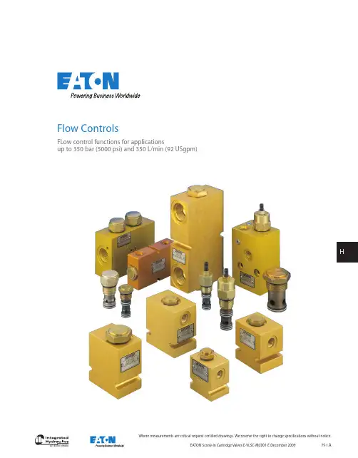
HWhere measurements are critical request certified drawings. We reserve the right to change specifications without notice.Flow ControlsFLow control functions for applicationsup to 350 bar (5000 psi) and 350 L/min (92 USgpm)Where measurements are critical request certified drawings. We reserve the right to change specifications without notice.Functional SymbolFlow ControlsValve locatorFlow Typical Model Cavity Rating PressurePageFlow regulator valve, fixedL/min (USgpm) bar (psi)FR5-8 C-8-2 10 (25) 280 (4000) H-100FR5-10 C-10-2 23 (6) 280 (4000) H-110FR1-16 C-16-2 114 (30) 210 (3000) H-120FR1-20C-20-2227 (60)210 (3000)H-130Flow Typical ModelCavityRatingPressurePageFlow regulator valve, adjustableL/min (USgpm) bar (psi)FR2-10 C-10-2 38 (10) 210 (3000) H-140FR2-16C-16-2114 (30)210 (3000)H-150Flow Typical ModelCavityRatingPressurePageFlow regulator with check L/min (USgpm) bar (psi)2CFRC60 A7447 4-60 (1-16) 350 (5000) H-160FAR1-10 C-10-2 1-38 (0.25-10) 310 (4500) H-170FAR1-12 C-12-2(u) 1.5-95 (0.4-25) 310 (4500) H-180FAR1-16C-16-23.8-114 (1-30)310 (4500)H-190Flow Typical ModelCavityRatingPressurePagePriority flow regulator, bypass, fixedL/min (USgpm) bar (psi)PFR5-8 C-8-3 <10 (2.5) 280 (4000) H-200PFR5-10 C-10-3 <23 (6) 280 (4000) H-210PFR15-10 C-10-3 <38 (10) 350 (5000) H-220PFR11-12 C-12-3 <30 (8) 350 (5000) H-230PFR11-16C-16-3<114 (30)350 (5000)H -240Flow Typical ModelCavityRatingPressurePagePriority flow regulator, bypass, adjustableL/min (USgpm) bar (psi)2CFP60CVA-27-04-0 <60 (16) 350 (5000) H-250PFR12-0 C-10-3 <64 (17) 350 5000) H-254PFR12-12 C-12-3 <45 (12) 350 (5000) H-260PFR2-16 C-16-3 <114 (30) 210 (3000) H -270PFR12-16C-16-3<114 (30)350 (5000) H -280Flow Typical ModelCavityRatingPressurePagePriority flow regulator L/min (USgpm) bar (psi)PFRD/S-12 C-12-5S 76 (20) 280 (4000) H-290PFRD/S-16 C-16-5S 150 (40) 280 (4000) H-300PFRD/S-20 C-20-5S 230 (60) 240 (3500) H-3102121313HWhere measurements are critical request certified drawings. We reserve the right to change specifications without notice.Functional SymbolFlow Controls (cont.)Valve locatorFlow Typical Model Cavity Rating PressurePageManual rotary flow restrictorL/min (USgpm) bar (psi)MRV2-10 C-10-2 <56 (15) 210 (3000) H-320MRV2-16C-16-2<170.3 (45)210 (3000) H-330Flow ModelCavityRatingPressure PageNeedle valve L/min (USgpm) bar (psi)2CR80A7447 <80 (20) 350 (5000) H-340Flow Typical ModelCavity Rating PressurePageNeedle valveL/min (USgpm) bar (psi)NV1-8 C-8-2 <45 (12) 280 (4000) H-342NV1-10 C-10-2 <45 (12) 210 (3000) H-350FCV7-10 C-10-2 <45 (12) 210 (3000) H-380FCV11-12 C-12-2(u) <114 (30) 350 (5000) H -390FCV6-16C-16-2<208 (55)210 (3000) H -400Flow Typical ModelCavityRatingPressurePageNeedle valve L/min (USgpm) bar (psi)NV1-16 C-16-2 <151 (40) 210 (3000) H -360NV1-20C-20-2 <265 (70) 210 (3000) H -370Flow Typical ModelCavityRatingPressurePagePressure compensator, restrictive L/min (USgpm) bar (psi)PCS3-10 C-10-3 <38 (10) 210 (3000) H-410PCS13-10 C-10-3 <38 (10) 350 (5000) H-420PCS3-12 C-12-3 <58 (15) 240 (3500) H-430PCS13-12 C-12-3 <58 (15) 350 (5000) H-440PCS3-16 C-16-3 <114 (30) 210 (3000) H -450PCS13-16 C-16-3 <114 (30) 350 (5000) H -460PCS3-20C-20-3<189 (50)210 (3000)H -470Flow Typical ModelCavityRatingPressurePagePressure compensator bypass/priority L/min (USgpm) bar (psi)PCS4-10C-10-4 <38 (10) 210 (3000) H-480PCS14-10 C-10-4 <38 (10) 350 (5000) H-490PCS4-12 C-12-4 <58 (15) 240 (3500) H-500PCS14-12 C-12-4 <58 (15) 350 (5000) H-510PCS4-16 C-16-4 <114 (30) 210 (3000) H -520PCS14-16 C-16-4 <114 (30) 350 (5000) H -530PCS4-20 C-20-4 <189 (50) 210 (3000) H -540122232Where measurements are critical request certified drawings. We reserve the right to change specifications without notice.Functional SymbolFlow Controls (cont.)Valve locatorFlow Typical Model Cavity Rating PressurePageFlow regulator/diverter L/min (USgpm) bar (psi)2FPH55 <55 (14) 280 (4000) H-5502FPH95 <95 (25) 350 (5000) H-5502FPH195<160 (42) 350 (5000) H -550Flow Typical ModelCavity Rating PressurePageFlow regulator/diverter L/min (USgpm) bar (psi)2FPH250 <200 (52) 350 (5000) H -5602FPH350<350 (92) 350 (5000) H -560Flow Typical Model Cavity Rating PressurePageFlow fuse L/min (USgpm) bar (psi)VF1-10 C-10-2 23 (6) 210 (3000) H-570VF11-1O C-10-2 23 (6) 350 (5000) H-570VF1-16 C-16-2 114 (30) 210 (3000) H-580Flow Typical Model Cavity Rating PressurePageFlow divider/conbiner L/min (USgpm) bar (psi)FDC1-16 C-16-4 <178 (47) 210 (3000) H -590FDC11-16 C-16-4 <140 (37) 350 (5000) H -6002CFD50 A12744 <40 (10.5) 350 (5000) H -6102CFD200CVB-42-04-0<220 (58)280 (4000)H -620Flow Typical ModelCavityRatingPressurePageFlow divider/combiner L/min (USgpm) bar (psi)FDC1-20Inline <141 (37) 210 (3000) H -630Flow Typical Model Cavity Rating PressurePageFlow divider/combiner, posi-traction L/min (USgpm) bar (psi)FDC3-16 C-16-4 <152 (40) 210 (3000) H -640Flow Typical ModelCavityRatingPressurePageFlow divider/combiner, posi-traction L/min (USgpm) bar (psi)FDC3-20 Inline <570 (150) 210 (3000) H-650Where measurements are critical request certified drawings. We reserve the right to change specifications without notice.This section gives basicspecifications for the complete line of Eaton's IntegratedHydraulics threaded cartridge flow control valves. Itspurpose is to provide a quick, convenient reference tool when choosing cartridge valves or designing a system using these components. Valve Features and Benefits Eaton offers a complete range of Integrated Hydraulics flow controls cartridge valves, with a variety of features, including:• P roducts in this catalog have been Fatigue tested to one million cycles at 132% or 10 million cycles at 115% of rated pressure.• N on-adjustable, pressure compensated, flow regulator for flows to 227 L/min (60 USgpm).• A djustable, pressurecompensated, flow regulator for flows to 114 L/min (30 USgpm).• F ixed and adjustable priority bypass type flow regulator for regulated flows to 114 L/min (30 USgpm).• A djustable flow control without free reverse flow check with flows rated to 114 L/min (30 USgpm).• A djustable flow control with free reverse flow check with flows rated to 45 L/min (12 USgpm).• N eedle valves with flows rated to 265 L/min (70 USgpm).• V elocity fuses with flows rated to 227 L/min (60 USgpm).• F low divider/combiners (FDC1 and FDC11) with flows rated to 568 L/min (150 USgpm).• P osi-traction valves (FDC13) with flows rated to 567 L/min (150 USgpm)• O perating pressures to 350 bar (5000 psi).Here are some of the benefits of Eaton flow controls:• A ll operating parts arehardened steel, ground and honed for long life and low leakage.• D esigned for maximumflexibility and minimal space requirements.• A ll exposed cartridgesurfaces are zinc dichromate plated to resist corrosion. Steel housings are available for cartridges rated to 350 bar (5000 psi) application pressures.• A ll aluminum manifolds are gold anodized to resist corrosion.• R eliable, economical and compact.• L ow leakage.• V ariety of adjustment options.• A djustments designed not to go spring solid at “full in” position or to allow the adjustment to be removed when backed out.Notable are the two styles of flow divider/combiner:FDC1/FDC11The FDC*1 is a cartridge type hydraulic flow divider-combiner valve. It divides and combines flow, regardless of systemload or pressure, proportionally per specified flow division.For example: FDC*1-10-*–66 will divide an incoming flow of 45 L/min (12 USgpm) equally out each port with an accuracy of 10% each side. With 45 L/min (12 USgpm) in at “3” port, flow out port “4” can be 22 L/min (6 USgpm) 4,5 L/min (1.2 USgpm) while flow at port “2” is 22,7 L/min (6 USgpm) 4,5 L/min (1.2 USgpm).The combining accuracy is the same with incoming flow at port “4” and “2” and flow out port “3” of 45 L/min (12 USgpm). Inlet flow at port “4” will be 22 L/min (6 USgpm) 4,5 L/min (1.2 USgpm). Inlet flow at port “2” will be 22 L/min (6 USgpm) 4,5 L/min (1.2 USgpm).Flow division or combining will be maintained even if unequal loads are placed on ports “4” and “2”.A special feature of the FDC*1–** is that it provides rephase flow to either port 2 or port 4 when one of the two is blocked. This feature is useful in hydraulic circuits that require cylinders to move at the same time. If one cylinder bottoms out first, the opposite cylinder is provided with “rephase” flow to allow the cylinder to bottom and start the cylinders together for movement in the opposite direction.FDC3/FDC13The FDC*3 is a cartridge type positive traction valve that divides and combines flow, regardless of system load or pressure, proportionally per specified flow division.This valve is used in place of a standard flow divider-combiner in systems where hydraulic motors are used as drive wheels on each side of the machine. The positive traction valve acts much like a standard flow divider-combiner as the vehicle travels in a straight line. Equal amounts of flow go to each “C” port. As the vehicle turns a corner, a standard flow divider will maintain equal flow to each drive motor. On a turn, it is necessary for the outer wheel to turn faster than the inner wheel. A standard flow divider-combiner will provide equal flow to each motor causing the drive motors to skid. The positive traction valve solves this problem by allowing the one motor to turn faster than the other.This operates in a similar way as a mechanical differential on an automobile. In a turn, the inside drive motor is restricted and builds up pressure, while the outside drive motor is without restriction. Under conditions of high differential pressure, the positive traction valve passes extra flow to the least restricted motor to prevent skidding. Under straight running conditions the differential pressure is low and equal amounts of flow are provided to each drive motor.Flow ControlsSection OverviewWARNINGFor pressure over 210 bar (3000 psi)use steel housing.Where measurements are critical request certified drawings. We reserve the right to change specifications without notice.AdjustmentsSetting must ALWAYS be carried out using an appropriate gauge and it must NOT be assumed that screwing anadjuster to its maximum or minimum position will yield the maximum or minimum stated design setting for that valve.‘R’ - HANDKNOB‘L’ - LEVER LINEAR ADJUSTMENT THROUGH 180° . VARIABLE TO GIVE1 TO 95 LITRES/MIN WITH THE ABILITY TO SET A MAXIMUMBETWEEN THESE FLOWSAvailable onlyon:2FP952FB952FR952FRC952FBAR95133.5 MAX75.0 M A X109‘D’ - DETENT11 POSITIVE POSITIONS 320° ROTATIONAvailable onlyon:2FP952FB952FR952FRC952FBAR95ø60.0049.00 M A X‘P’ - LEAKPROOF SCREWSetting must ALWAYS be carried out using an appropriate gauge and it must NOT be assumed that screwing an adjuster to its maximum or minimum position will yield the maximum or minimum stated design setting for that valve.‘R’ - HANDKNOB ‘L’ - LEVER LINEAR ADJUSTMENT THROUGH 180° . VARIABLE TO GIVE 1 TO 95 LITRES/MIN WITH THE ABILITY TO SET A MAXIMUM BETWEEN THESE FLOWS Available only on:2FP952FB952FR952FRC952FBAR95133.5 MAX 75.0 M A X109‘D’ - DETENT 11 POSITIVE POSITIONS 320° ROTATION Available only on:2FP952FB952FR952FRC952FBAR95ø60.0049.00 M A XAlternative Adjusters。
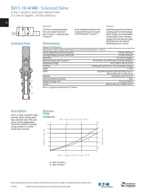
EATON Screw-In Cartridge Valves E-VLSC-MC001-E December 2009A-710.AWhere measurements are critical request certified drawings. We reserve the right to change specifications without notice.OperationIn the de-energized position this valve allows flow from port 4 to port 1 and from port 3 to port 2.In the energized position flow is allowed from port 3 to port 4 and from port 2 to port 1.FeaturesHardened, ground and honed working parts to limit leakage. IP69K Tough coil compatibility. Continuously rated. Compact design with low pressure drop. Rated pressure on all ports. Working pressure 350 bar.Pressure DropCartridge onlyPerformanceSectional View DescriptionThis is a 4-way 2-position, highpressure, direct acting, spool type solenoid valve. This valvecan be used in applications where the motion of a double acting cylinder or a motor needs to be reversed.A - Port 3 to port 2B - Port 4 to port 11501251007550250P r e s s u r e D r o p - p s i97531P r e s s u r e D r o p - b a r AB231580Fl ow - L/m i n (21,8 cSt oi l @ 49°C)246Fl ow - U Sgpm (105 SU S oi l @ 120°F)1EATON Screw-In Cartridge Valves E-VLSC-MC001-E December 2009A-711.AWhere measurements are critical request certified drawings. We reserve the right to change specifications without notice.Model Code1234910SV1110(V)45(M)8*****H 110010 Coil SeriesH - 10 series, 29WFor c oil p art n umbers a nd d imensions see section C.11 Special Features00 - None(Only required if valve has special features omitted if "00".)1 FunctionSV11 - Solenoid valve2 Size10 - 10 size3 Seal MaterialBlank - Buna-N V - Viton ®4 Style4 - 4-way, 2-position5 Manual Override OptionBlank - No manual override M - Manual override For v alve d imensions w ith m anual o ver-ride o ption i nstalled s ee p age A -980.6 Valve Housing MaterialBlank - Omit for cartridge only S - Steel 8 Voltage Rating00 - No coil12D - 12VDC 24D - 24VDC 36D - 36VDC 24A - 24VAC 115A - 115VAC 230A - 230VAC12B - 12VDC/w diode*24B - 24VDC/w diode**Optional arc suppression diode.9Coil TypesBlank - No coilG - ISO 4400 DIN 43650Q - Spade terminals W - Flying leadN - Deutsch (DC only)Y - Amp JR (DC only)D -M etripack 150 male (DC only)J - M etripack 280 male(DC only)For c oil p art n umbers a nd d imensions see section C.7 Port SizeCodePort SizeHousing Number0 Cartridge only 2G 1/4" BSPP 02-175139 3G 3/8" BSPP 02-175140 6T SAE 6 02-1751378TSAE 802-175138See section J for housing details.7**6(S)Dimensions mm (inch)Torque cartridge in steelhousing 68-75 Nm (50-55 ft lbs)Note: When solenoid valve is ordered as cartridge only, coil nut is included.Installation DrawingCartridge OnlyWARNINGMaintain 5-8 Nm (4-6 ft lbs)maximum torque on valve tube nut. Over tightening may cause valve failure.–––––。
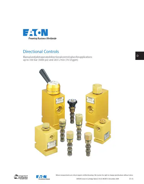
EATON Screw-In Cartridge Valves E-VLSC-MC001-E December 2009 D-1.AAn Eaton BrandWhere measurements are critical request certified drawings. We reserve the right to change specifications without notice.Directional ControlsManual a nd p ilot o perated d irectional c ontrol v alves f or a pplicationsup to 350 bar (5000 psi) and 265 L/min (70 USgpm)EATON Screw-In Cartridge Valves E-VLSC-MC001-E December 2009D-2.A An Eaton BrandWhere measurements are critical request certified drawings. We reserve the right to change specifications without notice.Functional SymbolFlow Typical Model Cavity Rating PressurePageManual rotary valveL/min (USgpm) bar (psi)MRV3-10 C-10-3 23 (6) 210 (3000) D-100MRV13-10 C-10-3 23 (6) 350 (5000) D-110MRV13-12 C-12-3 46 (12) 350 (5000) D-120MRV3-16 C-16-3 64 (17) 210 (3000) D-130MRV13-16C-16-364 (17)350 (5000)D-140Flow Typical ModelCavityRatingPressurePageManual rotary valveL/min (USgpm) bar (psi)MRV4-10 C-10-4 11 (3) 210 (3000) D-150MRV14-10 C-10-4 11 (3) 350 (5000) D-160MRV14-12 C-12-4 23 (6) 350 (5000) D-170MRV4-16 C-16-4 45 (12) 210 (3000) D-180MRV14-16C-16-445 (12)350 (5000)D-190Flow Typical ModelCavityRatingPressurePageManual rotary valveL/min (USgpm) bar (psi)MRV5-10 C-10-4 11 (3) 210 (3000) D-200MRV15-10 C-10-4 11 (3) 350 (5000) D-210MRV15-12 C-12-4 23 (6) 350 (5000) D-220MRV5-16 C-16-4 45 (12) 210 (3000) D-230MRV15-16C-16-445 (12)350 (5000)D-240Flow Typical ModelCavityRatingPressurePageManual rotary valveL/min (USgpm) bar (psi)MRV6-10 C-10-4 11 (3) 210 (3000) D-250MRV6-16 C-16-4 11 (3) 300 (5000) D-256Flow Typical Model Cavity Rating PressurePageManual lever valve, spoolL/min (USgpm) bar (psi)MLV9-12-A C-12-460 (13.9)210 (3000)D-292Flow Typical ModelCavityRatingPressurePageManual lever valve, spoolL/min (USgpm) bar (psi)MLV9-12-BC-12-460 (15.9)210 (3000)D-293Flow Typical ModelCavityRatingPressurePageManual lever valve, spoolL/min (USgpm) bar (psi)MLV9-12-EC-12-460 (15.9)210 (3000)D-294Flow Typical ModelCavityRatingPressurePageManual lever valve, spoolL/min (USgpm) bar (psi)MLV9-12-F C-12-4 60 (15.9) 210 (3000) D-295EATON Screw-In Cartridge Valves E-VLSC-MC001-E December 2009 D-3.AAn Eaton BrandDWhere measurements are critical request certified drawings. We reserve the right to change specifications without notice.Functional SymbolFlow Typical Model Cavity Rating PressurePageCheck MO L/min (USgpm) bar (psi)3CP2A8795.5-15 (1.4-4)210 (3000)D-320Flow Typical ModelCavityRatingPressurePageManual pull valve, NC L/min (USgpm) bar (psi)MPV1-10 C-10-2 45 (12) 210 (3000) D-330MPV3-10C-10-245 (12)210 (3000)D-340Flow Typical ModelCavityRatingPressurePageManual push valve L/min (USgpm) bar (psi)MSV1-12 C-12-3 41.8 (11) 210 (3000) D-350MSV11-10 C-10-3 23 (6) 350 (5000) D-360MSV11-12 C-12-3 30 (8) 350 (5000) D-370MSV12-12C-12-338 (10)350 (5000)D-390Flow Typical ModelCavityRatingPressurePageManual push valve L/min (USgpm) bar (psi)MSV2-12C-12-338 (10)210 (3000)D-380Flow Typical ModelCavityRatingPressurePageManual push valve L/min (USgpm) bar (psi)MSV5-12 C-12-3 41.8 (11) 210 (3000) D-400MSV15-12C-12-341.8 (11)350 (5000)D-410Flow Typical ModelCavityRatingPressurePageManual push valve L/min (USgpm) bar (psi)MSV3-12 C-12-4 53.2 (14) 210 (3000) D-420MSV13-12C-12-4 53.2 (14) 350 (5000) D-430Flow Typical ModelCavity Rating PressurePageManual push valve L/min (USgpm) bar (psi)MSV4-12 C-12-4 53.2 (14) 210 (3000) D-440MSV14-12C-12-453.2 (14)350 (5000)D-450Flow Typical ModelCavityRatingPressurePageManual push valve L/min (USgpm) bar (psi)MSV6-12 C-12-4 53.2 (14) 210 (3000) D-460MSV16-12C-12-453.2 (14)350 (5000)D-470Flow Typical ModelCavityRatingPressurePageManual push valve L/min (USgpm) bar (psi)MSV17-10 C-12-4 20 (5.3) 350 (5000) D-480MSV7-12 C-12-4 45 (11.9) 210 (3000) D-490MSV17-12 C-12-4 20 (5) 350 (5000) D-5002EATON Screw-In Cartridge Valves E-VLSC-MC001-E December 2009D-4.A An Eaton BrandWhere measurements are critical request certified drawings. We reserve the right to change specifications without notice.Functional SymbolFlow Typical Model Cavity Rating PressurePagePilot to shift 2/2 valve L/min (USgpm) bar (psi)PTS7-10 C-10-3 30 (8) 210 (3000) D-510PTS17-10 C-10-3 30 (8) 350 (5000) D-520PTS17-12C-12-3114 (30)350 (5000)D-530Flow Typical ModelCavityRatingPressurePagePilot to shift 2/2 valve L/min (USgpm) bar (psi)1RDS702 A21145 80 (20) 420 (6090) D-560Flow Typical ModelCavityRatingPressurePageBrake sequence L/min (USgpm) bar (psi)1SB10 A893 10 (2.5) 350 (5000) D-540Flow Typical Model Cavity Rating PressurePageBrake release shuttle L/min (USgpm) bar (psi)1SB304 A5302 30 (8) 350 (5000) D-550Flow Typical Model Cavity Rating PressurePagePilot to shift valve L/min (USgpm) bar (psi)PTS1-10 C-10-4 30 (8) 210 (3000) D-570PTS11-12 C-12-4 76 (20) 350 (5000) D-580PTS11-10 C-10-4 30 (8) 350 (5000) D-590PTS1-16 C-16-4 132 (35) 210 (3000) D-600PTS11-16 C-16-4 132 (35) 350 (5000) D-610PTS1-20 C-20-4265 (70)210 (3000)D-620Flow Typical ModelCavityRatingPressurePagePilot to shift valve L/min (USgpm) bar (psi)PTS12-10 C-10-4 30 (8) 350 (5000) D-630PTS12-12 C-12-4 114 (30) 350 (5000) D-640PTS2-16 C-16-4 132 (35) 210 (3000) D-650PTS12-16 C-16-4 132 (35) 350 (5000) D-660PTS2-20 C-20-4 265 (70) 210 (3000) D-670EATON Screw-In Cartridge Valves E-VLSC-MC001-E December 2009 D-5.AAn Eaton BrandDWhere measurements are critical request certified drawings. We reserve the right to change specifications without notice.Functional SymbolFlow Typical Model Cavity Rating PressurePagePilot to shift valve L/min (USgpm) bar (psi)PTS13-10 C-10-4 30 (8) 350 (5000) D-680PTS13-12 C-12-4 113 (30) 350 (5000) D-690PTS3-16 C-16-4 132 (35) 210 (3000) D-700PTS13-16 C-16-4 132 (35) 350 (5000) D-710PTS3-20 C-20-4 265 (70) 210 (3000) D-720PTS6-16 C-16-4 132 (35) 210 (3000) D-790PTS16-16C-16-4132 (35)350 (5000)D-800Flow Typical ModelCavityRatingPressurePagePilot to shift valve L/min (USgpm) bar (psi)PTS14-12 C-12-4 114 (30) 350 (5000) D-730PTS14-16 C-16-4 132 (35) 350 (5000) D-740PTS5-16 C-16-4 132 (35) 210 (3000) D-770PTS15-16 C-16-4 132 (35) 350 (5000) D-780Flow Typical ModelCavity Rating PressurePagePilot to shift valve L/min (USgpm) bar (psi)PTS5-10 C-10-3 11 (3) 210 (3000) D-750PTS5-12C-12-3 105 (28) 350 (5000) D-760Flow Typical ModelCavity Rating PressurePagePilot to shift valve L/min (USgpm) bar (psi)PTS9-8 C-8-5S 19 (5) 280 (4000) D-810PTS9-10 C-10-5S 38 (10) 280 (4000) D-820PTS9-12 C-12-5S 76 (20) 280 (4000) D-830PTS9-16 C-16-5S 151 (40) 280 (4000) D-840PTS9-20C-20-5S 230 (60) 280 (4000) D-850Flow Typical Model Cavity Rating PressurePageHot oil shuttle L/min (USgpm) bar (psi)1HSH20 CVB-22-06-0 20 (5) 350 (5000) D-856EATON Screw-In Cartridge Valves E-VLSC-MC001-E December 2009D-6.A An Eaton BrandWhere measurements are critical request certified drawings. We reserve the right to change specifications without notice.This section gives the basic specifications for the complete line of Eaton's Integrated Hydraulics threaded cartridge non-solenoid directional control valves. Its purpose is to provide a quick, convenient reference tool when choosing Vickers cartridge valves or designing a system using these components.Two pressure ratings areshown for all products featured in this catalog – typical application pressure and fatigue pressure. The typical application pressure rating is the maximum recommended operating pressure for the valve in a given system. The fatigue pressure rating is the pressure for the valve to be free for infinite life from metal fatigue.Features and Benefits • P roducts in this catalog have been fatigue tested for one million cycles at 132% or 10 million cycles at 115% of rated pressure.• A ll operating parts arehardened steel, ground and honed for long life and low leakage.• D esigned for maximumflexibility and minimal space requirements.• A ll exposed cartridgesurfaces are zinc dichromate plated to resist corrosion.• A ll aluminum manifolds are gold anodized to resist corrosion.• D esired settings may be locked down.• A luminum knob and cap options are available on some models.• R eliable, economicaland compact.WARNINGFor pressure over 210 bar (3000 psi)use steel housing.Directional ControlsIntroductionFunctional SymbolFlow Typical Model Cavity Rating PressurePageSequence L/min (USgpm) bar (psi)DSV4-10 C-10-4 26 (6.9) 350 (5000) D-860DSV4-12C-12-4 113 (29.9) 350 (5000) D -866Flow Typical ModelCavityRatingPressurePageHot oil shuttle L/min (USgpm) bar (psi)1HSH701 A21145 80 (21) 420 (6000) D-870Flow Typical ModelCavity Rating PressurePagePilot to shift valve L/min (USgpm) bar (psi)PTS6-10 C-10-4 23 (6) 210 (3000) D-880PTS16-10 C-10-4 23 (6) 350 (5000) D-890PTS16-12C-12-4 76 (20) 350 (5000) D-900EATON Screw-In Cartridge Valves E-VLSC-MC001-E December 2009 D-7.AAn Eaton BrandDWhere measurements are critical request certified drawings. We reserve the right to change specifications without notice.90º90º50.8(2.00)50.8(2.00)88.95(3.502)65.9(2.595)50.69(1.996)67.82(2.670)22.23(0.875)Dowel Pin D2 and E2 Adjustment.20 in Mating Housing#29 (0.136 + 0.002) - 0.00045º90º321“D” Style367.82(2.670)50.64(1.994)46.21(1.819)90º50.8(2.00)(288.95(3.502)65.9(2.595)50.69(1.996)22.23(0.875)Dowel PinD2 and E2 Adjustment.20 in Mating Housing#29 (0.136+ 0.002) - 0.00045º90º321“D” Style 367.82(2.670)50.64(1.994)46.21(1.819)21“E2” StyleAlternative Adjusters For Light Duty Aluminum Housings Only 9,41,0(1.61)PortPort 1 to 258,0(2.28)Locating41,0(1.61)17,1 ±? 0.05(0.672 ± 0.002)Ø 3,45/3,50(#29 or 0.136)drill x 4,8(0.187) deepin mating housingThis hole omitted from detent plate of MRV3-10(V)-D2/E2Locating pin hole,four optional slots in detent plate RV3-*MRV3-*Locating Pin InstallationMRV3-**(V)-D(2)26,95 (1.061)(1.0.50) h ex25" -12 Th d.(0.43)11,0 (0.438)58,0(2.28)Port 3 to 1Port 1 to 2105 (4.13)Locating pin76,0(3.0)45°45°Mid position (not for 2-position models)7(25(224,9 ± 0.05(0.98 ± 0.002)Locating pin hole,four optional slots in detent plateØ 3,45 3,50(#29 or 0.136)drill x 4,8(0.187) deepin mating housingInstallation9,5 (0.37)41,0(1.61)Port 3 to 1Port 1 to 283,0(3.27)58,0(2.28)Locating pin45°45°M p (n 2m41,0(1.61)38,1(1.50)Ø 25,4 (1.0)42,0(1.65)50136)eephousingng pin hole,ptional slots ent plateMRV3-**(V)-D(2)MRV3-**(V)-E(2)ng Pin ation9,5 (0.37)(1.61)Port 1 to 283,0(3.27)58,0(2.28)Locating pin 45°Mid position (not for 2-position models)41,0(1.61)38,1(1.50)Ø 25,4 (1.0)42,0(1.65)17,1 ±? 0.05(0.672 ± 0.002)Ø 3,45/3,50(#29 or 0.136)drill x 4,8(0.187) deepin mating housingThis hole omitted from detent plate of MRV3-10(V)-D2/E2Locating pin hole,four optional slots in detent plateMRV3-**(V)-E(2)Locating PinInstallation D(2)Size 10Size 10E(2)Size 10Locating PIN Installation D(2)Size 12Size 12E(2)Size 12Locating PIN InstallationD(2)Size 16Size 16Locating PIN Installation 90º90º50.8(2.00)50.8(2.00)88.95(3.502)65.9(2.595)50.69(1.996)67.82(2.670)22.23(0.875)Dowel PinD2 and E2 Adjustment.20 in Mating Housing #29 (0.136 + 0.002) -0.00045º90º。
克泰螺纹插装阀样本的全面评估与价值探索导言在工业领域,阀门作为管道系统中的重要组成部分,不仅能控制流体的流动,还能保证系统的稳定运行。
而克泰螺纹插装阀样本作为一种常见的阀门产品,在各个行业中广泛应用,并以其高质量和先进技术赢得了用户的赞誉。
本文将从深度和广度两个方面对克泰螺纹插装阀样本进行全面评估,并探讨其在工业应用中的实际价值。
一、克泰螺纹插装阀样本简介1.克泰螺纹插装阀样本定义和分类克泰螺纹插装阀样本是一种通过螺纹连接,插装于管道系统中的阀门。
根据使用场景和特征的不同,克泰螺纹插装阀样本可分为不锈钢螺纹插装阀样本、铜螺纹插装阀样本、铸铁螺纹插装阀样本等多种类型。
每种类型的阀门都有其独特的特点和适用领域。
2.克泰螺纹插装阀样本的结构和原理克泰螺纹插装阀样本由阀体、阀盖、阀瓣等组成。
其工作原理是通过旋转阀瓣实现对管道中流体的控制,当阀瓣旋转到开启位置时,流体得以通行,当阀瓣旋转到关闭位置时,流体被阻断。
二、克泰螺纹插装阀样本的深度评估1.技术参数和性能评估克泰螺纹插装阀样本具有较高的工作温度范围、耐腐蚀性和密封性能。
通过对其技术参数和性能指标的评估,可以了解其在不同工作条件下的适用性和可靠性。
2.安全性评估在工业领域,安全性是阀门产品最重要的考量因素之一。
通过评估克泰螺纹插装阀样本的材料选择、制造工艺和安全措施等方面,可以了解其在工业应用场景中的安全性能并提供合理的安全保障。
3.实际应用评估通过调查和了解克泰螺纹插装阀样本在实际工业应用中的使用情况和用户反馈,可以评估其在不同行业的适用性和优劣势,并为用户选择合适的阀门产品提供参考依据。
三、克泰螺纹插装阀样本的广度评估1.行业应用领域评估克泰螺纹插装阀样本广泛应用于化工、石油、电力、冶金等行业领域,通过对每个行业的特点和需求的评估,可以了解克泰螺纹插装阀样本在不同行业中的适用性和应用价值。
2.市场竞争力评估阀门市场竞争激烈,针对克泰螺纹插装阀样本,通过对竞争对手产品的比较和市场份额的评估,可以了解其在市场中的地位和竞争优势。
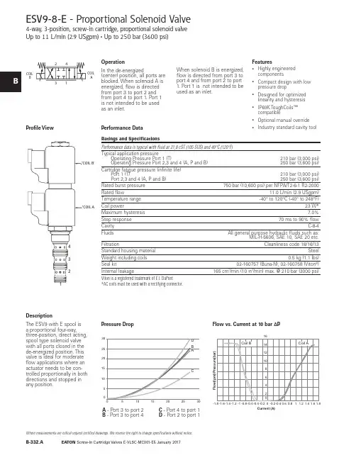
Screw-In Cartridge Valves E-VLSC-MC001-E5 January 2017B-332.A Where measurements are critical request certified drawings. We reserve the right to change specifications without notice.5510101515202025302530DB ACESV9-8-E - Proportional Solenoid Valve4-way, 3-position, screw-in cartridge, proportional solenoid valve Up to 11 L/min (2.9 USgpm) • Up to 250 bar (3600 psi)DescriptionThe ESV9 with E spool is a proportional four-way,three-position, direct acting,spool type solenoid valve with all ports closed in thede-energized position. This valve is ideal for moderate flow applications where an actuator needs to be con-trolled proportionally in both directions and stopped in any position.OperationIn the de-energized(center) position, all ports are blocked. When solenoid A is energized, flow is directed from port 3 to port 2 and from port 4 to port 1. Port 1 is not intended to be used as an inlet.When solenoid B is energized, flow is directed from port 3 to port 4 and from port 2 to port 1. Port 1 is not intended to be used as an inlet.Features• Highly engineered components• Compact design with low pressure drop• Designed for optimized linearity and hysteresis • IP69K ToughCoils™ compatible•Optional manual override •Industry standard cavity toolPerformance DataProfile View Pressure DropFlow vs. Current at 10 bar ∆PA - Port 3 to port 2B - Port 3 to port 4C - Port 4 to port 1D - Port 2 to port 1COIL B3124COIL ACurrent (A)5510101515202025302530D B ACScrew-In Cartridge Valves E-VLSC-MC001-E5 January 2017B-333.ABWhere measurements are critical request certified drawings. We reserve the right to change specifications without notice.ports to decay to tank pres-sure in the de-energized condition.A - Port 3 or port 2 energizedB - Port 3 to port 4 energizedC - Port 2 or port 1 energizedD - Port 2 to port 1 de-energizedCurrent (A)E - Port 4 to port 1 energizedF - Port 4 to port 1 de-energizedScrew-In Cartridge Valves E-VLSC-MC001-E5 January 2017B-334.A Where measurements are critical request certified drawings. We reserve the right to change specifications without notice.Model Code1ESV93*4*5*–––––1 FunctionESV9 - Proportional solenoid valve2 Size8 - 8 size3 Seal MaterialBlank - Buna-N V - Viton®28CodePort SizeHousing NumberAlumi ni um Steel0 Cartridge only A2G 1/4” BSPP 02-160747A3G 3/8” BSPP 02-160748A6H SAE 6 02-160749A8H SAE 8 02-160750S2G 1/4” BSPP 02-160753S3G 3/8” BSPP 02-160754S6T SAE 6 02-160751S8TSAE 802-160752See section J for housing details.6 Housing Material and PortsWARNINGAluminum housingscan be used for pres-sures up to 210 bar (3000 psi). Steel housings must be used for operating pressures above210 bar (3000 psi).EF4 Spool Center ConditionCOIL B3124COIL A24COIL BCOIL A6***5 Manual Override Option0 - No manual overrideM - Manual override, push pull typeFor valve dimensions with manual override, see pages B873.7 Coil Voltage and T ype000 - No coil012D - 12V DC without diode 024D - 24V DC without diode 012B - 12V DC with diode 024B - 24V DC with diode8 Connection T ypeBlank - No coilN - Deutsch male, DT04-2P , integrated G - DIN 43650 W - Flying leadY - Amp Jr (DC Only) Mating Connector: AMP 963040-3 or equivalentD0 - MetriPackR 150 Male, Integrated (DC Only) Mating Connector: Delphi 12052641See Section C for coil details .1 T hese model digits are not stamped onthe valve.10 Coil Special Feature00 - None11 Valve Special Features 100 - None(Only required if valve has special features omitted if "00".)12 Design CodeA - Design code 009 Coil SeriesBlank - No coil P - P SeriesToughCoils™ 23 W11**12A10**8*9*7****Screw-In Cartridge Valves E-VLSC-MC001-E5 January 2017B-335.AWhere measurements are critical request certified drawings. We reserve the right to change specifications without notice.Dimensions mm (inch)Torque cartridge in aluminum housing 34-41 Nm (25.0 - 30.0 ft. lbs.) and 34-41 Nm (25.0 - 30.0 ft. lbs. ) in a steel housingWhen solenoid valve isordered without coils, it will be supplied with coil spacer and coil nut.Spare PartsCoil Nut for MO 565559Coil Nut without MO 565558Coil Spacer02-186730WARNINGMaintain 5-8 Nm (4-6 ft lbs) maximumtorque on coil nut.Over tightening may causevalve failure.31.8[1.25]ESV9-8 without MOESV9-8 with MOScrew-In Cartridge Valves E-VLSC-MC001-E4 May 2016B-332.A Where measurements are critical request certified drawings. We reserve the right to change specifications without notice.Flow - lpm P r e s s u r e D r o p - p s i5ESV9-10-E - Proportional Solenoid Valve4-way, 3-position, screw-in cartridge, proportional solenoid valve Up to 22 L/min (5.8 USgpm) • Up to 250 bar (3600 psi)DescriptionThe ESV9 with E spool is a proportional four-way,three-position, direct acting, spool type solenoid valve with all ports closed in the de-energized position. This valve is ideal for moderate flow applications where an actuator needs to be con-trolled proportionally in both directions and stopped in any position.OperationIn the de-energized(center) position, all ports are blocked. When solenoid A is energized, flow is directed from port 3 to port 2 and from port 4 to port 1. Port 1 is not intended to be used as an inlet.When solenoid B is energized, flow is directed from port 3 to port 4 and from port 2 to port 1. Port 1 is not intended to be used as an inlet.Features•Highly engineered components•Compact design with low pressure drop•Designed for optimized linearity and hysteresis •IP69K Large ToughCoils™ compatible•Optional manual override •Industry standard cavity toolPerformance DataProfile ViewA - Port 3 to port 2B - Port 3 to port 4C - Port 4 to port 1D - Port 2 to port 1“Coil B”3421COIL B3124COIL A510152025Coil B Coil A2.00 1.501.000.500.000.50 1.00 1.502.00F l o w (l p m )Current (A)Screw-In Cartridge Valves E-VLSC-MC001-E4 May 2016B-333.AWhere measurements are critical request certified drawings. We reserve the right to change specifications without notice.ESV9-10-F - Proportional Solenoid Valve4-way, 3-position, screw-in cartridge, proportional solenoid valve Up to 22 L/min (5.8 USgpm) • Up to 250 bar (3600 psi)DescriptionThe ESV9 with F spool is a proportional four way, three position, direct acting, spool type solenoid valve. In the de-energized condition Port 2 and 4 are open to tank with the inlet port 3 blocked. This valve is ideal formoderate flow applications where an actuator needs to be moved in both directions and stopped in any position while allowing the service ports to decay to tank pres-sure in the de-energized condition.OperationIn the de-energized (cen-ter) position, port 1, port 2, and port 4 are open to each other while port 3 is blocked. When solenoid A is energized, flow isdirected from port 3 to port 2 and from port 4 to port 1. When solenoid B is energized, flow is directed from port 3 to port 4 and from port 2 to port 1.Features•Highly engineered components•Compact design with low pressure drop•Designed for optimized linearity and hysteresis •IP69K Large ToughCoils™ compatible•Optional manual override •Industry standard cavity tool .Performance DataProfile View Pressure DropA - Port 3 or port 2 energizedB - Port 3 to port 4 energizedC - Port 2 or port 1 energizedD - Port 2 to port 1 de-energizedFlow - Ipm 0510152025303540051015202530354045505560ABC E DFP r e s s u r e D r o p - b a r“Coil B”“Coil A”342124COIL BCOILA510152025Coil B Coil A2.00 1.501.000.500.000.501.001.502.00F l o w (l p m )Current (A)E - Port 4 to port 1 energizedF - Port 4 to port 1 de-energizedFlow vs. Current at 10 bar ∆PScrew-In Cartridge Valves E-VLSC-MC001-E4 May 2016B-334.A Where measurements are critical request certified drawings. We reserve the right to change specifications without notice.Up to 22 L/min (5.8 USgpm) • Up to 250 bar (3600 psi)Model Code1ESV93*4*5*–––––1 FunctionESV9 - Proportional solenoid valve2 S ize10 - 10 size3 S eal MaterialBlank - Buna-N V - Viton®210Code Port SizeHou s ing NumberAluminium Steel0 Cartridge only A2G 1/4” BSPP 02-185804A3G 3/8” BSPP 02-185805A6H SAE 6 02-185802A8H SAE 8 02-185803S2G 1/4” BSPP 02-175139S3G 3/8” BSPP 02-175140S6T SAE 6 02-175137S8TSAE 802-175138See section J for housing details.6 Housing Material and PortsWARNINGAluminum housingscan be used for pres-sures up to 210 bar (3000 psi). Steel housings must be used for operating pressures above210 bar (3000 psi).EF4 Spool Center ConditionCOIL B3124COIL A24COIL BCOILA6***5 Manual Override Option0 - No manual overrideM - Manual override, push pull typeFor valve dimensions with manual override, see pages B873.7 Coil Voltage and T ype000 - No coil012D - 12V DC without diode 024D - 24V DC without diode 012B - 12V DC with diode 024B - 24V DC with diode8 Connection T ypeBlank - No coilN - Deutsch male, DT04-2P , integrated G - DIN 43650 W - Flying leadY - Amp Jr (DC Only) Mating Connector: AMP 963040-3 or equivalentD0 - MetriPackR 150 Male, Integrated (DC Only) Mating Connector: Delphi 12052641See Section C for coil details .1 T hese model digits are not stamped onthe valve.10 Coil Special Feature00 - None11 Valve Special Features 100 - None(Only required if valve has special features omitted if "00".)12 Design CodeA - Design code 009 Coil S eriesBlank - No coil L - L Series Large ToughCoils™ 28 W11**12A10**8*9*7****Screw-In Cartridge Valves E-VLSC-MC001-E4 May 2016B-335.ABWhere measurements are critical request certified drawings. We reserve the right to change specifications without notice.Up to 22 L/min (5.8 USgpm) • 250 bar (3000 psi)Dimensions mm (inch)Torque cartridge in aluminum housing 47 - 54 Nm (34.7 - 39.8 ft. lbs.) and 56 - 62 Nm (41.3 - 45.7 ft. lbs. ) in a steel housingValve is shown with large tough coil.Note: The ESV9-10 is shipped with a spacer (6038409-001) to be used with the Large Tough Coil. Spacer is not needed when used with the EN490 coil.When solenoid valve isordered without coils, it will be supplied with coil spacer and coil nut.Spare PartsCoil Nut for MO 6038813-001Coil Nut without MO 02-148332Coil Spacer6038409-001WARNINGMaintain 5-8 Nm (4-6 ft lbs) maximumtorque on valve tube nut. Over tightening may cause valve failure.1。
一些国外螺纹插装阀生产商介绍一些国外螺纹插装阀生产商介绍张海平张海平 20120122-1212--191.HYDRAFORCE(1.HYDRAFORCE(海德福斯海德福斯海德福斯))公司公司1983年,当时世界上规模最大的螺纹插装阀专业生产厂Modular公司被Vickers公司并购。
两年后,3个当年Modular的员工建立了HYDRAFORCE公司。
至今,HF在美国的厂房达13,000m²,在英国的厂房也有4,650m²。
2003年销售额已达90MUS$,螺纹插装阀的生产规模又是世界第一。
以前产品基本以中压为主,无平衡阀。
现在也已开发了很多高压的阀。
孔型以ICC 系列为主。
2.SUN 公司公司SUN 升旭公司建立于1970年。
1997年上市。
目前,在美国的Florida、Kansas、英国、德国、法国、韩国、印度多处有子公司。
1998年与台湾橡达公司合作,在上海松江建立了一个合资子公司。
2011年年初宣布,退出了合资,建立了它自己在中国的销售办事处。
橡达公司仍然是SUN 产品的代理商。
2004年螺纹插装阀的产能就达到5.8万件/周。
SUN 公司很迅速地从金融危机中走出来。
2010年销售额达到了2006年的水平,约为150MUS$,税后纯利润达12%。
公司销售收入约75%来自螺纹插装阀,25%则来自阀块和集成块。
产品约70%供应移动液压,30%固定液压。
孔型自成一格,公制英制螺纹兼有。
3.Sterling Hydraulics 公司公司母公司在英国的Crewkerne。
以前生产汽车零件,60年代后期开始生产螺纹插装阀。
90年代初,美国Waterman公司的主任设计师Kolchinski先生到了Sterling公司美国分部,开始开发电磁阀。
95年形成全系列。
他设计的电磁线圈后被Parker公司称为Super-Coil超级线圈。
插装阀生产能力达到1.5百万件/年。
30%供应建筑机械公司Caterpillar。
螺纹插装阀介绍之二螺纹插装阀介绍之二 平衡阀平衡阀张海平张海平摘要摘要::本文概述了选用平衡阀时必须注意的特性,介绍了不同类型的制成螺纹插装形式的平衡阀,它们的性能和工作原理。
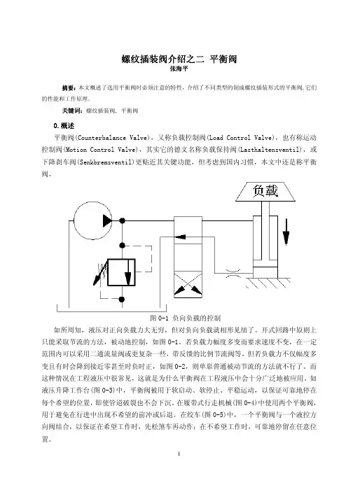
关键词关键词::螺纹插装阀, 平衡阀0.概述概述平衡阀(Counterbalance Valve),又称负载控制阀(Load Control Valve),也有称运动控制阀(Motion Control Valve),其实它的德文名称负载保持阀(Lasthaltensventil),或下降刹车阀(Senkbremsventil)更贴近其关键功能,但考虑到国内习惯,本文中还是称平衡阀。
图0-1 负向负载的控制如所周知,液压对正向负载力大无穷,但对负向负载就相形见绌了。
开式回路中原则上只能采取节流的方法,被动地控制,如图0-1。
若负载力幅度多变而要求速度不变,在一定范围内可以采用二通流量阀或更复杂一些,带反馈的比例节流阀等。
但若负载力不仅幅度多变且有时会降到接近零甚至时负时正,如图0-2,则单靠普通被动节流的方法就不行了。
而这种情况在工程液压中很常见,这就是为什么平衡阀在工程液压中会十分广泛地被应用。
如液压升降工作台(图0-3)中,平衡阀被用于软启动、软停止、平稳运动,以保证可靠地停在每个希望的位置,即使管道破裂也不会下沉。
在履带式行走机械(图0-4)中使用两个平衡阀,用于避免在行进中出现不希望的前冲或后退。
在绞车(图0-5)中,一个平衡阀与一个液控方向阀结合,以保证在希望工作时,先松煞车再动作;在不希望工作时,可靠地停留在任意位置。
因为平衡阀消耗能量甚多,容易引起过热,通常不用于低压系统(<5 MPa),也不用于闭环系统。
摆动负载图0-2摆动负载液压升降工作台 图0-4履带式行走机械履带式行走机械图0-3液压升降工作台绞车5 绞车图0-5绞车功能0.1功能平衡阀可以说是集三阀于一身,参见图0.1-1。
用平衡阀控制负向负载0.1--1用平衡阀控制负向负载图0.1一是作为单向阀(2→1)。
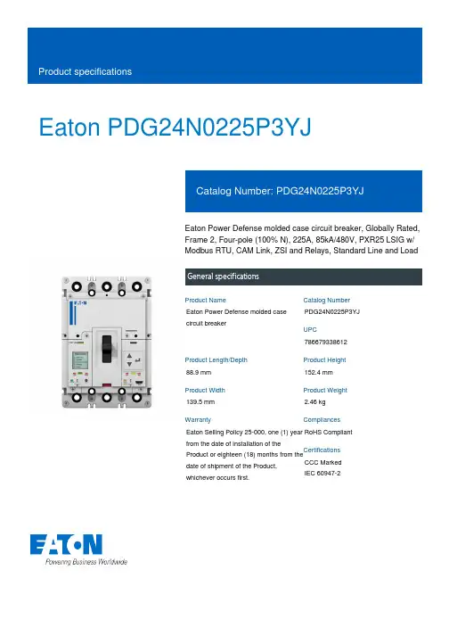
Eaton PDG24N0225P3YJEaton Power Defense molded case circuit breaker, Globally Rated, Frame 2, Four-pole (100% N), 225A, 85kA/480V, PXR25 LSIG w/ Modbus RTU, CAM Link, ZSI and Relays, Standard Line and LoadGeneral specificationsEaton Power Defense molded case circuit breakerPDG24N0225P3YJ 78667933861288.9 mm 152.4 mm 139.5 mm 2.46 kg Eaton Selling Policy 25-000, one (1) year from the date of installation of theProduct or eighteen (18) months from thedate of shipment of the Product,whichever occurs first.RoHS Compliant CCC MarkedIEC 60947-2Product NameCatalog Number UPCProduct Length/Depth Product Height Product Width Product Weight WarrantyCompliancesCertifications225 AComplete breaker 2Four-pole (100% N)PD2 GlobalClass APXR 25 LSIGModbus RTU and CAM Link600 Vac600 V100% neutral protectionStandard Line and Load85 kAIC at 480 Vac22 kAIC Icu @125 Vdc70 kAIC Icu/ 50 kAIC Ics/ 154 kAIC Icm @440V (IEC)70 kAIC Icu/ 70 kAIC Ics/ 154 kAIC Icm @380-415V (IEC) 10 kAIC Icu/ 5 kAIC Ics/ 21 kAIC Icm @690V (IEC)22 kAIC Icu @250 Vdc30/25 kAIC Icu/ 15/13 kAIC Ics @525V South Africa (IEC) 85 kAIC @480V (UL)150 kAIC Icu/ 100 kAIC Ics/ 330 kAIC Icm @240V (IEC)30/25 kAIC @600V (UL/CSA)150 kAIC @240V (UL)65 kAIC Icu/ 40 kAIC Ics/ 143 kAIC Icm @480V Brazil (IEC) 25 kAIC @600V (UL/CSA)Eaton Power Defense MCCB PDG24N0225P3YJ 3D drawingPower Xpert Protection Manager x64Power Xpert Protection Manager x32Consulting application guide - molded case circuit breakersPower Defense technical selling bookletPower Defense brochurePower Defense molded case circuit breaker selection poster Power Defense molded case circuit breakers - Frame 2 product aidMolded case circuit breakers catalogAmperage RatingCircuit breaker frame type FrameNumber of poles Circuit breaker type ClassTrip Type CommunicationVoltage ratingVoltage rating - maxProtectionTerminalsInterrupt rating Interrupt rating range 3D CAD drawing package Application notesBrochuresCatalogsPower Xpert Release trip units for Power Defense molded case circuit breakersCertification reportsPDG4 CCC certificationPDG4 CB reportPDG2 CB reportEU Declaration of Conformity - Power Defense molded case circuit breakersInstallation instructionsPower Defense Frame 2 clamp terminal (steel), 20A, 4 pole instructions - IL012246EN H04Power Defense Frame 2 box terminal (aluminum), 225A, 4 pole instructions - IL012235EN H04Power Defense Frame 2 screw terminal_end cap kit, 225A, 3 pole instructions - IL012258EN H01Power Defense Frame 1 IEC and Frame 2 Rotary Mechanism with NFPA Handle Attachment Instructions (IL012260EN).pdfPower Defense Frame 2 tunnel terminal (aluminum), 50A, 4 pole instructions - IL012236EN H04Power Defense Frame 2 box terminal (steel), 100A, 4 pole instructions - IL012234EN H04Power Defense Frame 2 shunt trip UVR instructions - IL012130EN Power Defense Frame 2 global terminal shield, 4 pole - IL012330EN Power Defense Frame 2 terminal kit - PDG2X3(2)(4)TA150RF instructions - IL012244EN H01Power Defense Frame 2 terminal kit - PDG2X3(2)(4)TA225RF instructions - IL012245EN H01Power Defense Frame 2/3/4/5/6 voltage neutral sensor module wiring instructions – IL012316ENPower Defense Frame 2 multi wire connector kit -PDG2X3(2)(4)TA2253W instructions - IL012243EN H01Power Defense Frame 1-2-3-4 IP door barrier assembly instructions -IL012278ENPower Defense Frame 2 tunnel terminal (aluminum), 100A, 4 pole instructions - IL012237EN H04Power Defense Frame 2 locking devices and handle block instructions - IL012149ENPower Defense Frame 2 tunnel terminal kits - PDG2X1TA225K instructions- IL012239EN H01Power Defense Frame 2 tunnel terminal (aluminum), 150A, 4 pole instructions - IL012238EN H04Power Defense Frame 2 multi wire connector kit -PDG2X3(2)(4)TA2256W instructions - IL012242EN H01Power Defense Frame 2 PDG2 and PDC(E)9 breaker instructions -IL012106ENPower Defense Frame 2 Bell Alarm Switch Instructions (IL012154EN).pdf Power Defense Frame 2 bell alarm switch instructions - IL012154EN Installation videosPower Defense Frame 2 TMTU Aux, Alarm, ST and UVR Animated Instructions.rhPower Defense Frame 2 Bell Alarm with PXR Animated Instructions.pdf.rh Power Defense Frame 2 withTMTU, Shunt Trip_UVR Animated Instructions.rhMultimediaPower Defense Frame 3 Variable Depth Rotary Handle Mechanism Installation How-To VideoPower Defense Frame 2 Variable Depth Rotary Handle Mechanism Installation How-To VideoPower Defense Frame 2 Aux, Alarm, Shunt Trip, and UVR How-To Video Power Defense Frame 2 Direct Rotary Handle Mechanism Installation How-To VideoEaton Power Defense for superior arc flash safetyPower Defense Frame 5 Trip Unit How-To VideoPower Defense molded case circuit breakersPower Defense BreakersPower Defense Frame 6 Trip Unit How-To VideoSpecifications and datasheetsEaton Specification Sheet - PDG24N0225P3YJTime/current curvesPower Defense time current curve Frame 2 - PD2White papersMolded case and low-voltage power circuit breaker healthIntelligent circuit protection yields space savingsSingle and double break MCCB performance revisitedIntelligent power starts with accurate, actionable dataMaking a better machineSafer by design: arc energy reduction techniquesMolded case and low-voltage breaker healthEaton Corporation plc Eaton House30 Pembroke Road Dublin 4, Ireland © 2023 Eaton. All Rights Reserved. Eaton is a registered trademark.All other trademarks areproperty of their respectiveowners./socialmedia。
螺纹插装阀品牌见网友发过一个插装阀品牌的帖子,以我个人的理解,发一个常见螺纹插装阀品牌的帖子,也许有一些遗漏的好产品,好品牌,欢迎广大行业人士跟帖,探讨一下.此液压螺纹插装阀不包括二通插装阀.第一梯队插装阀:产销超过或者接近一亿美金的,质量跟销量的综合比较: Hydraforce:行业第一的销售业绩说明了该产品在中低压产品中的性价比很高,该阀仿照以前Modular产品来做的,但是平衡阀基本上没有做,现在发布的小流量平衡阀,高压阀也在陆续发布.Parker:旗下产品sterling,waterman,fluid power system的整合,机械阀跟电磁阀的强强组合,绝对是插装阀质量最好,产品最全的厂家之一Eaton:螺纹插装阀主要是Modular,IH的产品,产品很丰富,阀的全面程度与parker差不多.Sun hydraulics:位于世界第二销量的厂家,机械阀绝对是行业老大,但是电磁阀不是很全面,也可能是思路的问题,先导电磁阀加逻辑阀来实现大流量电磁阀.Comatrol (Sauer danfoss):收购整合了丹麦danfoss fluid control,全世界最早做插装阀的品牌之一,美国co mand control,意大利comatrol,具有很全面的插装阀产品,特点是比例流量控制及方向控制.现在comatrol品牌全球独立销售,估计未来会更好.Rexroth (Oil control):在欧洲,oil control最早是danfoss fluid control的代理商,慢慢开始生产插装阀,最后收购了tarp及edi后,实力得到了很大提高,被rexroth收购以后,前景应该更好.Bucher:收购瑞士的Hydrotechnik Frutigen AG,不包含CCC.Hydac:挖机先导,风电液压用量很大.第二梯队插装阀:以下品牌不做论述Delta power:Deltrol:Bucher(ccc):Walvoil(oleostar):Hydra control(nem):Argo hytos:主要以cetop标准阀为主,插装阀部分英国一厂家给贴牌.第三梯队插装阀:除上述品牌以外的各种意大利品牌:luen,atlantic,cbf,hbs等很多…第四梯队插装阀:武汉机械(Winner):克泰:海宏:。
Installation Instructions for Eaton Surge Protective Devices XXCFXXX30 and XXCFXXX60ContentsDescription Page1.0 Setup (2)1.1 Before Installation (2)1.2 Installation (2)1.3 Wiring (2)1.3.1 Series Wiring Applications (3)1.3.2 Parallel Wiring Applications (3)1.4 Apply Power (3)1.5 Specifications (3)1.6 Warranty (4)XXCF12030XXCF120602Instruction Manual IM01005025EEffective April 2014Installation Instructions forEaton SurgeEATON WARNINGHAZARDOUS VOLTAGES PRESENTIMPROPER INSTALLATION OR MISAPPLICATION OF THESE DEVICES MAY RESULT IN SERIOUS INJURY TO INSTALLER AND/OR DAMAGE TO ELECTRI-CAL SYSTEM OR RELATED EQUIPMENT. READ AND UNDERSTAND ALL INSTRUCTIONS BEFORE BEGINNING INSTALLATION. PROTECTIVE EYE-WEAR SHOULD BE WORN WHENEVER WORKING AROUND HAZARDOUS VOLTAGES.NOTICEALL INSTRUCTIONS AND MEASUREMENTS MUST BE COMPLETED BY A LICENSED/QUALIFIED ELECTRICIAN IN ACCORDANCE WITH THE U.S. NATIONAL ELECTRICAL CODE, STATE AND LOCAL CODES OR OTHER APPLI-CABLE COUNTRY CODES. THE U.S. NATIONAL ELECTRICAL CODE AND STATE AND LOCAL REQUIREMENTS (OR OTHER APPLICABLE COUNTRY CODES) SUPERSEDE THIS INSTRUCTION.Catalog NumberAmpsVoltage RangeMode VPR MCOV In SCCRPeak Surge Current PhaseXXCF1203033048 - 149 Vdc 1 100 -127 VacL-N5001505kA 10kA120kAL-G 500150N-G 500150XXCF1206036048 - 149 Vdc 1 100 -127 VacL-N5001505kA 10kA 120kA L-G 500150N-G500150Catalog NumberAmpsVoltage RangeMode MCOV In SCCRPeak Surge Current Phase XXCF24030230150 - 300 Vdc 1200 - 240 VacL-N, L-G, N-GN/A N/A N/A 80kAXXCF24060260150 - 300 Vdc 1200 - 240 VacL-N, L-G, N-GN/AN/AN/A80kA1 UL 1449 3rd Edition does not list SPD products rated less than 100 Vac or DC voltages.21283 4th Edition, EMI Filter 3UL 1449 3rd Edition, UL 1283 5th Edition1.0 SetupVerify system voltages do not exceed those listed in Section 1.5, Specifications.•All AC measurements should be completed with an RMS voltme-ter.• All DC measurements should be completed with a DC voltmeter. •DO NOT INSTALL FILTER IF MEASURED VOLTAGE EXCEEDS MAXIMUM OPERATING LIMITS.Choose location for filter installation so that maximum separation can be maintained between input leads, output leads and ground leads.1.1 Before InstallationREMOVE POWER FROM ELECTRICAL SYSTEM BEFORE MOUNTING FILTER.•Filter MUST be mounted within enclosure to assure personnel safety from exposed terminals.IMPORTANT:FILTER SHOULD BE LOCATED SO THAT THE SHORTEST POSSIBLE CONDUC-TOR LENGTH MAY BE USED.•Filter should be mounted to allow maximum separation between input and output wiring.•Filter contains no position-oriented components and can be mounted upside down or sideways.•Filter should be placed in electrical circuit so that it is the last device in the circuit before equipment to be protected.1.2 InstallationFILTER MUST BE CONNECTED TO ELECTRICAL SYSTEM WITH A CIRCUIT BREAKER:•1 - Single Pole / Single Throw 40A or 100A circuit breaker(s), The Interrupting Rating of the Circuit Breaker Shall Not Be Less Than the Available Fault Current. Circuit Breaker Ratings of 40A, 240V/415V, 10kA Min. AIC Rating for 30 amp devices and Circuit Breaker Ratings of 100A, 480V, 10kA Min. AIC Rating for 60 amp devices.Note: Pre-existing breaker(s) of the rated load size may be utilized if provisions for multi-conductor connections are made according to N.E.C. 110-14A.•If Neutral wire is to be utilized as L2/NEU, then circuit breaker should be provided for that phase.REMOVE POWER FROM ELECTRICAL SYSTEM BEFORE INSTALL -ING FILTER.Mechanically mount filter.•Mount filter using mounting flange holes or optional DIN bracket listed below.•Filter should be mounted to allow maximum separation between input and output wiring.•Filter contains no position oriented components and can be mounted upside down or sideways.•Filter should be placed in electrical circuit so that it is the last device in circuit before equipment to be protected.•Mounting bracket and foot adaptable to DIN Rail systems DIN EN 50022, DIN EN 50035 and DIN EN 50045 are available through Eaton Order Desk and can be ordered as an option (order part # 420-9100 for 30A or order part # 420-9200 for 60A).1.3 WiringNOTICEAN INSULATED GROUNDING CONDUCTOR THAT IS IDENTICAL IN SIZE AND INSULATION MATERIAL AND THICKNESS TO THE GROUNDED AND UNGROUNDED CIRCUIT SUPPLY CONDUCTORS, EXCEPT THAT IT IS GREEN WITH OR WITHOUT ONE OR MORE YELLOW STRIPES, IS TO BE INSTALLED AS PART OF THE CIRCUIT THAT SUPPLIES THE FILTER. SEE TABLE 250-122 OF THE NATIONAL ELECTRIC CODE (NEC) REGARDING THE APPROPRIATE SIZE OF THE GROUNDING CONDUCTOR.THE GROUNDING CONDUCTOR IS TO BE GROUNDED TO EARTH AT THE SERVICE EQUIPMENT OR OTHER ACCEPTABLE BUILDING EARTH GROUND SUCH AS THE BUILDING FRAME IN THE CASE OF HIGH-RISE STEEL FRAME STRUCTURE.ANY ATTACHMENT-PLUG RECEPTACLES IN THE VICINITY OF THE FILTER ARE TO BE GROUNDING TYPE, AND THE GROUNDING CONDUCTORS SERV-ING THESE RECEPTACLES ARE TO BE CONNECTED TO EARTH GROUND AT THE SERVICE EQUIPMENT OR OTHER ACCEPTABLE BUILDING EARTH GROUND SUCH AS THE BUILDING FRAME IN THE CASE OF HIGH-RISE STEEL FRAME STRUCTUREPRESSURE TERMINAL OR PRESSURE SPLICING CONNECTORS AND SOL-DERING LUGS USED IN THE INSTALLATION OF THE FILTER SHALL BE IDENTIFIED AS BEING SUITABLE FOR THE MATERIAL OF THE CONDUC-TORS. CONDUCTORS OF DISSIMILAR METALS SHALL NOT BE INTERMIXED IN A TERMINAL OR SPLICING CONNECTOR WHERE PHYSICAL CONTACT OCCURS BETWEEN DISSIMILAR CONDUCTORS UNLESS THE DEVICE IS IDENTIFIED FOR THE PURPOSE AND CONDITIONS OF USE.3Instruction Manual IM01005025EEffective April 2014Installation Instructions for Eaton SurgeEATON NOTICECONDUCTORS SHOULD BE TWISTED TOGETHER TO REDUCE IMPEDANCE FACTOR. EXCESSIVE WIRE LENGTH AND SHARP BENDS DEGRADE FIL-TER PERFORMANCE; THEREFORE, AVOID EXCESSIVE WIRE LENGTH AND SHARP BENDS.1.3.1 Series Wiring Applications•Connect incoming system GROUND wire to terminal labeled GND on unprotected end (labeled as LINE ).•Connect load side GROUND wire to terminal labeled GND on protected end (labeled as EQUIP ).For AC Applications•Connect incoming system NEUTRAL wire to terminal labeled L2/NEU on unprotected end (labeled as LINE ).•Connect load side NEUTRAL wire to terminal labeled as L2/NEU on protected end (labeled as EQUIP ).•Connect incoming system HOT wire to terminal labeled L1 on unprotected end (labeled as LINE ).•Connect load side HOT wire to terminal labeled as L1 on protected end (labeled as EQUIP ).For DC Applications•Connect incoming system NEGATIVE wire to terminal labeled L2/NEU on unprotected end (labeled as LINE ).•Connect load side NEGATIVE wire to terminal labeled as L2/NEU on protected end (labeled as EQUIP ).•Connect incoming system POSITIVE wire to terminal labeled L1 on unprotected end (labeled as LINE ).•Connect load side POSITIVE wire to terminal labeled as L1 on protected end (labeled as EQUIP ).1.3.2 Parallel Wiring ApplicationsIMPORTANT:FILTER SHOULD BE LOCATED SO THAT THE SHORTEST POSSIBLE CON-DUCTOR LENGTH MAY BE USED. CONDUCTORS SHOULD BE TWISTED TOGETHER TO REDUCE IMPEDANCE FACTOR. EXCESSIVE WIRE LENGTH AND SHARP BENDS DEGRADE FILTER PERFORMANCE; THEREFORE, AVOID EXCESSIVE WIRE LENGTH AND SHARP BENDS.•Connect incoming system GROUND wire to terminal labeled GND on unprotected end (labeled as LINE ).For AC Applications•Connect incoming system NEUTRAL wire to terminal labeled L2/NEU on unprotected end (labeled as LINE ).•Connect incoming system HOT wire to terminal labeled L1 on unprotected end (labeled as LINE ).For DC Applications•Connect incoming system NEGATIVE wire to terminal labeled L2/NEU on unprotected end (labeled as LINE ).•Connect incoming system POSITIVE wire to terminal labeled L1 on unprotected end (labeled as LINE ).ote:N For ungrounded or isolated control transformer secondary, DO NOT CONNECT Ground terminal on either LINE or EQUIP side.1.4 Apply PowerApply power to system. Indicator light(s) should glow and alarm contacts should move to normal state. If the light does not glow, remove power and contact supplier.1.5 SpecificationsDescriptionRatingsAgency ApprovalsXXCF24030, XXCF24060XXCF12030, XXCF12060UL1283 4th Edition, EMI FilterUL1449 3rd Edition, UL1283 5th Edition Type 2 SPD Terminal Connections 30A 60AWire clamping terminals, 10-18 AWG (UL), 10-22 AWG (CSA) Torque 12 in-lbStud lug terminals. Torque 60 lb-in Operating Temperature -40F(-40C) to +140F(+60C)System voltages DC AC 48 - 149 Vdc, 150 - 300 Vdc,100 - 127 Vac, 200 - 240 Vac Amps 30A, 60ACatalog Number XXCF12030XXCF12060Circuit Breaker40A, 240V/415V, 10kA Min. AIC Rating 100A, 480V, 10kA Min. AIC Rating Input Power Frequency 50/60 Hz Warranty 2 Years RoHS CompliantYesInstruction Manual IM01005025E Effective April 2014Installation Instructions forEaton SurgeEatonElectrical Sector1000 Eaton Boulevard Cleveland, OH 44122United States877-ETN-CARE (877-386-2273) © 2014 EatonAll Rights ReservedPrinted in USAPublication No. IM01005025E / TBG000468 April 2014Eaton is a registered trademark.All other trademarks are property of their respective owners.Figure 4. XXCFXXX30 Product DimensionsFigure 5. XXCFXXX60 Product Dimensions 1.6 WarrantyEaton warrants these products for a period of 2 years from the date of delivery to the purchaser, 5 years if the product is registered with Eaton, to be free from defects in both workmanship and materials. Eaton assumes no risk or liability for results of the use of the prod-ucts purchased from it, including but without limiting the generality of the foregoing; (1) The use in combination with any electrical or electronic components, circuits, systems, assemblies, or any other materials or substances; (2) Unsuitability of any product for use in any circuit or assembly.Purchaser’s right under the warranty shall consist solely of requiring Eaton to repair, or at Eaton’s sole discretion, replace, free of charge, F.O.B. factory, and defective items received at said factory or failure to give any advice or recommendations by Eaton shall not constitute any warranty by or impose any liability upon Eaton. The foregoing constitutes the sole and exclusive liability of Eaton AND IS IN LIEU OF ANY AND ALL OTHER WARRANTIES EXPRESSED, IMPLIED OR STATURORY AWS TO THE MERCHANTABILITY, FITNESS FOR PURPOSE SOLD, DESCRIPTION, QUALITY, PRODUCTIVENESS OR ANY OTHER MATTER.In no event shall Eaton be liable for special or consequential dam-ages or for delay in performance of the warranty.This warranty does not apply if the product has been misused, abused, altered, tampered with, or used in applications other than specified on the nameplate. At the end of the warranty period, Eaton shall be under no further warranty obligation expressed or implied.The product covered by this warranty certificate can only be repaired or replaced by the factory. For help on troubleshooting the Critical Protection Product, or for warranty information, call 1-800-809-2772, Option 4, sub-option 2. Repair or replacement units will be returned collect. If Eaton finds the return to be a manufacturer’s defect, the product will be returned prepaid.。
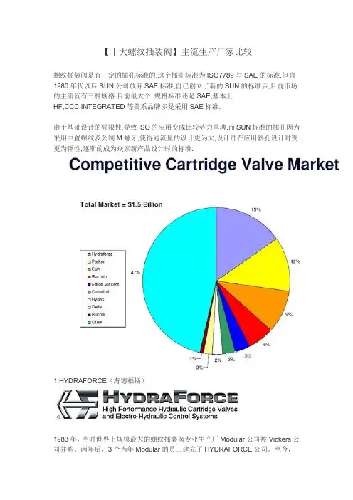
【十大螺纹插装阀】主流生产厂家比较螺纹插装阀是有一定的插孔标准的.这个插孔标准为ISO7789与SAE的标准.但自1980年代以后.SUN公司放弃SAE标准,自己创立了新的SUN的标准后,目前市场的主流就有三种规格.目前最大个规格标准还是SAE,基本上HF,CCC,INTEGRATED等美系品牌多是采用SAE标准.由于基础设计的局限性,导致ISO的应用变成比较势力单薄.而SUN标准的插孔因为采用中置螺纹及公制M螺牙,使得通流量的设计更为大,设计师在应用斜孔设计时变更为弹性,逐渐的成为众家新产品设计时的标准.1.HYDRAFORCE(海德福斯)1983年,当时世界上规模最大的螺纹插装阀专业生产厂Modular公司被Vickers公司并购。
两年后,3个当年Modular的员工建立了HYDRAFORCE公司。
至今,HF在美国的厂房达13,000m²,在英国的厂房也有4,650m²。
2003年销售额已达90MUS$,螺纹插装阀的生产规模是世界第一。
以前产品基本以中压为主,无平衡阀。
现在也已开发了很多高压的阀。
孔型以ICC 系列为主。
2.SUNSUN公司建立于1970年。
目前在美、英、德、法、韩、印多处有子公司。
1998年与台湾橡达公司合作,在上海松江建立了一个合资子公司。
2011年初退出了合资,建立了自己在中国的销售公司。
橡达公司仍然是SUN产品的代理商。
2004年螺纹插装阀的产能就达到5.8 万件/周。
2010年销售额达到了150MUS$,税后纯利润达12%。
公司销售收入约75%来自螺纹插装阀,25%则来自阀块和集成块。
产品约70%供应移动液压,30%固定液压。
孔型自成一格,公制英制螺纹兼有。
3.Sterling(斯特林)母公司在英国的Crewkerne。
以前生产汽车零件,60年代后期开始生产螺纹插装阀。
90年代初,美国Waterman公司的主任设计师Kolchinski先生到了Sterling公司美国分部,开始研发电磁阀。
【十大螺纹插装阀】主流生产厂家比较螺纹插装阀是有一定的插孔标准的.这个插孔标准为ISO7789与SAE的标准.但自1980年代以后.SUN公司放弃SAE标准,自己创立了新的SUN的标准后,目前市场的主流就有三种规格.目前最大个规格标准还是SAE,基本上HF,CCC,INTEGRATED等美系品牌多是采用SAE标准.由于基础设计的局限性,导致ISO的应用变成比较势力单薄.而SUN标准的插孔因为采用中置螺纹及公制M螺牙,使得通流量的设计更为大,设计师在应用斜孔设计时变更为弹性,逐渐的成为众家新产品设计时的标准.(海德福斯)1983年,当时世界上规模最大的螺纹插装阀专业生产厂Modular公司被Vickers公司并购。
两年后,3个当年Modular的员工建立了HYDRAFORCE公司。
至今,HF在美国的厂房达13,000m²,在英国的厂房也有4,650m²。
2003年销售额已达90MUS$,螺纹插装阀的生产规模是世界第一。
以前产品基本以中压为主,无平衡阀。
现在也已开发了很多高压的阀。
孔型以ICC 系列为主。
SUN公司建立于1970年。
目前在美、英、德、法、韩、印多处有子公司。
1998年与台湾橡达公司合作,在上海松江建立了一个合资子公司。
2011年初退出了合资,建立了自己在中国的销售公司。
橡达公司仍然是SUN产品的代理商。
2004年螺纹插装阀的产能就达到万件/周。
2010年销售额达到了150MUS$,税后纯利润达12%。
公司销售收入约75%来自螺纹插装阀,25%则来自阀块和集成块。
产品约70%供应移动液压,30%固定液压。
孔型自成一格,公制英制螺纹兼有。
(斯特林)母公司在英国的Crewkerne。
以前生产汽车零件,60年代后期开始生产螺纹插装阀。
90年代初,美国Waterman公司的主任设计师Kolchinski先生到了Sterling公司美国分部,开始研发电磁阀。
95年形成全系列。
MTechnical ReferenceHIC manifold design guidelines, tooling,torque specifications, port and cavity dimensionsT echnical Reference Section ContentsMReviewing CircuitAll designs begin with a sche-matic circuit design inspired by the application. Before the planning stage, review the design utilizing the following steps:• Match schematic symbols to model codes.• Note size and cavity of each valve and write it on schematic.• Note port numbers of the valves and write them on schematic.• Note manifold port types and sizes specified by customer.• Note pressure, flow and material of manifold block (steel or aluminum).Circuit questions should be answered by the customer before beginning a design. It is also recommended that schematic hydraulic regions or networks be color coded using color pens. Regions or net-works may be broken down in individual colors (pressure, tank, pilot, etc.) but it may be easier to design if regions are broken down into sub-regions such as pressure from port one of a solenoid valve to port two of a relief valve. Colored layers may be assigned later to match schematic circuit coloring.Initial DesignOnce the circuit is fully under-stood, it is advisable to lay the design out by hand first. Things to consider while plan-ning the design are:• Block size is often specified by customer.• Specify an overallenvelope size, in addition to the specified block size. Overall envelope size includes block size and any valves or fittings protruding from the manifold block.• Restrictions specified for a mounting surface of the manifold block. Valves and ports may be restrictedfrom a particular surface.• Specify mounting holes, threaded holes and thru holes (if necessary).• Arrange valves in a logical manner. Valves and ports in the same regions should be located in close proximity to each other.• Eliminate as many turns in the regions as possible to reduce the number of cross drill holes or construction lines. This helps keep pressure drops ( D P) andmanufacturing costs down.Material SizesTo obtain an optimal cost man-ifold it is desirable to select a standard material size for the manifold, compare the block size with the standard mate-rial size table. See Standard Material Sizes (page M-5). If a standard size is not available, a cut plate may be used. Hydraulic SchematicIf a schematic is desired on the assembly, it may be cre-ated from existing symbols. As an alternative, the entire circuit may be created outside of an assembly and imported as a symbol (block). All of the Vickers screw-in cartridge valves have schematic sym-bols which can be found in the SICV Cartridge Valve Library of Symbols CD, used in conjunc-tion with AutoCad software. Schematic symbols not found in the library may be created on an “as needed” basis.Accurate DesignAll dimensions on CAD design must be accurate and to scale in order to be utilized by CAM software in conjunction with CNC machine tools. Manually or interactively modifieddimension cannot be tolerated.Example:Note: Failure to ensure thatCAD dimensions are accurate and to scale may result in improper machinery by CNC Machine Tools.Datum PointThe datum point or origin point (0,0,0) on machining drawings is the upper left corner when facing the front view.Assembly Dimensioning Dimension all ports, mount-ing holes and overall envelope size.External ClearancesAllow enough room for clear-ance around solenoid coils, handknobs, levers and wrench clearance for fittings. If 90° elbow fittings are to be used, some may be required to swing a full 360 arc.Assembly NotesNotes are added for standard or special assembly, handling, or shipping instructions, as well as special stampings.Port T ableInclude a port table with names and sizes of all ports.Standard T oolingIn order to obtain fastturnaround on designs, limit the tooling used to that listed in the standard tooling table. See Preferred Tooling for Machining Manifolds (page M-6).General Guidelines forHydraulic Integrated Circuits (HIC)professional in the design of manifold blocks and related hydraulic systems. It is the designer’s responsibility to verify the adequacy of thedesign through approporate verifications, review and test-ing of the final design.Always “square up” the raw block before machining the cavities, ports and holes. This is to eliminate any potential “drill walk” which leads to scrapped manifolds. When squaring up a block, remove approximately 0.015” of material from each face for Aluminum blocks and 0.030” of material from each face for steel blocks. This is done to ensure that all six faces are parallel or perpendicular. Finished machining shouldreflect the squared up dimen-sions. See Standard Material Sizes (Table 1).Example: 4.0” x 5.0” x 6.0” (101.6 mm x 127 mm x 152.4 mm) block will be dimen-sioned to 3.97” x 4.97” x 5.97” (100.8 mm x 126.2 mm x 151.6 mm)Creation of MachiningT able Create a machining operation table or bore chart. Machining depths are given from the sur-face of the block. List all drill depths, mills, taps and form tools in the machining table. Call out drill depths at the shoulder depth of the drill, not to the drill point depth.All machining depths are to the corner of the full diameter as opposed to the drill point. All depths are measured from the face plane (surface) of a manifold block.Avoid any drill depths greater than 25 diameters.Additional line lengths may result in increasing pressure drops.Machining NotesMachining notes are to beadded for standard or special machining, handling and ship-ping instructions.DrillingsDrillings that go completely through a cavity port area should be on the center axis of the cavity wherever possi-ble; see Figure (a). Otherwise it should intersect the cavity tangent to the outside diam-eter of the bore it connects with; see Figure (b).Note: Breaking into a cavity at some point in between these recommended areas will lead to drill walk and can result in a high scrap rate, as well as premature drill breakage.All SAE ports and cavities have spotface depths of .031” (.8 mm) unless otherwise speci-fied. BSPP ports have spotface depths of .060” (1.5 mm) unless otherwise specified.CounterboresIn counterbore cases, the actu-al cavity spotface is located at the depth of the counterbore. When counterbore depths are greater than 0.125”, the follow-ing diameters should be used:Use of Expander Plugs and Zero Leak Gold SAE O-Ring PlugsOn small HIC packages, expander plugs can be used to block off construction drill-ing at the surface of a face. Larger than a 12mm expander plug are not recommended in aluminum. Any construction drillings larger than 0.4” (10 mm) are plugged with zero leak gold SAE O-Ring plugs (internal hex type). The machin-ing callout for these plugs can be either the industry standard SAE straight thread O-ring boss port configuration or the straight thread O-ring boss short port configuration. Refer to Port Dimensions (page M-9 and M-10).Surface T reatmentsAny manifold face that calls for a surface mounted (gas-ket mounted) valve such as a DG4V type directional control valve, or a pump or motor interface, should have a mini-mum roughness callout of 63 microinches (.0016mm) and a flatness callout of .002”(.05mm). See examples below.To prevent corrosion, steel manifolds are oil dipped or coated with rust protec-tive fluid, unless otherwise specified. To prevent oxidation, aluminum manifold blocks are gold anodize, unless oth-erwise specified. Aluminum manifolds where the internally grounded coil is used should not be anodized. Prototypes are supplied without surface treatment.Datum Point Example in orthographic third angle projection:General Guidelines forHydraulic Integrated Circuits (HIC)MWall ThicknessFor pressures up to 3000 psi (210 bar), aluminum may be used, for pressures above 3000 PSI (210 bar). Dura-Bar cast iron manifold material is recommended.Larger cavities or bores require a greater wall thick-ness.The table below shows recommended minimum wall thicknesses for Aluminum and Dura-Bar.general guidelines will notguarantee the manifold will survive any finite number of cycles. The only way to properly assure a specified life is to run a thorough testing of both burst and endurance in the actual application circuit.T able 1Standard Material SizesGeneral Guidelines forHydraulic Integrated Circuits (HIC)Creating Bill of Material – BOMDevelop a BOM that includes quantity, model codes, part numbers and descriptions of the HIC. Model codes of some valves require pressure settings. A machining opera-tion table or bore chart should be created. All plugs, orifice plugs, disks, check valves, pistons, and any other part should be included in the BOM.2 x 2 2 x3 2 x4 2 x5 2 x 62.5 x 2.5 2.5 x 3 2.5 x3.5 2.5 x 42.5 x 4.5 3 x 33 x3.53 x 43 x4.53 x 53.5 x 3.53.5 x 43.5 x 4.54 x 44 x 4.54 x 54 x 64.5 x 4.55 x 55 x 65.5 x 5.56 x 6lead to manifold failure.Preferred T ooling for Machiningof Custom ManifoldsFlat Bottom Reamer Reamer Slot BallPreferred T ooling for Machining Custom ManifoldsSense Check Took SC-4-2-75SC-4-2-88Counter Sink2" x 902" x 5"1/4" x 90Drill1/4" x 90Center Drill#5Press Tap#6-32 X#10-24 X1/4"-20 X1/4"-20 5/16"-18 5/16"-24 3/8"-16 3/8"-24 7/16"-14 7/16"-20 1/2"-13 1/2"-20 9/16"-185/8"-115/8"-183/4"-167/8"-141"-141-1/16"-121-3/16"-121-5/16"-121-5/8"-121-7/8"-121/8"-28 BSPP1/4"-19 BSPP3/8"-19 BSPP1/2"-14 BSPP3/4"-14 BSPP1"-11 BSPP1/16"-27 NPTF1/8"-27 NPTF1/4"-18 NPTF3/8"-14 NPTF1/2"-14 NPTF3/4"-14 NPTF1"-11 1/2 NPTFM10 x 1.5 MetricM10 x 1.25 MetricTap Pulley Tap1/4" - 205/16" - 247/16" - 209/16" - 183/4" - 16MT orque Specifications For Cartridge Valves and FittingsSAE and BSPP PortsSpotfaceMheighta Diameter U shall be concentric with thread pitch diameter within 0.0005 in. (0.13mm) FIR, and shall be free from longitudinal and spiral tool marks. Annular tool marks up to 100 mu in. max. are allowedb If face of boss is on a machined surface, dim. Y and S need not applyc Tap drill depths given require use of bottoming taps to produce the specified full thread lengths. Where standard taps are used, the tap drill depths must be increased accordingly.d Nominal tubing O.D. is shown for the standard inch sizes and the conversion to equivalent to mm sizes. Figures are for reference only, as any boss can be used for a tubing size, depending upon other design criteriaShort SAE portsPort DimensionsShort Port – Straight Thread O–Ring Boss – SP–**Note : To be used for SAE plugged construction holes only. Not intended to be used for external porting with standard fittings.Roughing T oolsRoughers are basically step drills which leave .030” per cutting diameter and .015” above all radii for the finish-ing reamer, with an additional .015” depth in the cavity bot-tom as clearance. The rough-ing tool is necessary to prepare the cavity for the fin-ishing reamer, which has not been designed for the primary forming or bottom cutting.Cavity For Material Model Code Part Number 2–WayC-4-2 Aluminum / Steel RT-4-2-AS-8306 02-173997C–8–2 Aluminum / Steel RT1–8–2–AS–8028 02–165580C–10–2 Aluminum RT–10–2–A–8030 889509C–10–2 Steel RT–10–2–S–8035 889510C–12–2 Aluminum / Steel RT–12–2–AS–8213 02–160625C–16–2 Aluminum RT–16–2–A–8031 889515C–16–2 Steel RT–16–2–S–8036 889516C–20–2 Aluminum RT–20–2–A–8032 565822C–20–2 Steel RT–20–2–S–8037 8895193–WayC-4-3 Aluminum / Steel RT-4-3-AS-8304 02-173271C–8–3 Aluminum / Steel RT1–8–3–AS–8291 02–162384C–10–3 Aluminum RT–10–3–A–8038 889511C–10–3 Steel RT–10–3–S–8043 889512C–12–3 Aluminum / Steel RT–12–3–AS–8217 02–153261C–16–3 Aluminum RT–16–3–A–8039 565825C–16–3 Steel RT–16–3–S–8044 889517C–20–3 Aluminum RT–20–3–A–8041 02–165581C–20–3 Steel RT–20–3–S–8046 5667063–Way ShortC–10–3S Aluminum RT–10–3S–A–8099 565824C–10–3S Steel RT–10–3S–S–8209 566703C–12–3S Aluminum / Steel RT–12–3S–AS–8220 02–113178C–16–3S Aluminum RT–16–3S–A–8040 02–165582C–16–3S Steel RT–16–3S–S–8045 566704C–20–3S Aluminum RT–20–3S–A–8042 889520C–20–3S Steel RT–20–3S–S–8047 5667054–WayC–8–4 Aluminum / Steel RT–8–4–AS–8292 02–172803C–10–4 Aluminum RT–10–4–A–8072 889513C–10–4 Steel RT–10–4–S–8073 889514C–12–4 Aluminum RT–12–4–A–8313 02-176377C–16–4 Aluminum RT–16–4–A–8074 889518C–16–4 Steel RT–16–4–S–8075 565828C–20–4 Aluminum RT–20–4–A–8076 565829C–20–4 Steel RT–20–4–S–8077 5667075–Way ShortC–12–5S Aluminum RT–12–5–A–8350 02-187301C–12–5S Steel RT–12–5–S–8358 02-187309C–16–5S Aluminum RT–16–5–A–8352 02-187303C–16–5S Steel RT–16–5–S–8360 02-187311C–20–5S Aluminum RT–20–5–A–8354 02-187305C–20–5S Steel RT–20–5–S–8356 02-187307Cavity For Material Model Code Part Number 2–WayC–4–2 Aluminum FT–4–2–A–8297 02–182339C–8–2 Aluminum / Steel FT1–8–2–AS–8070 02–112933C–10–2 Aluminum / Steel FT–10–2–AS–8048 566235C–12–2 Aluminum / Steel FT–12–2–AS–8214 02–162162C–16–2 Aluminum / Steel FT–16–2–AS–8078 565832C–20–2 Aluminum / Steel FT–20–2–AS–8079 5658333–WayC–4–3 Aluminum FT–4–3–A–8275 02–172006C–8–3 Aluminum / Steel FT–8–3–AS–8295 02–171292C–10–3 Aluminum / Steel FT–10–3–AS–8050 565834C–12–3 Aluminum / Steel FT–12–3–AS–8244 02–163001C–16–3 Aluminum / Steel FT–16–3–AS–8080 565836C–20–3 Aluminum / Steel FT–20–3–AS–8082 8893583–Way ShortC–10–3S Aluminum / Steel FT–10–3S–AS–8210 566708C–12–3S Aluminum / Steel FT–12–3S–AS–8242 02–162998C–16–3S Aluminum / Steel FT–16–3S–AS–8081 889356C–20–3S Aluminum / Steel FT–20–3S–AS–8083 8893594–WayC–8–4 Aluminum / Steel FT–8–4–AS–8296 02–171291C–10–4 Aluminum / Steel FT–10–4–AS–8052 565838C–12–4 Aluminum / Steel FT–12–4–AS–8312 02-175596C–16–4 Aluminum / Steel FT–16–4–AS–8084 566571C–20–4 Aluminum / Steel FT–20–4–AS–8085 889360.5–Way ShortC–12–5S Aluminum FT–12–5–A–8351 02-187302C–12–5S Steel FT–12–5–S–8359 02-187310C–16–5S Aluminum FT–16–5–A–8353 02-187304C–16–5S Steel FT–16–5–S–8361 02-187312C–20–5S Aluminum FT–20–5–A–8355 02-187306C–20–5S Steel FT–20–5–S–8357 02-187308Finishing Form T oolsSpeed & Feed for Aluminum 6061–T6 (T651) This information is recommended as a good starting point. Speeds and/ or feeds may be increased or decreased depending on actual machining conditions.Note: Finish form tools may require 1/2 to 1 1/2 second dwell to obtain necessary finish.Finishing T oolsThese finishing tools have been designed as preci-sion reamers for finishing operations only. They are not intended for primary forming or bottom cutting operations. Vickers recommends that a finishing tool only be used in a properly roughed hole. Failure to conform to this practicewill produce unsatisfactory size and finishes and possibly break the tool.MC–**–2(P)Dimensionsmm (inch)Cavity bores can be machined accurately in aluminum or steel. The necessary UNF , or UN threads may be machined using standard small tools, possibly already in yourmachine shop or from a local tool supplier.Either you, our customer, or Eaton can design and manufacture customized manifolds or housings dedicated to indi-vidual applications. We call the resulting valve packages Hydraulic Integrated Circuits (HIC). Cartridges selected for your application can be accom-modated in one or more HICs, according to your require-ments.WARNING For EPV-10 &CV16-10, thecavity should bemachined to the 14,29 (0.562) max diameter (dimension X) and to the maximum depth of 36,0 (1.417) (dimension J)Dimensions mm (inch)Cavity bores can be machinedaccurately in aluminum orsteel. The necessary UNF, orUN threads may be machinedusing standard small tools,possibly already in yourmachine shop or from a localtool supplier.Either you, our customer, orEaton can design and manufacture customized manifoldsor housings dedicated to indi-vidual applications. We callthe resulting valve packagesHydraulic Integrated Circuits(HIC). Cartridges selected foryour application can be accom-modated in one or more HICs,according to your require-ments.WARNINGFor EPV-10 &CV16-10, thecavity should bemachined to the 14,29 (0.562)max diameter (dimension X)and to the maximum depth of36,0 (1.417) (dimension J)C-**-2 CavityDimensions(0.0625) Runless otherwise specifiedunless otherwise specified2-way cavity with undercut (u)MC-**-3 Cavity Dimensionsunless otherwise specified unless otherwise specifiedDimensionsmm (inch)MDimensionsmm (inch)MC-**-5SCavityDimensionsDimensionsmm (inch)Cartridge Cavities IndexMOur cavities have beendesigned to achieve standard-ization based on each thread size to reduce the amount of tooling required to cover the valve range. All new designs of cartridge are made to fit the ISO recommendations forstandard cavities. The diagram below shows the sequence of tooling using tools specified in the following pages. Note: a pilot drill may be required before the form drill.Great care must be taken to ensure that the tools are inserted along the same machining axis to maintain correct concentricities, hence bodies should not be moved between operations.Operation 1Form Drill Operation 2Form Reamer Operation 3Plug T apIndexCavity A877Cavity T ools Form Drill A1161Form Reamer A1162Plug Tap 1 5/16-12 UNFCavity A879 Cavity T ools Form Drill A1040Form Reamer A1041Plug Tap3/4-16 UNFCavity A878 Cavity T ools Form Drill A885Form Reamer A1173Plug Tap7/8-14 UNFCavity A880Cavity T ools Form Drill A1302Form Reamer A1303Plug Tap1-14 UNS45.0028.00Ø26.00ØMCavity A881Cavity T ools Form Drill A1183Form Reamer A1036Plug Tap1 -14 UNFCavity A1126 Cavity T ools Form Drill AT422Form Reamer AT488Plug Tap1 5/8-12 UNFCavity A893Cavity T ools Form Drill A894Form Reamer AT491Plug Tap7/8-14 UNFCavity A3145Cavity T oolsForm Drill A3226 Form Reamer A3227 Plug Tap 1 5/16-12 UNCavity A3531Cavity T oolsForm Drill A3538 Form Reamer A3539 Plug Tap 3/4-16 UNF Cavity A3146Cavity T oolsForm Drill A3315 Form Reamer A3316 Plug Tap 1 1/8-12 UNFCavity A5302Cavity T oolsForm Drill A5668 Form Reamer A5669 Plug Tap 7/8-14 UNFMCavity A6610 Cavity T ools Form Drill AT447Form Reamer AT448Plug TapM20 x 1.5Cavity T ools Form Drill A6933Form Reamer A6934Plug Tap 1 5/16-12 UNFCavity A6701 Cavity T ools Form Drill AT482Form Reamer AT483Plug Tap3/4-16 UNF30.0Ø 26.0012.704)Cartridge CavitiesCavity A6935Cavity T oolsForm Drill AT501 Form Reamer AT502 Plug Tap 1 5/8-12 UN Cavity A7447Cavity T oolsForm Drill A8115 Form Reamer A8117 Plug Tap M27 X 2MCavity A12088Cavity T ools Form Drill A3315Form Reamer A3316Plug Tap1 1/8-12 UNFCavity A12336 Cavity T ools Form Drill A12337Form Reamer A12338Plug TapM27 X 1.5Cavity A12370Cavity T ools Form Drill A12439Form Reamer A12440Plug Tap7/8-14 UNFCavity A12196Cavity T ools Form Drill A12197Form Reamer A12198Plug TapM27 X 1.530.00Cavity A12743Cavity T ools Form Drill A12802Form Reamer A12803Plug Tap7/8”-14 UNFCavity A13098 Cavity T ools Form Drill A13099Form Reamer A13100Plug Tap1 5/8”-12 UNCavity A12744Cavity T ools Form Drill A12804Form Reamer A12805Plug Tap7/8-14 UNF34.00Ø34.00MCavity A13245Cavity T ools Form Drill A13246Form Reamer A13247Plug Tap 1 5/8”-12UNF -2BCavity A16102Cavity T ools Form Drill A3226Form Reamer A3227Plug Tap 1 5/16-12UNF -2BCavity A16927Cavity T ools Form Reamer AT1097Plug TapM10 x 1.0Cavity A20081Cavity T ools Form Drill AT2369/1Form Reamer AT2369/2Plug TapM38 x 2-6H58.00Ø51.00NOTE: T hese cavity dimensions are for installation purposes only.Cavity CVA- 22- 06- 0Cavity T ools Form Drill A8966Form Reamer A8967Plug TapM22 X 1.5Cavity CVA- 27- 04- 0Cavity T ools Form Drill A12784Form Reamer A496Cavity C-I-M18-3Cavity CVA- 20- 01- 0Cavity T ools Form Drill A8961Form Reamer A8962Plug TapM20 X 1.534.00 32.00EATON Screw-In Cartridge Valves E-VLSC-MC001-E1 September 2013M-32.A Where measurements are critical request certified drawings. We reserve the right to change specifications without notice.Cavity CVB- 22- 06- 0Cavity T ools Form Drill A8966Form Reamer A8967Plug TapM22 X 1.5ISO StandardNOTE: These cavity dimensions are for installation purposes only.CVB- 42- 04- 0Cavity T ools Form Drill BT499Form Reamer AT498Plug TapM42 X 234.00EATON Screw-In Cartridge Valves E-VLSC-MC001-E1 September 2013M-33.AMWhere measurements are critical request certified drawings. We reserve the right to change specifications without notice.- Additional products, product lines, and services offered by Eaton -Sectional Design for Multiple ConfigurationsEaton’s MDG mobile directional control valve uses a modular, versatile design based on our proven Vickers ® DG4V3 design. Eaton ® MDG valves, trulydesigned for mobile applications, offer the traditional benefits of a stackable mobile valve and provide further value as circuit options for mobile manifoldsystems. T his same versatility and flexibility applies to system applications, making it your best value for customized, multi-functional circuits.For more information, contact your local Eaton distributor, call us at 800-547-7805 or visit us on the web at: /hydraulics.MDG Mobile ValveVersatile, Proven, Best ValueSame day solutions with our Build Kit Program!。
Eaton CorporationHydraulics Operations14615 Lone Oak RoadEden Prairie, MN 55426Tel: (952) 294-7992Fax: (952) 294-2026Email:********************Date March 11, 2008For Release ImmediatelyContact Lynn Soule, (952) 294-7992Eaton’s Hydraulic Operations Adds New Manual Lever ValveTo Its Vickers Line Of Screw-In Cartridge ValvesEDEN PRAIRIE, Minn. … Diversified industrial manufacturer Eaton Corporation has added manual lever valves (MLV9) to its line of Vickers® screw-in cartridge valves (SiVCs). Intended for both mobile and stationary industrial applications at pressures up to 210 bar (3,000 psi), the new valves are designed to be easily integrated into custom manifold blocks, or manifold circuit designs (MCDs), which combine multiple cartridge valves in a common manifold block.MCDs offer substantial cost savings and can be as extensive as necessary to meet the most complex hydraulic applications, or as simple as a few cartridges. Among the advantages offered by the new MLV9 series of manual lever valves when used independently or included in an MCD:•Fewer potential leakage points for a cleaner, safer application environment;•Very neat, compact assemblies that save weight and space; and•Highly efficient, low maintenance systems with improved productivity via optimized circuitry.Ideal for such rugged environments as off-highway equipment, wind power and steel mills, Eaton's new manual lever valves can replace other manual valves including pull/push-to-shift, 3-position, 4-way, tandem center, mobile sectional, and manually-operated industrial models. They are offered in open center, closed center, tandem pool, and motor spool configurations.Eaton/Page 2The motor spool features an open center which permits a motor to freewheel when the valve is centered, rather than being brought to a stop. Motor spools can also be used for directional control of cylinders in applications in which the cylinder is free to move when not being extended or retracted."The handle is extremely robust," explained Thelma Gutierrez-Anderson, Eaton’s Hydraulics Operations product manager, screw-in cartridge valves. "While the same functionality can be achieved with other types of valves, ease of use makes the MLV9 the better choice."The new MLV9 series manual lever valves are part of Vickers’ range of high-performance SiVCs which covers sizes up to 350 bar and 150 l/min. with direct acting, proportional and solenoid, flow control, pressure control and directional control models. All Vickers SiCVs are National Fluid Power Association rated to guarantee high performance.Eaton’s Hydraulics Operations is a business segment of Eaton’s Fluid Power Group. The business is a worldwide leader in the design, manufacture and marketing of a comprehensive line of reliable, high-efficiency hydraulic systems and components for use in mobile and industrial applications. Mobile and industrial markets include agriculture, construction, mining, forestry, utility, material handling, earthmoving, truck and bus, machine tools, molding, primary metals, automotive, power generation, port machinery and entertainment. Eaton’s Hydraulics Operations provides customer-driven solutions under brand names such as Aeroquip®, Boston®, Char-Lynn®, Eaton®, Hydro-Line®, Vickers® and Weatherhead®. For more information, visit .Eaton Corporation is a diversified industrial manufacturer with 2007 sales of $13.0 billion. Eaton is a global leader in electrical systems and components for power quality, distribution and control; fluid power systems and services for industrial, mobile and aircraft equipment; intelligent truck drivetrain systems for safety and fuel economy; and automotive engine air management systems, powertrain solutions and specialty controls for performance, fuel economy and safety. Eaton has 70,000 employees and sells products to customers in more than 150 countries. For more information, visit .###。