OTT-M300雨滴谱仪使用手册
- 格式:pdf
- 大小:7.57 MB
- 文档页数:47

警告感谢您购买了本公司的VICTOR 3700B智能型等电位测试仪/直流低电阻测试仪,为了更好地使用本产品,请一定:——详细阅读本用户手册。
——严格遵守本手册所列出的安全规则及注意事项。
u本仪表根据IEC61010安全规格进行设计、生产、检验。
u任何情况下,使用本仪表应特别注意安全。
u注意本仪表机身的标贴文字及符号。
u仪表设计了过压保护,但应尽可能避免直接测量带有市电的导体。
u使用前应确认仪表及附件完好,仪表、测试线绝缘层无破损、无裸露、无断线才能使用。
机壳或测试线发生断裂而造成金属外露时,请停止使用。
u测量过程中,严禁接触裸露导体及正在测量的回路。
u测量前请先确认FUNCTION功能旋钮所处的位置。
u确认导线的连接插头已紧密地插入仪表接口内。
u请勿在易燃性场所测量,火花可能引起爆炸。
u请勿于高温潮湿,有结露的场所及日光直射下长时间放置和存放仪表。
u若仪器潮湿,请干燥后再保管。
u电池电压低符号显示,请及时充电,每次充电2小时。
u测试仪长时间放置不使用,请每1~2个月给电池充电一次。
u本仪表无自动关机功能,使用完后请关机,以免电池耗尽。
u使用、拆卸、校准、维修本仪表,必须由有授权资格的人员操作。
u由于本仪表原因,继续使用会带来危险时,应立即停止使用,并马上封存,由有授权资格的机构处理。
u仪表及手册中的”安全警告标志,使用者必须严格依照本手册内容进行安全操作。
目录一.简介 (3)二.技术规格 (3)三.仪表结构 (5)四.操作方法 (5)1.开关机 (5)2.背光控制 (5)3.时钟设置 (5)4.报警设置 (6)5.数据锁定/存储 (6)6.数据查阅/删除 (6)7.测试功能切换 (6)8.线阻校验 (7)9.等电位(电阻)测试 (7)10.导线长度测试 (8)11.数据上传 (8)五.电池充电 (9)六.装箱单 (9)一.简介VICTOR 3700B智能型等电位测试仪,又名:直流低电阻测试仪、直流电阻测试仪、欧姆表、微电阻计等,采用精密四线法测试,准确可靠。
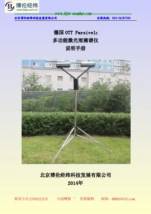
德国OTT Parsivel2多功能激光雨滴谱仪说明手册北京博伦经纬科技发展有限公司2014年1概述德国OTT Parsivel2激光雨滴谱仪是一种现代化的以激光技术为基础的光学测量系统。
传感器采用原装德国进口,它可以全面而可靠地测量各种类型的降水。
液态降水类型粒径的测量范围为0.2毫米到5毫米,固态降水类型粒径测量范围为0.2毫米到2.5毫米。
它可对速度为0.2到20米每秒降水粒子进行测量。
可测量的降水类型如下:毛毛雨、小雨、雨、雨、雨夹雪、雪、米雪、冻雨、冰雹。
降水测量是通过一个专门设计的特殊的传感元件来实现的。
它可以检测肉眼可见的地面以上一米降水。
设备具备有线和无线通信传输,数据获取和存储是通过一个快速的数字化信号处理器完成的。
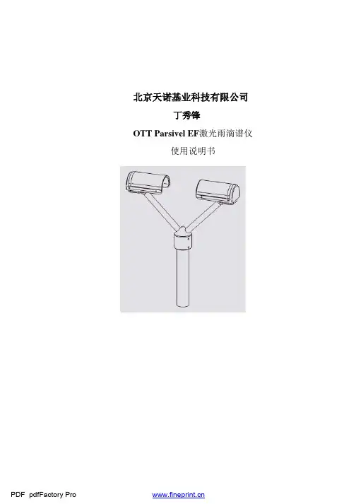
2基本工作原理德国OTT Parsivel2激光雨滴谱仪的工作原理基础是一个能够发射水平光束的激光传感器。
其变送器和接收器集成在防护罩中。
图2-1工作原理图当激光束里没有降水粒子降落穿过时,最大电压为接收器的输出电压。
降水粒子穿过水平光束时以其相应的直径遮挡部分光束,因而产生输出电压。
我们通过电压的大小来确定降水粒子的直径大小。
降水粒子的下降速度是根据电子信号持续的时间推导出来的。
电子信号的持续时间为降水粒子开始进入光速到完全离开光束所经历的时间。
根据上述的决定量可以推算出降水滴谱、降水类型、降水动能、降水强度、雷达放射率和大气的能见度等信息。
安装在传感器头上的防雾装置能够防止降水粒子偏离防护罩、掉入激光束造成测量误差。
3系统组成德国OTT Parsivel2激光雨滴谱仪主要由气象传感器单元、数据采集控制单元、数据通信单元、供电单元、电源和通信防雷单元以及观测软件等几个部分组成。
数据处理控制中心气象传感器数据观测处理平台气象数据采集本场数据传输前端数据简化与综合监控与维护网络与通信其它共享平台通信防雷图3-1系统总体框图图3-2传感器实物图1.供电系统为保证系统稳定连续的电力供应,除降水现象仪本身采用了低功耗设计外,设备采用UPS 不间断稳压电源供电,保证了系统的长时间稳定可靠工作。
OTT 气泡水位计操作手册导读:就爱阅读网友为您分享以下“OTT 气泡水位计操作手册”资讯,希望对您有所帮助,感谢您对92to 的支持!操作手册气泡传感器OTT CBS技术参数如有更改,恕不提前通知。
目录1、供货范围................................................................................................... ........................................................42、订货号................................................................................................... .............................................................43、介绍................................................................................................... (5)3.1 功能................................................................................................... (6)3.2 LED 状态灯................................................................................................... .................................................6 4、安装OTT CBS................................................................................................ (7)4.1 OTT CBS的安装准备工作................................................................................................... .. (7)4.2 固定OTT CBS................................................................................................ . (7)4.3 将测量管连接到OTT CBS 上................................................................................................... ..............8 5、安装气泡室................................................................................................... . (9)5.1 安装供地表水使用的气泡室................................................................................................... (9)5.2 安装供地下水使用的气泡室................................................................................................... ................9 6、连接OTT CBS................................................................................................ . (12)6.1 电源连接................................................................................................... (13)6.2 使用SDI-12通讯接口将OTT CBS与任意数据记录器连接起来 (13)6.3 使用4...20mA通讯接口将OTT CBS与任意数据记录器连接起来. (13)6.4 使用SDI-12通讯接口将OTT CBS与Logo Sens2或DuoSens 连接起来 (14)6.5 使用4...20mA通讯接口将OTT CBS与Logo Sens2或DuoSens 连接起来......................16 7、激活清洗功能................................................................................................... .............................................18 8、使用DIP 开关设置运行参数................................................................................................... . (19)8.1 设置SDI-12通讯接口的类型................................................................................................... .. (19)8.2 设置4...20mA通讯接口对液位或深度测量的测量类型.. (20)8.3 缩放4...20mA通讯接口的量程................................................................................................... . (20)8.4 设置4...20mA通讯接口的测量系统. (2)18.5 设置4...20mA通讯接口对水位或压力测量的测量类型 (21)8.6 运行参数的出厂设置................................................................................................... ............................21 9、SDI-12的命令和响应................................................................................................... . (22)9.1 标准命令................................................................................................... .. (22)9.2 高级的SDI-12命令................................................................................................................................23 10、在4...20mA通讯接口上确定最大负载 (24)11、执行维护工作................................................................................................... ..................................25 11.1 激活清洗功能................................................................................................... ........................................25 11.2 清洗气泡室................................................................................................... ............................................25 11.3 测试测量管................................................................................................... ............................................25 12、LED 状态指示灯................................................................................................... .............................26 13、旧装置的旧装置的处置信息处置信息................................................................................................... .........................26 14、技术参数................................................................................................... .. (27)1 供货范围OTT CBS - 1个气泡传感器OTT CBS,可以与内径/外径为4mm/2mm的测量管进行连接。
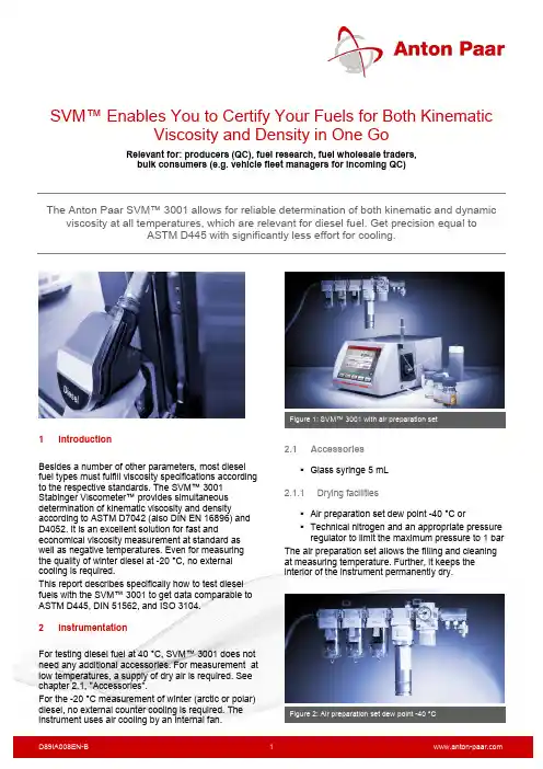
SVM™ Enables You to Certify Your Fuels for Both KinematicViscosity and Density in One GoRelevant for: producers (QC), fuel research, fuel wholesale traders, bulk consumers (e.g. vehicle fleet managers for incoming QC)The Anton Paar SVM™ 3001 allows for reliable determination of both kinematic and dynamicviscosity at all temperatures, which are relevant for diesel fuel. Get precision equal toASTM D445 with significantly less effort for cooling.1IntroductionBesides a number of other parameters, most diesel fuel types must fulfill viscosity specifications according to the respective standards. The SVM™ 3001 Stabinger Viscometer™ provides simultaneous determination of kinematic viscosity and densityaccording to ASTM D7042 (also DIN EN 16896) and D4052. It is an excellent solution for fast andeconomical viscosity measurement at standard as well as negative temperatures. Even for measuring the quality of winter diesel at -20 °C, no external cooling is required.This report describes specifically how to test diesel fuels with the SVM™ 3001 to get data comparable to ASTM D445, DIN 51562, and ISO 3104.2 InstrumentationFor testing diesel fuel at 40 °C, SVM™ 3001 does not need any additional accessories. For measurement at low temperatures, a supply of dry air is required. See chapter 2.1, "Accessories".For the -20 °C measurement of winter (arctic or polar) diesel, no external counter cooling is required. The instrument uses air cooling by an internal fan.2.1Accessories ▪ Glass syringe 5 mL2.1.1Drying facilities▪ Air preparation set dew point -40 °C or▪ Technical nitrogen and an appropriate pressure regulator to limit the maximum pressure to 1 bar The air preparation set allows the filling and cleaning at measuring temperature. Further, it keeps the interior of the instrument permanently dry.Figure 2: Air preparation set dew point -40 °C2.2 Installation For installing an SVM™ 3001 respectively the airpreparation set or a source of technical nitrogen, refer to the SVM™ 3001 Reference Guide.3 Measurement of diesel fuel 3.1Instrument preparationFor measurements in the standard temperature range, no special preparation is required. The cells should be clean, dry, and leak-tight. Perform regular checks and do preventive maintenance.For measurements at low temperatures, remove the measuring rotor. Purge the inside of the cell block for a few minutes with dry air to keep this tube dry. Insert the measuring rotor immediately afterwards and close the measuring cell lock. Now purge the measuring cell with dry air for a few minutes before cooling down to remove any traces of air humidity from the cells.3.2 SettingsFor measurements according to ASTM D7042▪ Method: Standard▪ Precision class: Precise ▪ RDV limit: 0.10 %▪ RDD limit: 0.0002 g/cm³ ▪ Automatic prewetting: yes ▪ Drying time:– built-in air pump, at 40 °C: 70 s– compressed dry air, 0.3 bar, at -20 °C: 60 sFor measurements according to ASTM D4052▪ Method: Standard▪ Precision class: Ultraprecise ▪ RDV limit: 0.10 %▪ RDD limit: 0.0001 g/cm³ ▪ Automatic prewetting: yes ▪ Drying time:– built-in air pump, at 40 °C: 80 s– compressed dry air, 0.3 bar, at -20 °C: 60 sAir preparation set – pressure▪ To prevent the cells from warming up too much when drying, 0.3 bar are sufficient.▪ Slow flow (few liters/min) to keep the interior of the instrument dry. Hose connected to the DRY AIR INTERNAL nozzle on the rear of SVM™ 3001.3.3 CalibrationBefore measuring the samples, perform a calibration. If required, apply a calibration correction to improve the reproducibility. Use a standard in the viscosity range of your diesel fuel samples. This can be a certified standard or a house-internal standard with kinematic viscosity values. In any case, you need reliable kinematic viscosity values at the measuring temperatures.To perform a calibration (correction), refer to the SVM™ 3001 Reference Guide.3.4 Sample preparationIf the sample is not freshly drawn from a production line or other reservoir, you can improve therepeatability by homogenizing the sample before taking the test specimen:▪ Fill approximately 100 mL of sample into a glass flask.▪ Close the flask and the original container immediately to avoid evaporation.▪ Stir the sample on a magnetic stirrer at low speed for approximately 5 minutes.3.5 FillingAlways use a glass syringe.The glass syringe supplied with the instrument has a Luer-Lock connector. Remove the filling hose from the measuring cell lock and attach an adapter Luer/UNF PEEK instead. Ensure that the measuring cells are leak tight, clean and dry.Fill at least 1.5 mL as first filling. After prewetting refill at least 1 mL or until the sample in the waste hose is free of bubbles. Sample volume: typically 5 mL3.6 Cooling times and sample throughput Sample throughput:▪ 40 °C: approx. 12 samples/hour ▪ -20 °C: approx. 8 samples/hourCooling times:Generally, the cooling time depends on the measuring temperature, and the ambient temperature,respectively, on the bath size and performance of the thermostat.When starting from room temperature and using air cooling, the SVM™ 3001 is ready for measurement at -20 °C after approximately 20 minutes.For better cooling performance or higher ambient temperatures (> 25 °C), use an external cooling circulator. Find suitable models in the SVM™ X001 Product Description List.3.7 Cleaning 3.7.1SolventsPetroleum benzine (hydrocarbon solvent, blend of mainly C7, C8, C9 n-alkanes) with a boiling range of 100 °C to 140 °C is a universal solvent for cleaning over a wide temperature range. Use this solvent as first solvent to remove the sample. To improve drying at low temperatures, use approximately 2 mL of n-heptane or n-hexane as second solvent.▪ Typical amount first solvent: 6 mL3.7.2Cleaning guidelinesThere is no special cleaning procedure required, as the sample is rather easy to remove. Consider the following hints:▪ Open the cleaning screen. Observe it during the cleaning procedure. It gives helpful information on the cleaning and drying status of the cells during the entire procedure.▪ Remove the sample from the cells by sucking it back into to syringe. This avoids leaking. ▪ For cleaning, a plastic syringe can be used. ▪ When using a single solvent, it must be volatile enough to dry up without leaving residues in the cells.▪ When using two solvents, perform a final flush with a drying solvent to remove any residues. ▪ Dry the measuring cells until the cleaning value turns green and stays steadily green. ▪For details, see the SVM™ X001 Instruction Manual or Reference Guide.4 ResultsThis report compares measurements of diesel fuel (DF-2) at 40 °C performed with SVM™ 3001(ASTM D7042) and with kinematic glass capillary viscometers (ASTM D445).Table 1: Comparison of ASTM D445 and D7042 results5References▪ ASTM D7042: Standard Test Method for Dynamic Viscosity and Density of Liquids by Stabinger Viscometer (and the Calculation of Kinematic Viscosity)▪ ASTM D4052: Standard Test Method for Density, Relative Density, and API Gravity of Liquids by Digital Density Meter▪ EN 16896: Petroleum products and relatedproducts - Determination of kinematic viscosity - Method by Stabinger Viscometer ▪ EN ISO 3104: Petroleum products -Transparent and opaque liquids - Determination of kinematic viscosity and calculation of dynamic viscosity▪ ASTM D445: Standard Test Method forKinematic Viscosity of Transparent and Opaque Liquids (and the Calculation of Dynamic Viscosity)▪ GOST 33-82 - Nefteprodukty. Metod opredeleniia kinematicheskoi i raschetdinamicheskoi viazkosti (Petroleum products. Method for determination of kinematic viscosity and calculation of dynamic viscosityContact Anton Paar GmbH Tel: +43 316 257-0**************************** APPENDIXAppendix A. About diesel fuelWhat is diesel fuel?Generally, diesel fuel is liquid fuel to power diesel engines used mainly in road vehicles, watercraft, rail vehicles, and stationary engines. It can be produced from different types of feedstocks.Petroleum dieselThis is a hydrocarbon mixture with approximately 8 to 21 carbon atoms per molecule. It is obtained by fractional distillation of crude oil under atmospheric pressure between 200 °C and 350 °C. Additionally, it contains additives. The most common grade is diesel fuel no. 2. An important parameter for the quality of a diesel fuel is the cetane number. The minimum cetane number is 51 according to EN 590. Typically, diesel fuels have a cetane number between 51 and 56. Higher cetane numbers are an indicator of better ignitability of the fuel when injected into the cylinder filled with hot compressed air. Viscosity is generally an important parameter for diesel fuel. Fuel, which is too highly viscous, can cause damage in the fuel pump (e.g. cam and follower wear) due to higher pressure. Too low viscosity may lead to a lack of lubrication. Viscosity also influences the fuel delivery rate and the atomization of the fuel during injection. BiodieselBiodiesel or FAME (fatty acid methyl ester) is an alternative diesel fuel derived from renewable feedstocks such as used cooking oils, rapeseed oil, animal fat, or soybean oil. It is obtained by transesterification. Pure biodiesel is known as B100. Mixtures of biodiesel with petroleum diesel are tagged as BXX, where XX is the percentage of biodiesel in the blend. The advantages of biodiesel compared to petroleum diesel are reduction of most exhaust emissions, improved biodegradability and a higher flash point.By the way – petroleum diesel also contains up to 7 % biodiesel according to country-specific laws.For transesterification, the oils or fats are mixed with methanol or ethanol and other additives. The ester linkages of these oils or fats (triglycerides, esters of free fatty acids) are cracked at normal pressure at approximately 60 °C. Then the fatty acids are transesterificated with the methanol or ethanol. The glycerin formed in this process is separated from the biodiesel. The transesterification process decreases biodiesel viscosity significantly compared to the basic material. The cetane number (a measure for the ignition performance) is increased. Synthetic dieselSynthetic diesel is not the same as biodiesel. It can be produced from any feedstock which contains carbon. This can be biomass, bio gas, natural gas or coal. The raw material is gasified into synthesis gas. After purification, this gas is converted into synthetic diesel fuel by variants of the Fischer-Tropsch process (originally, the Fischer-Tropsch synthesis was developed in the 1920s to produce fuel from coal). Depending on the feedstock, different types of production processes are known: biomass-to-liquid (BTL), gas-to-liquid (GTL), or coal-to-liquid (CTL), respectively. The most common variant is GTL. When using coal as feedstock, a disadvantage is a large release of greenhouse gases.Synthetic GTL diesel is free of sulfur, aromatics, nitrogen and others. It is not toxic and produces significant cleaner emission during combustion than diesel fuel refined from crude oil. Synthetic diesel has a high cetane number of 60, GTL diesel of 75 to 80. These fuels can be used in the same regions where diesel fuel is used, even in arctic zones.Winter dieselIn cold areas, diesel fuel tends to form solid wax particles, which thicken the fuel, clog fuel filters and injectors. Winter diesel uses special additives to lower the cold filter plugging point (CFPP, temperature at which wax particles form). The additives do not prevent the formation of wax particles, but they prevent the formation of large wax flakes. This means that the fuel stays liquid at lower temperatures. Basis for winter diesel can be petroleum diesel, a mixture of petroleum and biodiesel, or synthetic diesel. Depending on the area where it is used, one can distinguish between two types, winter diesel and arctic (polar) diesel.Diesel for cold climate zones is defined via the CFPP. EN 590 additionally states a viscosity limit at -20 °C. Appendix B. Why measure viscosity?Influence of viscosityViscosity is an essential parameter for the correct function of a diesel engine, as it directly influences the operation of the fuel injection system and of the fuel pump. The viscosity of biodiesel influences the lubrication of injection nozzle and injection pump, further the atomization of the fuel.Accurate monitoring of viscosity can serve to evaluate the quality of diesel fuels.Fuel injectionUnder high pressure, diesel fuel is injected directly or indirectly into the combustion chamber of a diesel engine via nozzles. The injection system produces a fine spray of fuel droplets, which evaporate rapidly when mixed with the hot compressed air in the cylinder. Droplet size and spray pattern are directly influenced by the fuel viscosity.If the viscosity is too high, the fuel droplets are not fine enough, which causes a worse combustion, more smoke and higher emissions. Too low viscosity can cause hot start problems or injector leakage.Fuel pump – performance and lubricationA too low viscosity can lead to a lack of lubrication of the fuel pump and consequently to increased wear or a failure. Too high viscosity at low temperatures will lead to problems in fuel conveyance – the higher the viscosity, the harder the pump must work to provide a constant fuel flow rate – and damages of the fuel injection pump (e.g. a seizure).Blending of diesel with biodieselFigure 3: Viscosity depending on biodieselconcentration, shows a summary result at 40 °C for diesel fuels with different contents of biodiesel. The viscosity of the product increases with increasing percentage of biodiesel.Figure 3: Viscosity depending on biodiesel concentrationThe viscosity curves follow a trend of power law according to the following equation (here shown for kinematic viscosity only): Equation 1:y = 2.3559 e 0.0059xy ... kinematic viscosityx ... % percentage by weight biodiesel in diesel fuelThis equation yields the calculation in the below table:Table 2: Viscosity calculation from equation 1This table shows, that if the percentage of biodiesel in diesel fuel does not exceed 5 %, both the limits of ASTM D975 can be met (see Table 3) and theenvironmental quality can be improved by adding 1 to 5 % of biodiesel without negative effects on efficiency and function of the engine.Viscosity parameters and typical viscosities The viscosity parameter for diesel fuels is kinematic viscosity. Depending on grade and usage, it is measured at +40 °C, further for winter qualitiesat -20 °C. The relevant specifications are stated in the respective standards and regulations.Table 3: Diesel fuel types – viscosity specifications* The viscosity limits of the ready blend product of biodiesel with petroleum diesel must not exceed the values given in ASTM D975. ** Maximum kinematic viscosity at -20 °C if the CFPP (cold filter plugging point) is -20 °C or lower. This applies to the CFPP classes F and 0 to 4 (see DIN EN 14214, EN 116/IP 309).Diesel fuel specification standards ▪ ASTM D975: Standard Specification for Diesel Fuel Oils▪DIN EN 14214: Automotive fuels. Fatty acid methyl esters (FAME) for diesel engines - Requirements and test methods▪ASTM D6751: Standard Specification forBiodiesel Fuel (B100) Blend Stock for Distillate Fuels▪ EN 116 / IP 309 Determination of CFPP▪MIL-DTL-16884M: Detail Specification of Fuel, Naval Distillate, F-75/F-76▪ GOST R 52368: Diesel Fuel Euro Specifications ▪ JIS K 2204: Diesel FuelLow temperature measurement – comparison to conventional viscosity measurementFor low temperature applications (-20 °C), there are generally two types of instruments available. Either large viscometer baths for simultaneously testing two or four capillaries, or compact desktop mini viscometers with 10-fold range capillaries. All these low temperature capillary viscometersrequire cooling liquids that stay clear at temperatures even lower than the measuring temperature. Such liquids usually are difficult to handle. They are either expensive (silicone oils) or have a low flash point (methanol) and involve a safety risk. On the contrary, even for testing at -40 °C, the counter cooling liquid for SVM™ 3001 is operated only at -5 °C, which permits the use of a low-price water/glycol mixture. Nor can these glass capillary viscometers perform cleaning and drying at the low measuringtemperatures – condensation is in the way. One automatic mini viscometer solves this problem by heating the apparatus for the cleaning procedure. However fast this is done, it still consumes more time and energy than the SVM™ 3001 with the air drying equipment.The following tables give an overview of the main differences between SVM™ 3001 and low temperature glass capillary viscometers:Table 4: Compare SVM™ 3001 to other viscometer baths。

Technology Made Easy...使用说明书PC 300防水便携式 pH/电导率/TDS/温度仪器35631-0068X248908ver. 2.2 Oct 02前言本手册说明了CyberScan PC 300手提式仪器的使用方法。
它有两种功能:首先是循序渐进的帮助用户学会如何去操作仪器,其次它可作为一本方便的使用指南。
本手册涵盖CyberScan PC 300的多种应用,如果您在使用仪器中有任何疑问,请立即与离您最近的Eutech/ Oakton授权经销商联系。
Eutech/ Oakton 仪器公司将不承担由于使用不当引起损坏和故障的任何责任。
本手册的内容将随着科技进步而改变,此种情况Eutech/Oakton仪器公司将不专门通知客户并不承担由此引起的任何责任。
版本 © 2000 年2月Eutech / Oakton仪器有限公司版权所有2002年10月修订目录1简介12显示和键盘功能22.1显示2 2.2键盘33准备工作43.1安装电池4 3.2电极信息54校正74.1仪器校正的重要信息7 4.2校正的准备工作8 4.3pH校正8 4.4电导率校正11 4.5TDS校正14 4.6电导率标准和TDS因子的校正 15 4.7温度校正165测量18 5.1pH测量18 5.2电导率或TDS的测量216锁定功能277高级设置功能 28 7.1高级SETUP模式总括30 7.2P1.0:查看先前的pH校正数据 33 7.3P2.0: 查看pH电极数据 34 7.4P3.0: pH测量配置35 7.5P4.0: 恢复出厂默认设置(pH) 39 7.6P5.0: 查看先前的电导率校正数据 40 7.7P6.0: 查看电导率电极数据 41 7.8P7.0: 电导率或TDS测量配置 42 7.9P8.0温度46 8电极的维护和保养 49 8.1pH电极的维护49 8.2电导率电极51 9故障维修指南 5210错误信息5311规格说明书 5412配件5513附录1: 电导率到TDS的转化因子 5714附录2: 计算TDS转化因子 5815附录3:计算温度系数 5916附录4: 仪器的出厂默认设置 6117附录5: 在P3.3中,选择USA或NIST缓冲液设置 6218质量保证63 19返还条款641 简介感谢您购买了优特仪器的防水型手提式仪器。

北京德尔斐科技发展有限公司,专业制造&服务水质分析仪器IED300通用型控制器操作手册北京德尔斐科技发展有限公司版权所有, 2023年09月中文第一版.Print in China V2023目录前言 (1)产品概述 (1)技术指标 (1)一、安装/结构说明 (2)1.1系统组件 (2)1.2控制器尺寸与安装方式 (3)1.2.1控制器外形机械尺寸 (3)1.2.2控制器安装方式 (4)1.3接线说明 (5)二、安全注意事项 (6)三、功能介绍 (7)3.1测量界面 (7)3.2系统设置 (7)3.2.1 传感器1设置 (9)3.2.2 传感器2设置 (10)3.2.3 4-20mA设置 (10)3.2.4 继电器设置 (11)3.2.5 显示设置 (12)3.2.6 滤波设置 (12)3.2.7 语言设置 (12)3.2.8 RS485设置 (13)3.2.9 时间和日期设置 (13)3.2.10 数据日志设置 (13)3.2.11 密码设置 (14)3.2.12 参数页面自动返回设置 (14)3.2.13 计算设置 (15)3.2.14 用户自定义设置 (16)3.2.15 GPRS设置 (17)3.2.16 出厂设置 (17)3.2.17 帮助 (17)3.2.18 本机信息 (17)3.3 校正设置 (18)3.3.1传感器1校正 (18)3.3.2传感器2校正 (19)3.3.3密码 (19)3.3.4校正页面自动返回 (19)3.3.5恢复出厂设置 (20)四、保养 (21)五、维修 (21)前言产品概述IED300为新一代通用型控制器,可以显示连接的传感器测量和其他数据,可变送输出模拟和数字信号,可以和其他设备连接,利用输出信号实现外部设备的控制。
IED300人机界面友好,操作直观便捷;用户可通过控制器操作图标或者菜单实现仪表配置、校准输出、继电器、传感器及传感器模块的操作。
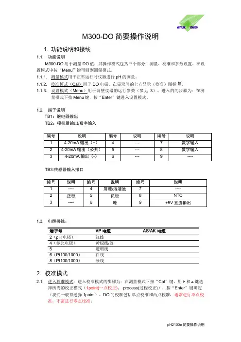
M300-DO简要操作说明1. 功能说明和接线1.1. 功能说明M300-DO用于测量DO值,其操作模式包括三个部分:测量、校准和参数设置。
在设置模式中按“Menu”键可回到测量模式。
1.1.1. 测量模式用于正常运行时仪器进行pH的测量。
1.1.2. 校准模式(Cal)用于DO电极。
在显示屏的上方显示(校准)图标。
1.1.3. 设置模式(Menu)用于调整仪器的运行参数(参见3)。
进入的的步骤为:在测量模式下按Menu键,按“Enter”键进入设置模式。
1.2. 端子说明TB1:继电器输出TB2:模拟量输出/数字输入TB3:传感器输入接口1.3. 电缆接线:端子号VP电缆AS/AK电缆2(pH电极)红线4(参比电极)黄绿线/蓝5 透明线6(Pt100/1000)白线8(Pt100/1000)绿线2. 校准模式2.1. 进入校准模式:进入校准模式的步骤为:在测量模式下按“Cal”键,用 和 键选择所需的校正模式(1point(一点校正); process(过程校正)),按“Enter”键确定(我们一般都选择1point)。
DO的校准包括单点校准和两点校准,通常进行单点校准,不需进行零点校准。
2.2. 校准介质:通常的校准介质为空气。
但在生化发酵过程中,由于探头在消毒后不能取出,校准介质为饱和介质,校准条件通常选择在实消后接种前,通最大量的饱和空气,搅拌速度开至最大。
2.3. 校准步骤:按Cal键出现 Calibration senor 然后按Enter ,出现Channel A OxygenO2 caliration 然后按Enter,出现 A Point1=100%sat 然后再出现Type =1point slope A o2=****%satO2 S=*****nA Z=0.000nA 按Enter 出现Calibration successful.Save Caliration Yes即校正完成注意:在校正的时候无法从此步骤中设定校正时候的压力,要通过Meun/Configure/Measurement/o2这个路径下输入校正压力和测量压力。
直读式电子比重计DH-300操作说明书请仔细阅读本说明书,以便正确使用。
请妥善保管本说明书,以备不时之需。
东莞市宏拓仪器有限公司-DahoMeter达宏美拓-服务热线:400 830 0646首次使用说明由于机器首次使用、运输、突然断电、重量损失等原因导致零点改变所引起按键无反应、显示OL 、不能正常显示0.00时,请按如下步骤操作,可排除上述现象。
在确定测量台和水中吊篮上的物品已经清空及水中吊篮与水槽没有接触的情况下: 1.关机。
2.长按【C 】键,再开机直至屏幕显示【CAL 】时方可放手。
3. 按【B 】键一次,显示数字【2】。
(如按【B 】键无反应,请重新尝试上述三个步骤,直至屏幕显示对应数字【2】为止)4. 按【A 】键一次 ,显示数字【1】。
5. 按【ZERO 】键一次,显示数字【3】。
6. 再按【ZERO 】键一次,显示数字【3】。
7. 按【C 】键一次,显示数字【5】。
8. 按【ENTER 】键一次,显示【CAL 】。
(若未显示【CAL 】请重复4-7四个步骤)9. 按【C】键一次,显示多位变化的数字。
10. 按【C】键一次,显示一位或者二位会跳动的数字。
11. 在测量台中央位置放上100g砝码。
12. 按【ENTER】键一次,显示【100】。
13. 再按【ENTER】键一次,显示【100.00】。
14. 取下砝码后,重新开机,即可解决上述现象,做正常校正后即可使用。
※注意:在关机前,请将测量台及吊篮中的物品取出。
(如测试样品、网球、抗浮架、玻璃杯等)。
DahoMeter达宏美拓-服务热线:400 830 0646目录1.概述 (5)1.1原理 (5)1.2用途 (5)2.规格参数 (5)3.仪器介绍 (6)3.1 仪器及配件清单说明 (6)3.2按键功能介绍 (7)3.3显示屏介绍 (7)4.安装 (8)4.1安装环境 (8)4.2防风罩安装 (8)4.3仪器安装 (8)5.校正方法 (9)6.其它设定 (9)6.1温度补偿 (9)6.2其它溶液比重值设定 (10)6.3水温密度对照表 (11)7.测试方法 (11)7.1样品重量参考 (11)7.2 固体测量(密度>1) (12)7.3 浮体测量(比重<1) (13)7.4 颗粒测量 (14)7.5测试结果的选择 (15)8.故障排除方法 (15)9.注意事项及保养 (16)9.1 使用前注意事项 (16)9.2 使用时注意事项 (16)9.3 特别注意事项 (16)1.概述1.1原理直读电子比重计DH-300是根据ASTM D297-93、D792-00、D618、D891等标准,采用阿基米德水中置换法原理与现代微电子技术相结合,以实际温度下水的密度为基础,经过两次重量测量分别得出待测样品的质量与体积,从而通过微电脑直接计算出样品之比重。
水管漏水探测仪使用说明书一、概述1.1主要用途及适用范围漏水探测仪是用于寻找并确定供水管道漏点位置的专用仪器,也可用于其它压力管道系统的检漏,当管道内流体在压力下溢出时,产生噪音能沿管道传播,或沿埋层介质传播到地面。
漏水检测仪能沿管线或其路面上方确定漏点位置。
水管漏水探测仪是采用低功耗微处理器和高级专用滤波器对噪声进行数字化处理的检漏仪器,它采用专门设计的宽带高灵敏度振动传感器(拾振器),将地面(或管道口)的噪声检拾并转换为电信号,经过相应放大并作数字化滤波处理,以两种显示图面在液晶显示屏上显示。
1.2产品特点1.2.1采用点阵式可加背光的液晶显示屏,以纵向7个光柱,在夜间方便观察。
1.2.2特设带宽两档变化,既照顾测听过程中振动能量分布的丰富性,又可在频率分析时更为精细。
1.2.3特设9个通道的存贮,既可分别将7频段信号也可将分别7个测点的测量值进行存储。
1.2.4设计的专用工程塑料机箱和相应面板操作均非常简洁明快,以方便简单的操作方式可取得明确广泛的信息,使检漏实测工作方便易行。
1.3产品规格参数表产品型号VICTOR528VICTOR538频率分析宽度70HZ~3000HZ范围,近5个倍频程,两种带宽70HZ~4000HZ范围,近5个倍频程,两种带宽频率分档(中心频率)a、100HZ b:200HZ c:400HZd:800HZ e:1KHZ f:1.5KHZg:2KHZ a、100HZ b:200HZ c:400HZ d:800HZ e:1KHZ f:1.5KHZg:3KHZ带宽a窄带:标示符号┃┃┃b、中宽带:标示符号┃┃┃┃┃数值显示在显示条上对应,取样值作最小值以0~100间相对量值显示屏幕尺寸160×160像素LCD显示窗二、产品整体结构2.1外形结构2.2产品附配件2.3液晶屏2.3.1全通/带通键:全通和带通模式的切换2.3.2带宽键:用于带宽的切换。
2.3.3设定键:用于时间、日期、背光亮度的设置。
e-mail:**************For latest product manuals: /en-us/pdf-manualsShop online at User’s GuideTHDP-10 SeriesTemperature/Humidity/Dew Point Meter2***********************Servicing North America:U.S.A. Omega Engineering, Inc.Headquarters: Toll-Free: 1-800-826-6342 (USA & Canada only)Customer Service: 1-800-622-2378 (USA & Canada only)Engineering Service: 1-800-872-9436 (USA & Canada only)Tel: (203) 359-1660Fax: (203) 359-7700 e-mail:e info@omFor Other Locations Visit /worldwideFEATURES1)Temperature measurement: Ambient Temp. Dew Point Temp. Wet Bulb Temp. (THDP-10),Heat index, WBGT temperature measurement (THDP-10-DL).2)Hold function: Freeze current readings on LCD.3)High/Low Temp. & RH alarm threshold setting.4)Function: Maximum, Minimum, Average and Recall.5)Auto power off function: Save power energy when not used.6)Temperature unit: Switchable.7)Battery low indicator.8)99 points manual recording (THDP-10).9)On line recording up to 64,000 points to PC (THDP-10-DL).10)Dimension: 160x60x40mm (Meter), Sensor tip (31mm)11)Power : AAA Volt battery x 3 pcsMATERIAL SUPPLIED1)Meter.2)User manual.3)USB cable. (THDP-10-DL).4)AAA batteries x 3 pcs.5)Plain box.6)Free software download from website. (THDP-10-DL).SPECIFICATIONKEYPAD (CONTROLS)PWR: Turn on or off, bell icon (audible alarm function) activates/inactive.HOLD: Freeze current readings. Forward review or Increase digit.BKLT: Back review or decrease digit.MAX/MIN: Review Max. Min. AVG readings and move to right digit in alarm threshold setting.MODE: Toggle Temp. DP, WB (THDP-10), WBGT, HI (THDP-10-DL) mode. Move to left digit in alarm threshold setting.Long press to review memorized recording. (THDP-10).SET: Long press to enter Hi, Lo alarm threshold setting.Under Hi and Lo alarm setting mode, short press to toggle Temp. or RH setting mode.Long press to save current temp. and humidity readings.UNIT: Toggle Temperature unit ℃and℉. Under Hi and Lo alarm setting mode, short press to toggle HI or LO setting mode.LCD FULL DISPLAYOPERATION(1) POWER ON/OFFShort press” PWR” button to turn on the meter, press and hold for 2 seconds to turn off the meter.(2) MAX/MIN/AVGShort press MAX/MIN button to cycle display Maximum, Minimum, Average readings of Temperature and RH since powered on.(3) CHANGE DEGREE ℃/℉Short press UNIT button to switch ℃ and ℉.(4) DP/WB/HI/WBGTShort press MODE button to toggle current temperature, DP (Dew point), WB (Wet bulb temperate) (THDP-10), HI (Heat index), WBGT(THDP-10-DL) at the second layer.(5) FREEZE READINGShort press “HOLD” button under normal measurement, “HLD” icon shows on screen to freeze current readings.(6) DISABLE AUTO-POWER OFFMeter will turn off automatically in 20 minutes when no use, to disable auto power off function, when meter power off, press HOLD+PWR, LCD shows “n”, the auto power-off function is disabled.(7) TURN ON/OFF ALARM FUNCTIONTAfter setting up the threshold, short press PWR button, the bell icon shows on screen for alarm is activated. Short press PWR button again to disable alarm function.When it is under low power, the low battery icon shows on the screen, recommend to replace with new battery.(8) HI. LO ALARM SETTINGHigh, Low alarm threshold function:( Meter is default Hi RH%: 70% , Lo RH%: 20%, Hi Temp.: 40℃ ,Lo temp: 10℃)1. Press and hold SET button for 2 seconds, enter Temperature alarm setting.First set up high temperature alarm, screen shows “SET HI”, the last digit ( decimal digit) at second layer is flashing, short press HOLD button to increase, BKLT to decrease, select to left digit by pressing MODE(←) and to right digit by pressing MAX/MIN(→).The last digit is flashing again for change selection.SET button to toggle RH% or Temp. values setting, the last digit of RH% or temp. is2. Short pressflashing for changing digit.3.Short press UNIT button to enter LO alarm setting, follow the same step as you set for temperature.4.Press and hold SET button to save and back to normal measurement mode.(9)RECORD 99 POINTS (THDP-10 only)Short press SET button to save current readings (temp. and humidity), REC icon shows next to RH% readings and record number shows next to temperature readings about 2 seconds then disappear. Meter may store up to 99 points.Recall recorded data: long pressing MODE button to review memorized recording, keep pressing HOLD button to review next data, press BKLT button to view the reading from back number.Long pressing MODE button again to return measurement mode.CLEAR MEMORY:Under 99 points history recording mode, long pressing SET button to clear the memory.(10)USB ON LINE LOGGING FUNCTION (THDP-10-DL only)1.Download free software from website.2.Install USB driver (Step1)3.Install MIC online logging software(Step2)4.Plug supplied USB cable onto meter first, turn on the software, PC automatically detect COMM port toUSB.5.Now meter’s readings on line upload to PC software, you may select sample rate from 5 secs ,10secs ,15 secs…. up to 6 hours, and maximum record point up to 64,000 points.Data can be saved as .txt or csv. format for further analysis.ON LINE DATALOGGING PC SOFTWARE SCREENPlease install USB driver and Datalogger software in your computer, once USB connects with meter and PC, meter automatically detects correct COM port and meter real time transmits data to PC screen, you will see some dots on the screen, more dots, more clear to see a curve. After recording for a while, you can see clear curve as below:(1)Logger setting:Locked: no functionSample rate:Selectable from 5 seconds to 6 hoursPress OK to start recording(2) Save Data (txt. Format)Save data: Press File in tool bar, then click Save File to save data in designated folder or press Floppy icon to save data.Or(3) Open File(4) View Data TableSave Data Table: Select View to save Data Table as Excel file. A pop-window will show once you press Data Table (Excel).File is saved as txt. format Red line is timeline, you can move it tosee the readings in recorded timesThe reading keeps updating while you still in excel status. If you don’t close excel after you save the file, the reading also updating automatically.(5) Data Table (Excel)NOTE: Select temperature unit ℃℉ before start online recording function. During recording, DO NOT press UNIT button. The software records the current temperature unit which shows on LCD.WARRANTYThis instrument is warranted for two years from the date of purchase (One year limited warranty applies to cables). A Return Authorization letter must be issued before returning for any reason. This warranty does not apply to defects resulting from action of the user such as misuse, abuse, alteration neglect, improper wiring, improper maintenance or repair, or unauthorized modification, damage resulting from leaking batteries, operation outside of specification.During the warranty period the manufacturer reserved the right to decide either to repair or replace the product. The meters are to be returned along with good packing to prevent any damage in shipment and insured against possible damage or loss.The two year’s warranty doesn’t apply to:⚫ Accessories and batteries (not covered by warranty)⚫ Claim is not acceptable for improper use (including adaptation to particular applications not foreseen in the instructions manual) or improper combination with incompatible accessories or equipment or by previous attempts for repair carried out by none skilled or unauthorized personnel.⚫Sensor damaged by user improper use; watering, burning, condensation....Saved file Blank part is interval of the saved file and notNot saved file(Keep updating)OMEGA’s policy is to make running changes, not model changes, whenever an improvement is possible. This affords our customers the latest in technology and engineering.OMEGA is a trademark of OMEGA ENGINEERING, INC.© Copyright 2018 OMEGA ENGINEERING, INC. All rights reserved. This documen t may n ot be copied, photocopied, FOR WARRANTY RETURNS, please have thefollowing information available BEFORE contacting OMEGA:1. P urchase Order number under which the product was PURCHASED,2. M odel and serial number of the product under warranty, and3. Repair instructions and/or specific problemsrelative to the product.FOR NON-WARRANTY REPAIRS, consult OMEGA for current repair charges. Have the following information available BEFORE contacting OMEGA:1.Purchase Order n umber to cover the COST of the repair,2. Model and serial number of the product, and3. Repair instructions and/or specific problemsrelative to the product.RETURN REQUESTS/INQUIRIESDirect all warran ty an d repair requests/in quiries to the OMEGA Customer Service Departmen t. BEFORE RETURNING ANY PRODUCT(S) TO OMEGA, PURCHASER MUST OBTAIN AN AUTHORIZED RETURN (AR) NUMBER FROM OMEGA’S CUSTOMER SERVICE DEPARTMENT (IN ORDER TO AVOID PROCESSING DELAYS). The assigned AR number should then be marked on the outside of the return package and on any correspondence.The purchaser is responsible for shipping charges, freight, insurance and proper packaging to prevent breakage in transit.WARRANTY/DISCLAIMEROMEGA ENGINEERING, INC. warran ts this un it to be free of defects in materials an d workman ship for a period of 25 months from date of purchase. OMEGA’s WARRANTY adds an additional one (1) month grace period to the normal (2) year product warranty to cover handling and shipping time. This ensures that OMEGA’s customers receive maximum coverage on each product.If the unit malfunctions, it must be returned to the factory for evaluation. OMEGA’s Customer Service Department will issue an Authorized Return (AR) number immediately upon phone or written request. Upon examination by OMEGA, if the unit is found to be defective, it will be repaired or replaced at no charge. OMEGA’s WARRANTY does not apply to defects resulting from any action of the purchaser, in cludin g but n ot limited to mishan dlin g, improper in terfacin g, operation outside of design limits, improper repair, or unauthorized modification. This WARRANTY is VOID if the unit shows evidence ofhavin g been tampered with or shows eviden ce of havin g been damaged as a result of excessive corrosion ; or curren t, heat, moisture or vibration ; improper specification ; misapplication ; misuse or other operatin g con dition s outside of OMEGA’s con trol. Compon en ts in which wear is n ot warran ted, in clude but are n ot limited to contact points, fuses, and triacs.OMEGA is pleased to offer suggestions on the use of its various products. However,OMEGA neither assumes responsibility for any omissions or errors nor assumes liability for any damages that result from the use of its products in accordance with information provided by OMEGA, either verbal or written. OMEGA warrants only that the parts manufactured by it will be as specified and free of defects. OMEGA MAKES NO OTHER WARRANTIES OR REPRESENTATIONS OF ANY KIND WHATSOEVER, EXPRESS OR IMPLIED, EXCEPT THAT OF TITLE, AND ALL IMPLIED WARRANTIES INCLU DING ANY WARRANTY OF MERCHANTABILITY AND FITNESS FOR A PARTICU LAR PU RPOSE ARE HEREBY DISCLAIMED. LIMITATION OF LIABILITY: The remedies of purchaser set forth herein are exclusive, and the total liability of OMEGA with respect to this order, whether based on contract, warranty, negligence, indemnification, strict liability or otherwise, shall not exceed the purchase price of the component upon which liabilityis based. In no event shall OMEGA be liable for consequential, incidental or special damages.CONDITIONS: Equipmen t sold by OMEGA is n ot in ten ded to be used, n or shall it be used: (1) as a “Basic Component” under 10 CFR 21 (NRC), used in or with any nuclear installation or activity; or (2) in medical application s or used on human s. Should an y Product(s) be used in or with an y n uclear installation or activity, medical application, used on humans, or misused in any way, OMEGA assumes n o respon sibility as set forth in our basic WARRANTY / DISCLAIMER lan guage, an d, addition ally, purchaser will indemnify OMEGA and hold OMEGA harmless from any liability or damage whatsoeverarising out of the use of the Product(s) in such a manner.。
目录第一部分:基本概述 (3)基本描述 (3)液位变送器 (3)与磁耦合液位指示器配套使用 (4)直接插入式 (4)第二部分:概述 (5)变送器详细描述 (5)工作原理 (5)第三部分:安装和接线 (6)与磁耦合液位指示器配套安装 (6)直接插入式 (7)单回路接线(两线制) (7)第四部分:技术规格 (7)变送器电气规格 (7)变送器探杆 (8)第五部分:标定 (8)LTM-200D/300输出标定 (8)LTM-200D/300 LED操作菜单 (9)第六部分:问题解答 (11)通过HART协议诊断 (11)标定问题 (11)磁干扰 (11)电源故障问题 (11)变送器开机启动 (12)第七部分:液位计的现场隔热 (13)现场隔热 (13)第八部分:保质期 (14)ISE/Magtech保质期 (14)第九部分:产品常见故障的维护 (15)常见故障和解决方案 (15)第一部分:基本概述1.0 基本描述LTM-200D/LTM-300磁致伸缩液位计是一种电子式现场工业仪表,适合应用于要求防爆(Ex ia ⅡCT4)和不要求防爆的工业领域,经过多年的现场应用,不同地方不同行业的用户均证实该产品测量稳定,使用方便。
LTM-200D/LTM-300磁致伸缩液位计系列是一种双回路供电的轻巧型产品,可以同时测量和传输三个变量:总液位、界位和温度,输出2个4~20mA模拟量信号。
其中可选择的温度信号输出是通过HART协议实现。
LTM-200D/LTM-300其他可选特征包括:●第二套界位数据输出(需要不同密度的第二套浮子测量)。
●多种探杆材质可选。
●高稳定性和高精确度Magtech产品序列号每个产品都有独立的生产序列号,头两位显示生产月份,后面两位是年份。
比如,产品序列号0606/1234是2006年6月生产,产品自身序号为1234。
1.1 液位变送器LTM-200D/LTM-300磁致伸缩液位计结构简单,测量时,浮子随着液位的上升或下降而上升或下降。
三鼎电子经纬仪说明书前言尊敬的用户:欢迎你购买和使用北京三鼎光电仪器有限公司的产品,向你对本公司产品的信任表示衷心的感谢~本公司自成立以来,一直把振兴测绘民族工业为己任,把生产具有国际先进水平的测绘仪器系列产品作为自身的奋斗目标。
本公司生产的测绘仪器外形美观,性能可靠,功能齐备。
使用仪器前请您提前仔细阅读本操作手册。
本公司生产的系列测绘仪器由科立达测绘仪器有限公司总代理销售。
您在使用仪器过程中如发现的问题或提出建议,请就近向销售网点反映,我们将竭诚为您服务并表示衷心感谢。
(为保持仪器的良好工作状态,建议您每年在销售网点进行一次专业的仪器保养。
)北京三鼎光电仪器有限公司二零零七年三月厂家保留对技术及产品规格进行修改的权利而不事先通知。
?I?目录(特点 ..................................................................... ........................................................................ .............. 1 12(预备事项 ..................................................................... ........................................................................ (1)2.1.预防事项 ..................................................................... .. (1)2.2.部件名称 ..................................................................... .. (2)2.3.仪器开箱和存放 ..................................................................... .. (2)2.4.电池的装卸、信息和充电 ..................................................................... . (3)2.5.仪器与机座的装卸 ..................................................................... .................................................... 4 3(键盘功能与信息显示 ..................................................................... . (5)3.1.键盘符号与功能 ..................................................................... .. (5)3.2.操作面板与操作键 ..................................................................... .................................................... 5 4(初始设置 ..................................................................... ........................................................................ (6)4.1.设置项目 ..................................................................... .. (7)4.2.设置方法 ..................................................................... .. (7)5(测量准备 ..................................................................... ........................................................................ (9)5.1.仪器的安置、对中和整平 ..................................................................... . (9)5.2.望远镜目镜调整和目标照准 ..................................................................... . (10)5.3.打开或关闭电源 ..................................................................... (10)5.4.指示竖盘指标归零(垂直置零) .................................................................... ....................... 11 6(基本测量 ..................................................................... ........................................................................ . (11)6.1.盘左/盘右观测 ..................................................................... .. (11)”(置零) .................................................................... ........................................... 12 6.2.水平角置“06.3.水平角与竖直角测量 ..................................................................... . (12)6.4.水平角锁定与解除(锁定) .................................................................... .. (12)6.5.水平角象限鸣响设置 ..................................................................... . (13)6.6.竖直角的零方向设置 ..................................................................... . (13)6.7.天顶距与垂直角的测量 ..................................................................... (13)6.8.斜率百分比 ..................................................................... .. (14)6.9.重复角度测量 ..................................................................... . (14)6.10.角度输出功能 ..................................................................... .. (15)6.11.角度存储功能 ..................................................................... .. (15)6.12.望远镜测距丝测距 ..................................................................... ................................................ 16 7(内存功能 ..................................................................... ........................................................................ . (16)7.1.查看仪器电子序列号 ..................................................................... . (16)7.2.查看内存角度数据 ..................................................................... .. (16)7.3.清除内存角度数据 ..................................................................... .. (17)7.4.向串口发送内存数据 ..................................................................... .............................................. 17 8(电子手薄连接 ..................................................................... .. (17)9(检验与校正 ..................................................................... ........................................................................189.1.长水准器 ..................................................................... (18)9.2.圆水准器 ..................................................................... (18)9.3.望远镜分划板倾斜 ..................................................................... .. (18)9.4.视准轴与横轴的垂直度(2C) ................................................................... .. (19)?II?9.5.竖盘指标零点自动补偿 ..................................................................... (19)9.6.竖盘指标差(i角)和竖盘指标零点设置 ..................................................................... .. (19)9.7.光学对中器 ..................................................................... .. (20)9.8.其他调整 ..................................................................... (21)10(技术指标 ............................................................................................................................................. .. 2211(错误代码信息表 ..................................................................... .. (24)12(附件...................................................................... ........................................................................ (25)?III?1(特点北京三鼎光电仪器有限公司生产的DT系列电子经纬仪,结构合理、美观大方、功能齐全、性能可靠、操作简单、易学易用,很容易实现仪器的所有功能,而且还具备如下特点:可与电子记录手簿联接可与科立达测绘仪器有限公司生产的电子记录手簿联机,完成野外数据的自动采集。