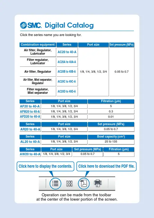
SMC(中国)有限公司--产品样本电子版
- 格式:pdf
- 大小:455.98 KB
- 文档页数:1
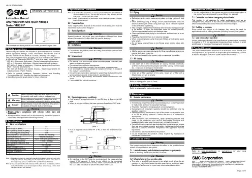
VR12F-TF222-005ENPage 1 of 1Instruction ManualAND Valve with One-touch FittingsThe intended use of this product is to control pneumatic signal lines.These safety instructions are intended to prevent hazardous situations and/or equipment damage. These instructions indicate the level of potential hazard with the labels of “Caution,” “Warning” or “Danger.” They are all important notes for safety and must be followed in addition to International Standards (ISO/IEC) *1), and other safety regulations. *1)ISO 4414: Pneumatic fluid power - General rules relating to systems. ISO 4413: Hydraulic fluid power - General rules relating to systems.IEC 60204-1: Safety of machinery - Electrical equipment of machines. (Part 1: General requirements)ISO 10218-1: Robots and robotic devices - Safety requirements for industrial robots - Part 1: Robots.• Refer to product catalogue, Operation Manual and Handling Precautions for SMC Products for additional information. • Keep this manual in a safe place for future reference.Warning • Always ensure compliance with relevant safety laws and standards.• All work must be carried out in a safe manner by a qualified person in compliance with applicable national regulations.2 SpecificationsNote 1) Use caution when the maximum operating pressure is used with soft nylonand polyurethane. Depending on the temperature, these tubes have a lower operating pressure. Refer to the specification of the tubes.Note 2) Two axes (horizontal and vertical) and two directions were tested, and nomalfunction of the valve occurred (pulse shape: sine shape), 3 times (test sample mounted with bracket).Note 3) No malfunction occurred in a sweep cycle test between 10 to 150 Hz atvibration sweep 0.35 mm. The test was performed in the two axes and two directions, 7 min per cycle (20 cycles).Note 4) Brass components are all electroless nickel plated as standard. (Copper-free and fluorine-free)2.2 Response timeValve response time depends on the overall circuit design, so it must be determined by the circuit designer. 2.3 Special productsWarningSpecial products (-X) might have specifications different from those shown in this section. Contact SMC for specific drawings.3 Installation3.1 InstallationWarning• Do not install the product unless the safety instructions have been read and understood. 3.2 EnvironmentWarning• Do not use in an environment where corrosive gases, chemicals, salt water or steam are present.• Do not use in an explosive atmosphere.• Do not expose to direct sunlight. Use a suitable protective cover.• Do not install in a location subject to vibration or impact in excess of the product’s specifications.• Do not mount in a location exposed to radiant heat that would result in temperatures in excess of the product’s specifications.• Do not use in high humidity environment where condensation can occur.• Contact SMC for altitude limitations.3.3 Operating pressure conditions• Only when air is supplied to both P1 and P2 does air flow to the OUT side.• When air pressure differs, the lower pressure flows to the OUT side.Figure 1.• If air is supplied only to either P1 or P2, it does not flow to the OUT side.Figure 2.Warning• Air may flow to the OUT side for a moment until the valve switches (About 1/100 second). If there is any effect on the connected equipment due to the above air flow, install a speed controller, etc, on the OUT side, and adjust to prevent this effect before use.3.4 PipingCaution• Before connecting piping make sure to clean up chips, cutting oil, dust etc.• When installing piping or fittings, ensure sealant material does not enter inside the port. When using seal tape, leave 1 thread exposed on the end of the pipe/fitting.• Stop using the equipment immediately when air leaks are large enough to be audible, or when the equipment does not operate properly. Perform appropriate function and leakage tests.• Check periodically that piping is not loosened and that there is no air leakage.• Regularly check that there is no external damage.• When connecting tubes using One-touch fittings, provide some spare tube length.• Do not apply external force to the fittings when binding tubes with bands.Caution• SMC products have been lubricated for life at manufacture, and do not require lubrication in service.• If a lubricant is used in the system, refer to catalogue for details. 3.5 Air supplyWarning• Use clean air. If the compressed air supply includes chemicals, synthetic materials (including organic solvents), salinity, corrosive gas etc., it can lead to damage or malfunction.Caution• Install an air filter upstream of the valve. Select an air filter with a filtration size of 5 μm or smaller.4 How to OrderRefer to catalogue for ‘How to Order’.5 Outline DimensionsRefer to catalogue for outline dimensions.6 Maintenance6.1 General maintenanceCaution• Not following proper maintenance procedures could cause the product to malfunction and lead to equipment damage.• If handled improperly, compressed air can be dangerous.• Maintenance of pneumatic systems should be performed only by qualified personnel.• Before performing maintenance, turn off the power supply and be sure to cut off the supply pressure. Confirm that the air is released to atmosphere.• After installation and maintenance, apply operating pressure and power to the equipment and perform appropriate functional and leakage tests to make sure the equipment is installed correctly.• If any electrical connections are disturbed during maintenance, ensure they are reconnected correctly, and safety checks are carried out as required to ensure continued compliance with applicable national regulations.• Do not make any modification to the product.• Do not disassemble the product, unless required by installation or maintenance instructions.7 Limitations of UseWarningThe system designer should determine the effect of the possible failure modes of the product on the system.7.1 Limited warranty and disclaimer/compliance requirements Refer to Handling Precautions for SMC Products.Warning7.2 Effect of energy loss on valve state• The valve is an AND logic element in an all-air circuit. When the air pressure is cut to both inputs the valve goes into an undefined state. Backflow of air from out to in port may occur under this condition.• It is the responsibility of the system designer to determine the effect in the system when air pressure is cut and when it is restored. 7.3 Cannot be used as an emergency shut-off valveThis product is not designed for safety applications such as an emergency shut-off valve. If the valves are used in this type of system, other reliable safety assurance measures should be adopted.7.4 Holding of pressureSince valves are subject to air leakage, they cannot be used for applications such as holding pressure (including vacuum) in a system.Caution7.5 Low temperature operationUnless otherwise indicated in the specifications for each valve, operation is possible to -5˚C, but appropriate m easures should be taken to avoid solidification or freezing of drainage and moisture, etc.8 Product DisposalThis product shall not be disposed of as municipal waste. Check your local regulations and guidelines to dispose this product correctly, in order to reduce the impact on human health and the environment.9 ContactsRefer to or www.smc.eu for your local distributor/importer.URL : https:// (Global) https:// www.smc.eu (Europe) SMC Corporation, 4-14-1, Sotokanda, Chiyoda-ku, Tokyo 101-0021, JapanSpecifications are subject to change without prior notice from the manufacturer. © 2022 SMC Corporation All Rights Reserved. Template DKP50047-F-085MORIGINAL INSTRUCTIONS2 (OUT)(IN) 1 (IN) 1IN P 1 IN P 2 OUT OUTOUT IN P 1 IN P 2 IN P 1 IN P 2。
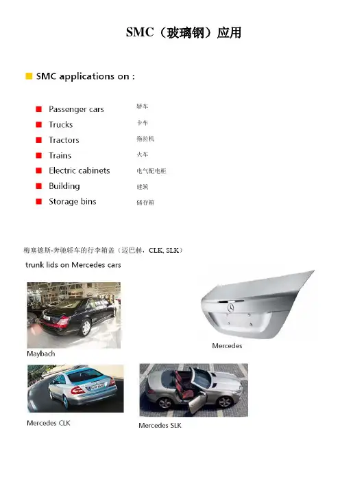
SMC(玻璃钢)应用
-轿车
-卡车
-拖拉机
-火车
-电气配电柜
-建筑
-储存箱
梅塞德斯-奔驰轿车的行李箱盖(迈巴赫,CLK, SLK)
新大众Cabriolet行李箱盖
内衬
外壳
尾门和前舱盖
扰流板(宝马3系)
各种卡车上的SMC制件
-保险杠
-导流板
-门构件
-前面板
-翼子板
-侧围罩
-脚踏板
-内饰件
驾驶操控台
油箱
SMC前面板和前保险杠
-拖拉机车顶板
-内壳
-外壳
-功能集成块
-折合顶
-彩色SMC
高速列车车头
窗框
SMC柱子外立面
新型高速列车(TGV)窗框
圆盘卫星接收器
电话亭
厨房水盆
浴缸
整体浴室
灯箱
电器配电柜
具备阻燃性的SMC储藏箱
库房着火时的情景(SMC材料不燃)火源熄灭后的SMC储藏箱。
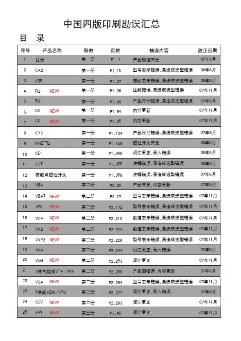
SMC(中国)有限公司
佚名
【期刊名称】《电子工业专用设备》
【年(卷),期】2007(36)5
【摘要】SMC-世界最大的气动元件制造商之一,销售网络及生产基地遍布世界各地。
SMC气动元件的种类超过10100种,规格达到590000个之多。
【总页数】2页(P80-81)
【正文语种】中文
【中图分类】F326.13
【相关文献】
1.SMC点燃产业升级的“圣火”——访SMC(中国)有限公司总经理赵彤先生[J], 杨晓玉
2.SMC倡导绿色工业产品——访SMC(中国)有限公司总经理赵彤先生 [J],
3.战略重塑续写传奇访SMC投资管理有限公司、SMC自动化有限公司总经理马
清海 [J], 佟伟
4.促进世界工业自动化发展的SMC——访SMC中国有限公司总经理赵彤先生 [J], 魏莹
5.走近SMC,解读SMC——SMC(中国)有限公司赵彤总经理访谈纪要 [J], 栗延文;王天谌;魏莹;樊有海
因版权原因,仅展示原文概要,查看原文内容请购买。
FEA TURES* Glass passivated junction* 1500 Watts Peak Pulse Power capability on 10/1000 µs waveform* Excellent clamping capability * Low zener impedance * Fast response timeMECHANICAL DATA*Case: Molded plastic*Epoxy: UL 94V-0 rate flame retardant*Lead: MIL-STD-202E, Method 208 guaranteed* Polarity: Color band denotes positive end (cathode) except bidirectional types *Mounting position: Any *Weight: 0.21 gramTECHNICAL SPECIFICATIONS OF TRANSIENT VOLTAGE SUPPRESSOR VOLTAGE RANGE - 5.0 to 220Volts PEAK PULSE POWER - 1500 Watts Peak Pulse Power Dissipation on 10/1000 µs waveform (Note1,FIG.1)Steady State Power Dissipation at T = 75C Lead Lengths .375"(9.5mm) (Note 2)Peak Forward Surge Current, 8.3ms single half sine-wave superimposed on rated load(JEDEC Method) (Note 3)Operating and Storage T emperature RangeSYMBOLP PPMP M(AV)I FSM T J , T STGV ALUE Minimum 15005.0100-55 to + 175UNITS WattsWattsCAmpsNOTES : 1. Non-repetitive current pulse, per Fig.3 and derated above TA = 25C per Fig. 2.2. Mounted on Copper Leaf area of 0.31 X 0.31"( 8.0 X 8.0mm ) per Fig. 53. 8.3ms single half sine-wave or equivalent square wave, duty cycle = 4 pulses per minute maximum.DEVICES FOR BIPOLAR APPLICA TIONSFor Bidirectional use C or CA suffix (e.g. SMCJ5.0C, SMCJ220CA).Electrical characteristics apply in both directionsRatings at 25C ambient temperature unless otherwise specified.Single phase, half wave, 60 Hz, resistive or inductive load,For capacitive load, derate current by 20%.MAXIMUM RATINGS AND ELECTRICAL CHARACTERISTICSRATING AND CHARACTERISTIC CURVES (SMCJ5.0 THRU SMCJ220CA)P E A K P U L S E P O W E R (P P P ) O R C U R R E N T (I P P ) D E R A T I N G I N P E R C E N T A G E , %0T A , AMBIENT TEMPERATURE, (C)FIG. 2 - PULSE DERATING CURVE255075100255075100125150175200FIG. 3 - PULSE WAVEFORM1.02.03.04.0t, TIME, mS101005000C J , C A P A C I T A N C E , p FFIG. 4 - TYPICAL JUNCTION CAPACITANCE1.010100200V (BR), BREAKDOWN VOLTAGE, VOLTS100FIG. 5 - MAXIMUM NON-REPETITIVE FORWARDSURGE CURRENT UNIDIRECTIONALI F S M , P E A K F O R W A R D S U R G E C U R R E N T A M P E R E S8.3ms Single Half Sine-Wave (JEDEC Method)NUMBER OF CYCLES AT 60 Hz1101000FIG. 1 - PEAK PULSE POWER RATING CURVENon-Repetitive Pulse Waveform Shown in Fig.3T A = 25C0.11.0101000.1µS1.0µS10µS100µS1.0mS10mSP P M , P E A K P U L S E P O W E R , k WT P , PULSE WIDTH, sec0.31X0.31”(8.0X8.0mm)copper pad areas1000020000200DisclaimerDC COMPONENTS CO., LTD.Any Customer or user of this document or products described herein in such applications shall assume all risks of such use and will agree to hold DC COMPONENTS are harmless against all damages.DC COMPONENTS disclaims any and all liability arising out of the application or use of any product, including consequential or incidental damages. Statement regarding the suitability of products for certain typesof applications are based on DC COMPONENTS ’s knowledge of typical requirements that are often placed on DC COMPONENTS products in generic applications. Such statements are not binding statements about the suitability of products for aparticular application. It is the customer's responsibility to validate that aparticular product with the properties described in the product specification is suitable for use in a particular application.DC COMPONENTS reserve the right to make modifications, enhancements, improvements, corrections or other changes without further notice to this document and any product described herein, and disclaim any and all liability for any errors, inaccuracies or incompleteness contained in any datasheet or in any other disclosure relating to any product. Parameters provided in datasheets and specifications may vary in different applications and performance may vary over time. All operating parameters, including typical parameters, must be validated for each customer application by the customer’s technical experts.Product specifications do not expand or otherwise modify DC COMPONENTS ’s terms and conditions of purchase, including but not limited to the warranty expressed therein.Unless otherwise in writing, DC COMPONENTS products are intended for use as general electronic components in standard applications ( eg: Consumer electronic, Computer equipment, Office equipment, etc.), and not recommended for use in a high specific application where a failure or malfunction of the device could result in human injury or death ( eg: Aerospace equipment, Submarine cables, Combustion equipment, Safety devices, Life support systems, etc.)Customers using or selling DC COMPONENTS products not expressly indicated for use in such applications do so at their own risk. If customer intended to use DC COMPONENTS standard quality grade devices for applications not envisioned by DC COMPONENTS , please contact our sales representatives in advance.。
Other SettingsSummary of Product partsSimple Setting ModeTroubleshootingNote: Specifications are subject to change without prior notice and any obligation on the part of the manufacturer.© 2020 SMC Corporation All Rights ReservedAkihabara UDX 15F, 4-14-1, Sotokanda, Chiyoda-ku, Tokyo 101-0021, JAPANPhone: +81 3-5207-8249 Fax: +81 3-5298-5362URL https://Specifications/Outline with DimensionsRefer to the product catalog or SMC website (URL https://) for moreinformation about the product specifications and outline dimensions.PS※※-OMX0003 DC(+)OUT1NCNCDC(-)BrownBlackWhiteGrayBlueDefault settingsWhen the pressure exceeds the setvalue, the switch will be turned on.When the pressure falls below theset value by the amount ofhysteresis or more, the switch willbe turned off. The default setting isto turn on the pressure switch whenthe pressure reaches the centre ofthe atmospheric pressure and upper limit of the rated pressure range. If this condition,shown to the right, is acceptable, then keep these settings.Error indication functionThis function is to display error location and content when a problem or error has occurred.above are displayed, please contact SMC.Refer to the SMC website (URL https://) for more information abouttroubleshooting.button between3 and 5 sec.∗:The outputs will continue to operate during setting.∗:If a button operation is not performed for 3 seconds during the setting, the display will flash.(This is to prevent the setting from remaining incomplete if, for instance, an operator were to leave duringsetting.)∗:3 step setting mode, simple setting mode and function selection mode settings are reflected each other.[3 step setting mode (hysteresis mode)]orcan be changed in the same way.button once when the item to beThe set value on the sub display (right) will startflashing.orbutton and can be reduced with button.buttons are pressed and held simultaneously for 1 second orlonger, the set value is displayed as [- - -], and the set value will be the same as thecurrent pressure value automatically (snap shot function).Afterwards, it is possible to adjust the value by pressing button.button to complete the setting.The pressure switch turns on within a set pressure range (from P1L to P1H) duringwindow comparator mode.Set P1L, the lower limit of the switch operation, and P1H, the upper limit of the switchoperation and WH1 (hysteresis) following the instructions given above.(When reversed output is selected, the sub display (left) shows [n1L] and [n1H].)∗:Set OUT2 in the same way. (ex. P_2, H_2)∗:Setting of the normal/reverse output switching and hysteresis/window comparator mode switchingare performed with the function selection mode [F 1] OUT1 setting and [F 2] OUT2 setting.value[F 0] Display units, switch output specificationsand diagnostic information selection functionPeak/bottom value indicationThe value can be displayed on the sub display by pressing button inmeasurement mode.Snap shot functionbuttons for 1 secondor longer simultaneously. Then, the set value of the sub display (right) shows [- - -], andthe values corresponding to the current pressure values are automatically displayed.Zero-clear functionIn measurement mode, when the buttons are pressed for 1 second orlonger simultaneously, the main display shows [- - -], and the reset to zero.The display returns to measurement mode automatically.Key-lock functionTo set each of these functions, refer to the SMC website(URL https://) for more detailed information, or contact SMC.button between 1 and 3 seconds in measurementmode. [SEt] is displayed on the main display. When the button is releasedwhile in the [SEt] display, the current pressure value is displayed on themain display, [P_1] or [n_1] is displayed on the sub display (left), and theset value is displayed on the sub display (right) (Flashing).or button to(The snap shot function can be used.)or button to set the(The snap shot function can be used.)or button, the delay time of the switch output can be selected.button for 2 seconds or longer to complete the setting.∗:If the button is pressed for less than 2 seconds, the setting will moves to the OUT2 setting.In the window comparator mode, set P1L, the lower limit of the switch operation, andP1H, the upper limit of the switch operation, WH1 (hysteresis) and dt1 (delay time)following the instructions given above.(When reversed output is selected, the sub display (left) shows [n1L] and [n1H].)∗:Set OUT2 in the same way.Function selection modebuttonbetween 3 and 5 seconds, to display [F 0].Select to display the function to be changed[F button for 2seconds or longer in function selection modeto return to measurement mode.∗:Some products do not have all the functions. If no functionis available or selected due to configuration of otherfunctions, [- - -] is displayed on the sub display (right).Names of individual partsPressure Setting3 Step Setting Mode(URL https://) for more detailed information, or contact SMC.MaintenanceHow to reset the product after a power cut or forcible de-energizingThe setting of the product will be retained as it was before a power cut or de-energizing.The output condition is also basically recovered to that before a power cut or de-energizing, but may change depending on the operating environment. Therefore, checkthe safety of the whole installation before operating the product. If the installation is usingaccurate control, wait until the product has warmed up (approximately 10 to 15 minutes). Safety InstructionsBefore UseDigital Pressure SwitchZSE20C(F)-L/ISE20C(H)-LThank you for purchasing an SMC ZSE20C(F)-L/ISE20C(H)-L Series Digital PressureSwitch.Please read this manual carefully before operating the product and make sure youunderstand its capabilities and limitations. Please keep this manual handy for futurereference.Safety InstructionsThese safety instructions are intended to prevent hazardous situations and/orequipment damage.These instructions indicate the level of potential hazard with the labels of "Caution","Warning" or "Danger". They are all important notes for safety and must be followed inaddition to International standards (ISO/IEC) and other safety regulations.OperatorSwitch ONAt normal output Switch OFFSet valueP_1HysteresisH_1TimePressureDefault settingThe default setting is as follows.If no problem is caused by this setting,keep these settings.[F 1] Setting of OUT1[F 2] Setting of OUT2Same setting as [F 1] OUT1.InstallationMountingMount the optional bracket and panel mount adapter to the pressure switch.When the pressure switch is to be mounted in a place where water and dustsplashes occur, insert a tube into the air-relieving port of the pressure switch.(Refer to "Tube attachment")Mounting with bracketMount the bracket to the body with mounting screws(Self tapping screws), then set the body to the specified position.∗: Tighten the bracket mounting screws to a torque of 0.5±0.05 Nm.Self tapping screws are used, and should not be re-used several times.∗•Bracket A (Part No.: ZS-46-A1)•Bracket C (Part No.: ZS-46-E)<Rear piping><Bottom piping>WiringWiring connectionsConnections should be made with the power supply turned off.Use a separate route for the product wiring and any power or high voltage wiring.Otherwise, malfunction may result due to noise.If a commercially available switching power supply is used, be sure to ground theframe ground (FG) terminal. If the switching power supply is connected for use,switching noise will be superimposed and it will not be able to meet the productspecifications. In that case, insert a noise filter such as a line noise filter/ferritebetween the switching power supplies or change the switching power supply toHow to use connectorConnection using screw type fittingConnect suitable piping to the port.To connect the hexagon socket head plug or fitting to thepressure port, hold the hexagon part of the pressure port with asuitable spanner. Apply atightening torque of 8 to12 Nm.When tightening, do nothold the pressure switchbody with a spanner.Tube attachmentWhen this pressure switch is used in a place where water and dust splashes mayoccur, insert a tube in the air-opposite side up to the safe positionto keep it from water and dust.(See the right figure.)∗: The tube should be inserted to the end ofthe air-relieving port.∗: SMC TU0425 (polyurethane, O.D ø4, I.Dø2.5) is a suitable tubing.To the safe position to keep from water and dust。
SMC外壳产品状态报告一、SMC片状模塑料SMC是“Sheet Molding Compound”的英文缩写,即片状模塑料。
主要原料由GF(专用纱)、UP(不饱和树脂)、低收缩添加剂,MD(填料)及各种助剂组成。
经过专用SMC 生产流水线机组加工,上下两面用聚乙烯薄膜复盖的片状材料。
厚度2.5mm---6mm,宽度1000mm,整卷包装。
采用镀铝膜包装,存放在25℃以下阴凉通风处,产品存放(质保)期为生产之日起90天内。
二、SMC片状模塑料特点SMC材料具有优越耐腐蚀性能,质轻及工程设计容易、灵活等优点,其机械性能可以与部分金属材料相媲美,其制造的产品具有良好的刚性,耐变形,使用温度范围大的优点。
利用复合材料性能可设计性通过调整配方使SMC复合材料具有防静电、阻燃、热稳定性好、强度高、耐腐蚀、使用寿命长、生产效率高等一系列优点,这些性能优点使得SMC复合材料适合在防爆电器设备外壳类制品上应用。
三、SMC片状模塑料模压制品工艺简介:工艺原理:一定量的SMC模压料装人模具后,在一定的温度和压力下SMC模压料塑化、流动并充满模腔。
同时,SMB模压料发生交联团化反应,形成三维体型结构而得到预期的制品。
在整个压制过程中,加压、赋形、保温等过程都依靠被加热的模具的闭合而实现。
在加热加压保温的条件下模压料发生以下几个阶段的变化。
A, 第一个阶段是SMC模压料受热塑化,流动并充满模腔,获得制品所要求的形状。
B, 第二个阶段是树脂与交联单体发生交联反应,形成部分网状结构,SMC模压料粘度增大,流动性降低,表现出一定的弹性。
C, 第三个阶段是交联反应继续进行,树脂与交联单体之间的共聚反应更为完全,SMC模压料失去流动性,硬度大幅度增加。
四、SMC片状模塑料模压制品生产工艺流程备料→压制→脱模定型→磨边→检验→包装五、SMC片状模塑料常州市场应用及主要制造商SMC在汽车中的应用是其最大,如SMC的后举升门、保险杠、备胎箱、隔热板、扰流板、驾驶室零件,大灯反光镜等。