Apache atlas使用说明文档
- 格式:pdf
- 大小:2.15 MB
- 文档页数:21
Apache atlas 的入门教程其实,在本人之前的文章中有介绍,它是一个用在hadoop上的数据治理和元数据框架工具。
它是基于hadoop平台上,能无缝对接hadoop平台的组件。
前端UI默认使用solr5,有丰富的rest API ,后端数据库可以是hive,hbase等。
能导入不同格式的数据源,包括hive,hbase 等(传统数据库,暂不清楚)。
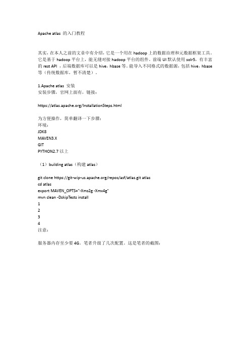
1.Apache atlas 安装安装步骤,官网上面有,链接:https:///InstallationSteps.html为方便操作,简单翻译一下步骤:环境:JDK8MAVEN3.XGITPYTHON2.7以上(1)building atlas(构建atlas)git clone https:///repos/asf/atlas.git atlascd atlasexport MAVEN_OPTS="-Xms2g -Xmx4g"mvn clean -DskipTests install1234注意:服务器内存至少要4G。
笔者升级了几次配置。
这是笔者的截图:文件很多,要下比较1-2个小时,中间可能也有fail。
(2)打包atlas(机器上已经装有hbase和solr)mvn clean -DskipTests package -Pdist1(机器上没有装hbase和solr,atlas自带hbase和solr)mvn clean -DskipTests package -Pdist,embedded-hbase-solr 1本文这里选了后一种。
(3)打包完,会在根目录下生成以下的包:(4)安装atlastar -xzvf apache-atlas-${project.version}-bin.tar.gzcd atlas-${project.version}123目前它会自动解压,这一步可以不要。
下载完成后,目录结构:其中,atlas_home/distro/target 下面,apache-atlas-1.0.0-SNAPSHOT-bin 是其解压后的目录:注意:接下来是配置步骤。


开源⾎缘分析⼯具atlas源码讲解需求说明:公司进⾏⾎缘分析,但是没有好⽤的⾎缘分析⼯具,从开源的社区找到了atlas,感觉很智能,可以⾃动分析sql语句,做到字段级别的拆分,回溯⾎缘很好⽤,下⾯就是atlas的代码讲解sql分析器:Antlr (ANother Tool for Language Recognition) 是⼀个强⼤的跨语⾔语法解析器,可以⽤来读取、处理、执⾏或翻译结构化⽂本或⼆进制⽂件。
它被⼴泛⽤来构建语⾔,⼯具和框架。
Antlr可以从语法上来⽣成⼀个可以构建和遍历解析树的解析器。
可以参考:Apache Atlas版本号:2.0.0从官⽅⽹站下载Apache Atlas2.0.0版本源代码,⽤开发⼯具(如IntelliJ IDEA)打开。
根⽬录结构⼀、3party-licenses第三⽅组件许可,可以看出Atlas主要⽤到的第三⽅技术组件,绝⼤部分是前端技术组件,janusgraph和titan是图数据库组件,JanusGraph是Titan的继承者,⽼版本⽤的是Titan,新版本是⽤的JanusGraph⼆、addons安装扩展组件源代码,主要是Atlas接⼊各种Hadoop元数据数据源的桥接代码,对应Atlas架构图中的部分:1、falcon-bridgefalcon桥接扩展模块,Apache Falcon是⼀个开源的hadoop数据⽣命周期管理框架, 它提供了数据源 (Feed) 的管理服务,如⽣命周期管理,备份,存档到云等,通过Web UI可以很容易地配置这些预定义的策略, 能够⼤⼤简化hadoop集群的数据流管理。
falcon-bridge主要负责将Apache Falcon元数据接⼊Atlas元数据管理系统。
bridge.FalconBridge类,提供了⼀系列注册Falcon元数据实体到Atlas系统的桥接⼯具API⽅法hook.FalconHook类,Falcon元数据通知事件钩⼦处理类这个模块的详细介绍说明和使⽤说明见官⽅⽂档:,或者本地⽂档:docs/src/site/twiki/Hook-Falcon.twiki2、falcon-bridge-shimfalcon桥接扩展垫⽚,即atlas的falcon桥接插件3、hbase-bridgeHbase桥接扩展模块,通过bin⽬录下的import-hbase.sh脚本导⼊Hbase元数据到Atlas系统,脚本调⽤了桥接代码类HBaseBridge,main⽅法⼊⼝。

Atlas Copco Stationary Air CompressorsGA5-7-11C-11-15-18-22-30C-30-37-45-55C-55-75-90C and GA30 W-37 W-45 W-55C W-55 W-75 W-90C WWith Elektronikon I or Elektronikon II regulatorUser manual for Elektronikon® I and II regulatorsCompressor type:. . . . . . . . . . . . . . . . . . . . . . . . . . . . . . . . . . . . . . . . Unit serial No. compressor:. . . . . . . . . . . . . . . . . . . . . . . . . . . . . . . . . . . . Air dryer type:. . . . . . . . . . . . . . . . . . . . . . . . . . . . . . . . . . . . . . . . . . Unit serial No. dryer:. . . . . . . . . . . . . . . . . . . . . . . . . . . . . . . . . . . . . . . . . Motor type:. . . . . . . . . . . . . . . . . . . . . . . . . . . . . . . . . . . . . . . . . . . . . Motor serial No.:. . . . . . . . . . . . . . . . . . . . . . . . . . . . . . . . . . . . . . . . . . . . Delivery date:. . . . . . . . . . . . . . . . . . . . . . . . . . . . . . . . . . . . . . . . . . . First start-up date:. . . . . . . . . . . . . . . . . . . . . . . . . . . . . . . . . . . . . . . . . . . Service Plan:. . . . . . . . . . . . . . . . . . . . . . . . . . . . . . . . . . . . . . . . . . . . Owner's machine No.:. . . . . . . . . . . . . . . . . . . . . . . . . . . . . . . . . . . . . . . . Selected lubricantsCompressor:. . . . . . . . . . . . . . . . . . . . . . . . . . . . . . . . . . . . . . . . . . . . Capacity:. . . . . . . . . . . . . . . . . . . . . . . . . . . . . . . . . . . . . . . . . . . . . . . . . . Bearing grease type, electric motor:. . . . . . . . . . . . . . . . . . . . . . . . . Dryer gearbox. . . . . . . . . . . . . . . . . . . . . . . . . . . . . . . . . . . . . . . . . . . Capacity . . . . . . . . . . . . . . . . . . . . . . . . . . . . . . . . . . . . . . . . . . . . . . . . . . . Printed Matter Nos.Atlas Copco compressor instruction book:. . . . . . . . . . . . . . . . . . . . Atlas Copco air dryer instruction book:. . . . . . . . . . . . . . . . . . . . . . . . . . Atlas Copco compressor parts list:. . . . . . . . . . . . . . . . . . . . . . . . . . Atlas Copco air dryer parts list:. . . . . . . . . . . . . . . . . . . . . . . . . . . . . . . . Atlas Copco logbook:. . . . . . . . . . . . . . . . . . . . . . . . . . . . . . . . . . . . . Local Atlas Copco RepresentativeName:. . . . . . . . . . . . . . . . . . . . . . . . . . . . . . . . . . . . . . . . . . . . . . . . . . . . . . . . . . . . . . . . . . . . . . . . . . . . . . . . . . . . . . . . . . . . . . . . . . . . . . . . . . . . . . . Address:. . . . . . . . . . . . . . . . . . . . . . . . . . . . . . . . . . . . . . . . . . . . . . . . . . . . . . . . . . . . . . . . . . . . . . . . . . . . . . . . . . . . . . . . . . . . . . . . . . . . . . . . . . . . . . Telephone:. . . . . . . . . . . . . . . . . . . . . . . . . . . . . . . . . . . . . . . Contact persons:Service:. . . . . . . . . . . . . . . . . . . . . . . . . . . . . . . . . . . . . . . . . . . . . Telex:. . . . . . . . . . . . . . . . . . . . . . . . . . . . . . . . . . . . . . . . . . Parts:. . . . . . . . . . . . . . . . . . . . . . . . . . . . . . . . . . . . . . . . . . . . . . . E-mail . . . . . . . . . . . . . . . . . . . . . . . . . . . . . . . . . . . . . . . . . . . . . . . . . . . . . . . . . . . . . . . . . . . . . . . . . . . . . . . . . . . . . . . . . . . . . . . . . . . . . . . . . . . . . . .SAFETY PRECAUTIONSTo be read attentively and acted accordingly before installing, operating or repairing the unit.These recommendations apply to machinery processing or consuming air or inert gas. Processing of any other gas requiresadditional safety precautions typical to the application which are not included herein.If necessary, install a suction duct. Never obstruct the air inlet. Care shall be taken to minimize the entry of moisture with the inlet air.4.The aspirated air shall be free from flammable fumes or vapours,e.g. paint solvents, that can lead to internal fire or explosion.5.Air-cooled units shall be installed in such a way that an adequateflow of cooling air is available and that the exhausted air does not recirculate to the inlet.6.Arrange the air intake so that loose clothing of people cannot besucked in.7.Ensure that the discharge pipe from the compressor to the aftercooler,air dryer or air net is free to expand under heat and that it is not in contact with or close to flammable material.8.No external force may be exerted on the air outlet valve; the connectedpipe must be free of strain.9.If remote control is installed, the unit shall bear an obvious signreading:DANGER: This machine is remotely controlled and may start without warning.As a further safeguard, persons switching on remotely controlled units shall take adequate precautions to ensure that there is no one checking or working on the machine. To this end, a suitable notice shall be affixed to the start equipment.10.On units with automatic start-stop system, a sign stating "Thismachine may start without warning" shall be attached near the instrument panel.11.In multiple compressor systems manual valves shall be installed toisolate each compressor. Non-return valves (check valves) shall not be relied upon for isolating pressure systems.12.Never remove or tamper with the safety devices, guards or insulationsfitted on the unit. Every pressure vessel or auxiliary installed outside the unit to contain air above atmospheric pressure shall be protected by a pressure-relieving device or devices as required.13.Pipework or other parts with a temperature in excess of 80 degreescelsius and which may be accidentally touched by personnel in nor-mal operation shall be guarded or insulated. Other high-temperature pipework shall be clearly marked.OWNERSHIP DA T AIn addition to normal safety rules which should be observed with stationary air compressors and equipment, the following safety directions and precautions are of special importance.When operating this unit, the operator must employ safe working practices and observe all related local work safety requirements and ordinances.The owner is responsible for maintaining the unit in a safe operating condition. Parts and accessories shall be replaced if unsuitable for safe operation.Installation, operation, maintenance and repair shall only be performed by authorized, trained, competent personnel.Normal ratings (pressures, temperatures, time settings, etc.) shall be durably marked.Any modification on the compressor or air dryer shall only be performed in agreement with Atlas Copco and under supervision of authorized,competent personnel.If any statement in this book, especially with regard to safety, does not comply with local legislation, the stricter of the two shall apply.These precautions are general and cover several machine types and equipment; hence some statements may not apply to the unit(s) described in this book.InstallationApart from general engineering practice in conformity with the local safety regulations, the following directives are specially stressed:1. A compressor or air dryer shall be lifted only with adequate equipmentin conformity with local safety rules.Loose or pivoting parts shall be securely fastened before lifting. It is strictly forbidden to dwell or stay in the risk zone under a lifted load.Lifting acceleration and retardation shall be kept within safe limits.Wear a safety helmet when working in the area of overhead or lifting equipment.2.Any blanking flanges, plugs, caps and desiccant bags shall beremoved before connecting up the pipes. Distribution pipes and connections shall be of correct size and suitable for the working pressure.3.Place the unit where the ambient air is as cool and clean as possible.2920 1377 031/2(continued on inside of cover)Atlas Copco Stationary Air CompressorsImportantThis book applies exclusively to the above-mentioned compressors with Elektronikon I or II regulator from following serial numbers onwards:GA5 up to GA11C:AII-145 000GA11 up to GA30C:AII-268 500GA30 up to GA55C:AII-380 000GA55 up to GA90C:AII-474 000No. 2920 1461 03Replaces 2920 1461 02Registration code:APC G5-11C/2002 / 38 / 984APC G11-30C / 38 / 989APC G30-55C / 38 / 980APC G55-90C / 38 / 9852003-09GA5-7-11C-11-15-18-22-30C-30-37-45-55C-55-75-90C and GA30 W-37 W-45 W-55C W-55 W-75 W-90C W With Elektronikon I or Elektronikon II regulator User manual for Elektronikon ® I and II regulators·Copyright 2003, Atlas Copco Airpower n.v., Antwerp, Belgium.Any unauthorized use or copying of the contents or any part thereof is prohibited. This applies in particular to trademarks, model denominations, part numbers and drawings.·This instruction book meets the requirements for instructions specified by the machinery directive 98/37/EC and is valid for CE as well as non-CE labelled machines.2920 1461 032User manualPage7Scrolling through all screens . . . . . . . . . . . . . . . . . . . . . . . . . 77.1Calling up outlet/dewpoint temperatures . . . . . . . . . . . . 97.2Calling up running hours . . . . . . . . . . . . . . . . . . . . . . . . 97.3Calling up loading hours . . . . . . . . . . . . . . . . . . . . . . . . 97.4Calling up motor starts . . . . . . . . . . . . . . . . . . . . . . . . . 107.5Calling up/resetting service timer. . . . . . . . . . . . . . . . . 107.6Automatic r e start aft e r voltag e failur e . . . . . . . . . . . . . 107.7Set of parameters. . . . . . . . . . . . . . . . . . . . . . . . . . . . . . 117.8Calling up/modifying unloading pressure . . . . . . . . . . 117.9Calling up/modifying loading pressure . . . . . . . . . . . . 117.10Calling up/modifying dewpoint warning temperature. 117.11Calling up/modifying service timer setting . . . . . . . . . 127.12Calling up/modifying unit for pressure . . . . . . . . . . . . 127.13Calling up/modifying unit for temperature . . . . . . . . . 127.14Selection between Y-D/DOL starting . . . . . . . . . . . . . . 127.15Activating automatic restart after voltage failure. . . . . 137.16Se le cting local/re mote control . . . . . . . . . . . . . . . . . . . 137.17Modifying parameter set. . . . . . . . . . . . . . . . . . . . . . . . 138Settings . . . . . . . . . . . . . . . . . . . . . . . . . . . . . . . . . . . . . 148.1Unloading/loading pressures . . . . . . . . . . . . . . . . . . . . 148.2Element outlet temperature. . . . . . . . . . . . . . . . . . . . . . 148.3Dewpoint temperature. . . . . . . . . . . . . . . . . . . . . . . . . . 148.4Service timer . . . . . . . . . . . . . . . . . . . . . . . . . . . . . . . . . 14ContentsPART 1 - ELEKTRONIKON I REGULATORPage1General description . . . . . . . . . . . . . . . . . . . . . . . . . . . . . . . . 31.1Automatic control of the compressor . . . . . . . . . . . . . . 31.2Protecting the compressor . . . . . . . . . . . . . . . . . . . . . . . 31.3Automatic restart after voltage failure . . . . . . . . . . . . . . 32Control panel . . . . . . . . . . . . . . . . . . . . . . . . . . . . . . . . . . . . . 33Display . . . . . . . . . . . . . . . . . . . . . . . . . . . . . . . . . . . . . . . . . . . 43.1Pictographs used on the screen . . . . . . . . . . . . . . . . . . . 43.2Main screen. . . . . . . . . . . . . . . . . . . . . . . . . . . . . . . . . . . 43.3Scrolling through all screens . . . . . . . . . . . . . . . . . . . . .54Shut-down warning . . . . . . . . . . . . . . . . . . . . . . . . . . . . . . . . 54.1Compressor element outlet temperature. . . . . . . . . . . . . 54.2Dewpoint temperature. . . . . . . . . . . . . . . . . . . . . . . . . . . 55Shut-down5.1Compressor element outlet temperature. . . . . . . . . . . . . 65.2Motor overload . . . . . . . . . . . . . . . . . . . . . . . . . . . . . . . . 66Service warning . . . . . . . . . . . . . . . . . . . . . . . . . . . . . . . . . . . 7PART 2 - ELEKTRONIKON II REGULATORPage1General description . . . . . . . . . . . . . . . . . . . . . . . . . . . . . . . 151.1Automatic control of the compressor . . . . . . . . . . . . . 151.2Protecting the compressor . . . . . . . . . . . . . . . . . . . . . . 151.3Automatic restart after voltage failure . . . . . . . . . . . . . 152Control panel . . . . . . . . . . . . . . . . . . . . . . . . . . . . . . . . . . . . 162.1LEDs/buttons/keys . . . . . . . . . . . . . . . . . . . . . . . . . . . . 162.2Pictographs . . . . . . . . . . . . . . . . . . . . . . . . . . . . . . . . . . 172.3Function keys . . . . . . . . . . . . . . . . . . . . . . . . . . . . . . . . 173Menu-driven control programs . . . . . . . . . . . . . . . . . . . . . 193.1Function of control programs. . . . . . . . . . . . . . . . . . . . 193.2Main screen. . . . . . . . . . . . . . . . . . . . . . . . . . . . . . . . . . 193.3Calling up other menus. . . . . . . . . . . . . . . . . . . . . . . . .194Quick look at actual compressor status . . . . . . . . . . . . . . . 205Status data menu . . . . . . . . . . . . . . . . . . . . . . . . . . . . . . . . . 205.1No message exists . . . . . . . . . . . . . . . . . . . . . . . . . . . . . 205.2 A shut-down message exists . . . . . . . . . . . . . . . . . . . . . 205.3 A shut-down warning message exists. . . . . . . . . . . . . . 215.4 A service warning message exists . . . . . . . . . . . . . . . . 215.5 A warning message exists . . . . . . . . . . . . . . . . . . . . . . .216Measured data menu . . . . . . . . . . . . . . . . . . . . . . . . . . . . . . 227Counters menu . . . . . . . . . . . . . . . . . . . . . . . . . . . . . . . . . . . 228Test menu. . . . . . . . . . . . . . . . . . . . . . . . . . . . . . . . . . . . . 22Page9Modify params menu . . . . . . . . . . . . . . . . . . . . . . . . . . . . . . 2210Modifying parameters . . . . . . . . . . . . . . . . . . . . . . . . . . . . . 2310.1Modifying loading/unloading pressures. . . . . . . . . . . . 2311Modifying protection settings . . . . . . . . . . . . . . . . . . . . . . . 2311.1Modifying settings for compressor element. . . . . . . . . 2412Modifying service plans . . . . . . . . . . . . . . . . . . . . . . . . . . . . 2413Programming clock function . . . . . . . . . . . . . . . . . . . . . . . .2513.1Programming start/stop/pressure band commands . . . 2513.2To activate/deactivate the timer . . . . . . . . . . . . . . . . . . 2613.3To modify a command . . . . . . . . . . . . . . . . . . . . . . . . . 2613.4To add a command . . . . . . . . . . . . . . . . . . . . . . . . . . . . 2713.5To delete commands . . . . . . . . . . . . . . . . . . . . . . . . . . .2714Configuration menu . . . . . . . . . . . . . . . . . . . . . . . . . . . . . . . 2814.1Programming compressor control modes. . . . . . . . . . . 2815Service menu . . . . . . . . . . . . . . . . . . . . . . . . . . . . . . . . . . . . . 2816Saved data menu . . . . . . . . . . . . . . . . . . . . . . . . . . . . . . . . . 2917Programmable settings . . . . . . . . . . . . . . . . . . . . . . . . . . . .3017.1Parameters. . . . . . . . . . . . . . . . . . . . . . . . . . . . . . . . . . . 3017.2Protections. . . . . . . . . . . . . . . . . . . . . . . . . . . . . . . . . . . 3117.3Service plan. . . . . . . . . . . . . . . . . . . . . . . . . . . . . . . . . .312920 1461 033User manualPART 1ELEKTRONIKON I REGULATOR1.3 Automatic restart after voltage failureFor compressors leaving the factory, this function is made inactive. If desired, the function can be activated. Consult Atlas Copco.WarningIf activated and provided the module was in the automatic operation mode, the compressor will automatically restart if the supply voltage to the module is restored.2Control panelRef.Designation Function1Stop buttonPush button to stop the compressor. LED (10) goes out.The compressor will stop after running in unloaded condition for about 30 seconds.2Start buttonPush button to start the compressor. LED (10) lights up indicating that the regulator is operative (in automatic operation).3DisplayIndicates the compressor operating condition, measured values and programmed parameters.1General description1.1 Automatic control of the compressorThe regulator maintains the net pressure between programmable limits by automatically loading and unloading the compressor.A number of programmable settings, e.g. the unloading and loading pressures, the minimum stop time and the maximum number of motor starts are taken into account.The regulator stops the compressor whenever possible to reduce the power consumption and restarts it automatically when the net pressure decreases.1.2 Protecting the compressorShut-downIf the compressor element outlet temperature exceeds the programmed shut-down level, the compressor will be stopped.This will be indicated on display (3). The compressor will also be stopped in case of overload of drive motor (M1) and,for air-cooled compressors, also the fan motor (M2).Shut-down warningIf the compressor element outlet temperature or dewpoint temperature (Full-Feature compressors) exceeds a programmed value below the shut-down level, this will also be indicated to warn the operator before the shut-down level is reached.Service warningIf the service timer exceeds a programmed value, this will be indicated on display (3) to warn the operator to carry out some service actions.52238FUser manual52236F42920 1461 03User manualImportantAlways consult Atlas Copco in case "t" or "test" appears on the display3.3 Scrolling through all screensIt is possible to scroll downwards and upwards through a number of screens by means of the upwards/downwards arrow keys (12 and 13). See section 7.4 Shut-down warningA shut-down warning message will appear in case of:-too high a temperature at the outlet of the compressor element-too high a dewpoint temperature (FF compressors)4.1 Compressor element outlet temperature1.In case the outlet temperature of the compressor elementexceeds the shut-down warning level (110 °C, not programmable), alarm LED (8) will light up and the relatedpictograph will appear blinking:Blinkingbar6.6Warning screen, element outlet temperature2.Press arrow key (12), r000 (register 000) appears.3.Press arrow key (12), the actual compressor elementtemperature appears:BlinkingC111Warning screen, element outlet temperatureThe screen shows that the temperature at the outlet of the compressor element is 111 °C.4.It remains possible to scroll through other screens (usingkeys 12 and 13) to check the actual status of other parameters.5.Press button (1) to stop the compressor and wait until thecompressor has stopped.6.Switch off the voltage, inspect the compressor and remedy.7.The warning message will disappear as soon as the warningcondition disappears.4.2 Dewpoint temperature1.In case the dewpoint temperature exceeds the shut-downwarning level (programmable), alarm LED (8) will light upand the related pictograph will appear blinking:Blinkingbar6.6Warning screen, dewpoint temperature2.Press arrow key (12), r000 (register 000) appears.3.Press arrow key (12), the actual dewpoint temperatureappears:Blinking°C9Warning screen, dewpoint temperatureThe screen shows that the dewpoint temperature is 9 °C. 4.It remains possible to scroll through other screens (usingkeys 12 and 13) to check the actual status of other parameters.5.Press button (1) to stop the compressor and wait until thecompressor has stopped.6.Switch off the voltage, inspect the compressor and remedy.7.The warning message will disappear as soon as the warningcondition disappears.2920 1461 035User manual5 Shut-downThe compressor will be shut down in case:-the temperature at the outlet of the compressor element exceeds the shut-down level-of error of the outlet pressure sensor-of overload of the drive motor and, on air-cooled compressors, also the fan motor5.1 Compressor element outlet temperature1.In case the outlet temperature of the compressor elementexceeds the shut-down level (120 °C, not programmable), the compressor will be shut down, alarm LED (8) will blink, automatic operation LED (10) will go out and following screen will appear:BlinkingShut-down screen, element outlet temperature2.Press enter key (5), r000 (register 000) appears.3.Press arrow key (12), the actual compressor elementtemperature appears:Blinking°C122Shut-down screen, element outlet temperatureThe screen shows that the temperature at the outlet of the compressor element is 122 °C.4.Switch off the voltage and remedy the trouble.5.After remedying and when the shut-down condition hasdisappeared, switch on the voltage and restart the compressor.5.2 Motor overload1.In case of motor overload, the compressor will be shut down,alarm LED (8) will blink, automatic operation LED (10)will go out and following screen will appear:BlinkingShut-down screen, motor overload2.Switch off the voltage and remedy the trouble.3.After remedying and when the shut-down condition hasdisappeared, switch on the voltage and restart the compressor.52236F2920 1461 036User manual2920 1461 037°C 82°CkHrs r001°CP003°C8LK LLL L LL LL2920 1461 038Parameter Used forscreensP001Unload pressure settingP002Load pressure settingP003Warning level setting for dewpoint temperature P004Setting of service timerP005Setting of unit for pressureP006Setting of unit for temperatureP007Selection between Y-D or DOL startingP008Selection for function "Automatic restart after voltage failure" (active or not, only for AtlasCopco)P009Selection between Local/Remote controlP010Changing set of programmed parameters (only for Atlas Copco)7.1Calling up outlet and dewpointtemperaturesStarting from the Main screen:bar6.61.Press arrow key (12), the outlet temperature will be shown:°C83The screen shows that the outlet temperature is 83 °C.2.Press arrow key (12), the dewpoint temperature will beshown:°C3The screen shows that the dewpoint temperature is 3 °C. e keys (12 and 13) to scroll downwards or upwardsthrough the screens.7.2 Calling up running hoursStarting from the Main screen:bar6.61.Press arrow key (12) until r001 is shown and then pressenter key (5):kHrs2.381The screen shows the unit used ( kHrs or hours x 1000) and the value 2.381 : the running hours of the compressor are 2381 hours.7.3 Calling up loading hoursStarting from the Main screen:bar6.652236F1.Press arrow key (12) until r002 is shown and then pressenter key (5):kHrs1.755The screen shows the unit used ( kHrs or hours x 1000) and the value 1.755 : the loading hours of the compressor are 1755 hours.7.4 Calling up motor startsStarting from the Main screen:bar6.61.Press arrow key (12) until r003 is shown and then pressenter key (5):3This screen shows the number of motor starts times 1000. Press enter key (5) to return to the register screens.2.Press arrow key (12) until r004 is shown and then pressenter key (5):226This screen shows the number of motor starts to be added to the reading in register r003. In this example, the number of motor starts is 3226.7.5 Calling up/resetting service timerStarting from the Main screen:bar6.61.Press arrow key (12) until r005 is shown and then pressenter key (5):kHrs1.191The screen shows the unit used ( kHrs or hours x 1000) and the value 1.191 : the compressor has run for 1191 hours since previous service.Resetting the service timerAfter servicing (see section 6), the timer has to be reset:1.Scroll to register screen r005, the reading (e.g. 4.000 )will appear.2.Press reset key (4), the reading will blink (indicating thatresetting is possible).3.Press enter key (5) to reset the timer to "0.000" or pressreset key (4) to cancel the operation.7.6 Automatic restart after voltage failureStarting from the Main screen:bar6.6Press arrow key (12) until r006 is shown and press enter key (5):-if 0 appears, the function Automatic restart after voltage failure is not active-if 1 appears, the function Automatic restart after voltage failure is active52236F52236F1.Press arrow key (12) until P007 is shown and press enterkey (5). The actually used starting mode is blinking: 1 for Y-D (star-delta) or 0 for DOL (direct-on line).e arrow keys (12 and 13) to select another starting mode.3.Press enter key (5) to program the new starting mode andto return to the parameter screens.7.15 Activating Automatic restart aftervoltage failureThis parameter, accessible in screen P008 , can only be modified after entering a password. Consult Atlas Copco if this function should be activated.7.16 Selecting between Local or RemotecontrolStarting from the Main screen:bar6.61.Press arrow key (12) until P009 is shown and press enterkey (5). The actually used control mode is blinking: 0 for Local control mode or 1 for Remote control mode.e arrow keys (12 and 13) to select another mode.3.Press enter key (5) to program the new control mode and toreturn to the parameter screens.7.17 Modifying the Parameter setThis parameter, accessible in screen P010 , can only be modified after entering a password.8Settings8.1Unloading/loading pressuresMinimum Nominal Maximum Unloading pressure13 bar. . . . . . . . . . . . . . . . . . . . . . . . . . . . . . . . . . . . bar(e) 4.112.51313 bar Full-feature. . . . . . . . . . . . . . . . . . . . . . . . . . bar(e) 4.112.512.810 bar. . . . . . . . . . . . . . . . . . . . . . . . . . . . . . . . . . . . bar(e) 4.19.51010 bar Full-feature. . . . . . . . . . . . . . . . . . . . . . . . . . bar(e) 4.19.59.87.5 bar. . . . . . . . . . . . . . . . . . . . . . . . . . . . . . . . . . . . bar(e) 4.177.57.5 bar Full-feature. . . . . . . . . . . . . . . . . . . . . . . . . . bar(e) 4.177.3100 psi. . . . . . . . . . . . . . . . . . . . . . . . . . . . . . . . . . . bar(e) 4.1 6.97.4100 psi Full-feature. . . . . . . . . . . . . . . . . . . . . . . . . bar(e) 4.1 6.97.2125 psi. . . . . . . . . . . . . . . . . . . . . . . . . . . . . . . . . . . bar(e) 4.18.69.1125 psi Full-feature. . . . . . . . . . . . . . . . . . . . . . . . . bar(e) 4.18.68.9150 psi. . . . . . . . . . . . . . . . . . . . . . . . . . . . . . . . . . . bar(e) 4.110.310.8 150 psi Full-feature. . . . . . . . . . . . . . . . . . . . . . . . . bar(e) 4.110.310.6 175 psi. . . . . . . . . . . . . . . . . . . . . . . . . . . . . . . . . . . bar(e) 4.11212.5 175 psi Full-feature. . . . . . . . . . . . . . . . . . . . . . . . . bar(e) 4.11212.3Loading pressure13 bar. . . . . . . . . . . . . . . . . . . . . . . . . . . . . . . . . . . . bar(e)411.912.913 bar Full-feature. . . . . . . . . . . . . . . . . . . . . . . . . . bar(e)411.912.710 bar. . . . . . . . . . . . . . . . . . . . . . . . . . . . . . . . . . . . bar(e)48.99.910 bar Full-feature. . . . . . . . . . . . . . . . . . . . . . . . . . bar(e)48.99.77.5 bar. . . . . . . . . . . . . . . . . . . . . . . . . . . . . . . . . . . . bar(e)4 6.47.47.5 bar Full-feature. . . . . . . . . . . . . . . . . . . . . . . . . . bar(e)4 6.47.2100 psi. . . . . . . . . . . . . . . . . . . . . . . . . . . . . . . . . . . bar(e)4 6.37.3100 psi Full-feature. . . . . . . . . . . . . . . . . . . . . . . . . bar(e)4 6.37.1125 psi. . . . . . . . . . . . . . . . . . . . . . . . . . . . . . . . . . . bar(e)489125 psi Full-feature. . . . . . . . . . . . . . . . . . . . . . . . . bar(e)488.8150 psi. . . . . . . . . . . . . . . . . . . . . . . . . . . . . . . . . . . bar(e)49.710.7 150 psi Full-feature. . . . . . . . . . . . . . . . . . . . . . . . . bar(e)49.710.5 175 psi. . . . . . . . . . . . . . . . . . . . . . . . . . . . . . . . . . . bar(e)411.412.4 175 psi Full-feature. . . . . . . . . . . . . . . . . . . . . . . . . bar(e)411.412.2The recommended minimum pressure difference between loading and unloading is 0.6 bar.8.2Element outlet temperatureThe settings for warning (110 °C) and shut-down (120 °C) arenot programmable.8.3Dewpoint temperatureThe nominal warning setting is 8°C.8.4Service timerThe nominal setting for compressors using Roto-injectfluid is4000 running hours. If using mineral oil, the setting must bedecreased to 500 or 1000 running hours (see the relatedInstruction book).。

CDP使用指南2021年05月12日目录1.文档说明 (8)2.CDP平台介绍 (8)2.1.CDP平台简介 (9)2.2.C LOUDERA M ANAGER概览 (10)2.3.C LOUDERA R UNTIME (11)2.4.工具 (11)2.5.设置对基于阿里云部署的CDP的访问权限 (12)2.5.1.配置SOCKS代理 (12)2.5.2.启动SOCKS代理 (12)2.5.3.配置Google Chrome浏览器以使用代理 (13)2.5.4.网络安全组 (14)3.CLOUDERA MANAGER (15)3.1.术语 (15)3.1.1.部署 (16)3.1.2.动态资源池 (16)3.1.3.集群 (16)3.1.4.主机 (16)3.1.5.机架 (16)3.1.6.服务 (16)3.1.7.服务实例 (17)3.1.8.角色 (17)3.1.9.角色实例 (17)3.1.10.角色组 (17)3.1.11.主机模板 (17)3.1.12.网关(Gateway) (17)3.1.13.Parcel (18)3.1.14.静态服务池 (18)3.2.C LOUDERA M ANAGER架构 (18)3.2.1.心跳 (19)3.3.状态管理 (19)3.4.C LOUDERA M ANAGER 管理控制台 (20)3.4.1.Cloudera Manager管理控制台主页 (24)3.4.2.自动登出 (28)3.5.进程管理 (30)3.6.主机管理 (30)3.7.C LOUDERA M ANAGER A GENT (31)3.7.1.cm_processes (31)3.8.资源管理 (32)3.9.用户管理 (33)3.10.安全管理 (33)3.11.使用C LOUDERA M ANAGER监控集群 (33)3.12.C LOUDERA M ANAGEMENT S ERVICE (35)3.12.1.健康测试 (35)3.12.2.指标收集和显示 (36)3.12.3.事件、警报和触发器 (36)3.13.集群配置概述 (37)3.14.服务器和客户端配置 (38)3.15.C LOUDERA M ANAGER API (39)3.16.虚拟专用集群和C LOUDERA SDX (39)3.16.1.分离计算和数据资源的优势 (40)3.16.2.架构 (40)3.16.3.权衡性能 (42)3.16.4.虚拟专用集群的兼容性注意事项 (42)3.16.5.虚拟专用集群的网络注意事项 (47)4.CDP核心组件 (53)4.1.C LOUDERA R UNTIME组件版本 (53)4.2.分布式文件系统HDFS (57)4.3.实时数据库HB ASE (58)4.4.列式存储引擎K UDU (60)4.5.统一资源管理和调度框架 (61)4.6.分布式计算框架–T EZ (66)4.7.数据仓库组件–H IVE (68)4.8.SQL分析引擎I MPALA (69)4.9.HB ASE SQL查询引擎P HOENIX (71)4.10.C LOUDERA整合全文检索引擎 (73)4.11.分布式内存计算框架–S PARK (76)4.12.数据库接入工具S QOOP (78)4.13.C LOUDERA一站式安全管理 (83)4.14.分布式消息队列K AFKA (93)4.15.A PACHE A TLAS (95)5.CLOUDERA安全概述 (98)5.1.概述 (98)5.1.1.安全要求 (99)5.1.2.安全等级 (99)5.1.3.Hadoop安全架构 (100)5.2.认证概述 (101)5.2.1.Kerberos概述 (102)5.2.2.Kerberos部署模型 (103)5.2.3.使用TLS/SSL进行安全的Keytab分发 (109)5.2.4.使用向导或手动过程来配置Kerberos身份验证 (110)5.2.5.集群组件使用的身份验证机制 (110)5.3.加密概述 (111)5.3.1.保护静态数据 (111)5.3.2.保护传输中的数据 (114)5.3.3.Hadoop项目中的数据保护 (115)5.3.4.加密机制概述 (117)5.4.授权概述 (117)5.4.1.Hadoop中的授权机制 (118)5.4.2.与身份验证机制的身份验证机制集成 (119)5.4.3.Hadoop项目中的授权 (120)5.5.治理概述 (121)5.5.1.什么是Apache Atlas? (121)5.5.2.Apache Atlas使用元数据创建血统关系 (121)5.5.3.添加到实体元数据使搜索更加容易 (121)5.5.4.Apache Atlas体系结构 (122)6.CLOUDERA最佳实践 (123)6.1.I MPALA分区 (123)6.1.1.文件计数和文件大小 (123)6.1.2.分区注意事项 (124)6.1.3.指南总结 (126)6.2.I MPALA性能 (126)6.2.1.Kudu RPC (126)6.2.2.设立专门的协调员 (127)6.2.3.按需元数据和元数据管理 (130)6.3.加速S PARK ML应用 (153)6.3.1.Spark ML的原生数学库 (153)6.3.2.启用libgfortran库 (154)6.3.3.启用英特尔MKL库 (156)6.3.4.性能比较 (157)7.故障排查 (159)7.1.安全故障排查 (159)7.1.1.错误信息和各种故障 (159)7.1.2.身份验证和Kerberos问题 (167)7.1.3.HDFS加密问题 (179)7.1.4.Key Trustee KMS加密问题 (181)7.1.5.对Cloudera Manager中的TLS/SSL问题进行故障排除 (182)7.2.YARN、MR V1和L INUX OS安全性 (185)7.2.1.MRv1和YARN:jsvc程序 (185)7.2.2.仅限MRv1:Linux TaskController (186)7.2.3.仅限YARN:Linux容器执行器 (186)7.3.对I MPALA进行故障排除 (187)7.3.1.使用Breakpad Minidumps进行崩溃报告 (188)7.4.对A PACHE Y ARN进行故障排查 (190)7.4.1.在YARN上对Docker进行故障排除 (190)7.4.2.对Linux Container Executor进行故障排除 (200)7.5.对HB ASE进行故障排除 (202)7.5.1.使用HBCK2工具修复HBase集群 (203)7.5.2.Thrift Server在收到无效数据后崩溃 (203)7.5.3.HBase正在使用比预期更多的磁盘空间 (204)7.5.4.对RegionServer分组进行故障排除 (205)7.6.对APACHE KUDU进行故障排除 (206)7.6.1.启动或重启主服务器或者Tablet服务器时出现问题 (206)7.6.2.磁盘空间使用问题 (207)7.6.3.性能问题 (208)7.6.4.可用性问题 (214)7.6.5.象征堆栈跟踪 (216)7.6.6.在多主服务器部署中从死掉的Kudu主服务器中恢复 (218)7.7.对C LOUDERA S EARCH进行故障排除 (218)7.7.1.故障排除 (218)7.7.2.动态Solr分析 (219)7.7.3.其他故障排除信息 (220)7.7.4.找出Cloudera Search部署中的问题 (220)7.7.5.Cloudera Search配置和日志文件 (223)7.8.对H UE进行故障排查 (226)7.8.1.Hue负载平衡器无法在各个Hue服务器之间平均分配用户 (226)7.8.2.无法使用SAML对Hue中的用户进行身份验证 (227)7.8.3.清理旧数据以提高性能 (227)7.8.4.无法使用提供的凭据连接到数据库 (229)7.8.5.在Hue UI上激活Hive查询编辑器 (230)7.8.6.查询执行在Hue中完成,但显示为在Cloudera Manager Impala查询页面上执行 (231)7.8.7.查找Hue超级用户列表 (232)7.8.8.通过Knox访问Hue时,用户名或密码不正确 (233)7.8.9.从Knox访问Hue UI时出现HTTP 403错误 (234)7.8.10.无法从Knox Gateway UI访问Hue (236)7.8.11.引荐检查失败,因为域与任何受信任的来源都不匹配 (239)7.8.12.无法查看Snappy压缩文件 (239)7.8.13.启用SAML时出现“未知属性名称”异常 (241)7.8.14.Impala查询因无效的查询句柄错误而失败 (242)7.8.15.PostgreSQL支持的服务失败或挂起 (243)7.8.16.验证Hue中的LDAP用户时出错 (244)7.8.17.从负载均衡器访问Hue时出现502代理错误 (245)7.8.18.提交Hive查询后,无效的方法名称:“ GetLog”错误 (246)7.8.19.在Hue中提交查询时出现“授权异常”错误 (246)7.8.20.无法更改Hue中的压缩表 (248)7.8.21.从Hue访问“搜索”应用程序(Solr)时出现连接失败错误 (249)7.8.22.从顺化下载查询结果需要时间 (250)7.8.23.启用TLS后,Hue Load Balancer无法启动 (250)7.8.24.无法终止以Kerberized集群运行的Hue作业浏览器中的Hive查询 (251)7.8.25.无法在受Knox保护的集群上的Hue中查看或创建Oozie工作流 (252)7.8.26.1040,“连接太多”异常 (253)8.参考资料 (254)1.文档说明本文档主要是基于阿里云部署的CDP的操作使用和介绍,关于CDP平台的操作和使用信息来源Cloudera官网,大家可以访问https:///cdp-private-cloud-bas e/latest/index.html来获取对应的信息。

一. 控制屏(图1.1)电脑显示屏/按钮/键代号名称功能1 停机按钮按此键停止空气压缩机,显示屏退出.空压机将空载运行大约30秒后停机.2 启动按钮按此按键启动空压机.显示屏显示调节器的运行状态.显示屏退出(如果空压机手动调为空载时)3 显示器显示出空压机的运转状态,协助需求或故障4 翻业按键在显示屏上翻页5 横移按键用水平箭头选择显示参数,只有向右的箭头对应的参数才能修改6 LED上的电压显示开关开启时的电压7 LED总报警当维护器警告或停机警告条件存在时或传感器不受控制时报警灯亮8 LED总在传感器的停机功能消失或紧急停机后的情况下报警灯会闪烁.9 功能键控制并执行程序.S3 紧急停机按钮在紧急情况下立即停止空压机,在修复后.将此按钮拔出.10 报警符号11 自动运行符号12 电源指示灯(1.1)二. 功能键使用的功能键:手动调节空压机的负荷调出或设定程序重新设定电动机的过负荷,停机,维护器信息或紧急停机.进入调节器所收集的数据.功能键都根据显示菜单的不同而不同.实际上都缩写并显示有关键的最底部一行,普通的缩写如下:缩写名称功能Add 增加指令用来增加空压机的自动启动/停机(日期)Back 返回指令返回到的选择或菜单Canc 取消当设定参数有误时.用来取消已设定的数dle 删除用来删除空压机的自动启动/停机时间Help 帮助帮助寻找Atlas Copco的内部地址Lim 上下限显示允许设定的上下极限数据Load 负载手动操作空压机负载Main 回到主目录从任一画面回到主目录Menu 菜单从主画面开始可进入子目录Menu 菜单从任一子目录返回到先前的目录Mod 修改修改设定参数Prog 编写输入将新的设定数据编写输入Rset 重新设定重新设定计时器及信息Rtrn 回归回归到前一页或前一目录Unld 空载手动操作空压机空载Xtra 额外的找寻调节器的构造模式三. 控制程序的功能程序/功能说明主屏幕简单地显示空压机的运转状态,是进入所有功能画面的出入口状态数据调出空压机的维护功能状况:停机.停机警告,维修期限快到的警告以及警告的数据,也可重新设定停机参数,马达超载和维修条件的数据.测量数据可调出:实际测量数据,还有如马达的超负荷保护这样一些输入数据计数器可调出:运行时间,带负荷运转小时数,马达开启次数,电脑运行时间数,负荷循环次数. 试验试验显示屏修改设定修改以下设定:参数(如空载和负载时的压力)保护(如停机温度)维护计划.维护器调出维护计划并重新设定计时器已存数据调出上次关机,紧急停机时已存的数据1.5.2 主屏幕当开启电源开关时,主屏幕自动简单地显示空压机的操作状况.Delivery Air(输送空气)Bar(压力) 7.0 ↓Auto Loaded(自动负载)Menu(菜单) Unld(空载)F1 F2 F3如果功能键或↓几分钟不用的话显示屏就自动返回到主屏幕.无论在哪个子目录,只要按:Main就会返回到主目录.1.5.3 调出其他子菜单.从主目录开始: 用↓可快速浏览空压机的实际状态(见1.5.4节) .按Menu键(F1),供选择的数据就会跟在水平箭头后面:也可按横向移动箭头5来选择这个菜单或用↓来翻页到带有水平箭头的子目录为止,然后按水平键来选择这个菜单.1.5.4 迅速查看空压机的实际状态步骤1.从主目录开始(见1.5.2节),按↓键,就会显示相似下面的一个画面:Auto Operation(自动运转)Local Control(负荷控制)Tiner Active(激活计时器)Main (主画面) Help Xtra ↓F1 F2 F3图1.11所示为空压机实际状态显示第一行指出调节器的运行是自动还是手动的:<Auto Operation>表示调节器自动调节空压机的运转.如:Local(负载),Unlocal(空载),根据程序参数Sotp(停机)和 Restart(重启).<Man Operation>表示手动操作,如果在主屏幕上按了”Unload”键后调节器的自动压力控制就被打断了.第二行指出调节器是现场控制方式(Local control)还是远程控制方式(Remote control): <Local control>表示Start/Stop,load/unload(即开启/停止,负载/空载)的按钮是激活状态,可直接按.<Remote control>表示功能键是远方控制的,就地操作无效.第三行表示为计时器的开机停机命令是否在激活状态,见(1.15.13)2. 按↓键可以获得其它数据(如空压机的实际运行条件)1.5.5 状态数据菜单状态数据子目录给出了有关空压机保护功能的状态信息(如停机 .停机警告,维护器警告和一般警告)以及重新设定停止,马达超载和服务条件.步骤:从主屏幕开始(见1.5.2)按Menu(F1),用水平箭头选择状态数据.按横向移动键(LED中的5) 1.5.5.1无信息存在在这种情况下,LED的7不存在,显示屏的信息表明所有条件正常(Fig1.12)All conditionsAre OKMenuF1 F2 F3图1.12状态数据屏的实例1.5.5.2 有停机信息存在在空压机停止时,LED中7会闪光.如果是由于空压机的出口温度过高导致的停机,就会显示以下屏幕:Element outletC 122Shd Max 120Menu** **RsetF1 F2 F3图1.13状态数据屏的实例1. 指示器(**)会闪光.屏幕显示传感器(空压机的出口)的实际可读温度(122℃),及空压机停机(Shd)设定(120℃).2. 可以继续翻页到其它菜单,检查其它参数值.当返回到数据菜单时,可供选择的(“Shutdowns”会闪光,按横向移动键5返回到停机屏幕来选择(“Shutdowns”).重新设定停机参数1. 关闭电源开关后处理问题,在修复完毕并且停机显示消失后,开启电源开关,按Rset(重新设定)键.2. 按Menu和 Main键返回主屏幕并按I键重新启动空压机.马达超载之重设1. 关闭电源开关并处理问题,过负荷继电器(F2)冷却后会自动重新设定,但冷却风扇的断路器(Q15)必须重置.开启电源开关,按Rset(重新设定)键.2. 按Menu和Main键返回主屏幕并重启空压机.1.5.5.3存在停机警告信息1.如有停机警告出现,LED上的7灯亮,会出现类似下面的屏幕:Delivery airBar 7.0*Shutd Warn*Menu** **UnldF1 F2 F3图1.14停机报警的实例2指示器(**)闪光和信息*Shutd Warn*会交替出现,无论空压机是空载还是带负载运行.3. 按Menu和横向移动键5来选择状态数据菜单:保护(Protection)会闪光.4. 按横向移动键5来选择报警闪光项.屏幕显示如下:Element outletC 116Shdw Max 110Menu** **F1 F2 F3图1.15停机报警的实例屏幕上说明空压机温度太高(116℃),参照第六节修复问题.5. 如有需要,按O键直到空压机停止为止.6. 关闭电源开关,检查并修复空压机.7. 当报警条件除去时,报警信号也会消失.1.5.5.4出现维护器报警信号1.LED上的7灯亮,会出现类似下面的屏幕,如图1.16所示:Delivery airBar 7.0*Serv Requir*Menu** **UnldF1 F2 F3图1.16报警屏幕的实例2指示器(**)闪光和维护器报警信号会交替出现,无论空压机是空载运行还是带负荷运行.3. 按Menu和横向移动键5来选择状态菜单:维护器项(Service),闪光4. 翻页并按横向移动键5来选择下面二报警闪光项:<Inputs>:如果维护器超出了预设的报警标准(如油分的最高压力露点).见8.2节.<Plans>:如果维护计划时间间隔超限.5. 停止空压机并关闭电源6. 如果维护器信息为上述的<Inputs>(油分故障):就更换分离器.开启电源,翻到状态数据菜单的<Inputs>并按Rset键,重新设定维护信息.7. 如果维护器信息为上述的<Plans>:执行有关指示计划的维修动作,重新设定1.5.15节里记述的有关计划的计时器.1.5.5.5 出现报警信号及处理1. LED上的7灯亮,在屏幕上会出现一个报警信息.2. 指示器(**)闪光和服务报警信号会交替出现,无论空压机是空载运行还是负荷运行.此警告指出:空压机的冷却水,冷却水的出口温度超过了设计报警温度.内置干燥机(配有干燥机的空压机),露点温度超出了报警温度.3. 停机4. 关闭电源,检查并修复空压机.1.5.6 测量数据菜单功能:按Menu(F1) 按↓到 Measured data 画面按横向移动箭头5激活菜单Delivery airBar 7.0Menu ↓F1 F2 F3图1.17状态数据屏的实例2按↓可见一组实际测量数据(见图1.9)3. 如果有一个传感器连接到了停机,维护器或报警功能上面的话,只要按横向移动箭头5就可以调出与其有关的实际测量数据.1.5.7 计数器菜单功能: 允许操作员调出:运行时间带负荷时间马达启动次数电脑运行时间步骤1. 从主屏幕开始(见1.5.2) 按Menu(F1)按↓到Counters画面按横向移动箭头5激活此菜单2. 按↓就可见到上面提到的数据.(也可见图1.9)1.5.8 试验菜单功能可修改图1.9提到的许多数据.步骤1. 从主屏幕开始(见1.5.2) 按Menu(F1)按↓到Modify setting画面,按横向移动箭头5激活菜单2. 水平箭头将指向Display test选项.3. 按→←第一条(负载压力)及它的设定都会出现4. 使用↓翻到水平箭头指向的已修改的参数.1.5.10.1 空/负载上下限压力修改压力段如果合适的话,操作员可以随空/负载压力的不同而设定二个压力段(1段和2段).1段的设定指示为:<Loading pressure>及<Unloading pressure>,2段的设定指示为:<Loading pressure2>及<Unloading pressure2>.例如:1 段压力设定:Loading pressur: 6.4barUnloading pressur: 7.0bar2 段压力设定:Loading pressur: 4.0barUnloading pressur: 6.0bar步骤1. 负载压力参数的设定1) 参照上节选择负载压力参数:Loading pressBar 6.0Menu Mod ↓F1 F2 F3图1.18为修改参数菜单3).Lim(F2)键可查看参数的上下限,用↓或↑调整压力参数值.4).按Prong(F1)编写输入新设定值,或按Canc(F3)取消修改操作.2. 修改空载压力的设定同上.3. 如果需要修改空/负载压力段2的话,则重复上述步骤..1.5.11 修改保护设定功能1. 修改保护设定停机保护(<Shd>)由于出口温度的问题停机警告(<Shdw>)由于出口温度的问题警告(<Warn>),如:冷却水回路或露点警告维护器报警(<Serv>),如:DP油分故障(最大压力降)2. 检查空压机的一些情况,如:马达超载通讯的状态.图1.9所示的参数表.注意:有些参数不能修改步骤1. 从主屏幕开始(见1.5.2)按Menu(F1)按↓到Modify setting画面,按横向移动箭头5激活此菜单2. 用↓翻页,水平箭头将指向Protection选项.3. 按→←第一条(Delivery air)及它的值都会出现.4. 使用↓翻到水平箭头指向的已修改的参数.1.5.11.1 温度上下限之设定修改1.参阅上节选择出口温度参数(Element outet):Element OutletC 94 →Shd Max 120Menu Mod ↓F1 F2 F3图1.20为修改参数菜单2.上屏幕显示的是正常温度94℃及停机温度120℃.按MOD(F2),数字120闪动,如图1.21所示:Element OutletC 120(闪动)Prog Lim Canc ↓F1 F2 F3图1.21为修改参数菜单3. Lim(F2)键可查看参数的上下限。
ATLAS高压空压机操作手册一.电气运行1.电气设备的概述:请参考接线图及元器件布置图,另外马达的电气参数在压缩机接线图上有标出。
2.传感器(检测设备)它们构成了保证系统安全运行的控制系统,它们都安装在不同的实时检测点:A 各级空气温度传感器B水温传感器C空气压力传感器D油压传感器F水流量检测开关G电气操作控制阀(1)检测压缩机各级出口的排气温度,若遇到排气温度过高,会发生报警并关闭压缩机(2)检测压缩机冷却水循环回路出口温度,能调节压缩空气温度,若过高会报警并关闭压缩机(3)控制气压进入储气罐的压力,控制压缩机加载或卸载在异常高压下(4)它用于控制润滑回路终端的油压,若压力过低会关闭压缩机(5)它控制压缩机循环回路出口流量。
在起动或运行中若水不够多,25秒后会自动关闭3.电气柜这里有整个电气系统,包括三相马达驱动、过程控制器、不同内容的界面显示、控制单元(开/关,手动、自动操作选择)、运行起动0/1(自动状态下)。
通过显示终端可看到系统各级运行状况,可以变换操作语言,以及某些参数的更改(温度、压力、时间与其它一些数据),请参考本文献附录最后的框图,那里给出了元件的布置情况,它们包括保证整个系统安全运行的各种器件:A 保护设置B电力C多种控制D人机对话界面E扩展接口(1)电柜门上的电气元器件安装:包括:电源主开关:它能将整个压缩机装置同供电系统完全隔离。
急停按钮:它可以立即停止压缩机工作,直到排除危险才可重新启动传送终端:在压缩机工作时,用它可以进行人机对话,故障处理,调整参数和维护。
另外还包括:显示压缩机状态参数、报警故障显示、微处理器起动、停止、复位、测试。
(2)电柜后部的元器件:它包括压缩机运行的各种特有电气元件,如:各种保险。
回路断路器(磁—热)电源交流接触器,变压器;用于管理整个压缩机起动、开停过程的控制器;用于人—机对话的传送终端,继电器控制设备,接线端子等。
二.预起动时的检查和调整1.较长时间封存后必须进行检查,必须是在停机和切断电源后进行项目:A 检查设备的环境状况B去掉保护和防尘罩C清理掉保护油D重新装上拆下的零件(马达,皮带,安全阀,压力/ 温度表)E检查电机绝缘及轴承F拆下马达轴锁紧螺母G手动检查压缩机旋转时的自由度H手动检查马达旋转时的自由度2.在试运行时,要检测的项目,在系统关闭情况下进行检测与调整项目:A检查存放环境条件B检查安全检测元件的电气连接状况(包括:油压、传感器,空气压力传感器,控制电磁阀,水电阀,水回路电气控制元件,空气温度传感器等)C检查参数,设定(包括油压、空气压力、空气温度)D检查皮带松紧E检查气路、水路的管道连接情况F检查供气隔离阀是否打开G检查水系统供给阀开否H油位检查I检查电气连接,电压频率必须与电机铭牌上的要一致J补水排水保证回路无泄露3.驱动方面检测,必须检测主电路相序A电机马达B起动设备C电气系统的主电路(1)合上断路器(2)检查皮带旋转方向是否与主体结构上的箭头标示一致(皮带轮侧看顺时针旋转正确)(3)如果方向错了,要调换马达相序4.空压机起动A.合上断路器B.星---三角起动阶段,第一段到第二段要10~12秒延迟C.如果压缩机未起动,在确认所有检测项目和参数调整都已正确完后,按消除报警按钮D.如果动行几秒后,压缩机停下来,检查星---三角转换是否正确E.检查油压(1.5~2BAR)F.检查一级,二级气压(压力表)G.用传输终端设置空气温度传感器的设定值,逐渐减少预设值,检测它们的性能直到它们与实际相等,检测之后,恢复原来的状态H.检查排气压力传感器的运行灵敏度,是否良好,是否失去动能?I.检测循环水流量检测开关是否与实际相等J.检测入口流量K.检测水温L.确认水循环回路有无泄露5.停机切断电源,检查项目:A.按“0”停机B.关掉断路开关C.关掉压缩机出气排气阀D.关掉压缩机进气气阀E.如果该水回路有负荷,关闭主机的进出水阀,在冬天,如考虑到结冻,若使用无抗冻剂水,要排掉冷却水三.起动、运行、关闭1.在自动模式下和手动模式下操作的一般规则:无论在哪种模式下压缩机起动和停止都处于非载荷配置下进行,忽略系统内部压力,上载自动完成自动模式下的运行:电气控制回路作如下说明:A压缩机电源B操作人员已选择自动运行C主辅电机星/三角转换起动均需`10~12秒延迟D排气温度,热继电马上计数,如果有一个故障,系统会自动停下来E安全起动延迟:油压要“X”秒,则设定点水流量要“Y”秒到达设定值F安全设施如多次触发,要考虑重新调整状态设定G罐内压力慢慢上升,当压力达到并超过设定高端值时,压缩机会自动卸载。
Apache服务器的默认设置试验目的:掌握apache的安装和启动方法。
查看apache的默认设置。
试验步骤:1.#rpm –qa | grep httpd --确认apache已安装。
2.#service httpd start --或使用apachectl start。
stopstatusconfigtest --语法检查3.#vi /etc/httpd/conf/httpd.conf --查看默认配置。
4.http://127.0.0.1修改apache的配置试验目的:掌握apache的基本配置。
掌握.htaccess文件的使用方法。
配置系统用户的个人web站点。
试验步骤:1.#mkdir /var/www/html/private2.#touch /var/www/html/private/test --生成测试文件。
3.#vi /etc/httpd/conf/httpd.confAccessFileName .htaccess --确认已启用.htaccess文件。
<Files ~”^\.ht”>Order allow,denyDeny from all</Files><Directory “/var/www/html/private”> --允许目录中的.htaccess文件覆盖主AllowOverride Options 配置文件的设置。
</Directory> --.htaccess文件只针对所在目录设置访问控制。
4.#service httpd restart --.htaccess文件不需要重起apache就可生效。
5.http://127.0.0.1/private --索引功能默认打开。
6.#vi /var/www/html/private/.htaccessOptions –Indexes7.http://127.0.0.1/private --索引功能被.htaccess文件关闭。
尚硅谷大数据技术之Atlas(元数据管理)第1章Atlas入门1.1 Atlas概述Apache Atlas为组织提供开放式元数据管理和治理功能,用以构建其数据资产目录,对这些资产进行分类和管理,并为数据分析师和数据治理团队,提供围绕这些数据资产的协作功能。
1)表与表之间的血缘依赖2)字段与字段之间的血缘依赖121.2 Atlas 架构原理Atlas架构原理类型系统(Type System): 用户为他们想要管理的元数据对象定义模型。
Type System 称为“实体”的“类型”实例,表示受管理的实际元数据对象。
图形引擎(Graph Engine): Atlas 在内部使用Graph 模型持久保存它管理的元数据对象。
采集/导出(Ingest/Export):采集组件允许将元数据添加到Atlas 。
同样,“导出”组件将Atlas 检测到的元数据导出。
API: Atlas 的所有功能都通过REST API 向最终用户暴露,该API 允许创建,更新和删除类型和实体。
它也是查询和发现Atlas 管理的类型和实体的主要机制。
Messaging: 除了API 之外,用户还可以选择使用基于Kafka 的消息传递接口与Atlas 集成。
Metadata Sources :目前,Atlas 支持从以下来源提取和管理元数据:HBase 、Hive 、Sqoop 、Storm 、Kafka Admin UI: 该组件是一个基于Web 的应用程序,允许数据管理员和科学家发现和注释元数据。
这里最重要的是搜索界面和类似SQL 的查询语言,可用于查询Atlas 管理的元数据类型和对象。
Ranger Tag Based Policies :权限管理模块Business Taxonomy :业务分类Metadata Store<Hbase>:采用HBase 来存储元数据Index Store<Solr>:采用Solr 来建索引第2章 Atlas 安装及使用1)Atlas 官网地址:s:/2)文档查看地址:s:/0.8.4/index.html3)下载地址:s:/dyn/closer.cgi/atlas/0.8.4/apache-atlas-0.8.4-sources.tar.gz2.1 安装前环境准备Atlas安装分为:集成自带的HBase + Solr;集成外部的HBase + Solr。
PennEngineering ATLAS-35NOTE: The air supplied to the 800 and 900 series tools should be dry and free of contamination to prevent premature wear and tear of the internal components. We suggest use of a filter, Series 800 tools Also available Series 806 tool with adjustable clutch to install #4-40 to 1/4-20 thread sizes.911, 912 and 913Right angle tools (1) Also available - 900 RPM Series 805 tool.Request InfoRIV938 pull-to-pressure tool assures consistent installations and improves Pressure controlled setting allows the installation of the same insert into various material thickness without any adjustment of Mandrel is a hardened socket head cap screw which is easy to The auto-reverse feature after installation increases production Eliminates over installing and double installing ensuring fastener (1) With nose piece.(2) Dynamic air pressure for unified tool is 70 to 100 PSI and 5 to 7 BAR for the metric tool. Do not exceed these values or tool can be damaged. The use of a pressure regulator isrecommended. See preset in-line pressure regulator on page 48.UNIFIED NOSE ASSEMBLY PART NUMBERS METRIC NOSE ASSEMBLY PART NUMBERS Air pressure regulator.4.13”/105mm10.24”/260mm9.72”/247mmØ3.94”/Ø100mm Ø1.02”/Ø26mmAvailable on request Request InfoPennEngineering ATLAS-37TOOL FOR RIVET NUTS UP TO M12RIV939 pull-to-pressure tool assures consistent installations and improves Pressure controlled setting allows the installation of the same insert into various material thickness without any adjustment of Mandrel is a hardened socket head cap screw which is easy to The auto-reverse feature after installation increases production (1) Without nose piece.(2) Dynamic air pressure for unified tool is 70 to 100 PSI and 5 to 7 BAR for the metric tool. Do not exceed these values or tool can be damaged. The use of a pressure regulator isrecommended. See preset in-line pressure regulator on page 48.UNIFIED NOSE ASSEMBLY PART NUMBERS METRIC NOSE ASSEMBLY PART NUMBERS (3) Replacement mandrels sold in box quantities shown above.Anti-scratch wing protection Part Number 4217600.Security cap for air pressure regulator Part Number FE-TS-938-SC-S Available on request Request InfoATLAS-38 PennEngineering RIV938S pull-to-pressure tool assures consistent installations and improves Pressure controlled setting allows the installation of the same insert into various material thickness without any adjustment Mandrel is a hardened socket head cap screw which is easy The auto-reverse feature after installation increases production Eliminates over installing and double installing ensuring Max. AxialMax.Pulling LoadStroke 3147 lbs. @ 90 PSI .256”14 kN @ 6 BAR 6.5 mm UNIFIED NOSE ASSEMBLY PART NUMBERS METRIC NOSE ASSEMBLY PART NUMBERSAir pressure regulator.(3) Replacement mandrels sold in box quantities shown above. 1.97”/50mm10.24”/260mm7.36”/187mmØ3.94”/Ø100mmØ0.79”/Ø20mm(1) With nose piece.(2) Dynamic air pressure for unified tool is 70 to 100 PSI and 5 to 7 BAR for the metric tool. Do not exceed these values or tool can be damaged. The use of a pressure regulator isrecommended. See preset in-line pressure regulator on page 48.Anti-scratch wing protectionPart Number 4217600.Security cap for air pressure regulator Part Number FE-TS-938-SC-S Available on request Request InfoPennEngineering ATLAS-39The RIV912 spin-pull tool provides powerful spin-pull action to One-position trigger mechanism to start automatic stroke.Plastic casing and aluminum piston and cylinder make the tool Mandrel is a hardened socket head cap screw which is easy to Max. AxialMax. Pulling LoadStroke .256”6.5 mm UNIFIED NOSE ASSEMBLY PART NUMBERS METRIC NOSE ASSEMBLY PART NUMBERS 6.5”/165mm 2.68”/68mm 3.54”/90mm 1.02”/Ø26mm Available on request:Extended sleeve part no. 3446600Internal extension part no. 344690011.61”/295mm 4.13”/105mm11.42”/290mm11.61”/295mm Ø4.13”/Ø105mm Ø0.98”/Ø25mm nose pieces sold separately. includes a gun and tooling to install thread sizes #6-32, #8-32, #10-32, 1/4-20, 5/16-18, and 3/8-16.(3) Replacement mandrels sold in box quantities shown above.Part No. ForComplete Insert Complete Stud Replacement SHCS / Mandrel — IN-06219 (200/box)3442300 IN-03023 (200/box)(1) With nose piece.(2) Dynamic air pressure for unified tool is 70 to 100 PSI and 5 to 7 BAR for the metric tool. Do not exceed these values or tool can be damaged. The use of a pressure regulator isrecommended. See preset in-line pressure regulator on page 48.Request InfoATLAS-40 PennEngineering PULL-TO-PRESSURE OR The RIV942 spin-pull tool can easily install ATLAS The RIV942 tool has two different systems of regulation, pressure or stroke, for installing inserts. The hydropneumatic system and the mechanical components of this tool are much more reliable so the tool works better and lasts longer than most other tools.Mandrel is a hardened socket head cap screw which 12.13”/308mm 4.83”/123mm9.25”/235mmØ4.8”/Ø122mmØ0.2”/Ø57mm10.43”/265mmØ1.02”/Ø26mmGLPMMinimumMax. AxialMax. Hose Size I.D. Stroke .394”31 kN @ 6 BAR10 mmUNIFIED NOSE ASSEMBLY PART NUMBERS METRIC NOSE ASSEMBLY PART NUMBERS Regulation 1) Pressure regulation by rotating knob (while keeping the trigger (L ) pushed. Pressure is displayed on manometer (M 2) Adjust ring nut (G ) for stroke regulation.pressure regulation (3) Replacement mandrels sold in box quantities shown above.(1) With nose piece.(2) Dynamic air pressure for unified tool is 70 to 100 PSI and 5 to 7 BAR for the metric tool. Do not exceed these values or tool can be damaged. The use of a pressure regulator isrecommended. See preset in-line pressure regulator on page 48.Request InfoPennEngineering ATLAS-41PNEUMATIC PULL-TO-STROKE The RIV998V spin-pull tool can easily install ATLAS SpinTite ®,The RIV998V tool has an hydropneumatic system and the mechanical components of this tool are much more reliable so the tool works better and lasts longer than most other tools.Mandrel is a hardened socket head cap screw which is easy 4.25”/108mm11.02”/280mm11.65”/296mmØ3.94”/Ø100mm Ø2.24”/Ø57mmØ1.02”/Ø26mm6.5”/165mm 2.68”/68mm 3.54”/90mmUNIFIED NOSE ASSEMBLY PART NUMBERSMETRIC NOSE ASSEMBLY PART NUMBERS(1) With nose piece.(2) Dynamic air pressure for unified tool is 70 to 100 PSI and 5 to 7 BAR for the metric tool. Do not exceed these values or tool can be damaged. The use of a pressure regulator isrecommended. See preset in-line pressure regulator on page 48.(3) Replacement mandrels sold in box quantities shown above.Request InfoATLAS-42 PennEngineering The RIV916 tool is designed with a long stroke to easily install ATLAS straight shank and pre-bulbed Plus+Tite ® fasteners.One-position trigger mechanism to start automatic stroke.Mandrel is a hardened socket head cap screw which is easy to The auto-reverse feature after installation increases production 10.83”/275mm4.13”/105mm11.42”/290mm11.61”/295mmØ4.13”/Ø105mmØ0.98”/Ø25mmMax. Stroke .630”16 mm UNIFIED NOSE ASSEMBLY PART NUMBERSMETRIC NOSE ASSEMBLY PART NUMBERSPart No. ForComplete Insert Replacement (3) Replacement mandrels sold in box quantities shown above.(1) With nose piece.(2) Dynamic air pressure for unified tool is 70 to 100 PSI and 5 to 7 BAR for the metric tool. Do not exceed these values or tool can be damaged. The use of a pressure regulator isrecommended. See preset in-line pressure regulator on page 48.Request InfoPennEngineering ATLAS-43(1) With nose piece.(2) Dynamic air pressure for unified tool is 70 to 100 PSI and 5 to 7 BAR for metric tool. Exceeding these values can damage tool. The use of a pressure regulator is recommended.UNIFIED NOSE ASSEMBLY PART NUMBERSMETRIC NOSE ASSEMBLY PART NUMBERS (3) Replacement mandrels sold in box quantities shown above.I n s t al l s A T L A S ® S t u dS e r i e sVibrations19.7” x 11.8” x 9.3” < 5.6 mi/(h.s)Noise level: 76.0 dB (A)Other arms available for unique requirements. Contact us for more information.FlexArm™ assembly arm solutions allows a higher level of consistent quality to be maintained. The following arms are available: Part No. Max. Motor Working Max. Tool Torque Range Weight FAV-14 10 lbs. 19” to 37” 10 lbs. FAV-18 10 lbs. 21” to 46” 10 lbs. FAV-24 10 lbs. 30” to 57” 10 lbs.Request InfoATLAS-44 PennEngineering ATLAS ® INSTALLATION TOOLSATLAS ® RIV916BHEAVY-DUTY TOOL FOR LARGE THREAD SIZESThe RIV916B spin-pull tool provides powerful spin-pull action to easily install large thread size ATLAS inserts.RIV916B (4194400 tool only) - nose pieces sold separately.UNIFIED NOSE ASSEMBLY PART NUMBERS METRIC NOSE ASSEMBLY PART NUMBERS(3) Other thread sizes available upon request.(4) Replacement mandrels sold in box quantities shown above.(1) With nose piece.(2) Dynamic air pressure for unified tool is 70 to 100 PSI and 5 to 7 BAR for the metric tool. Do not exceed these values or tool can be damaged. The use of a pressure regulator isrecommended. See preset in-line pressure regulator on page 48.Request InfoPennEngineering ATLAS-45The RIV790 tool can install inserts from #4-40 to 3/8”One-position trigger mechanism to start automatic stroke. Push on screw to start automatic stroke.The auto-reverse feature after installation increases Mandrel is a hardened socket head cap screw which is (1) With nose piece.Battery Max.Charger Stroke110V / 60Hz 2923 lbs. .788”UNIFIED NOSE ASSEMBLY PART NUMBERS METRIC NOSE ASSEMBLY PART NUMBERS(2) Aluminum only.Ø 2.6”/66mm11.3”/287mm Ø1.14”/29mm max. 3.43”/87mm min. 2.99”/76mm max. 3”/77mm min. 2.6”/66mmmax. 3.66”/93mm min. 3.23”/82mm max. 4.6”/117mm min. 4.17”/106mm max. 5.54”/217mm min. 8.11”/206mm Request InfoATLAS-46 PennEngineering round holes to hexagonal holes. Min.Max.Air Use Hose Pulling Load I.D. StrokeSize3/8” 4721 lbs. @ 90 PSI .472”PUNCH AND DIE PART NUMBERS* Hole sizes are for the ATLAS ® FM™ full metric inserts. PLATE THICKNESS - RIV990 TOOL (1) With nose piece.(2) Dynamic air pressure for unified tool is 70 to 100 PSI and 5 to 7 BAR for the metric tool. Do not exceed these values or tool can be damaged. The use of a pressure regulator isrecommended. See preset in-line pressure regulator on page 48.(3) Without nose piece.(3) Kit supplied with hexagonal punch and die. 4.09”/ 104mm11.02”/280mm 9.84”/ 250mm Ø1.89”/Ø48mmØ1.02”/Ø26mm Ø3.94”/ Ø100mm RIV990RIV9914.53”/115mm 12.4”/315mm 10.83”/ 275mm Ø1.89”/Ø48mm Ø1.02”/Ø26mm Ø4.72”/ Ø120mm RIV990 RIV991PLATE THICKNESS - RIV991 TOOLRequest InfoATLAS ® INSTALLATIO N TOOLSSEMBLY PART NU MBERS ATLAS ® RIV905 HYDRAULICHAND TOOL• Simple to operate and easy to handle.• Hydraulic force allows for installation of high -strength rivet nuts.RIV905 (4318900 too l only) - nose pieces sold sepa rately.I n s t al l s A T L A S ® S t u dS e r i e sRequest InfoATLAS-48 PennEngineering andGreat for field installations or repairFor more information on our installation tools and any troubleshooting questions, check our web site. Installs nuts #6-32 to 3/8-16 Installs nuts M3 to M8L-6000-1024L-6000-1032L-6000-2520L-6000-2528PRESET IN-LINE PRESSURE REGULATORThe in-line pressure regulator is designed to protect intermittently regulator is preset at the factory for tamper-proof operation.FEATURES • Setting will not change due to vibration • to be part of the tool.• gauge.• In port screen helps filter out harmful debris.SPECIFICATIONSMaximum Supply Pressure ......150 PSI Operating Pressure Range .......Preset Maximum Operating Temp .......175˚ F Material ......................Brass Accuracy ....................±2.5 PSI Dimensions and Weights Length .....................2.88” Diameter ...................0.88” Weight .....................3 oz.Size PSI Part number1/4” 90 PSI 4214-90PS 1/4” 100 PSI 4214-100PSRequest InfoPennEngineering ATLAS-49Plus+Tite ®Inserts ®®Request Info。
Apache atlas第一章:Apache atlas简介为寻求数据治理的开源解决方案,Hortonworks公司联合其他厂商与用户于2015年发起数据治理倡议,包括数据分类、集中策略引擎、数据血缘、安全和生命周期管理等方面。
Apache Atlas 项目就是这个倡议的结果,社区伙伴持续的为该项目提供新的功能和特性。
该项目用于管理共享元数据、数据分级、审计、安全性以及数据保护等方面,努力与Apache Ranger整合,用于数据权限控制策略。
目前最新版本是2.0.0..1apache atlas 架构介绍1.1.1核心组件CoreType System: Apache Atlas 允许用户为他们想要管理的元数据对象定义一个模型,该模型被叫做“类型”。
类型的实例被称为“实体”,实体用来表示被管理的实际元数据对象类型系统是允许用户定义和管理类型和实体的组件。
例如:Atlas 本身自带的hive_table类Name: hive_tableTypeCategory: EntitySuperTypes: DataSetAttributes:name: stringdb: hive_dbowner: stringcreateTime: datelastAccessTime: datecomment: stringretention: intsd: hive_storagedescpartitionKeys: array<hive_column>aliases: array<string>columns: array<hive_column>parameters: map<string>viewOriginalText: stringviewExpandedText: stringtableType: stringtemporary: boolean从上面示例中可以看出,类由名称name唯一标识类型具有元类型。
Atlas具有以下元类型:•基本元类型:boolean, byte, short, int, long, float, double, biginteger, bigdecimal, string, date •枚举•集合元类型:array, map•复合元类型:Entity, Struct, Classification, RelationshipHive_table类的一个实体guid: "9ba387dd-fa76-429c-b791-ffc338d3c91f"typeName: "hive_table"status: "ACTIVE"values:name: “customers”db: { "guid": "b42c6cfc-c1e7-42fd-a9e6-890e0adf33bc","typeName": "hive_db"}owner: “admin”createTime: 1490761686029updateTime: 1516298102877comment:retention: 0sd: { "guid": "ff58025f-6854-4195-9f75-3a3058dd8dcf","typeName":"hive_storagedesc"}partitionKeys:aliases:columns: [ { "guid": "65e2204f-6a23-4130-934a-9679af6a211f","typeName": "hive_column" },{ "guid": "d726de70-faca-46fb-9c99-cf04f6b579a6","typeName": "hive_column" },...]parameters: { "transient_lastDdlTime": "1466403208"}viewOriginalText:viewExpandedText:tableType: “MANAGED_TABLE”temporary:实体类型的每个实例都由唯一标识符GUID标识。
定义对象时,此GUID由Atlas服务器生成,并且在实体的整个生命周期内保持不变。
在任何时间点,都可以使用其GUID访问此特定实体。
Ingest/Export:Ingest 组件允许将元数据添加到Atlas。
类似地,Export 组件暴露由Atlas 检测到的元数据更改,以作为事件引发,消费者可以使用这些更改事件来实时响应元数据更改。
Graph Engine:在内部,Atlas保留使用Graph模型管理的元数据对象。
这种方法提供了极大的灵活性,并可以有效处理元数据对象之间的丰富关系。
图引擎组件负责在Atlas类型系统的类型和实体以及基础图持久性模型之间进行转换。
除了管理图形对象外,图形引擎还为元数据对象创建适当的索引,以便可以有效地搜索它们。
Atlas使用JanusGraph存储元数据对象。
1.1.2 Integration用户可以使用两种方法整合管理Atlas中的元数据:⚫API:Atlas 的所有功能都可以通过REST API 提供给最终用户,允许创建,更新和删除类型和实体。
它也是查询和发现通过Atlas 管理的类型和实体的主要方法。
⚫Messaging:除了API 之外,用户还可以选择使用基于Kafka 的消息接口与Atlas 集成。
这对于将元数据对象传输到Atlas 以及从Atlas 使用可以构建应用程序的元数据更改事件都非常有用。
如果希望使用与Atlas 更松散耦合的集成,这可以允许更好的可扩展性,可靠性等,消息传递接口是特别有用的。
Atlas 使用Apache Kafka 作为通知服务器用于钩子和元数据通知事件的下游消费者之间的通信。
事件由钩子(hook)和Atlas 写到不同的Kafka 主题:1.1.3 Metadata sourceAtlas 支持与许多元数据源的集成,将来还会添加更多集成。
目前,Atlas 支持从以下数据源获取和管理元数据:⚫Hive:通过hive-brige,atlas可以接入Hive的元数据,包括hive_db,hive_table,hive_column,hive_process ⚫Sqoop:通过sqoop-brige,atlas可以接入关系型数据库的元数据。
⚫kafka:通过kafka-brige接入⚫Storm:通过strom-brige可以接入流式处理的元数据Atlas集成大数据组件的元数据源需要实现以下两点:首先,需要基于atlas的类型系统定义能够表达大数据组件元数据对象的元数据模型(例如Hive的元数据模型实现在org.apache.atlas.hive.model.HiveDataModelGenerator;然后,需要提供hook组件去从大数据组件的元数据源中提取元数据对象,实时侦听元数据的变更并反馈给atlas;1.1.4 应用领域Atlas Admin UI:此组件是一个基于Web的应用程序,允许数据管理员和科学家发现和注释元数据。
这里最重要的是搜索界面和类似SQL的查询语言,可用于查询Atlas管理的元数据类型和对象。
管理员界面使用Atlas的REST API来构建其功能。
Tag Based Policies: Apache Ranger是针对Hadoop生态系统的高级安全管理解决方案,与各种Hadoop组件广泛集成。
通过与Atlas集成,Ranger使安全管理员可以定义元数据驱动的安全策略以进行有效的管理。
Ranger是Atlas通知的元数据更改事件的使用者。
.2apache atlas基本功能⚫数据分类定义、注释和自动捕获数据集和底层之间的关系元素包括源、目标和派生过程⚫安全审计数据访问的日志审计⚫搜索和血缘关系元数据信息及数据之间的血缘关系⚫安全与策略引擎结合ApacheRanger来设置数据的访问权限第二章:Atlas Admin UI 使用介绍Atlas admin UI 包括三部分:SEARCH,CLASSIFICATION,GLOSSARY2.1 SearchSearch模块包括Base Search、Advanced Search两种Entity查询功能和Entity创建功能。
2.1.1 BASE SEARCH⚫基本搜索使您可以使用实体的类型名,关联的分类/标签进行查询,并支持对实体属性以及分类/标签属性进行过滤。
可以使用以下JSON结构(称为!SearchParameters)来表示整个查询结构。
typeName: the type of entity to look forexcludeDeletedEntities: should the search exclude deleted entities? (default: ) classification: only include entities with given classificationquery: any free text occurrence that the entity should have(generic/wildcard queries might be slow)offset: starting offset of the result set (useful for pagination)limit: max number of results to fetchentityFilters: entity attribute filter(s)tagFilters: classification attribute filter(s)attributes: attributes to include in the search result支持的运算符过滤⚫LT(符号:<,lt)与数字,日期属性一起使用⚫GT(符号:>,gt)可用于数字,日期属性⚫LTE(符号:<=,lte)可用于数字,日期属性⚫GTE(符号:> =,gte)可与数字,日期属性一起使用⚫EQ(符号:eq,=)可用于数值,日期,字符串属性⚫NEQ(符号:neq,!=)可用于数字,日期,字符串属性⚫LIKE(符号:like,LIKE)与String属性一起使用⚫STARTS_WITH(符号:startsWith,STARTSWITH)可用于String属性⚫ENDS_WITH(符号:endsWith,ENDSWITH)可用于字符串属性⚫CONTAINS(符号:包含,CONTAINS)与String属性一起使用2.1.2 Advanced searchAtlas中的高级搜索也称为基于DSL的搜索。