CM2400HC-34H资料
- 格式:pdf
- 大小:39.99 KB
- 文档页数:2
PRELIMINARY
Notice: This is not a final specification.
Some parametric limits are subject to change.
Mar. 2003MITSUBISHI HVIGBT MODULES
CM2400HC-34H
HIGH POWER SWITCHING USE
INSULATED TYPE
qIC................................................................2400A
qVCES.......................................................1700V
qInsulated Type
q1-element in a pack
qAISiC base plate
APPLICATION
Inverters, Converters, DC choppers, Induction heating, DC to DC converters.CM2400HC-34H
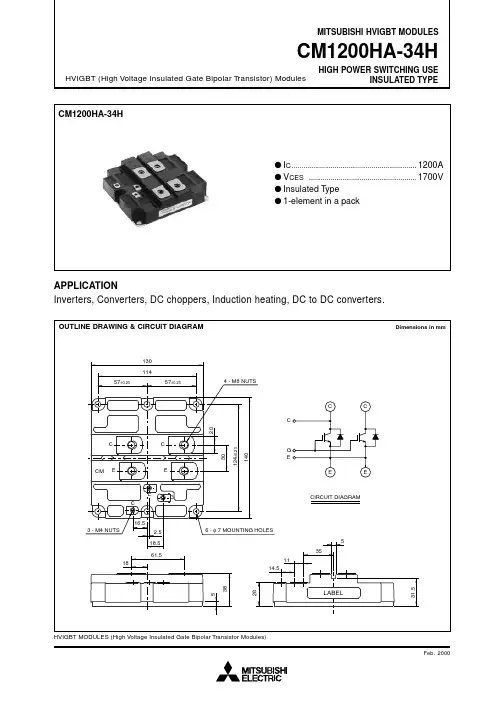
OUTLINE DRAWING & CIRCUIT DIAGRAMDimensions in mm3rd-Version HVIGBT (High Voltage Insulated Gate Bipolar Transistor) Modules
HVIGBT MODULES (High Voltage Insulated Gate Bipolar Transistor Modules)CIRCUIT DIAGRAMEC
EECC
EGC
LABELCEGC
ECMEECC
29.5
51361.561.5140
124±0.25
40
79.420.2557±0.25171190
5.2401541.2557±0.2557±0.25
38
2820
3 - M4 NUTS8 - φ7MOUNTING HOLES6 - M8 NUTS元器件交易网www.cecb2b.comPRELIMINARY
Notice: This is not a final specification.
Some parametric limits are subject to change.
Mar. 2003MITSUBISHI HVIGBT MODULES
CM2400HC-34H
HIGH POWER SWITCHING USE
INSULATED TYPE
V
VVCE = VCES, VGE = 0V
VGE = VGES, VCE = 0V
Tj = 25°C
Tj = 125°C
VCC = 850V, IC = 2400A, VGE = 15V
VCC = 850V, IC = 2400A
VGE1 = VGE2 = 15V
RG = 0.27Ω
Resistive load switching operation
IE = 2400A, VGE = 0V
IE = 2400A,
die / dt = –5800A / µs
Junction to case, IGBT part
Junction to case, FWDi part
Case to fin, conductive grease appliedIC = 240mA, VCE = 10V
IC = 2400A, VGE = 15V(Note 4)
VCE = 10V
VGE = 0VCollector cutoff current
Gate-emitter
threshold voltage
Gate-leakage current
Collector-emitter
saturation voltage
Input capacitance
Output capacitance
Reverse transfer capacitance
Total gate charge
Turn-on delay time
Turn-on rise time
Turn-off delay time
Turn-off fall time
Emitter-collector voltage
Reverse recovery time
Reverse recovery charge
Thermal resistance
Contact thermal resistanceCollector-emitter voltage
Gate-emitter voltage
Maximum collector dissipation
Junction temperature
Storage temperature
Isolation voltage
Mounting torque
MassVGE = 0V
VCE = 0V
DC, TC = 80°C
Pulse(Note 1)
Pulse(Note 1)
TC = 25°C, IGBT part
—
—
Charged part to base plate, rms, sinusoidal, AC 60Hz 1min.
Main terminals screw M8
Mounting screw M6
Auxiliary terminals screw M4
Typical valueCollector current
Emitter current1700
±20
2400
4800
2400
4800
17800
–40 ~ +150
–40 ~ +125
4000
6.67 ~ 13.00
2.84 ~ 6.00
0.88 ~ 2.00
1.5MAXIMUM RATINGS (Tj = 25°C)
Symbol ItemConditionsUnitRatings
V
V
A
A
A
A
W
°C
°C
V
N·m
N·m
N·m
kgVCES
VGES
IC
ICM
IE (Note 2)
IEM(Note 2)
PC (Note 3)
Tj
Tstg
Viso
—
—
MinTypMax
36
0.5
—
—
—
—
—
—
1.60
2.00
2.70
0.80
—
2.70
—
0.007
0.012
—mA
µA
nF
nF
nF
µC
µs
µs
µs
µs
V
µs
µC
K/W
K/W
K/W—
—
2.60
3.20
210
27.0
10.8
19.8
—
—
—
—
2.60
—
900
—
—
0.006—
—
—
—
—
—
—
—
—
—
—
—
—
—
—
—
—
—ICES
IGES
Cies
Coes
Cres
QG
td (on)
tr
td (off)
tf
VEC(Note 2)
trr (Note 2)
Qrr (Note 2)
Rth(j-c)Q
Rth(j-c)R
Rth(c-f)ELECTRICAL CHARACTERISTICS (Tj = 25°C)
SymbolItemConditions
VGE(th)
VCE(sat)Limits
Unit
5.54.5
Note1. Pulse width and repetition rate should be such that the device junction temp. (Tj) does not exceed Tjmax rating.
2. IE, VEC, trr, Qrr & die/dt represent characteristics of the anti-parallel, emitter to collector free-wheel diode.
3. Junction temperature (Tj) should not increase beyond 150°C.
4. Pulse width and repetition rate should be such as to cause negligible temperature rise.6.53rd-Version HVIGBT (High Voltage Insulated Gate Bipolar Transistor) Modules
HVIGBT MODULES (High Voltage Insulated Gate Bipolar Transistor Modules)元器件交易网www.cecb2b.com