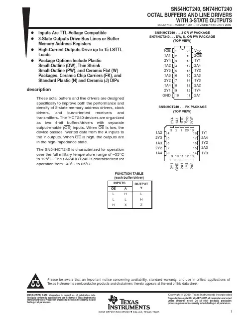
74VHC240_07资料
- 格式:pdf
- 大小:187.86 KB
- 文档页数:9
tm
74VHC240 Octal Buffer/Line Driver with 3-STATE Outputs
April 2007
©1992 Fairchild Semiconductor Corporationwww.fairchildsemi.com
74VHC240 Rev. 1.3
74VHC240
Octal Buffer/Line Driver with 3-STATE Outputs
Features
■
High Speed: t
PD
=
3.6ns (typ) at T
A
=
25°C
■
Low power dissipation: I
CC
=
4µA (max) @ T
A
=
25°C
■
High noise immunity: V
NIH
=
V
NIL
=
28% V
CC
(min.)
■
Power down protection is provided on all inputs
■
Low noise: V
OLP
=
0.9V (max.)
■
Pin and function compatible with 74HC240
General Description
The VHC240 is an advanced high speed CMOS octal
bus buffer fabricated with silicon gate CMOS technology.
It achieves high speed operation similar to equivalent
Bipolar Schottky TTL while maintaining the CMOS low
power dissipation. The VHC240 is an inverting 3-STATE
buffer having two active-LOW output enables. This
device is designed to drive buslines or buffer memory
address registers.
An input protection circuit ensures that 0V to 7V can be
applied to the input pins without regard to the supply
voltage. This device can be used to interface 5V to 3V
systems and two supply systems such as battery
backup. This circuit prevents device destruction due to
mismatched supply and input voltages.
Ordering Information
Surface mount packages are also available on Tape and Reel. Specify by appending the suffix letter “X” to the
ordering number. Pb-Free package per JEDEC J-STD-020B.
Connection DiagramPin Descriptions
Order NumberPackage
NumberPackage Description
74VHC240MM20B20-Lead Small Outline Integrated Circuit (SOIC), JEDEC MS-013, 0.300" Wide
74VHC240SJM20D20-Lead Small Outline Package (SOP), EIAJ TYPE II, 5.3mm Wide
74VHC240MTCMTC2020-Lead Thin Shrink Small Outline Package (TSSOP), JEDEC MO-153, 4.4mm
Wide
Pin NamesDescription
OE
1
, OE
2
3-STATE Output Enable Inputs
I
0
–I
7
Inputs
O
0
–O
7
Outputs 3-STATE Outputs元器件交易网www.cecb2b.com
74VHC240 Octal Buffer/Line Driver with 3-STATE Outputs
©1992 Fairchild Semiconductor Corporationwww.fairchildsemi.com
74VHC240 Rev. 1.32
Logic Symbol
IEEE/IEC
Truth Tables
H
=
HIGH Voltage Level
L
=
LOW Voltage Level
X
=
Immaterial
Z
=
High Impedance
InputsOutputs
OE
1
I
n
(Pins 12, 14, 16, 18)
LLH
LHL
HXZ
InputsOutputs
OE
1
I
n
(Pins 3, 5, 7, 9)
LLH
LHL
HXZ元器件交易网www.cecb2b.com
74VHC240 Octal Buffer/Line Driver with 3-STATE Outputs
©1992 Fairchild Semiconductor Corporationwww.fairchildsemi.com
74VHC240 Rev. 1.33
Absolute Maximum Ratings
Stresses exceeding the absolute maximum ratings may damage the device. The device may not function or be
operable above the recommended operating conditions and stressing the parts to these levels is not recommended.
In addition, extended exposure to stresses above the recommended operating conditions may affect device reliability.
The absolute maximum ratings are stress ratings only.
Recommended Operating Conditions
(1)
The Recommended Operating Conditions table defines the conditions for actual device operation. Recommended
operating conditions are specified to ensure optimal performance to the datasheet specifications. Fairchild does not
recommend exceeding them or designing to absolute maximum ratings.
Note:
1.Unused inputs must be held HIGH or LOW. They may not float.
Symbol Parameter Rating
V
CC
Supply Voltage –0.5V to +7.0V
V
IN
DC Input Voltage –0.5V to +7.0V
V
OUT
DC Output Voltage –0.5V to V
CC
+ 0.5V
I
IK
Input Diode Current –20mA
I
OK
Output Diode Current ±20mA
I
OUT
DC Output Current ±25mA
I
CC
DC V
CC
/GND Current ±75mA
T
STG
Storage Temperature –65°C to +150°C
T
L
Lead Temperature (Soldering, 10 seconds) 260°C
Symbol Parameter Rating
V
CC
Supply Voltage 2.0V to +5.5V
V
IN
Input Voltage 0V to +5.5V
V
OUT
Output Voltage 0V to V
CC
T
OPR
Operating Temperature –40°C to +85°C
t
r
, t
f
Input Rise and Fall Time,
V
CC
=
3.3V ± 0.3V
V
CC
=
5.0V ± 0.5V 0ns/V ∼ 100ns/V
0ns/V
∼
20ns/V元器件交易网www.cecb2b.com