比例流量控制阀 VPCF-6-L-8-G38-6-A4-E-EX2
- 格式:pdf
- 大小:112.90 KB
- 文档页数:2
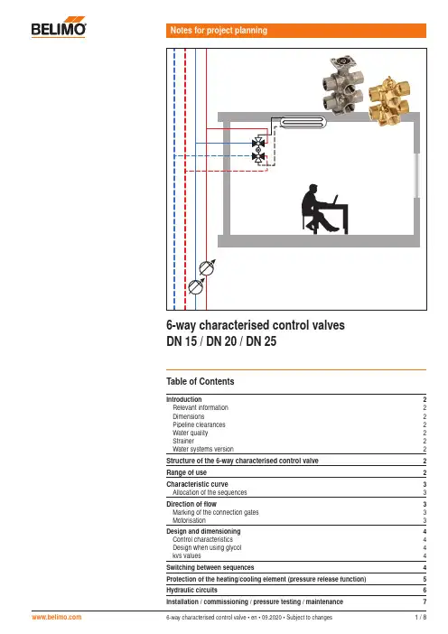
6-way characterised control valve • en • 09.2020 • Subject to changes1 / 8Table of ContentsIntroduction2Relevant information 2Dimensions2Pipeline clearances 2Water quality 2Strainer2Water systems version2Structure of the 6-way characterised control valve 2Range of use 2Characteristic curve 3Allocation of the sequences 3Direction of flow3Marking of the connection gates 3 Motorisation3Design and dimensioning 4Control characteristics 4Design when using glycol 4kvs values4Switching between sequences4Protection of the heating/cooling element (pressure release function) 5Hydraulic circuits6Installation / commissioning / pressure testing / maintenance72 / 86-way characterised control valve • en • 09.2020 • Subject to changes Structure of the 6-way characterised control valve456789231101112136-way characterised control valvesIntroductionRelevant informationThe data, information and limit values listed on the data sheet of the 6-way characterised control valve are to be taken into account and/or complied with, respectively.DimensionsThe dimension of the valve-actuator combination used is dependent not only on the nominal diameter of the valve but also on the actuator used. The dimensions are listed in the R30..-..-..-B.. data sheet.Pipeline clearancesThe minimum clearances between the pipelines and the walls and ceilings required for project planning depend not only on the valve dimensions but also on the selected actuator. The dimensions can be found on the R30..-..-..-B.. data sheet.Water qualityThe water quality requirements specified in VDI 2035 must be adhered to.Strainer6-way characterised control valves are regulating devices. The use of central strainers in the system is recommended in order to prolong their service life for performing control tasks.Water systems versionApplication is permissible only in closed water circuits.1 Connection flange2 Spindle3 Stem packing O-ring (EPDM)4 Closing element 1 with L-bore5 Closing element 2 with L-bore6 Valve seat (PTFE, O-ring EPDM)7 Characterised disc8 Supply sequence 1 connection *9 Return sequence 1 connection *10 Supply sequence 2 connection *11 Return sequence 2 connection *12 Supply heating/cooling element connection *13 Return heating/cooling element connection ** Internal thread according to ISO 7-1DN15: Rp ½", DN20: Rp ¾", DN25: Rp 1"Range of useThe 6-way characterised control valve has been specially developed for use with combined heating and cooling elements. A 6-way characterised control valve performs the function of four2-way valves or two 2-way valves and one changeover valve.H C EelementConventional solution with four 2-way valvesConventional solution with two 2-way valves and one changeover valveSolution with a6-way characterised control valveThe 6-way characterised control valve handles control of hot and cold water.189212111310R30..-..-..-B2/B3R3015-..-..-B1 6-way characterised control valve • en • 09.2020 • Subject to changes3 / 86-way characterised control valvesCharacteristic curveWhen the valve is rotated by 90°, these 3 sequences are run through.kValve tightly closedAllocation of the sequencesAllocation to hot and chilled water is in principle, freely selectable. However, due to installation safety, the definition of an equal allocation for all valves is recommended.!The following mandatory allocation is to be selected when the room temperature controller CRK24-B1 from Belimo is used, due to the control characteristics:Sequence 1 = cooling Sequence 2 = heatingDirection of flowThe direction of flow must be observed.Sequence 1Sequence 2100%Marking of the connection gatesThese are numbered from 1 to 6 for the purpose of secure allocation of the connections during planning and installation.Motorisation6-way characterised control valves are motorised with a rotary actuator. The control must be modulating.R3015-..-..-B1R30..-..-..-B2/B34 / 86-way characterised control valve • en • 09.2020 • Subject to changes 6-way characterised control valvesDesign and dimensioningControl characteristicsTo ensure a valve attains good control characteristics thus a long service life for the control element, it needs to be correctly designed with the correct valve authority.The valve authority av is the benchmark for the control characteristics of the valve in combination with the hydraulic network. The valve authority is the relation between the differential pressure of the fully open valve at nominal flow and the maximum differential pressure for the closed valve. The higher the valve authority, the better the control characteristics. The smaller the valve authority av becomes, the more the operational behaviour of the valve will deviate from the linearity i.e.. the poorer the volumetric flow control will be. In practice the intended av is >0.5.Design when using glycolTo reduce the freezing point of water, salt was added to the water in the past. These werecalled brine applications. Today glycol is used and we talk about cold agents. Depending on the concentration of the cold agent used (type of glycol) and the medium temperature, the density of the water/glycol mixture varies between 1 and 9 percent. The resultant volume deviation is less than the permissible volume tolerance of the valve's k vs value (by ±10 percent according to VDE 2178) and as a rule need not be taken into account even if glycol requires a slightly higher k v value.Depending on the type of glycol, compatibility with the valve materials used must be guaranteed and the permissible maximum concentration (50 percent) must not be exceeded.k vs valuesSince different k vs values are often required for heating and cooling, 6-way characterised control valves are available with different k vs values for sequences 1 and 2. For a full overview, see data sheet R30..-..-..-B.. .Using an additional flow limiterWhen using additional flow limiting valves (e.g. PIQCV C2..QP(T)-.. with manual flow rate setting) or an additional pressure-independent control valve (e.g. motorised PIQCV) atthe system level, it is not necessary to use the flow characterised disc in the 6-way valve in the system to reduce the k vs value. The differential pressure required for operation is kept as low as possible in this manner. In addition, possible noise generation in conjunction with the additional components used is avoided.DN15 max. k vs 0.63 m 3/h: DN15 max. k vs 1.8 m 3/h: DN20 max. k vs 4 m 3/h: DN25 max. k vs 6.3 m 3/h:R3015-P63-P63-B1 R3015-1P8-1P8-B2 R3020-4-4-B2 R3025-6P3-6P3-B3Switching between sequencesAs with all combined heating/cooling elements in 4-pipe systems, mass displacement can occur when using 6-way characterised control valves.Mass displacementWith each switch (from cooling to heating operation or from heating to cooling operation) water is displaced from one circuit to the other. Due to the different medium temperatures, the density of this water differs. Due to the constant volume in the heating/cooling element, the quantity of water displaced has a different mass. When switching from cooling to heating, more mass is shifted then when switching from heating to cooling. This mass displacement can lead to the cooling circuit being emptied.It is important to cater for this normal behaviour. For corresponding recommendations, see the chapter 'Hydraulic circuits'.MediaDue to the mass displacement that occurs, the medium in both circuits needs to have the same properties (glycol concentration). 6-way characterised control valve • en • 09.2020 • Subject to changes 5 / 86-way characterised control valvesProtection of the heating/cooling element (pressure release function)In cases of combined heating/cooling elements, the medium is enclosed in the element when they are in closed status (no heating or cooling). The pressure of the enclosed medium can rise or fall due to changes in medium temperature caused by the ambient temperature. The 6-way characterised control valve have an integrated pressure release function for the purpose of compensating for such pressure changes.Design for pressure releaseThe upper ball of the characterised control valve has a groove that forms a link between the 'Supply Sequence 1' (Gate 1) connection point and the heating/cooling element connected at Gate 2 when the valve is closed.Pressure release Groove for pressure releaseFunction means of the connection to the 'Sequence 1' circuit. No further flow of water takes place after the pressure compensation due to the same absolute pressures in Sequence 1, in the heating and cooling element and in the lower closing element, which closes air-bubble tight.Behaviour in hot or cold operationThe pressure relief function has no influence on the hot or cold operation. When operating sequence 1, the function is on the same side as the desired water flow. When operatingsequence 2, the pressure relief function is not active. A direct mixing of water of the sequences of 1 and 2 is not possible duration operation.k αControl sequence 1Position Valve closedControl sequence 21) Positioning signal for closed position:Operating range drive 2…10 V: Y = 6 Volt Operating range drive 0.5…10 V: Y = 5.25 VoltValve leakage rateEach water circuit is channeled through two valve cones (series circuit). As a result of the continued air-bubble tight closing of the lower closing element 2, the valve continues to exhibit Leakage rate A in accordance with EN 12266-1, even for Sequence 1.Equivalent circuit diagramPressure release6 / 86-way characterised control valve • en • 09.2020 • Subject to changes 6-way characterised control valvesHydraulic circuitsFor correct operation, the following planning instructions need to be complied with, among others:MediaThe medium in both circuits needs to have the same quality (glycol concentration).System pressureThe system pressures in the heating and cooling circuit must have the same value.Possible hydraulic circuitsIn a 4-pipe system with heating and cooling circuits, the effect of mass displacement always exists regardless of the valve used (see chapter on mass displacement). To cater for this behaviour and prevent mass displacement, there are various solutions and corresponding precautionary measures.1. Two expansion vessels– 2. One expansion vessel– One expansion vessel for both circuits. Connection point on the suction side of the pumps.– Pumps at the same height.– Connection line between heating circuit return and cooling circuit return.– The same static pressure on the suction side of the pumps.3. Two expansion vessels in a hydraulic coupling system– The same static pressure on the suction side of the pumps.– Pumps at the same height.– The 2-way valve remains closed during operation.– The 2-way valve will open if the pressures p Heating and p Cooling exhibit a certain difference due to the mass displacement.– The system pressures are balanced.– The 2-way valve is closed again after the compensation.6-way characterised control valve • en • 09.2020 • Subject to changes 7 / 86-way characterised control valvesInstallation/Commissioning/Pressure testing/MaintenanceValve positionThe ball position can be discerned by means of the marking on the top of the spindle.Valve delivery conditionThe valves are delivered ex works as shown with the picture below.Delivery condition conforms to valve position 90°/positioning signal 10 V.Delivery with valve installedFor visualisation purposes, the actuator has two green dots.Only valid for R30..-..-..-B2/B3R3015-..-..-B1 cannot be supplied with the actuator installed ex worksPressure testing Due to the built-in pressure release safety function, the following needs to be observed:Pressure testing with connected heating/cooling elementIf the connected consumer circuit is also to be tested, pressure testing can be performed without additional restrictions in valve positions 'Sequence 1 open' (angle of rotation 0°) or 'Sequence 2 open' (angle of rotation 90°).When tested in closed valve position (45°), note that the connected heating/cooling element is likewise pressurised with the pressure in sequence 1.Pressure testing without connected heating/cooling elementIn valve closed position (45°) the sequence 1 test medium flows via gates 1 and 2. Thisbehaviour does not constitute a malfunction since the valve closes both water circuits reliably due to the air-bubble tightness of the second closing element during operation.Possibilities:– Individual testing of water circuits1. Sequence 1 test with valve in 90° positionNote: Prior to switching, sequence 1 needs to be emptied. 2. Sequence 2 test with valve in 0° positionor– Additional isolation of gate 2Maintenance 6-way characterised control valves are maintenance-free.R3015-..-..-B1R30..-..-..-B2/B3All inclusive.Belimo worldwide: SwitzerlandBELIMO Automation AG Swiss SalesBrunnenbachstrasse 1CH-8340 HinwilTel. +41 (0)43 843 62 12Fax +41 (0)43 843 62 66****************www.belimo.ch。
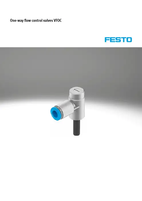
One-way flow control valves VFOCOne-way flow control valves VFOCProduct range overview – One-way flow control valves1)Standard nominal flow rate in flow control direction.2)Only suitable for push-in connector QS.2d Internet: /catalogue/...Subject to change – 2021/11One-way flow control valves VFOC Product range overview – One-way flow control valves1)Standard nominal flow rate in flow control direction.3 2021/11 – Subject to change d Internet: /catalogue/...One-way flow control valves VFOC Key featuresFunctionThe piston speed of both advancing and retracting pneumatic cylinders, can be regulated using one-way flow control valves. This is done through suitable restric-tion of the flow rate of compressed airin exhaust air or supply air direction.The non-return function works in theopposite direction.The flow control function creates anadjustable annular gap inside thevalve. This gap can be increased or de-creased by turning the knurled screwor slotted head screw.The required restriction can be set withthe help of this adjustment element.General informationStandard nominal flow rate qnN Standard flow rate qn Symbols ConnectionsThe standard nominal flow rate qnN is the volumetric flow rate based on standard conditions at an operating pressure of p1 = 6 bar and an output pressure of p2 = 5 bar, measured at room temperature t = 20°C.The standard flow rate qn is measuredat an operating pressure of p1 = 6 barand an output pressure with respect toatmospheric pressure (p2 = 0 bar).Exhaust air one-way flow controlfunctionSupply air one-way flow controlfunction2[1] Pneumatic connection 1(compressed air connection)[2] Pneumatic connection 2 (workingport)4d Internet: /catalogue/...Subject to change – 2021/11One-way flow control valves VFOCType codes52021/11 – Subject to change d Internet: /catalogue/...6d Internet: /catalogue/...Subject to change – 2021/11One-way flow control valves VFOCDatasheetOne-way flow control function -M- Flow rate 0 ... 270 l/min -Q- Temperature range –10 ... +60°C -L-Operating pressure0.2 ... 10 barStandard nominal flow rate qnN at 6 a 5 bar as a function of spindlerotations nStandard flow rate qn at 6 a0 bar as a function of spindle rotations nQS-6QS-4QS-6QS-4Supply airOne-way flow control valves VFOC DatasheetMaterialsSectional view7 2021/11 – Subject to change d Internet: /catalogue/...。
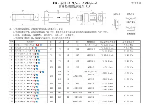
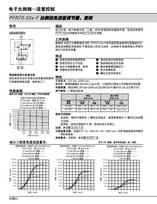
注:1.管路防爆限速阀,是按用户提供的技术参数设计、定制。
3.尾缀:-01液压油,-02磷酸酯,-03天然气,-04乳化液,-05煤油等。
4.管路防爆(限速)阀,接口1与油缸连接,接口2与高压软管连接。
2.管路限速阀型号:在限速流量后加‘XS'字样,要求管路爆裂后油缸缓慢回落的在卸载流量后加‘XZ’字样。
D.管路防爆限速阀关闭后,流体通过旁路卸载,其最大卸载流量≤油缸最E.管路防爆限速阀关闭后,流体通过旁路限速,其最大限速流量≤油缸最 大工作流量的 20 %,在限速流量后加‘XS'字样,如:FBF16M27×2·B·40Z·6XS -01如:FBF16M27×2·B·40Z·2XZ -01,参数确定参看附表!B.管路防爆限速阀关闭流量,取值范围在(1.3A~1.8A)L/min。
限速流量 D~E,即:(0.01A~0.2A)L/min,参数商榷备案。
注:A.油缸的最大工作流量或管路可以通过的最大流量。
C.管路防爆限速阀在管路爆裂后关闭无泄漏,油缸被锁死。
大工作流量的 5 %,在卸载流量后加‘XZ'字样,7.管路防爆限速阀,型号的蓝色数字是系统介质代码,按系统介质改写。
5.管路防爆限速阀,型号的红色数字是油缸的最大工作流量或管路可以通过的最大流量,需按系统参数改写,其值≤该型号允许值,见附表。
6.最大工作流量值加注压力代码,如工作压力>20MPa用“G ”表示,<20MPa用“Z ”,<10MPa用“D ”,<5MPa用“CD ”,<2.5MPa 无注,见附表!说明1.阀体用材料:45#优质碳素结构钢。
FBF·A50~A150·B……系列管路防爆限速阀与 ISO 6164-2大通径高压法兰对接,工作压力25MPaFBF—系列 与 LB型防爆阀接口尺寸及参数对照表(以下型号多配置在外贸型工业电炉)FBF·系列(0.2L/min~6500L/min)管路防爆限速阀选型(4)附表Q/FBF4-01复位。
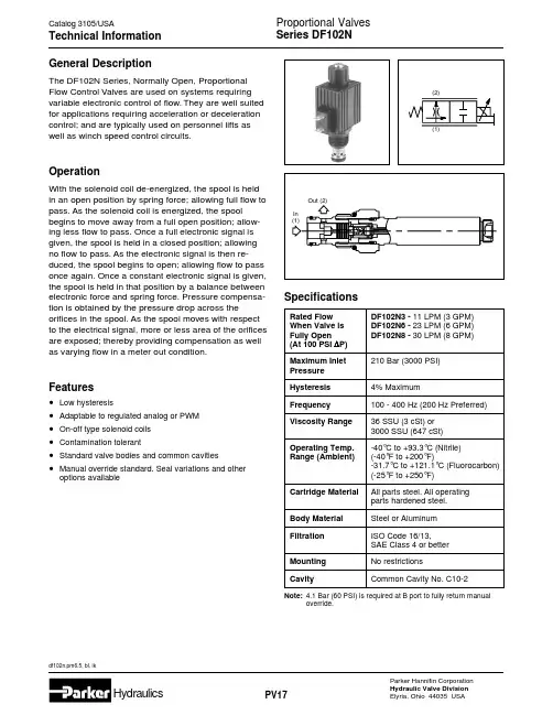
Out (2)SpecificationsRated FlowWhen Valve isFully Open(At 100 PSI ∆P)Maximum InletPressureHysteresisFrequencyViscosity RangeOperating Temp.Range (Ambient)Cartridge MaterialBody MaterialFiltrationMountingCavity4.1 Bar (60 PSI) is required at B port to fully return manualoverride.Performance CurvesSolenoid Coil SpecificationsResponse Time Within Regulating Zone35ms Wire Class “H ” for all voltagesVoltage 10VDC 12VDC 18VDC 24VDC 36VDC 48VDC Duty STD.HD.STD.HD.STD.HD.STD.HD.STD.HD.STD.HD.Watts (Nominal)173017301730173017301730Amps1.583.201.442.300.941.860.721.200.430.880.300.58Hydraulic Oil 135 SSU @ 100°F (28 cSt)P r e s s u r e D r o p (P )∆Flow (Q)349113236GPM45125715Pressure Drop vs.FlowHydraulic Oil 135 SSU @ 100°F (28 cSt)515573820F l o w (Q )10Percent of Rated Amperage @ 200 Hz (PWM)60204080100Flow vs.InputDF102N8(30W Coil)DF102N6(17W Coil)DF102N3(17W Coil)Hydraulic Oil 135 SSU @ 100°F (28 cSt)15F l o w (Q )510Pressure1402000701000355001051500PSI17525002103000Flow Regulation vs.PressureSeries DF102NDimensionsSeries DF102NOrdering Information2Type10SizeDFProportional Flow ControlValve7/8-14UNF-2B Threaded CavitySealsCode Type Omit Nitrile VFluorocarbonOverride Option******calls out voltage. For example: 851023-012VDC is a 12 volt, 17 watt DC Double Wire coil.Coil Assemblies851017******17 Watt Conduit Coil 851018******30 Watt Conduit Coil 851019******17 Watt DIN(Hirschmann) Coil 851020******30 Watt DIN(Hirschmann) Coil851021******17 Watt Double Spade Coil 851022******30 Watt Double Spade Coil851023******17 Watt Double Wire Coil 851024******30 Watt Double Wire Coil 851025******17 Watt Single Screw Coil 851026******30 Watt Single Screw Coil 851027******17 Watt Single Wire Coil 851028******30 Watt Single Wire CoilFlow OptionBody OptionCoil VoltageCoil TerminationMTwo Position,Two Way SpoolCode DescriptionOmitCartridge Without Coil C 1/2″ NPTF Conduit Connector with 24″ Class H Wire D DIN 43650(Hirschmann) Plug Face P SAE 1B-0.25 SAE Double Spade (DC Only)S1Single 8-32 screw & nut internally ground (DC Only)W Double wire 24″ Class H (DC Only)W1Single wire, internally ground,24″ Class H (DC Only)Code TypeOmit Cartridge Without Coil D01010 VDC D01212 VDC D01818 VDC D02424 VDC D03636 VDC D04848 VDCCode Type MPush TypeManual Override with Flush RodCode Description N3Normally Open11 LPM (3 GPM) @100 ∆P with 17W Coil N6Normally Open23 LPM (6 GPM) @100 ∆P with 17W Coil N8Normally Open30 LPM (8 GPM) @100 ∆P with 30W CoilCode Port Size & MaterialOmit Cartridge Only 4P 1/4″ NPTF (B10-2-4P)SteelA4P1/4″ NPTF (B10-2-A4P)Aluminum 6P 3/8″ NPTF (B10-2-6P)SteelA6P 3/8″ NPTF (B10-2-A6P)Aluminum 8P 1/2″ NPTF (B10-2-8P)SteelA8P1/2″ NPTF (B10-2-A8P)Aluminum 6TSAE-6(B10-2-6T)SteelA6T SAE-6(B10-2-A6T)Aluminum 8T SAE-8(B10-2-8T)SteelA8T SAE-8(B10-2-A8T)Aluminum4B 1/4″ BSPG (B10-2-4B)SteelA4B 1/4″ BSPG (B10-2-A4B)Aluminum 6B 3/8″ BSPG (B10-2-6B)SteelA6B 3/8″ BSPG (B10-2-A6B)Aluminum 8B 1/2″ BSPG (B10-2-8B)SteelA8B1/2″ BSPG (B10-2-A8B)AluminumCoil WattageCode Wattage Omit Cartridge without Coil L 17 Watt H 30 WattSERVICE PARTSNitrile Seal Kit: SK10-2Coil Nut: 118113-00Fluorocarbon Seal Kit: SK10-2V DIN Connector:Grey - 692914Black - 692915Shipping Weight Cartridge Only .32 kg (0.7 lbs.)Cartridge in Body .77 kg (1.7 lbs.)。
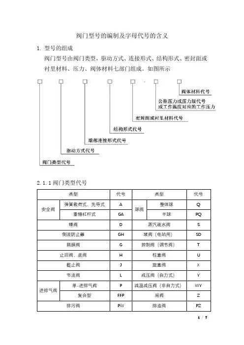
阀门型号的编制及字母代号的含义1.型号的组成阀门型号由阀门类型,驱动方式、连接形式、结构形式、密封面或衬里材料、压力、阀体材料七部门组成。
如图所示1.2.1.1阀门类型代号类型代号类型代号安全阀弹簧载荷式、先导式 A球阀整体球Q 重锤杠杆式GA 半球PQ 蝶阀 D 蒸汽疏水阀S 倒流防止器GH 堵阀(电站用)SD 隔膜阀G 控制阀(调节阀)T 止回阀、底阀H 柱塞阀U 截止阀J 旋塞阀X 节流阀L 减压阀(自力式)Y进排气阀单-进排气阀P 减温减压阀(非自力式)WY 复合型FFP 闸阀Z 排污阀PW 排渣阀PZ2.1.2当阀门又同时具有其他功能作用或带有其他结构时,在阀门类型代号前再加注一个汉语拼音字母、典型功能代号按下表规定。
2.2驱动方式代号驱动方式代号用阿拉伯数字表示,按下表规定。
4.3连接形式代号以阀门进口端的连接形式确定代号,代号用阿拉伯数字表示,按下表规定。
4.4阀门结构形式代号阀门结构形式用阿拉伯数字表示,按下列表规定。
4.4.2截止阀和节流阀结构形式代号4.4.3止回阀结构形式代号4.4.5蝶阀结构形式代号4.4.6旋塞阀结构形式代号4.4.7隔膜阀结构形式代号4.4.8减压阀(自力式)结构形式代号4.4.9控制阀(调节阀)结构形式代号4.4.9减温减压阀(非自力式)结构形式代号4.4.10堵阀结构形式代号4.4.11蒸汽疏水阀结构形式代号4.4.12排污阀结构形式代号4.4.13安全阀结构形式代号4.5密封副或衬里材料代号密封副或衬里材料代号,以两个密封面中起密封作用的密封面材料或衬里材料硬度值较低的材料或腐蚀性较低的材料表示;金属密封面中镶嵌非金属材料的,则表示为非金属/金属。
材料代号按下表规定的字母表示。
4.6压力代号压力级代号采用 PN 后的数字表示。
4.7阀体材料代号。
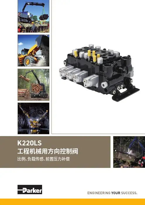
2工程机械用方向控制阀K220LS样本MSG17-8537/CN派克汉尼汾公司移动液压系统欧洲事业部Borås, Sweden样本布局除一般信息和基本技术数据外,该样本还对K220LS 可配置的选配功能做了描述。
我们可据此对K220LS 进行定制配置,以符合您的需求。
多路阀的每个功能区域都有一个副标题,标题后面附有简短的描述。
如果某个功能区有多个不同的位置,则会在副标题的方括号内标注位置编号,例如[P16]溢流阀。
再接下来是一系列带有代号的选项,例如PA1、Y 以及每个代号的简短描述。
或者是一个或多个压力、流量或电压选项。
位置编号也可参见配置代号报告和备件清单。
第8页的一般液压回路图中展示了K220LS 阀的基本功能区、以及代表这些功能区的条目编号。
多路阀订购方式我们开发并推出了配置K220LS 阀的软件。
这个软件也能给您生成阀技术文档,其中会包含详细的阀代号报告、3D 模型、2D 图纸、备件清单和液压原理图。
软件还会创建一个唯一的ID 号,并印在阀产品标签上。
您的阀配置会保存在我们的数据库中,以便查询服务或重新订购时快速确定。
样本信息销售要约请联系您的派克销售代表,获取详细的“销售要约”。
专业建议,以节约时间和成本我们的工程师经验丰富,他们对不同类型的液压系统及其工作原理都有深入的了解。
他们可随时为您提供专业的建议,按您需要的方式将各种机器功能、控制特性和价格要求完美组合在一起。
建议在项目规划阶段尽早咨询派克,为您设计一个完整的液压系统,使您的机器达到理想的操作和控制特性。
派克保留修改产品的权利,恕不另行通知。
本样本中使用了典型的曲线和图表。
即使样本不断修订和更新,也不可避免存在出错的可能。
请联系派克汉尼汾,了解更多有关产品的详细信息。
3工程机械用方向控制阀K220LS样本MSG17-8537/CN派克汉尼汾公司移动液压系统欧洲事业部Borås, Sweden目录目录页码概述....................................................................................................................4技术数据 ............................................................................................................5[P03-P09]概述 ................................................................................................6-7液压原理图 .....................................................................................................8-9进口片 ..............................................................................................................10[P10-P29] 进口片 .......................................................................................10[P12] 内部先导压力供油 ...........................................................................11[P13] 先导压力...........................................................................................11[P14] 先导过滤器.......................................................................................11[P15] 进口片类型.......................................................................................11[P16] 溢流阀...............................................................................................12[P17] 压力设定...........................................................................................12[P20] 负载信号复制阀芯 ...........................................................................13[P24] 回油口T2 ..........................................................................................14[P25] 回油口T1 ..........................................................................................14[P26] 进油口P1 ..........................................................................................14[P28] 用于先导回路的单独回油口............................................................14出口片 ..............................................................................................................15[P30 - P44] 出口片 .....................................................................................15[P31] 油口 ..................................................................................................15[P32] 进油口P2 ..........................................................................................15[P34] 回油口T3 ..........................................................................................15[P40] 先导回路回油口 ...............................................................................15工作片 ..............................................................................................................16[P45-P89] 工作片 .......................................................................................16[P47] 连接油口...........................................................................................16[P50] 阀芯执行器.......................................................................................17PC/PCH 液压阀芯执行器 .....................................................................17ECS2/EC2/ECH2 电液阀芯执行器 .......................................................18[P51] 手柄支架...........................................................................................19[55A, B] 先导节流口...................................................................................20[P56] 插头类型...........................................................................................20[P59] 阀芯执行器变型 ...............................................................................20[P60-P74] 阀芯选择 ...................................................................................21[P60] 阀芯功能...........................................................................................21[P64A, B] 力反馈 ........................................................................................22[P66] 压力补偿器和负载保持单向阀........................................................23[P69] 阀芯名称...........................................................................................24[P71A, B] 工作油口公称流量.....................................................................24[P72] 流量设定...........................................................................................24[P74] 工作片变型.......................................................................................24[P75] 进给减压阀.......................................................................................25[P75A] [P75B] 设定油口A 和B 的进给减压 ................................................25[P76A, B] 溢流阀和防气穴阀.....................................................................26[P85] 侧油口连接.......................................................................................26[P89A, B] 工作油口变型 ............................................................................26[P90-P99] 功能阀块 ...................................................................................27附件 ............................................................................................................27信息..................................................................................................................28[P50] EC2 手动越权 ...................................................................................28尺寸图 ..............................................................................................................29备件..................................................................................................................30[P00]指客户规格中的项目编号。
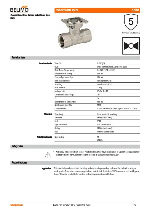
B220B•ApplicationChrome Plated Brass Ball and Nickel Plated Brass StemTechnical dataFunctional dataValve Size 0.75" [20]Fluidchilled or hot water, up to 60% glycol Fluid Temp Range (water)0...250°F [-18...120°C]Body Pressure Rating 600 psi Close-off pressure ∆ps 200 psiFlow characteristic equal percentage Servicing maintenance-free Flow Pattern 2-way Leakage rate0% for A – AB Controllable flow range 75°Cv14 Body pressure rating note 600 psi No Characterized Disc TRUECv Flow RatingA-port: as stated in chart B-port: 70% of A – AB Cv MaterialsValve body Nickel-plated brass body Stem seal EPDM (lubricated)SeatPTFEPipe connection NPT female ends O-ring EPDM (lubricated)Ballchrome plated brass Suitable actuatorsNon-SpringTR LRB(X)Safety notesWARNING: This product can expose you to lead which is known to the State of California to cause cancer and reproductive harm. For more information go to Product featuresThis valve is typically used in air handling units on heating or cooling coils, and fan coil unit heating or cooling coils. Some other common applications include Unit Ventilators, VAV box re-heat coils and bypass loops. This valve is suitable for use in a hydronic system with variable flow.B220B Flow/Mounting detailsDimensionsDimensional drawingsLRB, LRXA B C D E F H1H29.4" [239] 2.7" [69] 5.8" [147] 5.1" [129] 1.3" [33] 1.3" [33] 1.2" [30]1" [25]TRA B C D E F4.0" [102] 2.7" [69]5.4" [137] 5.1" [129] 1.3" [33] 1.3" [33]TFRB, TFRXA B C D E F7.0" [178] 2.7" [69] 5.5" [139] 4.8" [122] 1.5" [39] 1.5" [39]LFA B C D E F8.6" [218] 2.7" [69] 6.3" [159] 5.6" [142] 1.8" [46] 1.8" [46]A B C D E F8.6" [218] 2.7" [69] 6.3" [159] 5.6" [142] 1.8" [46] 1.8" [46]B220BTFRB, TFRXA B C D E F7.0" [178] 2.7" [69] 5.5" [139] 4.8" [122] 1.5" [39] 1.5" [39]LRB24-3-T•••••On/Off, Floating Point, Non-Spring Return, 24 VTechnical dataElectrical dataNominal voltageAC/DC 24 V Nominal voltage frequency 50/60 Hz Power consumption in operation 1.5 W Power consumption in rest position 0.2 WTransformer sizing 2.5 VA (class 2 power source)Electrical Connection Screw terminal (for 26 to 14 GA wire)Overload Protectionelectronic thoughout 0...90° rotation Functional dataInput Impedance 600 ΩDirection of motion motor selectable with switch 0/1Manual override external push button Angle of rotation 90°Angle of rotation note adjustable with mechanical stop Running Time (Motor)90 s Noise level, motor 35 dB(A)Position indicationMechanically, pluggable Safety dataDegree of protection IEC/EN IP54Degree of protection NEMA/UL NEMA 1 UL Enclosure Type 1Agency Listing cULus acc. to UL60730-1A/-2-14, CAN/CSA E60730-1:02, CE acc. to 2014/30/EU Quality Standard ISO 9001Ambient temperature -22...122°F [-30...50°C]Storage temperature -40...176°F [-40...80°C]Ambient humidity max. 95% r.H., non-condensing Servicingmaintenance-free WeightWeight1.1 lb [0.50 kg]Safety notes3/8”-16 shaft clevis for AHK/AH.Battery Back Up System for SY(7~10)-1105/16” shaft clevis for LH.Cable to ZIP-RS232 US to diagnostic/programming socket.MFT95 resistor kit for 4 to 20 mA control applications.Electrical installationINSTALLATION NOTESProvide overload protection and disconnect as required.Actuators may be connected in parallel. Power consumption and input impedance must be observed.Actuators may also be powered by 24 VDC.LRB24-3-TActuators Hot wire must be connected to the control board common. Only connect common to neg. (-) legof control circuits. Terminal models (-T) have no-feedback.Actuators are provided with a numbered screw terminal strip instead of a cable.Meets cULus requirements without the need of an electrical ground connection.Warning! Live Electrical Components!During installation, testing, servicing and troubleshooting of this product, it may be necessary to workwith live electrical components. Have a qualified licensed electrician or other individual who has beenproperly trained in handling live electrical components perform these tasks. Failure to follow all electricalsafety precautions when exposed to live electrical components could result in death or serious injury.On/Off Floating PointFloating Point - Triac Source Floating Point - Triac Sink。
订货量(个) 价格(含运费)≥1850.00元/个成为该供应商会员可享受折优惠.请登录后进行申请•发货地:湖北武汉江汉区运费:卖家承担运费•商品满意度:暂无评价•可用保障金:¥14000.00(详细说明)诚保支持先行赔付,保障买家采购的资金,运费等安全,查看详情。
•交易方式:支持担保交易支持保障金安全交易点此抽奖,赢手机!类型比例阀材质碳钢型号BYM-E10B 品牌武汉大通适用范围注塑机适用介质油品适用温度65(℃)公称压力31.5(MPa)公称通径10(mm)安装形式板式工作温度常温类型(通道位置)直通式连接形式板式驱动方式电磁电磁溢流阀和比例溢流阀功能上区别不是太大,都是在系统压力超过设定值时开启卸压、溢流;不同的是,比例溢流阀可以按比例调定溢流的流量,对系统的控制更加精密。
普通的溢流阀就是开启和关闭两个位置,比例阀在开启溢流时可以有多个位置。
1:以输入电流线性控制压力和流量,达到最优功率配置。
为执行元件提供必须的最小压力和流量。
2:可根据负载压力,以压差保持最小值控制泵的压力,是一种低能耗的调速阀。
3:此阀具有温度补偿功能,能使所控制流量稳定而不受油液温度的影响。
1:安装位置:正确的安装位置是使放气孔朝上以便试车时排出油路中空气。
若遇到阀必须垂直安装时,订货时请特别说明。
2:空气排除:将圆后盖朝上的放气孔螺丝打开(请将系统压力调在30bar)让空气排出,当阀内充满油不再见气泡后,将螺丝再锁紧。
3:手动调压螺丝:当电气控制发生故障时,而临时需要压力供应,此刻可将手动调整螺丝顺时针旋入即可;平时则复归原位。
4:回油管路:回油背压尽量低,油管末端直接插入油面之下。
避免管路曲折或有限流现象。
5:最高安全压力设定:依实际油泵流量及实际使用压力而决定,通常在油泵流量100/min以下时,追加15bar即可。
A概述阀对流量的控制可以分为两种:一种是开关控制:要么全开、要么全关,流量要么最大、要么最小,没有中间状态,如普通的电磁直通阀、电磁换向阀、电液换向阀。
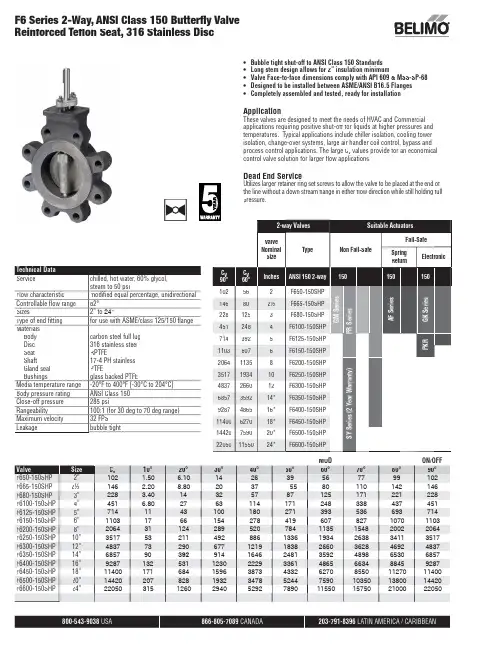
800-543-9038 866-805-7089 203-791-8396Technical Data Servicechilled, hot water, 60% glycol, steam to 50 psi Flow characteristic modifi ed equal percentage, unidirectional Controllable fl ow range 82°Sizes2” to 24"Type of end fi tting for use with ASME/class 125/150 fl angeMaterials Body Disc Seat ShaftGland seal Bushingscarbon steel full lug 316 stainless steel RPTFE17-4 PH stainless PTFEglass backed PTFEMedia temperature range -20°F to 400°F [-30°C to 204°C]Body pressure rating ANSI Class 150Close-off pressure 285 psiRangeability100:1 (for 30 deg to 70 deg range)Maximum velocity 32 FPS Leakagebubble tight•Bubble tight shut-off to ANSI Class 150 Standards •Long stem design allows for 2” insulation minimum• Valve Face-to-face dimensions comply with API 609 & MSS-SP-68•Designed to be installed between ASME/ANSI B16.5 Flanges •Completely assembled and tested, ready for installationApplicationThese valves are designed to meet the needs of HVAC and Commercial applications requiring positive shut-off for liquids at higher pressures and temperatures. Typical applications include chiller isolation, cooling tower isolation, change-over systems, large air handler coil control, bypass and process control applications. The large C v values provide for an economical control valve solution for larger fl ow applications.Dead End ServiceUtilizes larger retainer ring set screws to allow the valve to be placed at the end of the line without a down stream fl ange in either fl ow direction while still holding full pressure.MOD ON/OFF ValveSize C v 10°20°30°40°50°60°70°80°90°F650-150SHP 2”102 1.50 6.10142639567799102F665-150SHP 2½”146 2.208.8020375580110142146F680-150SHP 3”228 3.4014325787125171221228F6100-150SHP 4”451 6.802763114171248338437451F6125-150SHP 5”7141143100180271393536693714F6150-150SHP 6”1103176615427841960782710701103F6200-150SHP 8”2064311242895207841135154820022064F6250-150SHP 10”35175321149288613361934263834113517F6300-150SHP 12”483773290677121918382660362846924837F6350-150SHP 14”685790392914164624813592489865306857F6400-150SHP 16”92871325311230222933614865663488459287F6450-150SHP 18”11400171684159638734332627085501127011400F6500-150SHP 20”144202078281932347852447590103501380014420F6600-150SHP 24”22050315126029405292789011550157502100022050F6 Series 2-Way, ANSI Class 150 Butterfl y Valve Reinforced Tefl on Seat, 316 Stainless Disc2-way ValvesSuitable ActuatorsValve Nominal SizeType Non Fail-SafeFail-SafeSpring Return Electronic C v90°C v 60°Inches ANSI 150 2-way 150150150102562F650-150SHPG M S e r i e sP R S e r i e sA F S e r i e sG K S e r i e s146802½F665-150SHP2281253F680-150SHP 4512484F6100-150SHP 7143925F6125-150SHP P K R 11036076F6150-150SHP 206411358F6200-150SHP S Y S e r i e s (2 Y e a r W a r r a n t y )3517193410F6250-150SHP 4837266012F6300-150SHP 6857359214*F6350-150SHP 9287486516*F6400-150SHP 11400627018*F6450-150SHP 14420759020*F6500-150SHP 220501155024*F6600-150SHP866-805-7089 203-791-8396 LATIN AMERICA / CARIBBEANMaximum Dimensions (Inches)F650-150SHP 2”102 1.759.009.0019.50 4.7545/8-11 UNC 2*AF150Spring Return F665-150SHP 2½”146 1.889.009.0020.00 5.5045/8-11 UNC 150F680-150SHP 3”2281.929.009.0020.50 6.0045/8-11 UNC 150F6100-150SHP4”451 2.139.009.0021.007.5085/8-11 UNC 150F650-150SHP 2”102 1.759.009.0019.50 4.7545/8-11 UNC GK 285Electronic Fail-Safe F665-150SHP 2½”146 1.889.009.0020.00 5.5045/8-11 UNC 285F680-150SHP 3”228 1.929.009.0020.50 6.0045/8-11 UNC 285F6100-150SHP 4”451 2.139.009.0021.007.5085/8-11 UNC 150F6100-150SHP 4”4512.139.009.0021.007.5085/8-11 UNC 2*GK 285F650-150SHP2”102 1.759.009.0019.50 4.7545/8-11 UNC GM 285Non-Spring Return Electronic Fail-Safe (K)F665-150SHP 2½”146 1.889.009.0020.00 5.5045/8-11 UNC 285F680-150SHP 3”228 1.929.009.0020.50 6.0045/8-11 UNC 285F6100-150SHP 4”451 2.139.009.0021.007.5085/8-11 UNC 150F6100-150SHP 4”451 2.139.009.0021.007.5085/8-11 UNC 2*GM285F650-150SHP 2”1021.7510.0015.0014.00 4.7545/8-11 UNC PR/PK285F665-150SHP2½”146 1.8810.0016.0014.00 5.5045/8-11 UNC 285F680-150SHP 3”2281.9210.0017.0015.00 6.0045/8-11 UNC 285F6100-150SHP4”451 2.1310.0018.0016.007.5085/8-11 UNC 285F6125-150SHP 5”7142.2510.0019.0016.008.5083/4-10 UNC 285F6150-150SHP6”1103 2.2910.0020.0017.009.5083/4-10 UNC 285F6200-150SHP 8”20642.5012.0012.0032.0011.7583/4-10 UNC SY4…285F6250-150SHP 10”3517 2.8112.0012.0033.0014.25127/8-9 UNC SY4…285F6300-150SHP 12”4837 3.2312.0012.0035.0017.00127/8-9 UNC SY4…150SY5…285F6350-150SHP 14”6857 3.6214.0014.0036.0018.75121-8 UNC SY5…150SY7…285150F6400-150SHP 16”9287 4.0014.0014.0037.5021.25161-8 UNC SY8…285F6450-150SHP 18”11400 4.5014.0014.0042.2522.7516 1 1/8-8 UNC SY7…150SY8…285F6500-150SHP 20”14420 5.0014.0014.0049.5025.0020 1 1/8-8 UNC SY8…150SY10…285F6600-150SHP24”220506.0614.0014.0056.2529.50201 1/4-8 UNCSY10…150F6 Series 2-Way, ANSI Class 150 Butterfl y ValveReinforced Tefl on Seat, 316 Stainless DiscDimension “A” does not include flange gaskets. (2 required per valve)Application Notes1. Valves are rated at 285 psi differential pressure in the closed position @ 100°F media temperature.2. V alves are furnished with lugs tapped for use between ANSI Class 125/150fl anges conforming to ANSI B16.5 Standards.3. 2-way assemblies are furnished assembled, calibrated and tested, ready for installation.4. D imension “D” allows for actuator(s) removal without the need to remove the valve from the pipe.5. W eather shields are available, dimensional data furnished upon request.6. F lange gaskets (2 required, not provided with valve) MUST be used between valve and ANSI fl ange.7. F lange bolts are not included with the valve. These are furnished by others.DB CABHCSHP seriesvalves have a preferred flow direction.P r e f e r r e d F l o w r a t eModulating, Electronic Fail-Safe, 24 V, for DC2...10 V or 4...20 mA Control SignalTechnical dataElectrical data Nominal voltage AC/DC 24 VNominal voltage frequency50/60 HzPower consumption in operation12 WPower consumption in rest position 3 WTransformer sizing40 VA (class 2 power source)Electrical Connection18 GA plenum cable with 1/2" conduitconnector, degree of protection NEMA 2 / IP54,3 ft [1 m] 10 ft [3 m] and 16ft [5 m]Overload Protection electronic throughout 0...95° rotationFunctional data Options positioning signal variable (VDC, on/off, floating point)Position feedback U variable VDC variableBridging time programmable 0...10 s (2 s default) delaybefore fail-safe activatesPre-charging time 5...20 sDirection of motion motor selectable with switch 0/1Direction of motion fail-safe reversible with switchManual override external push buttonAngle of rotation Max. 95°, max. 95°, adjustable with mechanicalstopAngle of rotation note max. 95°, adjustable with mechanical stopRunning Time (Motor)default 150 s, variable 95...150 sRunning time motor variable95...150 sRunning time fail-safe<35 sNoise level, motor52 dB(A)Noise level, fail-safe61 dB(A)Position indication Mechanically, 30...65 mm strokeSafety data Degree of protection IEC/EN IP54Degree of protection NEMA/UL NEMA 2Enclosure UL Enclosure Type 2Agency Listing cULus acc. to UL60730-1A/-2-14, CAN/CSAE60730-1:02, CE acc. to 2014/30/EU and2014/35/EU; Listed to UL 2043 - suitable for usein air plenums per Section 300.22(c) of the NECand Section 602.2 of the IMCQuality Standard ISO 9001Ambient temperature-22...122°F [-30...50°C]Storage temperature-40...176°F [-40...80°C]Ambient humidity Max. 95% RH, non-condensingServicing maintenance-freeMode of operationProduct featuresSY9~12 Replacement HandwheelAccessoriesGatewaysDescriptionType Gateway MP to BACnet MS/TP UK24BAC Gateway MP to LonWorks UK24LON Gateway MP to Modbus RTUUK24MOD Electrical accessoriesDescriptionType Feedback potentiometer 10 kΩ add-on, grey P10000A GR Feedback potentiometer 1 kΩ add-on, grey P1000A GR Feedback potentiometer 140 Ω add-on, grey P140A GR Feedback potentiometer 2.8 kΩ add-on, grey P2800A GR Feedback potentiometer 5 kΩ add-on, grey P5000A GR Feedback potentiometer 500 Ω add-on, grey P500A GR Auxiliary switch 1 x SPDT add-on S1A Auxiliary switch 2 x SPDT add-onS2A Service Tool, with ZIP-USB function, for programmable andcommunicative Belimo actuators, VAV controller and HVAC performance devicesZTH USService toolsDescriptionTypeConnection cable 10 ft [3 m], A: RJ11 6/4 ZTH EU, B: 3-pin Weidmüller and supply connectionZK4-GEN Service Tool, with ZIP-USB function, for programmable and communicative Belimo actuators, VAV controller and HVAC performance devicesZTH USElectrical installationINSTALLATION NOTESActuators with appliance cables are numbered.Provide overload protection and disconnect as required.Actuators may also be powered by DC 24 V.Only connect common to negative (-) leg of control circuits.A 500 Ω resistor (ZG-R01) converts the 4...20 mA control signal to 2...10 V.Control signal may be pulsed from either the Hot (Source) or Common (Sink) 24 V line.For triac sink the Common connection from the actuator must be connected to the Hotconnection of the controller. Position feedback cannot be used with a triac sink controller; theactuator internal common reference is not compatible.IN4004 or IN4007 diode. (IN4007 supplied, Belimo part number 40155).Actuators may be controlled in parallel. Current draw and input impedance must be observed.Master-Slave wiring required for piggy-back applications. Feedback from Master to controlinput(s) of Slave(s).Meets cULus requirements without the need of an electrical ground connection.Warning! Live electrical components!During installation, testing, servicing and troubleshooting of this product, it may be necessary to work with live electrical components. Have a qualified licensed electrician or other individual who has been properly trained in handling live electrical components perform these tasks. Failure to follow all electrical safety precautions when exposed to live electrical components could result in death or serious injury.Wiring diagramsOn/Off Floating PointVDC/mA Control PWM Control。
One-way flow control valves VFOFOne-way flow control valves VFOFKey features and product range overview Key features• Minimal height• High flow rate• Can be rotated horizontally by 360° in assembled state• Universal actuation direction [1] by converting the housing• More functionality – Function combi-nationsH--NoteWhen assembling the individual components, please note the follow-ing sequence as follows:1) Press thrust ring [2] into thehousing for a positive fit.2) Insert hollow bolt [3] into theopening.3) Slide sealing ring OK [4] over thethread of the hollow bolt.1) Standard nominal flow rate in flow control direction.2d I nternet: /catalogue/...Subject to change – 2023/08One-way flow control valves VFOF, function combinationType codes32023/08 – Subject to change d I nternet: /catalogue/...4d I nternet: /catalogue/...Subject to change – 2023/08One-way flow control valves VFOF, function combinationDatasheetOne-way flow control function Exhaust air-M- Standard nominal flow rate 240 ... 590 l/min -Q- Temperature range –10 ... +60°C -L-Operating pressure0.2 ... 10 barThe one-way flow control valve VFOF-LE-BAH is a valve with a function com -bination consisting of an exhaust air one-way flow control function and a pi -loted non-return function with manual exhaust function.The exhaust air one-way flow control function is used for manually adjustingthe speed at which the piston rod of a pneumatic drive advances/retracts.The flow control function is realised by an adjustable annular gap in the hous -ing. This gap can be increased or de -creased by turning the adjusting screw with internal hex.The piloted non-return function can be used for a temporary intermediate stop. If a control signal is applied, the exhaust air flow control takes effect. If no control signal is applied, the valve shuts off the exhaust air from the drive and the drive stops temporarily.By actuating the integrated manual ex -haust function, it is possible to manu -ally exhaust the pneumatic drive.G1/41)More information /x/topic/crc52023/08 – Subject to change d I nternet: /catalogue/...One-way flow control valves VFOF, function combinationDatasheetMaterialsSectional view Standard nominal flow rate qnN in flow control direction at 6 > 5 bar as a function of turns of the adjusting screw n Standard flow rate qn in flow control direction at 6 > 0 baras a function of turns of the adjusting screw n VFOF-LE-BAH/VBNF-LBA nq n N [l /m i n ]12345678910100200300400500600VFOF-LE-BAH/VBNF-LBAnq N [l /m i n ]12345678910100200300400500600700800900VFOF-…-G18-Q6VFOF-…-G14-Q8Flow rate value tolerance: ±20%VFOF-…-G18-Q6VFOF-…-G14-Q8Flow rate value tolerance: ±20%Minimum pilot pressure p21 as a function of operating pressure p1VFOF-LE-BAH/VBNF-LBAp1[bar]p 21[b a r ]123456789100123456451One-way flow control valves VFOF, function combinationDatasheet1)Unactuated6d I nternet: /catalogue/...Subject to change – 2023/08Festo - Your Partner in AutomationConnect with us/socialmedia 1Festo Inc.2Festo Pneumatic 3Festo Corporation 4Regional Service Center 5300 Explorer DriveMississauga, ON L4W 5G4CanadaAv. Ceylán 3,Col. Tequesquináhuac 54020 Tlalnepantla, Estado de México1377 Motor Parkway Suite 310Islandia, NY 117497777 Columbia Road Mason, OH 45040Festo Customer Interaction CenterTel:187****3786Fax:187****3786Email:*****************************Multinational Contact Center 01 800 337 8669***********************Festo Customer Interaction Center180****3786180****3786*****************************S u b j e c t t o c h a n g e。
规格精度: ±(读数的0.8% + 满量程的0.2%)重复性: 满量程的±0.2% 量程比:100:1控制响应时间: 100 ms输入控制信号: 0 ~ 5 Vdc, RS232输出信号: 0 ~ 5 Vdc, RS232可选输入/输出: 4 ~ 20 mA , 0 ~ 10 Vdc 工作温度: 10 ~ 50°C (14 ~ 50.00°C)零点偏移: 满量程的0.02%/°C 量程偏移: 满量程的0.02%/°C 湿度量程: 0 ~ 100% RH ,无冷凝附加流速: 满量程的2.4%接液材质:303和302不锈钢、氟橡胶、硅酮RTV (橡胶)、玻璃强化型尼龙、铝、铜、410不锈钢、硅酮、玻璃;>250SLM :416不锈钢和镍替换铜最大压力质量流量控制器: 145 psig使用体积模式: 使用体积模式:近大气,建议最大15 psig 。
体积流量计和控制器不保证超出流量计额定流量范围的质量流速的准确性。
这些值仅适用于近大气压力条件。
建议最大工作压力为15 psigD-29U 20多种气体校准,包括氦气、氧气、氖气、一氧化二氮、氮气、大气、氩气、一氧化碳、二氧化碳、甲烷、乙烷、氢气、丙烷、丁烷、异丁烷、乙烯、乙炔、氪气、氙气、六氟化硫U 同时显示压力、温度、体积以及质量流量 U 简单易用的按钮界面U NIST 可溯源性标准U 满量程范围:0.5 SCCM ~ 3000 SLM U 常规响应时间:50 ~ 100 毫秒U 常规量程比:100:1U 位置不敏感U ±0.8%读数精度U 标配RS232FMA-2600A 系列质量与体积流量控制器在层流场中使用差压原则来确定和控制质量流速。
流量计中的层流元件(LFE)迫使气体进入层流。
泊肃叶方程规定, 在这一区域体积流速与压力下降呈线性关系。
使用压差传感器衡量LFE 固定距离中的压力下降情况。