牛!大河工业居然有专用共享单车电子锁自动焊锡机
- 格式:docx
- 大小:349.53 KB
- 文档页数:7
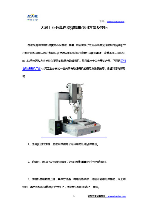
大河工业分享自动焊锡机使用方法及技巧在选择自动焊锡机时首先不仅要选,要看,然后购买了之后必须要合理的规范各种细节才能把焊锡机器人的寿命延长,在使用自动焊锡机的时候也是需要掌握一些基本技巧和方法的,这些技巧和方法能让你更快的熟悉自动焊锡机,并且焊出十分完美的产品。
下面是深圳自动焊锡机厂家-大河工业分享的一些关于自动焊锡机的使用方法及技巧,希望对您有所帮助1、选用合适的焊锡,应选用焊接电子组件用的低熔点焊锡丝。
2、助焊剂,用25%的松香溶解在75%的酒精(重量比)中作为助焊剂。
3、焊锡机使用前要上锡,具体方法是:将电烙铁烧热,待刚刚能熔化焊锡时,涂上助焊剂,再用焊锡均匀地涂在烙铁头上,使烙铁头均匀的吃上一层锡。
4、焊锡机焊接方法,把焊盘和组件的引脚用细砂纸打磨干净,涂上助焊剂。
用烙铁头沾取适量焊锡,接触焊点,待焊点上的焊锡全部熔化并浸没组件引线头后,电烙铁头沿着元器件的引脚轻轻往上一提离开焊点。
5、焊锡机焊接时间不宜过长,否则容易烫坏组件,必要时可用镊子夹住管脚帮助散热。
6.选择合理的焊接顺序。
以减小焊接变形、焊枪行走路径长度来制定焊接顺序。
7.焊枪空间过渡要求移动轨迹较短、平滑、安全。
8.优化焊接参数。
为了获得最佳的焊接参数,制作工作试件进行焊接试验和工艺评定。
自动焊锡机在效率和精度上已经遥遥领先于手工焊锡,即使是一位技艺精湛的焊锡师傅也不能像自动化设备一样,可以长时间的高精度、高强度的持续进行焊锡工作,由于人工焊接会对身体产生危害,那么,我们可以使用自动焊锡机来代替手工,还给工作人员一个健康的身体!自动焊锡机,全程自动化,无需经手人工,确保质量与产量共同提高,买焊锡机就来深圳大河工业设备有限公司大河工业地址:深圳市宝安区松岗街道学生工业园路7号2栋大河工业官网:。
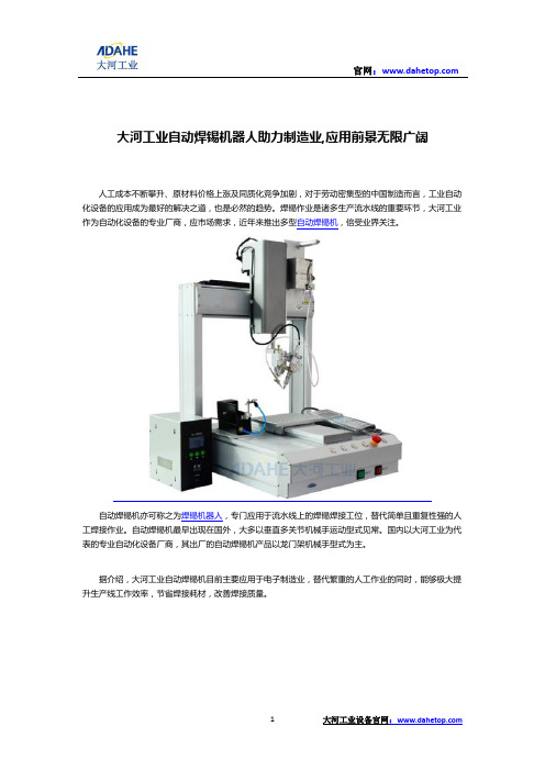
大河工业自动焊锡机器人助力制造业,应用前景无限广阔人工成本不断攀升、原材料价格上涨及同质化竞争加剧,对于劳动密集型的中国制造而言,工业自动化设备的应用成为最好的解决之道,也是必然的趋势。
焊锡作业是诸多生产流水线的重要环节,大河工业作为自动化设备的专业厂商,应市场需求,近年来推出多型自动焊锡机,倍受业界关注。
自动焊锡机亦可称之为焊锡机器人,专门应用于流水线上的焊锡焊接工位,替代简单且重复性强的人工焊接作业。
自动焊锡机最早出现在国外,大多以垂直多关节机械手运动型式见常。
国内以大河工业为代表的专业自动化设备厂商,其出厂的自动焊锡机产品以龙门架机械手型式为主。
据介绍,大河工业自动焊锡机目前主要应用于电子制造业,替代繁重的人工作业的同时,能够极大提升生产线工作效率,节省焊接耗材,改善焊接质量。
大河工业自动焊锡机可根据客户实际需求,定制灵活多样的焊锡方式。
与此同时,大河工业自动焊锡机支持点焊和拖焊(拉焊),所有的工艺参数均可由用户自行进行设置,以适应各种高难度作业和微焊锡工艺。
所有焊锡参数都可以伴随焊点坐标程序读取和保存,实现焊锡作业的柔性化,而这也是大河工业自动焊锡机倍受客户青睐的优势所在。
柔性生产是制造业近些年比较热门的词汇,亦是未来发展的方向。
大河工业焊锡机具有生产柔性的特征,在实际生产中能够很好地满足产品多样化生产的需求,解放枯燥重复岗位的劳动人员,帮助生产流程更加高效、快速。
据了解,仅一台大河工业自动焊锡机,便可支持近百种产品的焊锡作业。
自动焊锡机从属于工业自动化设备的一种,纵观整个世界,我国自动焊锡机发展起步较晚,但目前已不乏大河工业为代表的,拥有核心技术优势的一大批研发企业。
比尔·盖茨曾说过,机器人将重复个人电脑崛起的道路,成为下一个改变世界的技术。
就目前来看,其应用的深度与广度已成为衡量一个国家制造业水平和科技水平的重要标志。
这也是工业自动化设备近年来高速发展的重要驱动因素。
90后这一代不同于他们的父辈,大多不愿接受重复性的流水线工作。

全自动焊锡机控制系统用户手册版权说明本手册未经本公司书面许可,任何人或组织不得翻印、翻译和抄袭。
本手册中的信息资料仅供参考。
由于改进设计和功能等原因,本公司保留对本资料的最终解释权,内容如有更改,恕不另行通知。
调试设备要注意安全!用户必须在设备中设计有效的安全保护装置,否则所造成的损失,本公司没有义务或责任负责。
目录系统概述 (3)一.欢迎界面 (3)二.主界面 (3)三.手动操作 (8)四.I/O调测 (9)五.参数设置 (10)5.1速度设置 (11)5.2限位设置 (12)5.3零点设置 (13)5.4其它设置 (13)5.5当量设置 (15)5.6密码设置 (15)5.7复位设置 (16)5.8工艺设置 (17)六.档案管理 (18)七.档案编程 (21)7.1空移 (23)7.2点焊 (23)7.3侧焊 (25)7.4焊接起点 (26)7.5拖焊 (27)7.6等待输入 (28)7.7输出 (28)7.8暂停 (29)7.7延时 (30)7.8旋转定位 (31)7.9循环 (32)7.10条件跳转 (34)7.11输出等待 (35)7.13矩阵 (36)7.14档案调用 (37)7.15程序结束 (37)八.报警 (38)九.调机指引 (42)步骤 (42)系统概述本系统适用于各类焊锡机,具有自动送锡功能,可扩展至双工位。
一.欢迎界面见图1.1。
触摸该界面可以进入主界面。
图1.1二.主界面进入到系统主界面,见图2.1。
主界面用于自动加工时的界面显示以及待机模式下档案操作和设备调试。
图2.11,格式为:当前档案号/总档案数,当前档案号表示正在执行的档案,总档案数表示系统中存在的总档案个数。
当前档案号可以直接输入选择档案。
2,档案名称对应当前档案号,选择当前档案号后,档案名称将自动更新显示。
3,格式为:当前步序/总步序数,当前步序为当前档案正在执行或将要执行的步序,总步序数为当前档案总的步序数。

组合自动焊技术嘿,朋友们!今天咱来聊聊组合自动焊技术,这可真是个了不起的玩意儿啊!你想想看,以前焊接那得靠人工,师傅们拿着焊枪,小心翼翼地操作,还得担心质量不稳定啥的。
可现在有了组合自动焊技术,那就大不一样啦!就好像是给焊接工作找了个超级厉害的助手。
组合自动焊技术就像是一个精准的舞者,在钢铁的舞台上尽情展现它的技艺。
它能快速、准确地完成焊接任务,而且质量那叫一个高啊!这可比人工焊接靠谱多了呀!你说要是没有这技术,那得费多大的劲儿呀!它的好处可多了去了。
首先呢,速度快得惊人,眨眼间就能把焊缝给搞定了,这效率,谁能不爱呢?然后呢,焊接的质量那是杠杠的,焊缝又结实又漂亮,就跟艺术品似的。
再说说它的适应性,那也是超强的哟!不管是啥形状的工件,它都能轻松应对,就像个万能钥匙一样,啥锁都能开。
而且啊,它还特别稳定,不会像人一样有时候会累了或者走神了,它始终都能保持最佳状态。
你说这组合自动焊技术是不是很厉害?这就好比是一个烹饪大师,不管是什么食材,都能做出美味佳肴来。
它让焊接工作变得简单、高效、可靠。
咱再打个比方,要是把焊接比作一场战斗,那组合自动焊技术就是那最厉害的武器,能让我们在这场战斗中轻松取胜。
有了它,我们就不用再担心焊接质量不过关,不用再担心效率低下啦!朋友们,你们想想看,要是所有的焊接工作都能用上组合自动焊技术,那该多好啊!那我们的工业生产得提升多少个档次呀!这可不是我在这儿瞎吹,这是实实在在的好处呀!所以说呀,组合自动焊技术真的是我们的好帮手,是焊接领域的大明星!它让我们的生活变得更加美好,让我们的工业发展更加迅速。
我们可得好好利用它,让它发挥出最大的作用,为我们创造更多的价值!怎么样,你们是不是也和我一样,对组合自动焊技术充满了期待呢?。

自动焊锡机原理
自动焊锡机是一种用于焊接电子元器件的设备,它能够实现自动化的焊接过程,提高生产效率,保证焊接质量。
其原理主要包括焊锡机构、控制系统和供锡系统三个部分。
首先,焊锡机构是自动焊锡机的核心部件,它包括焊锡头、焊锡台和焊锡枪。
焊锡头是焊锡机的执行部件,它通过控制系统的指令,完成焊锡动作。
焊锡台是焊接工件的支撑平台,它能够固定工件并提供稳定的工作环境。
焊锡枪是焊锡机的供锡装置,它能够将焊锡丝送入焊锡头,实现焊接作业。
其次,控制系统是自动焊锡机的大脑,它包括程序控制器、传感器和执行器。
程序控制器是焊锡机的核心控制单元,它能够接收操作指令,控制焊锡头的动作。
传感器能够实时监测焊接过程中的温度、压力和位置等参数,确保焊接质量。
执行器是控制系统的执行部件,它能够根据程序控制器的指令,驱动焊锡头和焊锡枪完成焊接动作。
最后,供锡系统是自动焊锡机的供锡装置,它包括锡丝供给装置、锡丝预热装
置和锡丝切断装置。
锡丝供给装置能够将焊锡丝送入焊锡枪,保证焊接过程中的锡丝供应。
锡丝预热装置能够提前加热焊锡丝,提高焊接速度和质量。
锡丝切断装置能够根据需要切断焊锡丝,确保焊接的准确性和稳定性。
总的来说,自动焊锡机通过焊锡机构、控制系统和供锡系统的协同作用,能够
实现自动化的焊接过程,提高生产效率,保证焊接质量。
它在电子制造行业中扮演着重要的角色,为电子产品的生产提供了可靠的焊接解决方案。

设计方案2024-03-28目录第一部分公司简介 ....................................................... 错误!未定义书签。
第二部分系统介绍 ....................................................... 错误!未定义书签。
1、概述.............................................................................................................. 错误!未定义书签。
2、系统结构...................................................................................................... 错误!未定义书签。
3、安能闸机通道三辊闸优势............................................................................ 错误!未定义书签。
4、系统功能特点.............................................................................................. 错误!未定义书签。
5、硬件介绍...................................................................................................... 错误!未定义书签。
5.1、智能读卡部分....................................................................................... 错误!未定义书签。
Enterprise Development专业品质权威Analysis Report企业发展分析报告哈工好烤克(昆山)智能设备有限公司免责声明:本报告通过对该企业公开数据进行分析生成,并不完全代表我方对该企业的意见,如有错误请及时联系;本报告出于对企业发展研究目的产生,仅供参考,在任何情况下,使用本报告所引起的一切后果,我方不承担任何责任:本报告不得用于一切商业用途,如需引用或合作,请与我方联系:哈工好烤克(昆山)智能设备有限公司1企业发展分析结果1.1 企业发展指数得分企业发展指数得分哈工好烤克(昆山)智能设备有限公司综合得分说明:企业发展指数根据企业规模、企业创新、企业风险、企业活力四个维度对企业发展情况进行评价。
该企业的综合评价得分需要您得到该公司授权后,我们将协助您分析给出。
1.2 企业画像类别内容行业空资质空产品服务:货物进出口;技术进出口(依法须经批准的项1.3 发展历程2工商2.1工商信息2.2工商变更2.3股东结构2.4主要人员2.5分支机构2.6对外投资2.7企业年报2.8股权出质2.9动产抵押2.10司法协助2.11清算2.12注销3投融资3.1融资历史3.2投资事件3.3核心团队3.4企业业务4企业信用4.1企业信用4.2行政许可-工商局4.3行政处罚-信用中国4.4行政处罚-工商局4.5税务评级4.6税务处罚4.7经营异常4.8经营异常-工商局4.9采购不良行为4.10产品抽查4.11产品抽查-工商局4.12欠税公告4.13环保处罚4.14被执行人5司法文书5.1法律诉讼(当事人)5.2法律诉讼(相关人)5.3开庭公告5.4被执行人5.5法院公告5.6破产暂无破产数据6企业资质6.1资质许可6.2人员资质6.3产品许可6.4特殊许可7知识产权7.1商标7.2专利7.3软件著作权7.4作品著作权7.5网站备案7.6应用APP7.7微信公众号8招标中标8.1政府招标8.2政府中标8.3央企招标8.4央企中标9标准9.1国家标准9.2行业标准9.3团体标准9.4地方标准10成果奖励10.1国家奖励10.2省部奖励10.3社会奖励10.4科技成果11土地11.1大块土地出让11.2出让公告11.3土地抵押11.4地块公示11.5大企业购地11.6土地出租11.7土地结果11.8土地转让12基金12.1国家自然基金12.2国家自然基金成果12.3国家社科基金13招聘13.1招聘信息感谢阅读:感谢您耐心地阅读这份企业调查分析报告。
单头双平台焊锡机操作规程引言单头双平台焊锡机是一种常用的自动化焊接设备,广泛应用于电子制造行业。
为了确保焊接质量和操作安全,制定本操作规程以规范焊锡机的使用。
一、操作准备1.将焊锡机放置在稳固平整的工作台上,并接通电源。
2.检查焊锡机的各部件是否完好,如有损坏或异常应及时维修或更换。
3.根据焊接工艺要求,选择合适的焊锡丝,并放入焊锡机的焊锡丝架中。
4.根据焊接工艺要求,调整焊锡机的温度、速度和时间设置。
二、操作步骤1.打开焊锡机的电源开关,待机器启动完成后,进入操作界面。
2.将需要焊接的电子元件准确放置在焊锡机的焊接工作台上,确保其位置正确。
3.在操作界面上输入焊接参数,如温度、速度和时间等。
4.根据焊接要求,选择合适的焊接模式,如波峰焊、波动焊或拖焊等。
5.按下开始按钮,焊锡机开始自动焊接。
操作时要注意不要干扰焊锡机的运行。
6.焊接完成后,焊锡机会自动停止工作,根据需要进行下一次焊接,重复步骤3-5。
7.如果需要更换焊锡丝,先关闭焊锡机的电源开关,然后更换焊锡丝,并重新调整焊锡机的参数。
8.结束操作时,关闭焊锡机的电源开关。
三、操作安全注意事项1.在操作焊锡机时,应戴上防护手套和眼镜,以避免热焊接物或烟雾对皮肤和眼睛的伤害。
2.在更换焊锡丝或进行维修时,应先关闭焊锡机的电源开关,避免电击和烫伤。
3.注意焊锡机周围的安全距离,并保持工作区域整洁,避免杂物阻碍焊锡机的运行。
4.焊锡机操作过程中,不得随意翻动焊锡丝架和其他部件,以免发生意外伤害。
5.若发现焊锡机有异常情况,如异响、烟雾或操作界面显示异常等,应立即停止使用,并联系维修人员进行排查和修理。
四、维护保养1.定期清洁焊锡机的焊接工作台、焊锡丝架和其他部件,以保持其表面清洁,并防止焊锡丝堆积。
2.定期检查焊锡机的连接线和电源线路,确保其良好连接和绝缘。
3.定期检查焊锡机的温度传感器、电机和其他关键组件的工作状态,如有故障应及时维修或更换。
4.成立维修保养小组,定期对焊锡机进行全面的维护保养工作,及时修复或更换老化的零部件。
ELECTRIC WINCH RATING*RESULT DOUBLE LINE OPERATIONModels SA7000and SA12000are factory equipped with a pulley block and hook and 50'of cable for double line operation.This increases the pulling capacity of the winch as shown,however,care must be taken to allow adequate motor cooling.Note that with double line,a pull of 25'requires reeling in 50'of cable.For intermittent use only.Ratings at left are based on 10'pull.For longer pulls motor cooling periods must be allowed.CONTINUOUS RUN TIME 4MINUTES CAUTION:CONTINUOUS RUNNING IN OF 4MINUTES WILL DAMAGE WINCH GUIDE TO ROLLING LOAD CAPACITY**APPROXIMATE LOAD SPEED(**)All capacities shown are with 15'of cable on the reel and 10%rolling friction factor.For full reel of cable adjust capacities according to graph above.Note 5%incline is one-half foot rise in ten feet.WINCH RATINGSMANUALMODELS SA5000,SA7000SA9000,SA12000500045004000350030002500200015001000500D E A D W E I G H T C A P A C I T Y (L B S .)*LENGTH OF CABLE ON REEL (FT.)1020304050S A 9000s i n gl e l i neS A12000d o u bl e li n eS A 7000d o u bl e l i n eS A 5000s i n g l e l i neUSED AS A HOIST FOR SUPPORTING OR PEOPLE OR LOADS OVER AREAS WHERE PEOPLE COULD BE PRESENT!E N G L I S HE S P A ÑO LF R A N ÇA I S1WARNING:FAILURE TO READ AND FOLLOW INSTRUCTIONS BELOW COULD RESULT IN OR FATAL INJURY.NOT TO BE USED AS A HOIST FOR LIFTING,SUPPORTING,OR TRANSPORT-PEOPLE OR LOADS OVER AREAS COULD BE PRESENT.winch is not designed for movement of beings.Do not use for scaffolding,or any other application in which persons could be positioned on or under the load at any time.Do not use as an overhead hoist.the manufacturer before using this in any vertical lifting/lowering applica-Tel.402-462-4141,Fax 402-460-4613.E-Mail **************************electric winch should be respected as equipment.High forces are created using a winch,creating potential safety hazards.Never allow children or anyone who is not familiar with the operation of the winch to use it.exceed rated winch load.high forces can be created if load being moved is too large or is allowed to get in a bind,etc.Note that installing longer than normal cable results in increased load on winch.If overloaded,this winch has power enough to break the cable.is equipped with a high-quality aircraft capable of handling the rated winch Never exceed the rated capacity.Do not use vehicle pulling power to increase the pulling capacity of your winch.When cable breakage occurs under tension,the cable tends to whip toward the winch area.It is recommended that a blanket or rug be placed over the cable during winching oper-ations to minimize this whipping action in case of cable breakage.apply load to winch with cable fully Keep at least three turns of cable the reel.the winching area free of all unneces-personnel.Never stand between load winch.12volt D.C.winches operate from a low D.C.source of power (e.g.,a car or battery).DO NOT connect winch to 120V A.C.power.winching operation has been complet-do not depend on the winch to support load.Always secure the load properly.tie down straps or chains.auxiliary handle is provided for emer-use only.Never use the auxiliary han-as an assist to the motor when the motor is running.Always remove the auxiliary han-dle when it is not in use.Do not operate the winch motor or allow the winch to free wheel the handle installed.hands and fingers clear of the drum cable area of the winch when operating.not attempt to guide the cable by hand it rewinds on the drum.winch must be securely attached to a member or frame that is capable sustaining loads in excess of the winch capacity.When attaching the winch to a vehicle,make sure the mounting pad area is rigidly supported by the vehicle frame.Always block the wheels to prevent vehicle from rolling when pulling a load with the releasing a load with the clutch,main-control of the speed.Excess speed result in winch damage and serious personal injury.21.Be sure that the mounting surface is of sufficientstrength to support a load well in excess of the rated winch capacity.2.Fasten the winch to the trailer winch stand (or othermounting surface)with three 1/2"bolts,nuts,wash-ers and lock washers.Be sure that the winch is posi-tioned so that the cable does not rub the front open-ing of the winch.3.On boat trailer installations the winch stand shouldbe adjusted so that the loading ring on the bow of the boat is at the same height or slightly higher than the winch drum when the boat is fully loaded on the trail-er.Be sure that the trailer-bow stop is located far enough back of the winch drum so that the cable hook is not drawn into the drum when the boat is fully loaded on the trailer.4.For double line use,install an eyehook on the winchstand close to the base of the winch for fastening the stationary cable hook.(see Fig.1)Be sure the eye-hook is of sufficient strength to withstand loads in excess5.Your thebasefor use with quick mountingshoulder studs,if desir-able.(See FIG.2&3)If you wish to use quick mount studs,they should be mounted securely into the winch stand.After positioning the winch on the studs,a 3/8"bolt should be placed in one of the other holes available to keep the winch securely in position.The wiring harness is designed to remain in the trunk of the car when not in use.This prevents tampering,acci-dent or misuse since the harness is needed to operate the winch electrically.These installation instructions provide ready access for use,yet allow the complete harness to be quickly removed if desired.1.Feed positive lead (long)wire only through any con-venient access hole inside the car trunk.It may be necessary to remove a knockout plug or rubber grommet from the trunk floor.It may also be neces-sary to remove the circuit breaker assembly from the positive wire in order to feed the wire under the car.2.Pull the positive lead wire along the underside of thecar into the engine compartment and up to the bat-tery.Fasten the wire to the car undercarriage with existing wiring clamps and brackets,making sure wire is not located near the exhaust system,or any hot or moving parts.Wire should be fastened secure-ly and without slack.Excess wire should remain in the trunk.3.Fasten the circuit breaker to the positive (+)batteryterminal (if nut and bolt type)or to the battery side of the starter solenoid.4.Attach negative wire to vehicle frame using a 1/4"bolt and locknut.Make sure you have a clean,tight connection.NOTE:If winch is to be mounted in front of vehicle,cut harness to the length needed making sure,if spliced,the splice is tight and well insulated.Attach ground as described in 4above.1.With the wires at the bottom,push the switch into thepocket in the winch housing.The switch should push easily to the bottom of the pocket and excess force should not be required for installation or removal of the switch.Be sure that the wires are free to rotate with the switch so that it will return to its center “off”position when released.Leave your car engine run-ning on fast idle as a precaution in case the battery is not in top condition.2.With the clutch lever in the engaged gears posi-tion,you may power the winch in either the load or unload direction.Allowing the switch to return to the OFF position will automatically stop the winch and lock the load in position.NOTE:It is normal for smoke to be produced during the initial power down use.WARNING:EVEN THOUGH THE WINCH IS EQUIPPED WITH CIRCUIT BREAKER OVERLOAD PROTECTION,PARTICULAR CARE SHOULD BE TAKEN NOT TO CREATE AN OVERLOAD.PAY ATTENTION TO THE SOUND OF THE WINCH AND THE LOAD BEING PULLED.MAKE CERTAIN THAT THE CABLE TENSION DOES NOT RISE SUDDEN-LY BECAUSE OF A BIND IN THE LOAD.CAUTION:The electric motor is designed for intermittent service only.Extended use without cooling off periods will cause overheating result-ing in motor damage.Maximum recommended continuous run time is four minutes.3.Slots are available in the switch handle for the attach-ment of a remote lanyard if desirable.This allows operation of the winch at a distance by pulling on the lanyard to rotate the switch.4.When the unit is used to trailer a boat,secure theboat onto the trailer with appropriate bow and tran-som tie down straps or chains.With the boat fullyHARNESS INSTALLATIONUNDER POWERBASE HOLE PATTERN (SA5000&SA7000)BASE HOLE PATTERN (SA9000&SA12000)FIG.2FIG.1FIG.33secured on the trailer,it is advisable to relieve the tension on the winch cable to avoid damage to the winch and trailer due to high shock loads encoun-tered when traveling.5.Always disconnect the switch when the winching operation is complete.Never leave the switch con-nected to the winch when not in use.1.The clutch lever provides a means for releasing aload without power while maintaining control of thespeed and provides for free wheeling so that cablecan be removed from the winch by hand.The clutchlever is spring loaded so that it returns to theengaged position when released.The lever will,however,remain in the free wheeling position ifrotated completely forward to free wheel.2.In order to release a load without power,rotate theclutch lever slowly and carefully forward toward“Free Wheel.”When the load begins to move,it canbe controlled by the clutch lever.Careful,slowmovement of the lever will provide smooth control ofthe load.WARNING:ALWAYS MAINTAIN CONTROL OFTHE LOAD.ALLOWING EXCESS SPEED COULDRESULT IN WINCH DAMAGE AND SEVERE PER-SONAL INJURY.3.Remember that the gear train and brake mechanismare completely disengaged in the“Free Wheel”posi-tion and in order to power the winch or hold a loadin position,the lever must be allowed to return to the“Engaged Gears”position.NOTE:It is not necessary to turn the clutch levercompletely to the“Engaged Gears”position manual-ly.The spring tension built into the winch providesadequate force on the clutch lever.CAUTION:Never force clutch lever in eitherdirection.1.An emergency crank handle is provided for use inthe event of a power failure.Remove the electricalpower from the winch.WARNING:NEVER OPERATE THE WINCH ELEC-TRICALLY WITH THE EMERGENCY HANDLE INPOSITION.2.Remove the plastic plug from the side of the winchhousing and insert the handle so that it completelyengages with the drive shaft.The handle can becranked in either direction with the clutch in theengaged position.To make cranking easier,theclutch can be placed in the free wheel position whileholding onto the emergency handle.WARNING:IF THE CLUTCH IS PLACED IN FREEWHEEL FOR HAND CRANKING,BE SURE TOMAINTAIN A FIRM GRIP ON THE HANDLE ATALL TIMES.Because the emergency crank handle for modelsSA9000and SA12000attaches to the clutch side of thewinch,it is equipped with a spring operated clip whichwill be depressed by the clutch handle in the free wheelposition when cranking in a clockwise direction toretrieve the cable.This clip is a safety feature and will re-engage the clutch mechanism in the event that the oper-ator loses control of on the winch.(See FIG.4)FEATUREHANDLE ONETWO TURNS BEFORE RE-ENGAGING THETO STOP THE WINCH.DO NOT LOSECONTROL.3.Always remove the handle from the winch after useand replace the plastic plug.For long life and trouble-free operation your winchshould periodically be inspected for any required main-tenance.This should be done at least once annually andmore frequently in adverse conditions such as salt waterareas or areas of extreme dust and dirt.1.Carefully inspect the winch cable for any kinks,fraysor abnormal stiffness and replace at the first sign ofthis kind of damage.Periodic lubrication with a lightoil will improve the life of the cable.In order toreplace the winch cable,it is necessary to removethe clutch handle,by removing the two clutch han-dle screws,and the four cover mounting bolts.Besure that the power is disconnected from the hous-ing and lift the housing off of the winch bygently stretching it open near the lower front corner.Rotate the winch reel so that you have access to therope clamp.Remove the old cable and replace itwith a new cable of the same size.Be sure that thecable passes under both sides of the rope clampand that the clamp is tightened securely.NOTE:CABLE IS WOUND OVER THE TOP OFTHE DRUM ON MODELS SA5000AND SA7000AND UNDER THE DRUM ON MODELS SA9000AND SA12000.SEE ATTACHMENT METHODBELOW(FIG.5).CABLE ATTACHMENT METHODSModel SA5000/7000Model SA9000/12000FIG.54Emergency HandleIllustration42.With the cover removed as described above,inspect the entire gear train and all drive shafts for any sig-nificant wear or loose bearing fits.Grease all of the gears on the inside of the winch base and apply a drop of oil on all of the bearings in the base.Also, very sparingly oil all of the bearings in the clutch mechanism and place a drop of oil on the rollerclutch.Do not over lubricate these areas and do not use grease in the roller clutch.The clutch mecha-nism and the brake pads and brake disc must be kept clean and oil free.3.Check the operation of the roller clutch.Carefully rotate the brake disc and observe the motor shaft. When the disc is turned clockwise the motor shaft should turn with it.When the disc is turned counter-clockwise the motor shaft should not turn.Also, check all nuts,bolts,retaining rings,etc.,to be sure that they are tight and secure.4.Check the switch contact studs in the winch housing to be sure that they are free from any corrosion or excessive electrical pitting.Make sure that the hous-ing shunt spring is properly in place and making contact with both contact pins.5.If the clutch has been slipping and requires adjust-ment the following procedures should be used.The clutch is adjustable in ten degree increments.With a screwdriver and pliers,remove the end of the clutch spring from the hole in the winch base.The spring tension is quite high so be careful to maintain a firm grip on the spring.The O-ring should be rotated so that the cut out portions align with the lugs on the spring keeper.(See FIG.6)The ring can then be expanded with a pencil or sim-ilar object and the spring keeper can be lifted free from the clutch nut.Rotate the keeper clockwise10 degrees and install on the next serration in the clutch nut.Reinstall O-ring and rotate slightly so thatspring keeper and reinstall the clutch spring into the hole in the base.Adjustment of the clutch more than 10degrees to20degrees should normally not be necessary.With only spring pressure(do not forcibly tighten the clutch mechanism)the spring lug on the spring keeper should come to rest at approximately the2:30oʼclock position.(See FIG.7)6.Check the pulley block and hook assembly(Models SA7000and SA12000)to be sure that the pulley rotates freely on the bronze pulley spacer. Occasional greasing of these two items is recom-mended.FIG.7Clutch Spring IllustrationENGLISHSA5000and SA7000PARTS LISTRef.Part NumberA Retaining Ring (2)205191B Bushing 204012C Drive Shaft Ass’y.304813D Bushing 204009E 56T Gear 204703F Handle Ass’y.304412G Base Spacer 404557H Base 404922K Brake Spring Replacement Kit 5703186N Locknut,7/16-20205192P Clutch Stud 404517Q Thrust Bearing Replacement Kit (Includes Item X)5703194R Clutch Handle Replacement Kit(Includes Items W,X,AQ &AR)5703178S Clutch Gear Ass’y.306100T Finger Spring Washer 205200U 120T Gear Ass’y.306102V Clutch Handle Nut 404518W Clutch Spring Keeper 204721X ‘O’Ring 204770Y Front Plate Spacer (3)404562ZFront Plate 404553Ref.Part NumberAA Screw-1/4-20x5/8(3)205238AB Locknut,10-32(2)205193AC Brake Disc Ass’y.304407AD Motor Pinion 404522AE ‘E’Ring 205135AF Reel Shaft 404559AG Retaining Ring 204468AH Screw,1/4-20x3/8(2)205337AJ Cable Clamp Kit 304617AK Screw,1/4-20x3/4(2)205338AL Reel Ass’y.304812AN Cover Plug 204713AP Cover 404563AQ Clutch Handle 204712AR Screw,#4(2)205196AS Clutch Spring 204661AU Cable &Hook-3/16x20'(SA5000)5240692AU Cable &Hook-3/16x50'(SA7000)5240445AV Screw ,1/4-20x7/8(2)205242AW Top Decal (Not Shown)204891AY D-L Decal (Not Shown)204729AZClutch Decal (Not Shown)204731Ref.PartNumber MOTOR PARTSBA Motor Ass’y.304349BB Switch Ass’y.(Includes Items BC,BE &BF)5240494BC Cap Screw,1/4-20x3/8205018BE Hex Nut206225BF Breaker Ass’y.304025BG Pocket Plate Repair Kit 5703129BH Replacement Switch Kit 5240411PULLEY BLOCKDA Pulley Block &Hook (Complete)5240270WIRING DIAGRAM6To order replacement parts contact:Dutton-Lainson Company Tel:800-569-6577Fax:402-460-4612e-mail:**************************In Europe Contact:Aqua-Marine International Ltd.8Flanders ParkHedge End,Southampton Hants,England SO302FZ Tel:44(0)1489-776050Fax:44(0)1489-776055e-mail:***********************.ukSA9000and SA12000PARTS LISTRef.Part NumberA Bearing Housing Assy.304314B Primary Drive Shaft Assy.304304C Retaining Ring (2)205191D Bushing (2)204012E 56T Gear204703F Aux.Handle Assy.5703079G Drive Shaft Bushing 304313Housing Assy.J Interm.Drive Shaft Assy.304814K “E”Ring 205116L Base404921M Nut,7/16-20Locknut 205192N Clutch Stud404517P Clutch Handle Replacement Kit 5703178(Includes Items V,W,AX &AY)Q Thrust Bearing Replacement Kit 5703194(Includes Item W,O-Ring)R Clutch Gear Assy 306100S Washer (2)204360T 84T Gear Assy 306101U Clutch Handle Nut 404518V Clutch Spring Keeper 204721W “O”-Ring204770X Brake Spring Replacement Kit 5703160YScrew,1/4-20x1"(2)205190Ref.Part NumberZ Clutch Spring 204711AA Spacer (3)404513AB Front Plate 404511AC Level Wind Pin 404516AD Level Wind204709AE Nut,10-32Locknut (2)205193AF Brake Disc Assy.304422AH 12T Pinion Gear 404522AJ “E”Ring 205135AK Base Spacer 404510AL Reel Shaft 404514AM Retaining Ring204468AN Screw,1/4x20x1/2"(4)205189AP Washer (2)205109AR Reel Assy.304815AT Rope Clamp Kit 5243506AV Cover204720AW Cover Plug 204713AX Clutch Handle 204712AY Screw –#4x1/2205196AZCable &Hook5240478(7/32x25')(SA9000)AZ Cable &Hook5240452(7/32x50')(SA12000)BD Finger Spring Washer205200Ref.Part Number BE Screw,1/4-20x7/8(3)205242BF Top Decal (Not Shown)204730BG DL Decal (Not Shown)204729BHClutch Decal (Not Shown)204731MOTOR PARTS CA Motor Assy 304349CB Switch Assy5240494(Includes Items CC,CF &CG)CC Screw –1/4x20x3/8205018CF Nut –1/4-20206225CG Circuit Breaker Assy304025CL Pocket Plate Replacement Kit 5703129CM Replacement Switch Kit 5240411PULLEY BLOCKEA Pulley Block &Hook (Complete)5240270WIRING DIAGRAME N G L I S H7To order replacement parts contact:Dutton-Lainson Company Tel:800-569-6577Fax:402-460-4612e-mail:**************************In Europe Contact:Aqua-Marine International Ltd.8Flanders ParkHedge End,Southampton Hants,England SO302FZ Tel:44(0)1489-776050Fax:44(0)1489-776055e-mail:***********************.ukFLORIDAHagood Brothers Marine 1121West Church St.Orlando,FL 32805Tel:407-843-4220INDIANARG Shamory Enterprises 55625Currant Road Mishawaka,IN 46545Tel:219-255-5050NEBRASKADutton-Lainson Company 1601West 2ndHastings,NE 68902Tel:402-462-4141OKLAHOMATow Dolly Enterprises 1520S.Memorial Drive Tulsa,OK 74112Tel:918-627-4777ELECTRIC WINCH SERVICE CENTERSThese authorized centers will be able to supply parts and technical service on all StrongArm ®Electric WinchesFor warranty claims follow instruction given in “Limited One Year Warranty.”EC DECLARATION OF CONFORMITYDutton-Lainson Company,Hastings,NE 68902-0729U.S.A.manufactures and declares that this winch is in conformity with the essential health and safety requirements specified in The Supply of Machinery (Safety)Regulations 1992and the provisions of the Machinery Directive (89/392/EEC).This declaration does not apply to other machinery using this winch.8。
自动焊锡机工作原理
自动焊锡机是一种专业的焊接设备,它能够通过自动化的方式实现焊锡操作。
其工作原理主要包括以下几个方面:
1. 供锡系统:自动焊锡机会通过供锡系统提供熔化的焊锡供给焊接过程。
供锡系统通常包括一个锡丝卷盘和一个锡丝送进装置。
锡丝卷盘用于存放焊锡线,并通过送进装置将焊锡线送到焊接点。
2. 控制系统:自动焊锡机的控制系统起着至关重要的作用。
控制系统通过接受输入信号,可以根据设定的参数来控制整个焊接过程。
可以通过控制系统来调节焊接速度、焊锡温度、焊锡量等参数。
3. 焊锡头:焊锡头是自动焊锡机的主要部件之一,它用于将熔化的焊锡线涂布在焊接点上。
焊锡头通常包括一个加热部件和一个焊锡嘴。
加热部件用于加热焊锡线,使其熔化。
焊锡嘴用于将熔化的焊锡线喷出,并均匀涂布在焊接点上。
4. 传动系统:自动焊锡机的传动系统用于控制焊锡头的移动,以便将焊锡线涂布在正确的位置。
传动系统通常使用步进电机或伺服电机来驱动焊锡头。
5. 检测系统:自动焊锡机通常配备有一些检测系统,用于监测焊接过程中的焊接质量。
检测系统可以通过感应器或光学传感器来检测焊接点的位置、焊接温度、焊锡量等参数,并根据设定的标准进行反馈控制。
总的来说,自动焊锡机通过控制系统、供锡系统、焊锡头、传动系统和检测系统的协同工作,实现自动化焊锡操作。
它能够提高焊接效率、保持焊接质量的稳定性,并提供更高的工作精度和可靠性。
牛!大河工业居然有专用共享单车电子锁自动焊锡机
2016年将是中国共享经济的一个爆发年,全民普及和接受共享经济。
共享单车,共享钢琴,共享储柜....都在逐渐走进普通老百姓的生活。
以共享单车为例,最初的共享单车在校园诞生。
2014年,北大毕业生戴威与4名合伙人共同创立OFO,致力于解决大学校园的出行问题。
次年5月,超过2000辆共享单车出现在北大校园。
截至到2016年11月,已经有包括摩拜、优拜、OFO、小鸣、小蓝、骑呗等在内的多家共享单车诞生并且都获得了大量的风险投资。
毫无疑问,共享单车已然成为雷军口中的“风口的猪”,最后一公里成为继滴滴之后又一个巨头征战的高地。
在今天的北上广深,各种颜色的单车已然成为街头的风景。
共享单车的出现,对于老百姓来说,是最便捷的绿色出行交通工具,以极低的费用,轻松到达地铁口、家里或者任何目的地。
除了骑行之外,不用担心任何关于停车的问题,无缝接驳公交交通系统并且自带环保属性。
但许多小伙伴偶尔都存在这样一个疑问:共享单车到底是什么原理,用手机扫扫码就让单车开锁?那个小小的车锁盒子内又有些什么东西,能日夜维护着单车的安全?近些日子,小编就从淘宝上入手了一款基于蓝牙技术的共享单车智能锁,准备为大家剖析一番,一探共享单车的神秘之处。
如图片所示,这款电子锁的正面是一个常见的二维码,整个锁体被紧密的外壳所包围,拆下大大小小的背盖,即可看到车锁的内部结构。
整个电子锁的功能实现都靠着这块小小的控制电路板,可以看到上面分布着限位开关、按键(空置)、电源、外接电源(接电容)、电机、蜂鸣器(平常我们开关锁时哔哔叫的那个)等接口,连接/控制着大大小小的器件。
由此可见,这块小小的控制电路板对共享单车来说,是多么的重要。
电子锁或者是共享单车厂家对于控制电路板的焊锡技术要求尤为严格,因此,国内知名自动焊锡机厂家——大河工业针对这一需求,研发出了共享单车电子锁专用自动焊锡机。
大河工业被业界誉为自动焊锡机的标杆,其生产的自动焊锡机器人先后通过多项国家权威认证,获得了诸多专利,主要应用在各类电子元件的焊接。
大河工业DH-T53311R共享
单车电子锁专用自动焊锡机内含BASIC 解译器,简单的编程方式,直接手柄示教,可以直接输入焊点坐标,也可示教焊点位置,可再现焊点位置坐标。
相比于人工焊接随意性较大,大河工业DH-T53311R共享单车电子锁专用自动焊锡机真正实现标准化、一致化焊接。
通过一次送锡,预加热,焊接第二次送锡,第三次送锡滞留时间,各工步的参数都可以自行设置,完全实现过程可控制,从而保证共享单车电子锁焊锡质量,避免出现漏焊、连焊、假焊。
此外,大河工业DH-T53311R共享单车电子锁专用自动焊锡机采用多轴机械手及先进运动控制算法进行联动,模拟人手加锡动作,有效提高烙铁头的定位精度。
程序内置多维度的焊锡方式,可点焊,拖焊,全部工艺参数可由用户自行设定,可模拟人手的各种高难度和微焊锡工艺。
凭借技术引进消化及产品创新开发应用相结合的战略方针,大河工业自动焊锡机已赢得合作伙伴的广泛认同,未来,大河工业将坚持向智能科技前进,努力打造成为国内顶尖的集自动化方案设计和自动化设备研发、生产、销售、创新、应用于一体的准工业4.0级设备服务企业。
作为工业自动化设备的专业厂商,大河工业除研发、制造自动焊锡机之外,还生产包括自动锁螺丝机、自动点胶机等工业自动化设备。
大河工业始终专注于研发自动化设备,以满足市场需求为目标,以客户满意为宗旨,将自主生产的各种自动化设备为许多企业客户解决生产效率低、产品合格率低及当前人工劳动力紧缺的问题,提高了企业的产品质量、产能、降低
了生产成本及人力成本。
为科技和信息化的明天提供一流的技术、一流的服务和一流的解决方案。
欲获取更多大河工业自动焊锡机资讯,请登陆.。