DEFORM-3D_v6.1基本操作指南
- 格式:ppt
- 大小:1.96 MB
- 文档页数:76
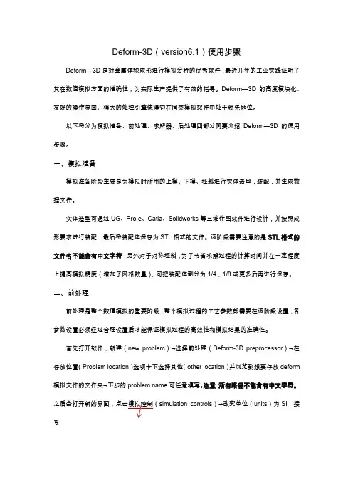
Deform-3D(version6.1)使用步骤Deform—3D是对金属体积成形进行模拟分析的优秀软件,最近几年的工业实践证明了其在数值模拟方面的准确性,为实际生产提供了有效的指导。
Deform—3D的高度模块化、友好的操作界面、强大的处理引擎使得它在同类模拟软件中处于领先地位。
以下将分为模拟准备、前处理、求解器、后处理四部分简要介绍Deform—3D的使用步骤。
一、模拟准备模拟准备阶段主要是为模拟时所用的上模、下模、坯料进行实体造型,装配,并生成数据文件。
实体造型可通过UG、Pro-e、Catia、Solidworks等三维作图软件进行设计,并按照成形要求进行装配,最后将装配体保存为STL格式的文件。
该阶段需要注意的是STL格式的文件名不能含有中文字符;另外对于对称坯料,为了节省求解过程的计算时间并在一定程度上提高模拟精度(增加了网格数量),可把装配体剖分为1/4,1/8或更多后再进行保存。
二、前处理前处理是整个数值模拟的重要阶段,整个模拟过程的工艺参数都需要在该阶段设置,各参数设置必须经过合理设置后才能保证模拟过程的高效性和模拟结果的准确性。
首先打开软件,新建(new problem)→选择前处理(Deform-3D preprocessor)→在存放位置(Problem location)选项卡下选择其他(other location)并浏览到想要存放deform 模拟文件的文件夹→下步的problem name可任意填写。
注意:所有路径不能含有中文字符。
simulation controls)→改变单位(units)为SI,接受弹出窗口默认值;选中模式(mode)选项卡下热传导(heat transfer)。
导入坯料、模具并设置参数:导入毛坯:1、general:通常采用刚塑性模型即毛坯定义为塑性(plastic),之后导入的模具定义为刚性(rigid);温度(temperature):根据成形要求设定坯料预热温度(温热成形时一定注意);材料(material):点击load选择毛坯材料,若材料库中没有对应的材料可选择牌号相近的。

操作教程一、进入Deform-3D界面进入运行Deform-3D v6.1程序,软件打开软件会自动选择安装时的默认目录,为了防止运算结果混乱不便管理,可单击工具栏中的打开按钮选择新的文件存放路径,如图10:单击此按钮,选择新的文件路径图10 选择新文件路径二、操作步骤1、进入前处理操作在主窗口右侧界面Pre Processor中Machining[Cutting]选项,弹出图11所示对话框,输入问题名称,单击【Next】按钮,进入前处理界面。
2、选择系统单位进入前处理界面会自动弹出图12所示对话框,要求选择单位制(英制或国际单位制),按需求选择国际单位制(System International),然后单击【Next】按钮,进入下一步。
3、选择切削加工类型Deform中给我们提供的加工方式有车削加工(Turing)、铣削加工(Milling)、钻削加工(Boring)、钻孔加工(Dtilling),其中我们模拟的是铣削加工,故选择Milling,然后单击【next】进入下一步,如图13所示。
图11 进入前处理操作1、选择国际单位制2、单击【Next】图12 选择系统单位制图13 选择切削加工类型4、设定切削参数图14所示对话框参数设置,可根据自己的需要改变数值的大小,不过后面选择刀具参数时要考虑这些参数,否则很肯能出现接触错误。
该模拟中选择参数如下:图14 设定切削参数5、工作环境和接触面属性设置1、选择铣削加工2、单击【Next 】2、单击【Next 】1、输入各项切削参数图15 工作环境和接触面属性设置5、刀具设置如图16所示,单击新建刀具在弹出的对话框中选择预先建立好的刀具模型(图17),单击打开按钮,弹出刀具材料设定对话框选择预先定义好的刀具材料物理参数的key 文件(图18),单击【load 】加载刀具材料。
所选刀具材料将被列在刀具材料设定对话框下方(图19)。
一直单击Next 直到完成刀具设置。
安装及破解详细说明1.解压文件: .rar到一文件夹,如下图所示:2.点击出现如下图所示画面:直接点击NEXT显示如下画面,不用管直接NEXT:继续,点击Yes:接下来选择安装目录如下图所示:,如果c 盘空间够大,装在里面就好了。
如果装在其它盘选择好安装目录后点击NEXT。
添加快捷方式下图所示:直接NEXT。
选择安装组件(两个钩都打上),直接NEXT。
按照License manager如下图所示:直接next。
选择License manager安装目录,(默认是C盘)直接NEXT对话框是说要求把一个PWD文件放在里面,不用管,确定就行,License manager安装画面如下:License manager安装完成,点击FINISHDeform开始安装,如下图所示:安装完Deform后还要安装MPICH如下图所示:,点击next同意协议,点击Yes选择MPICH安装目录(默认C盘即可),直接NEXT安装MPICH组件,直接NEXT.接下来也直接NEXTMPICH安装过程MPICH安装完成,点击Finish,(已经全部安装完成)提示是否重启电脑,随便你。
破解过程1.复制安装文件中MAGNiTUDE文件夹中的文件和文件到安装后的许可证文件夹DEFORM License Manager 文件夹中替换掉原来的两个文件,DEFORM License Manager 文件夹默认是在C:\Program Files\DEFORM License Manager 。
2.在上述文件夹里双击打开文件,不要关掉。
然后双击文件,选择on a remote server,点击,在弹出的选择框中选择自己的电脑,单击按钮check/Start Server,屏幕上会显示Connection is ok!(破解成功)不要关掉,打开程序——Deform—3D ——Deform3D既可使用:接下很关键:经此方法破解后,重启电脑后,Dform3D 可能都无法打开,解决方法如下:1.打开,方法如下:出现如下画面:选择on a remote server在IP name后面的白框中直接输入你的电脑名查看电脑名的方法如下:右键点我的电脑—选择属性,在弹出的属性对话框中选择计算机名:单击按钮check/Start Server,屏幕上会显示Connection is ok!按EXIT,退出后再依次打开C:\Program Files\DEFORM License Manager 。
Deform3D6、1安装及破解详细说明1、解压文件: DEFORM-3D、V6、1、SP1 、rar到一文件夹,如下图所示:2、点击SETUP、EXE出现如下图所示画面:直接点击NEXT显示如下画面,不用管直接NEXT:继续,点击Yes:接下来选择安装目录如下图所示:,如果c盘空间够大,装在里面就好了。
如果装在其它盘选择好安装目录后点击NEXT。
添加快捷方式下图所示:直接NEXT。
选择安装组件(两个钩都打上),直接NEXT。
按照License manager如下图所示:直接next。
选择License manager安装目录,(默认就是C盘)直接NEXT对话框就是说要求把一个PWD文件放在里面,不用管,确定就行,License manager安装画面如下:License manager安装完成,点击FINISHDeform开始安装,如下图所示:安装完Deform后还要安装MPICH如下图所示:,点击next同意协议,点击Yes选择MPICH安装目录(默认C盘即可),直接NEXT安装MPICH组件,直接NEXT、接下来也直接NEXTMPICH安装过程MPICH安装完成,点击Finish,(DEFORM6、1已经全部安装完成)提示就是否重启电脑,随便您。
破解过程1、复制安装文件中MAGNiTUDE文件夹中的deform、pwd文件与LManager、exe文件到安装后的许可证文件夹DEFORM License Manager 2、1文件夹中替换掉原来的两个文件,DEFORM License Manager 2、1文件夹默认就是在C:\Program Files\DEFORM License Manager 2、1。
2、在上述文件夹里双击打开LManager、exe文件,不要关掉。
然后双击DLConfig、exe文件,选择on a remote server,点击,在弹出的选择框中选择自己的电脑,单击按钮check/Start Server,屏幕上会显示Connection is ok!(破解成功)不要关掉LManager、exe,打开程序——Deform—3D V6、1——Deform3D既可使用:接下很关键:经此方法破解后,重启电脑后LManager、exe,Dform3D可能都无法打开,解决方法如下: 1.打开DLConfig、exe,方法如下:出现如下画面:选择on a remote server在IP addr、or name后面的白框中直接输入您的电脑名查瞧电脑名的方法如下:右键点我的电脑—选择属性,在弹出的属性对话框中选择计算机名:单击按钮check/Start Server,屏幕上会显示Connection is ok!按EXIT,退出后再依次打开C:\Program Files\DEFORM License Manager 2、1。
deform3Dv6.1热成形模拟步骤Hot Forming(热成形deform-3D模拟步骤)When simulating hot forming, it is important to simulate all steps of the process including transfer from the furnace, and resting on the die, since the temperature loss due to transfer from the furnace and from die chilling can influence flow behavior. The procedure for simulating a multi-station process is detailed at the end of this section.This section will outline the setup procedure for the following operations:1) Set uniform object temperature to simulate full furnace soak.2) Cool in air to simulate transfer from the furnace to the dies3) Rest on dies4) Forge5) Repeat for multiple forging blows1. Create a new problem folder (directory)Each DEFORM problem should reside in its own folder. However, a given problem may contain many operations, all in the same database file.2. Start the DEFORM preprocessor3. Set Basic Simulation ControlsThe simulation controls will be set for the first operation –simulating chilling during the transfer from the furnace to the press.a. Problem Title (optional)Descriptive title for the problem – will be displayed on the screen during pre- and post-processing.b. Operation NameOperation namec. Unit SystemSelect English or SI units. This will change many default values and affect how material data is imported.d. Select Simulation ModeFor simulating transfer of the workpiece from the furnace to the press, only heat transfer will be modeled, so turn on heat transfer, and turn off deformation.4. Define the MaterialDefine thermal properties for the material. For most steels, the files STEEL_E.KEY or STEEL_S.KEY contain reasonable thermal properties. These files can be loaded from the Material Properties menu on the main preprocessor window.5. Define the Workpiecea. Define Object TypeFor most simulations, plastic object type is suitable.b. Define the GeometryGeometry can be defined from an STL file.Workpiece geometry requirements: Geometry must be defined with normals facing outward Always check the geometry.c. Mesh the ObjectTypical progressions should use element sizes that represent thepart. When in doubt, more elements will tend to give more accurate results. Typical weights: Curvature=0.9 Strain Rate=0.7 Strain =0.5 Temp=0d. Define Thermal Boundary ConditionsFor solid parts, define heat exchange with the environment on all faces except the symmetry surfaces.e. Initialize Object TemperatureSet the initial object temperature to the furnace soak or preheat temperature.6. Complete Simulation Controlsa. Define Number of StepsA typical transfer operation can be simulated in 10 to 20 steps.b. Select the Primary DieEnter object 1 (only object defined) as the primary die.c. Calculate the Time per StepDivide the total transfer time by the number of steps.7. Save the DataSave a Keyword file.Go to Database Generation. Check the data. If there are any yellow or red flags, resolve them, then generate the database. Exit the preprocessor and start the simulation.8. Loading Simulation Results Into the Preprocessor to DefineSecond OperationReturn to the preprocessor, and load the last step from the database.9. Define Material Data for the toolsSpecify thermal data for the tool material10. Define the Toolsa. Assign Tool Names (optional)For reference during pre- and post-processing.b. Define Tool GeometryImport or define geometry for the upper die (punch) and lower die. The geometry rules detailed above for the workpiece all apply. Furthermore: For multi-piece tools, draw a single tool boundary defining all inserts,knockouts, etc. The geometry can be separated later for die stress analysis.Refer to the manual orcontact tech support if there is more than one moving tool for a given station. Extend the tool geometry slightly across the centerline. For tools with a sliding clearance between the punch and die, increase the OD of the punch to slightly intersect the die. Refer to the manual or training material for more details Put a slight flat on the tip of any pointed punches. While it is not strictly necessary, it is convenient to make object 2 the punch or moving object.c. Mesh the ToolsUse around 400 elements. Use user defined density with 3 at the contact surface and 1 on the back side of the die.d. Assign Tool MaterialBe sure the proper material is assigned to both the tools and the workpiecee. Assign Tool TemperatureSet the uniform tool temperature before forming begins.11. Define Interobject Dataa. Inter-Object RelationshipsThe workpiece should be slave to both tools. The interface heat transfer coefficient should be about 0.004 for English units, or 10 for SI units. b. Object PositioningUsing interference positioning, position the workpiece on the bottom die. Leave the top die away from the workpiece during this operation.c. Generate Contact Boundary ConditionsThe default value of tolerance is adequate.12. Complete Simulation Controlsa. Define Number of StepsA typical die resting operation can be simulated in 10 to 20 steps.b. Select the Primary DieEnter object 1 as the primary die.c. Calculate the Time per StepDivide the total transfer time by the number of steps.d. Define Operation Name (optional)13. Save the DataSave a Keyword file.Go to Database Generation. Check the data. If there are any yellow or red flags, resolve them, then generate the database. Exit the preprocessor and start the simulation.14. Loading Simulation Results Into the Preprocessor to Define Forming OperationReturn to the preprocessor, and load the last step from the database.15. Set Simulation Controlsa. Operation Name (optional)b. Select Simulation ModeWe will now simulate the forging operation, so turn deformation on (yes) 16. Define Material Data for Workpiece Assign plastic (flow) data for the workpiece material. Be sure the material selected covers the proper temperature range, including any deformation heating and die chilling.17. Assign Top Die (punch) MovementPress behavior may play a role in results. Consult the manual or SFTC tech support for more information on press behavior.Set the direction (typically downward). The stroke value should not be changed unless a mechanical press model is used.18. Define Interobject Dataa. Inter-Object RelationshipsAssign a friction factors. For lubricated hot forging, values of0.2 to 0.3 are typical. For non-lubricated hot forging, values of 0.8 to 1.0 are typical.b. Object PositioningUsing interference, with the workpiece as the reference object, position both tools in contact with the workpiece.c. Generate Contact Boundary ConditionsThe default value of tolerance is generally adequate19. Complete Simulation Controlsa. Define the Number of Steps For very limited deformation, such as a square-up or buster, use 50 steps For average deformation, such as heading, use 100 steps For problems with a large amount of deformation, such as extrusion, 200 or more steps are appropriate.b. Assign the Primary DieThe top die (or punch) should be the primary die. This will generally be object #2.c. Calculate the Stroke per StepEstimate the distance the top die will move (from the point it contacts theworkpiece) Divide this value by the number of steps, and enter this value in Stroke per Step. If you are unsure of total punch stroke, add 10 or 15 extra steps.This will overshoot the goal, and you can back up a few steps to get the ending shaped. Set Stopping Controls (optional)If you know the exact distance the punch will move, enter this value under stopping controls. If no value was entered, the simulation will stop when all steps have been completed.e. Set substepping controlUnder Advanced Step Controls, set Strain per Step to 0.02520. Save the DataSave a keyword file.Go to Database generation, Check the data. If there are any yellow or red flags, resolve them, then generate the database. Exit the preprocessor and start the simulation.21. Running a Second Operationa. Identifying the endpoint of the first operationAfter the simulation is completed, go to the Post-Processor, and check the results. Identify the step at which the first operation will be completed, and make a note of this step number.b. Loading Simulation Results Into the Preprocessor.Return to the preprocessor, and load the appropriate step from the database.c. Simulate Chilling During Transfer to Next StationConsider the transfer time between stations. Refer to the beginning of this section for guidelines on running heat transfer simulations.d. Changing T ool GeometryGo to the Geometry editor, delete the tool geometry (not the whole object), and import or create new tool geometry for each tool.e. Positioning ObjectsFrom Interobject reposition the tools against the workpiece usinginterference.f. Generate ContactInitialize and generate contact boundary conditions.g. Reset Simulation ControlsDetermine total steps and stroke per step as described above.h. Reset Stopping StrokeIf the stroke stopping control was used, reset the stroke to zero on object movement controls, and reset the stopping control under simulation controls.i. Write The DatabaseWriting an old database will append data to the end of the existing database. It will overwrite any steps after the step that was loaded.j. If the appropriate ending step is not saved…..If you encounter a situation where, say, step 90 is not formed enough, step 100 is formed too much, and there are no steps saved in between, you can load step 90, change the save interval to 1 (save every step), then rerun the last 10 steps of the simulation to get the proper stopping step.。
Deform3D6.1安装及破解详细说明1.解压文件: DEFORM-3D.V6.1.SP1 .rar到一文件夹,如下图所示:2.点击SETUP.EXE出现如下图所示画面:直接点击NEXT显示如下画面,不用管直接NEXT:继续,点击Yes:接下来选择安装目录如下图所示:,如果c盘空间够大,装在里面就好了。
如果装在其它盘选择好安装目录后点击NEXT。
添加快捷方式下图所示:直接NEXT。
选择安装组件(两个钩都打上),直接NEXT。
按照License manager如下图所示:直接next。
选择License manager安装目录,(默认是C盘)直接NEXT对话框是说要求把一个PWD文件放在里面,不用管,确定就行,License manager安装画面如下:License manager安装完成,点击FINISHDeform开始安装,如下图所示:安装完Deform后还要安装MPICH如下图所示:,点击next同意协议,点击Yes选择MPICH安装目录(默认C盘即可),直接NEXT安装MPICH组件,直接NEXT.接下来也直接NEXTMPICH安装过程MPICH安装完成,点击Finish,(DEFORM6.1已经全部安装完成)提示是否重启电脑,随便你。
破解过程1.复制安装文件中MAGNiTUDE文件夹中的deform.pwd文件和LManager.exe文件到安装后的许可证文件夹DEFORM License Manager 2.1文件夹中替换掉原来的两个文件,DEFORM License Manager 2.1文件夹默认是在C:\Program Files\DEFORM License Manager 2.1。
2.在上述文件夹里双击打开LManager.exe文件,不要关掉。
然后双击DLConfig.exe文件,选择on a remote server,点击,在弹出的选择框中选择自己的电脑,单击按钮check/Start Server,屏幕上会显示Connection is ok!(破解成功)不要关掉LManager.exe,打开程序——Deform—3D V6.1——Deform3D既可使用:接下很关键:经此方法破解后,重启电脑后LManager.exe,Dform3D可能都无法打开,解决方法如下:1.打开 DLConfig.exe,方法如下:出现如下画面:选择on a remote server在IP addr.or name后面的白框中直接输入你的电脑名查看电脑名的方法如下:右键点我的电脑—选择属性,在弹出的属性对话框中选择计算机名:单击按钮check/Start Server,屏幕上会显示Connection is ok!按EXIT,退出后再依次打开C:\Program Files\DEFORM License Manager 2.1。