思普云设备组态管道使用说明操作教程
- 格式:pdf
- 大小:2.43 MB
- 文档页数:12
本章内容新建设备定义基本变量定义数据模型变量概述本章主要讲解如何定义设备,如何定义变量。
本培训工程中用到的变量主要为基本变量与模型变量。
KingSCADA的采集系统是指负责和现场设备进行通讯,并采集现场数据和控制现场数据的模块,称之为采集器,也叫KingIOServer应用,它是一组独立的应用程序,依赖于驱动产品,通过驱动与IO设备进行通讯。
采集系统由通讯链路,设备,数据块组成。
链路:链路是指计算机通过什么途径和设备进行连接,链路类别:串口,以太网,GPRS,Modem,通信卡,采集卡,无链路。
设备:设备是通过串口、接口板等方式与KingSCADA的数据采集系统进行数据信息交换的外部数字设备,包括可编程逻辑控制器(PLC)、分布式控制系统(DCS)、回路控制器、远程终端单元(RTU)、智能仪表、板卡、变频器等等。
变量:变量是对应硬件设备具体通道或地址的标识,由设备监视和控制的,反映现场运行状况的参数信息,如:温度、压力、流量等,在其他系统有时被称为I/O变量。
第一节建立硬件系统新建设备第一步:在Windows桌面上点击“开始”→“所有程序”→“KingIOServer3.7”→“KingIOServer 工程设计器”选项,弹出工程设计器界面,该界面与Windows的资源管理器很相似,操作方式也基本相同。
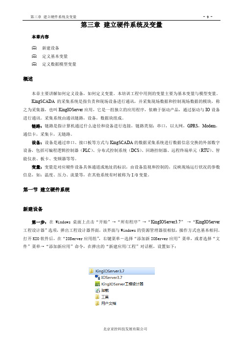
打开KIO软件后,在“IOServer应用组”,右键菜单-选择“添加新IOServer应用”菜单,或者选择“文件”菜单→“添加新应用”命令,在弹出的“新建应用/工程”对话框,设置如下:图3-1打开IOServer和新建I/OServer应用对话框一个工程中可以建立多个IOServer应用,且IOServer应用可以脱离KingSCADA独立存在。
IOServer 应用分本地IOServer应用(KingSCADA与IOServer应用在同一台机器上)和远程IOServer应用(KingSCADA与IOServer应用不在同一台机器上),区别在于IOServer应用中的网络配置。

陕甘宁盐环定扬水管理处综合自动化组态软件系统运行操作说明大唐软件技术股份目录一、系统功能概述 (3)1.1数据采集与处理 (3)1.2报警功能 (3)1.3曲线及报表 (4)1.4遥控 (4)二、计算机系统的上电和PECSTAR软件系统的启动 (4)三、计算机监控软件的操作 (5)3.1前台通信管理程序使用简介 (5)3.1.1在线投退通信子站 (7)3.1.2在线投退设备 (7)3.1.3手动清除电度 (7)3.1.4修改数据显示有效位数 (8)3.1.5手动修改测量值 (8)3.2图形查询 (9)3.2.1登录/注销操作 (9)3.2.2图形操作 (10)3.2.3事件报警操作 (12)3.2.4窗口布置 (13)3.2.5系统属性设置 (13)3.2.6一般属性 (13)3.2.7执行其它程序 (16)3.2.8退出系统 (16)3.3报表制作和查询 (16)3.3.1主要功能 (16)3.3.2主要容 (17)3.3.3后台程序运行条件 (17)3.3.4报表设计工具启动 (17)3.3.5表格查询类型权限设置 (18)3.3.6绘制编辑表格 (19)3.3.7报表保存 (20)3.3.8报表查询 (21)3.4系统备份及恢复 (21)3.4.1数据备份 (21)3.4.2软件系统的恢复 (22)一、系统功能概述1.1数据采集与处理⑴实时采集模拟量、开关量、对实时数据进行统计、分析及计算。
⑵实时显示各回路的电流、电压。
⑶实时显示高压各回路的功率因数。
⑷实时显示各回路的有功功率值。
⑸实时显示各高压进线的频率。
⑹实时显示、统计各回路各时段的电度值;⑺实时显示、统计各回路每日、每月的有功电度总值和无功电度总值1.2报警功能⑴设置预告信号和事故信号,产生不同的音响报警,窗口提示事件容。
⑵预告信号部分:线路过负荷、系统自诊断故障、母线电压越限、电流越限等。
⑶事故信号部分:保护装置的保护动作。
1.3曲线及报表⑴电流棒图、电压棒图、负荷棒图等实时刷新显示图。

AdvanTrol-Pro V2.70系统组态使用手册浙江中控技术股份有限公司声明⏹严禁转载本手册的部分或全部内容。
⏹在不经预告和联系的情况下,本手册的内容有可能发生变更,请谅解。
⏹本手册所记载的内容,不排除有误记或遗漏的可能性。
如对本手册内容有疑问,请与我公司联系。
文档标志符定义警告:标示有可能导致人身伤亡或设备损坏的信息。
WARNING: Indicates information that a potentially hazardous situation which, if not avoided, could result in serious injury or death.电击危险:标示有可能产生电击危险的信息。
Risk of electrical shock: Indicates information that Potential shock hazard where HAZARDOUS LIVE voltages greater than 30V RMS, 42.4V peak, or 60V DC may be accessible.防止静电:标示防止静电损坏设备的信息。
ESD HAZARD: Indicates information that Danger of an electro-static discharge to which equipment may be sensitive. Observe precautions for handling electrostatic sensitive devices注意:提醒需要特别注意的信息。
ATTENTION: Identifies information that requires special consideration.提示:标记对用户的建议或提示。
TIP:Identifies advice or hints for the user.目录系统组态 (1)1 概述 (1)2 系统组态步骤 (1)3 组态界面介绍 (2)3.1 组态界面启动 (2)3.2 组态界面整体介绍 (2)3.3 组态树的基本操作 (3)3.4 菜单命令 (4)4 系统总体组态操作说明 (6)4.1 主机设置 (6)4.2 全体编译 (11)4.3 备份数据 (14)4.4 组态下载 (15)4.5 组态发布 (17)4.6 控制站信息 (21)4.7 报警限上载 (21)4.8 配置DP组态、DP组态下载、查看控制位号 (23)4.9 组态调试 (24)4.10 下载记录查看 (25)4.11 系统组态结果信息打印 (25)5 系统总体设置 (26)5.1 报警文件设置 (26)5.2 趋势文件设置 (27)5.3 操作记录设置 (28)5.4 报警颜色设置 (28)5.5 用户设置 (30)5.6 区域设置 (31)5.6.1 概述 (31)5.6.2 操作步骤 (31)5.7 策略设置 (34)5.7.1 概述 (34)5.7.2 网络策略的设置 (35)5.7.3 单张策略详细设置 (36)6 控制站组态操作界面说明 (37)6.1 数据转发卡组态 (37)16.3 I/O点组态 (39)6.4 模拟量输入信号点参数设置 (40)6.5 脉冲量输入信号点参数设置 (43)6.6 PAT信号点参数设置 (44)6.7 模拟量输出信号点设置 (45)6.8 开关量输入/输出信号点参数设置(及SOE输入设置) (45)6.9 电量输入信号点参数设置 (46)6.10 I/O点趋势组态 (46)6.11 I/O点报警组态 (47)6.12 I/O点分组分区设置 (51)6.13 I/O点语音报警设置 (51)6.14 自定义1字节变量组态 (52)6.15 自定义2字节变量组态 (54)6.16 自定义4字节变量组态 (55)6.17 自定义8字节变量组态 (56)6.18 自定义回路组态 (57)6.19 常规控制方案组态 (58)6.20 自定义控制方案组态 (60)6.21 折线表定义 (61)6.22 SOE编辑 (64)6.23 位号区域划分 (65)6.24 位号统计信息 (68)7 操作站组态操作界面说明 (68)7.1 操作小组设置 (68)7.2 总貌画面组态 (69)7.3 趋势画面组态 (72)7.4 分组画面组态 (75)7.5 一览画面组态 (76)7.6 流程图组态 (76)7.7 光字牌组态 (79)7.8 报表组态 (82)7.9 自定义键组态 (83)7.10 弹出式流程图组态 (86)7.11 二次计算组态 (86)7.12 语音报警组态 (88)7.13 画面跳转组态 (102)27.15 Web发布 (106)8 资料版本说明 (106)3系统组态1概述系统组态是指对集散控制系统(Distributed Control System—DCS)的软、硬件构成进行配置。

组态软件操作指南概述本章内容KingSCADA软件结构KingSCADA软硬件环境KingSCADA与外部设备KingSCADA软件结构KingSCADA是一种通用的工业监控软件,它融过程控制设计、现场操作以及工厂资源管理于一体,将一个企业内部的各种生产系统和应用以及信息交流汇集在一起,实现最优化管理。
它基于Windows XP/Windows 7/Windows 8/Windows10/Windows Server 2008/Windows Server 2012等操作系统,并支持多语言的操作系统。
用户可以在企业网络的所有层次的各个位置上及时获得系统的实时信息与历史信息。
采用KingSCADA开发工业监控系统,可以极大地增强用户生产控制能力、提高工厂的生产力和效率、提高产品的质量、减少成本及原材料的消耗。
它适用于从单一设备的生产运营管理和故障诊断,到网络结构分布式大型集中监控管理系统的开发。
KingSCADA软件结构由工程设计器、画面编辑器及运行系统三部分构成。
工程设计器:工程设计器是一个应用开发设计工具,用于创建应用、创建监控画面、定义监控的设备、定义相关变量、命令语言以及设定运行系统配置等系统组态工具。
画面编辑器:在画面编辑器中用户可以绘制图形画面、设置动画链接、配置报警窗口、配置趋势曲线窗口等与图形有关的所有操作。
运行系统:工程运行界面,从采集设备中获得通讯数据,并依据画面编辑器的动画设计显示动态画面,实现人与控制设备的交互操作。
KingSCADA软硬件环境1、硬件要求硬件:Intel 酷睿2 双核4线程内存:2G硬盘空间:KingSCADA完全安装占用空间需约350M,建议100GB硬盘。
显示器:VGA、SVGA或支持桌面操作系统的任何图形适配器。
要求最少显示256色,推荐无限色支持鼠标:任何PC兼容鼠标通讯:RS-232CUSB接口:用于插入KingSCADA加密锁(软授权不用)(KingSCADA对于主频有一定要求,对于有较多逻辑脚本系统,建议2.3GHz以上)2、软件要求KingSCADA与外部设备Windows操作系统,支持的操作系统语言版本:中文简体、英文、日文Windows 7专业版和旗舰版Window 8专业版和旗舰版Window 10专业版和旗舰版Windows Server 2012专业版和旗舰版Windows Server 2008专业版和旗舰版Windows Server 2003 专业版和旗舰版Windows Xp sp3Windows Vista专业版和旗舰版注:支持32位和64位,不支持Home版。

云100s使用手册一、产品简介云100s是一款高效、智能的云端存储设备,提供安全可靠的数据存储、备份和共享服务。
具有大容量、高速传输、易于管理等优点,适用于个人、家庭及企业用户。
二、设备安装1.将云100s连接至计算机或路由器,确保电源充足。
2.下载并安装云100s客户端软件,根据提示完成设备初始化设置。
3.登录账号,按照界面指引设置密码及安全问题,完成设备注册。
4.等待设备自动升级完毕后,即可开始使用。
三、账号注册与登录1.打开云100s客户端,点击“注册新账号”按钮,填写相关信息完成注册。
2.登录账号:打开云100s客户端,输入账号及密码,点击“登录”按钮。
3.退出账号:在客户端界面点击“退出”按钮,即可安全退出账号。
四、基本操作界面1.文件管理:可以浏览、上传、下载存储在云100s中的文件。
2.文件夹管理:可以新建、删除、重命名文件夹,对文件夹进行分类管理。
3.分享功能:可以将文件或文件夹分享给其他人,支持链接加密、访问权限设置等功能。
4.搜索功能:支持关键词搜索,快速找到所需文件。
5.回收站:删除的文件将移至回收站,可选择恢复或彻底删除。
五、主要功能介绍1.数据备份:支持自动备份手机、电脑等设备中的重要数据,确保数据安全。
2.家庭共享:支持多人共享同一云空间,方便家庭成员之间共享照片、视频等资料。
3.多平台支持:支持PC、手机、平板等多种终端设备,随时随地访问云端数据。
4.下载速度限制:支持下载文件速度限制功能,便于管理存储空间及流量使用情况。
5.文件版本管理:支持文件版本管理功能,可回溯文件历史版本。
6.自动捕获剪贴板内容:支持自动捕获剪贴板内容功能,方便用户快速上传文件至云端。
7.下载任务管理:支持下载任务管理功能,可查看下载内容及进度,方便用户管理下载文件。
8.在线编辑:支持在线编辑功能,可直接在云端对文档进行编辑和保存。
9.数据加密:采用先进的加密技术,确保用户数据安全可靠。
同时支持外链加密分享,防止数据被窃取或非法访问。
SI-EPG系统用户使用手册V4.0北京算通科技发展股份有限公司2010-1关于本手册本手册详细描述了算通SI-EPG安装、设置和操作方法。
请仔细阅读本手册,以确保正确操作您的SI-EPG。
注意:请使用质量较好的线缆,确认接头良好;请确认您使用的电源符合要求,不要使用没有地线的电源线;请不要轻易打开机盖。
目录前 言 (3)第一章 概述 (4)1.1产品简介 (4)1.2产品附加配件 (4)第二章 产品说明 (5)2.1基本原理 (5)2.2主要功能 (5)2.3系统的软件组成 (6)2.4系统配置要求 (6)第三章 操作指南 (8)3.1预处理 (8)3.2操作流程 (8)3.3SI-EDITOR(SI编辑器) (9)3.3.1操作界面 (9)3.3.2 SI服务信息配置 (17)3.4SI-GENERATOR配置操作 (43)3.5EPG-EDITOR事件编辑器 (45)3.5.1操作界面 (45)3.5.2 数据库管理操作 (53)3.5.3 节目单编辑操作 (56)3.6SI-SEND播出监控器 (61)3.6.1 操作界面 (61)3.6.2 SI-SEND软件操作 (66)第四章 注意事项 (78)第五章 技术指标 (79)5.1技术参数 (79)5.2参考标准 (79)前 言北京算通科技发展股份有限公司是中国领先的数字电视前端软件、硬件产品及系统解决方案提供商。
公司成立于1997年,创始团队成员来源于中国科学院计算所、哈尔滨工业大学、清华大学等知名院所以及MPEG组织中国代表团等行业标准组织,从1996年就开始参与MPEG相关标准的制定工作,在数字电视领域积累了丰富的经验。
近几年,我们一直积极配合国家数字电视产业相关指导部门,积极参与中国数字电视标准的研讨和制定,包括信源编码(AVS),条件接收,交互电视中间件等主要核心技术标准。
公司按照国际标准建立了质量管理体系,并通过ISO9001:2000质量体系认证,增强了企业核心竞争力,为实现可持续发展奠定了坚实的基础。
组态知识应用操作指导书1硬件组态1.1 创建系统(创建工作平台)方法一:由双击快捷键,进入以下画面。
方法二:由开始/所有应用程序/Triconex/TriStation 1131 进入。
进入以下画面,按File/New Project按钮。
选择你要创建的系统,按OK按钮。
给出文件路径,起文件名,按保存按钮。
1.2项目命名原则:1.2.1 Tristation 1131项目名称文件的命名(project name)---如何建立工程项目文件名(T/C)--(N/T)----(XYZ)---(ABCD)T-----美元合同C-----人民币合同N-----tricon控制系统T------trident控制系统XYZ---表明由本公司工程部和售后服务部亲手做的项目,以主机架为单位。
ABCD---表明合同部每年管理的项目号,A为年,BCD为该年的项目号。
1.2.2 位号命名约定:I/O符号说明:w—未被标定的模拟量输入(DINT)a---定标模拟输入(REAL)v---未被标定的模拟量输出(DINT)y---定标模拟输出(REAL)d---数字量输入(BOOL)c---数字量输出(BOOL)t---温度输入(DINT)p---脉冲输入(REAL)1.2.3 内部信号符号说明:r---内部模拟量(REAL)i---内部模拟量(DINT)e---内部读写模拟量f---内部只读模拟量g---内部读写数字量(Read/Write)k---固定常数(Real/Bool)t---时间常数(TIME)m---报警信号(BOOL)n---连锁记忆位形成1131的数据库。
进入控制面板更换主处理器:双击现有的主处理器,弹出画面如下:按Replace MPs钮,弹出画面如下:选中3008,按OK。
出现画面如下:置换成功。
2.2 组态通讯卡2.2.1 将NCM4329卡件由C1移出,见下图,按Remove按钮。
如:安装在C1S7,则选中此槽位。
SuperCloud OperationManual(Version:V1.7.1)Hunan Huacheng Zhitong Technology Co., Ltd.November 2019catalogue1.Introduction (1)1.1.Purpose of writing (1)1.2.Background of the project (1)1.2.1.Development of Industrial Internet of Things (1)1.2.2.Development needs of the Industrial Internet of Things (2)1.2.3.Significance of the Industrial Internet of Things (2)1.3.References (3)2.SuperCloud Console operation guide (3)2.1.SuperCloud Address (3)2.2.Log in (3)2.3.System Overview (4)2.4.Product Equipment (6)2.4.1.Product Management (7)2.4.2.Device Management (12)2.5.Gateway Management (15)2.5.1.Gateway Configuration (15)2.6.Configuration Management (18)2.6.1.Standby configuration (18)2.6.2.Production line configuration (24)2.7.Video Management (25)2.8.Fault Management (28)2.8.1.Parameter settings (28)2.9.Maintenance Project (29)2.10.Gang Control (31)2.10.1.Linkage Rule (31)2.10.2.Add rules (31)2.10.3.Control Log (32)2.11.Message notification (32)2.11.1.Message notification setting (32)2.11.2.Message sending record (35)2.12.SMS management (36)2.12.1.Purchase of recharge (36)2.13.Space management (37)2.14.Internet of things card management (38)2.15.Knowledge Classification (39)2.16.System Management (40)er Management (41)2.16.2.Role Management (43)2.16.3.Operation log (45)2.16.4.System Setup (45)3.SuperCloud Big Data Center Operations Guide (46)3.1.GIS map (47)3.2.Real time protection (48)3.2.1.Real-time data (48)3.2.2.Real-time configuration (50)3.2.3.Real-time video (50)3.3.Maintenance Center (51)3.3.1.Historical fault (51)3.3.2.Maintenance notice (52)3.3.3.Work Order Management (53)3.4.Historical Data (62)3.4.1.Data display (62)3.4.2. DA (63)3.5.KBM (65)3.6.Telecontrol (67)3.7.Remote programming (70)4.SuperCloud APP (71)4.1.Download APP (71)4.2.Login APP (74)4.3.APP function module (74)4.3.1.Equipment (74)4.3.2.Production line (83)4.3.3.Maintenance and protection (84)4.3.4.News (86)4.3.5.Mine (87)SuperCloud Operation Manual1.IntroductionSuperCloud Platform is a management cloud platform developed by Hunan Huachen Zhitong Technology Co., Ltd.SP Industrial Cloud Platform focuses on effectiveness,Feature-rich,Simple and efficient operation,Beautiful and elegant interface.Each functional module is clear,Support user-defined permission management and page configuration,User operation is more efficient, convenient and flexible.Monitor equipment and data in real time0,Provides parametric graphs and live video,Send equipment fault alarms in real time.1.1.Purpose of writingThis operation manual is for reference of the operator of SuperCloud,Explain to users how to operate the SuperCloud Platform.1.2.Background of the project1.2.1. Development of Industrial Internet of ThingsIndustrial IoT promotes industrial transformation and upgrading.With the rapid development of the Internet of Things technology, a series of national strategies such as Made in China 2025, the US Advanced Manufacturing Partnership Program, and German Industry 4.0 have been proposed and implemented. Under this background, the Industrial Internet of Things has emerged as the times require, and it has become an intelligent change in the global industrial system Important promoter. The Industrial Internet of Things is mainly used in all aspects of the entire life cycle of design, production, management, and service. It is an important part of China's strategic emerging industries and contains great economic value. The transformation of traditional industries with the Industrial Internet of Things will definitely increase the economicSuperCloud Operation Manual added value of the industry, vigorously promote the transformation of China's economic development mode from production-driven to innovation-driven, and promote the adjustment of China's industrial structure.1.2.2. Development needs of the Industrial Internet ofThingsThe Industrial Internet of Things fits the needs of industrial applications. At present, the industrial Internet of Things in China is led by the government to shift to application needs. Enterprises have begun to apply the Industrial Internet of Things to solve practical problems they face, such as real-time monitoring of the status of production equipment, raw materials, work in progress, and staff through sensor instruments to achieve manufacturing. The process can only be executed to improve production efficiency and product quality; build intelligent storage through RFID and other identification technologies, and connect with the production process to improve the efficient configuration of manufacturing raw materials; internal equipment products obtain data through sensing means to achieve predictive early warning , Remote maintenance and other services; improve the added value of equipment products. The in-depth application of the Industrial Internet of Things in all aspects of the industrial manufacturing field will help improve many dilemmas such as overcapacity and increased cost pressure.1.2.3. Significance of the Industrial Internet of ThingsThe Industrial Internet of Things helps smart manufacturing. China's manufacturing industry is facing the strategic tasks of improving production efficiency, realizing energy saving and emission reduction, and completing industrial structure adjustment. The Industrial Internet of Things will bring profound changes to the production, operation and management modes of enterprises. Intelligent manufacturing is based on the deep integration of new-generation information and communication technology and advanced manufacturing technology. It runs through all links of manufacturing activities such as design, production, management, and service. New production methods and the deployment of the Industrial Internet of Things provide theSuperCloud Operation Manual cornerstone for intelligent manufacturing. Intelligent manufacturing will combine the Industrial Internet of Things, reasonably deploy the supply chain voluntarily to improve production and service efficiency, and realize the intelligent management model innovation of the manufacturing industry.1.3.References《Industrial Internet of Things White Paper》2.SuperCloud Console operation g uide 2.1.SuperCloud Address/idosp/login.html2.2.Log inOpen browser(Firefox / Google Chrome recommended),After entering the address, press the Enter key to enter the SuperCloud platform login page. Enter the user name and password and click Login.(1)Remember passwordCheck [Remember Password], you don't need to re-enter your password when you log in next time.SuperCloud Operation Manual (2)forget passwordClick [Forgot Password], enter username, mobile phone number, verification code, new password. Click OK.2.3.System OverviewAfter logging in successfully, you will enter the SuperCloud homepage system overview interface. Use the ring diagram to count the SMS usage, SIM card traffic alarm, storage space, gateway information, and device information. Use the progress bar to count the total number of users and the number of users online. Status, video.(1)Enter the SuperCloud Big Data CenterSuperCloud Operation ManualClick the icon in the upper right corner of the interface ,Jump to SuperCloud Big Data Center.(2)Download documentationClick on the icon in the upper right corner of the interface ,Select the document you want to download.(3)Change of passwordClick modify password on the menu bar,Enter the original password and the new password click OK.(4)log downClick on the menu bar [exit system], pop-up prompt, click OK, exit login.2.4.Product EquipmentProduct Management and Device Management are included under the productequipment.Steps:new product > new build point table > new build ready > binding gateway > force sync point table.2.4.1. Product ManagementProduct management includes the retrieval, addition, modification, deletion, andpoint-of-point configuration of the product.Step:Add Products>Point Table Configuration.The icon indicates that the product is bound to the device, the dot table cannot be imported in batches, can be modified individually, and the modified historical data will be emptied.The icon indicates that the product is not bound to the device and can be imported inbulk.(1)Search for ProductsEnter the product name and the system automatically retrieve the product information.(2)Add a ProductClick [add], fill in the product information, red box is required;(3)Modify ProductSelect the product that needs to be modified click [modify], click [OK] after the change.SuperCloud Operation Manual(4)Delete ProductSelect the product you want to delete, click delete, click OK.(5)Point Table ConfigurationAddClick[Point Table Configuration] to enter the point table configuration interface, andclick Add to fill in the variable information.ReviseSelect a variable to click Modify, and then click OK.、SuperCloud Operation Manual●DeleteSelect variable click [delete].●Import/ ExportClick [Export] to export Excel to the local file.Click [import], select point table profile from local file click submit.Interlock VariableClick[variable interlock], and select the variable to click Save.2.4.2. Device ManagementDevice management has six functional points: retrieval, addition, modification, deletion, binding gateway, forced synchronization point table.Step: Add Device> Bindings Gateway> Force Synchronization Point Table.Enter the device name and the system automatically retrieves the device information.(2)New EquipmentClick Add to fill in the device information, select the product, and click [OK].(3)Modification of equipmentSelect the device that needs to be modified and click [modify], click [OK] aftermodification.Select the device that needs to be deleted, click Delete, and click [OK].(5)Binding gatewaySelect the device to click the[Binding Gateway], check the gateway, select the channel number, and fill in the IP address, physical port, port number, rack number and slot number of the PLC.(6)Forced synchronization point tableAfter modifying the collection cycle, you need to click on the forced synchronization point table.2.5.Gateway Management2.5.1. Gateway ConfigurationThe gateway configuration interface consists of four functional points: retrieval, modification, remote management of gateway parameters, maintenance application and maintenance record.(1)Retrieval gatewayEnter the Gateway ID and the system automatically retrieves the gateway-related information.(2)Modify gatewaySelect the gateway click [modify], modify and click [OK].(3)Remote management of gateway parametersGet gateway parametersSelect the gateway click [gateway parameter remote management], click "read" to automatically get the gateway parameters.●LAN port parameter settingThe function code selects the LAN port parameter setting, clicks [reads], reads the LAN port parameter.●Force the gateway to restartFunction code selection forced restart gateway, click [write].(4)Application for maintenance of maintenanceSelect the gateway to click on the maintenance application, fill in the description information and click OK.SuperCloud Operation Manual (5)Maintenance recordSelect the gateway to click on the maintenance record, select to view the maintenance type, view the maintenance record.2.6.Configuration Management2.6.1. Standby configurationThe device configuration interface contains 8 function points, retrieves, creates, deletes, modifies, copy, view, untie, and configures the configuration interface.Step: Create a new template and then design the configuration.(1)RetrievalSuperCloud Operation Manual Enter the template name and the system automatically retrieve the templateinformation.(2)New TemplateClick New template, enter the template name, and click OK to bind the product.(3)Delete TemplateSelect the template click [delete], pop-up prompt and click OK. Multiple templates can be selected for bulk deletion.(4)Modify the templateSelect the template to click Modify, and then click OK.(5)Copy TemplateSelect template click [copy], click ok.(6)View TemplateSelect the template and click View.(7)Untie productSelect the template click [untie], pop-up prompt click OK.(8)configuration designSelect the template to click Configuration Design to enter the configuration designinterface, PC configuration, click on the "PC (configuration)" configuration design,APP configuration, click the configuration design under the "Configuration (APP)". (9)Interface analysis of configuration designThe configuration design interface is divided into a menu bar, a left column, and a rightcolumn.Menu bar and function points: file, edit, view.●[file]: set resolution, save, background color.●[Edit]: Find objects, label replacement, text replacement, upload picture,graphic control, user drawing, undo, redo, copy, paste, cut, delete, clear,select all, and deselect.●[View]: Pan, Grid, set up the network, align to the grid, display the leftcolumn, display the right column, the label browser, the Statistics Use tab,and the display layer.The left column menu includes general, drawing, configuration, sewage treatment (static), ruler, chart, interaction, connection, arrow, shared control, user picture.Currently available controls:●the conventional text;● a straight line, a rectangle, a circle, a rounded rectangle, an ellipse andan arc under the drawing;●the label value, the circular indicator light, the rectangular indicator lightand the progress bar under the configuration;●graphic control under[Edit]Control property settings:●Text sets the attribute in the right-hand column "L Label Text";●Lines, rectangles, circles, rounded rectangles, ellipses, arcs set propertiesunder "Shape" in the right column;●Label value, circular indicator, rectangular indicator, progress bar in the rightcolumn "E extension" set properties.(10)Configuration Design Steps●In the first step, the configuration is designed, and the required configuration controlis selected from the left column to form a complete configuration.●Step 2: Set the attribute, and set the configuration attribute and other information inthe right column according to the requirement.●Step 3, set the variable, select the control to click on the [Quick Settings] in the upperrightcorner of the web page,Click Icon ,After clicking on the label name, Icon ,Select a variable, click OK, and then click the button.●Step 4, click on the icon , Save the configuration file.Click on the icon to enterthe configuration preview interface .2.6.2. Production line configurationProduction line configuration interface includes 8 functions, retrieval, new template, delete, modify, view (APP), configuration design (PC), configuration design (APP).A configuration binds multiple devices.(1)Retrieval production lineEnter the name of the production line and automatically retrieve the production line information.(2)New TemplateFill in the line name, bind multiple devices, and click OK.SuperCloud Operation Manual(3)Delete a production lineSelect template click [delete], pop-up prompt click OK.(4)Modify LineSelect the template to click Modify to enter the modification line interface, and then click OK.)5)View (PC) Production LineClick View (PC) to view the PC end production line.(6)View the (APP) production lineClick View (APP), to view the AP side of the production line.(7)Configuration Design StepsConfiguration design is divided into 4 steps, design configuration, set properties, set variables, save and view real-time configuration.2.7.Video ManagementThe video management interface contains 6 functions: retrieving, adding, modifying, deleting, binding devices, and sorting.The video management list records the video number, video name, video link,binding device and notes.(1)Retrieval of videoEnter the video name, and the system automatically retrieves the video information.(2)New videoClick [add], enter the video name and video link click OK.(3)Modify the videoSelect the video to click Modify, and then click OK.(4)deletion of videoSelect video click [delete], pop-up prompt, click OK.(5)Video binding equipmentSelect the video click [bind device], check the device click OK. The video binds to the selected device, and the video can be viewed after the device is selected.(6)上移/下移视频Click,the video can be set,Click,Move the video up one bit,Click,Move the video down one bit.2.8.Fault ManagementSuperCloud Operation Manual 2.8.1. Parameter settingsThe parameter setting of fault management consists of two functional points, setting parameters and synchronization parameters.After selecting the product, set the fault parameters, and then click [synchronization parameters], the alarm parameters will be updated synchronously.(1)Parameter settingsClick , Enter the parameter setting interface, fill in the fault name, select the alarm mode, set the alarm parameter, and click OK.trigger mode: set a value that triggers an alert or alarm when the variable is the valueSuperCloud Operation Manual Limit mode: Set two values, one is the lowest value, one is the highest value, and the warning or alarm is triggered when the variable is the lowest value or thehighest value.2.9.Maintenance ProjectThe maintenance plan consists of four functions: retrieval, addition, modification and deletion.(1)RetrievalEnter the product name system to automatically retrieve the maintenance plan. (2)NewSelect maintenance plan, click add, set maintenance plan click OK.SuperCloud Operation Manual(3)M odificationSelect[Modify]for maintenance plan and click OK after modification.(4)deletionSelect maintenance plan click [delete], click [OK].2.10.Gang Control2.10.1. Linkage RuleSuperCloud Operation Manual Linkage rules contain three functional points: modify, enable and disable, delete.2.10.2. Add rulesAdd the rule, select the device, set the trigger condition, and then set the target device. Example: When the variable "Y0" of the intelligent network 0003-3-Panasonic FP is equal to0, the "Variable name 17" of the duplicate notification number network 0002-1-sea is T is mapped to the "DT100" of the intelligent network 0003-3-Panasonic FP, and the target device control password is set.2.10.3. Control LogRecord the log of the linkage control.2.11.Message notification2.11.1. Message notification settingEquipment message notification: send the equipment early warning, alarm, maintenancemessage to the designated user.Function point: Retrieve, add, modify, delete, and text message receiver.(1)Notification of the message of the retrieval equipmentEnter the device name system to automatically retrieve information.(2)Notification of new equipment messagesClick [add], select the device, check the message type and SMS recipient.SMS recipients can choose multiple people. When the equipment occurs early warning, alarm, maintenance will notify the designated SMS receiver.(3)notice of modification of equipment messagesSelect the device message notification click [modify], modify and click OK.SuperCloud Operation Manual (4)notice of deletion of device messagesSelect device message notification click [delete], pop-up prompt, click OK.(5)check the recipient of text messagesClick on the SMS receiver to display the SMS recipient.Notice of the work order message: set up the operation of the new work order, the dispatch, the order, the completion and the cancellation, and set the notification person and the notification mode.Example: (new job order check notifier and notification method),After the new work order, the system will send text messages to the applicant and maintenance manager.SuperCloud Operation Manual 2.11.2. Message sending recordRecord the message transmission record of work order, early warning, alarm and maintenance, and can query by time period, message type and transmission mode.Display SMS usage, recharge record and usage record, recharge SMS, search recharge record and usage record.2.12.1. Purchase of rechargeClick purchase recharge, fill in contact and contact number, select recharge package and recharge method click OK.Record the total storage space usage and the usage of the storage space of a single device, as well as the recharge record, including 3 functional points: purchase recharge, distribution, and continue to pay.(1)Purchase and rechargeClick [buy recharge], pop up purchase recharge interface, fill in contact person, contact phone, select recharge package, recharge equipment and recharge way click OK.(2)DistributionSelect the recharge record, click on [allocation situation], and pop up the purchase spaceSuperCloud Operation Manual allocation situation.(3)Continues to paySelect the recharge record, click Continue to Pay, and the two-dimension code will pop up.2.14.Internet of things card managementThe application of the management network card and the record-to-network card contains 5 functional points:1. Modify the package, package record, daily consumption, and continue to pay.(I) RenewalClick OK to pop-up the prompt, click OK to pop up the current package interface, fill in the contact, contact number, select the package, and click OK for the period and payment method.SuperCloud Operation Manual (2)revision of the packageClick [modify package], pop-up prompt, click OK, pop-up modify package interface, click OK after modification.(3)P ackage recordClick the Package Record to pop up the ordered package list.(4)Daily dosageClick[Daily Usage]to pop up the daily consumption interface of single card.(5)Continue to paySelect the order in the order record, click continue payment, pop up the payment QR code.2.15.Knowledge ClassificationRecord the fault knowledge information, including the function: adding, modifying, and deleting.(1)newly increasedClick Add to pop up the new knowledge classification box, fill in the knowledge classification, select the knowledge type, and click OK.SuperCloud Operation Manual(2)ModificationClick Modify to pop up the modified knowledge classification box, modify the knowledge classification, and then click OK.(3)deleteClick [delete], pop-up promSpt, click OK.2.16.System ManagementThe system management is divided into 4 modules, user management, role management, operation log and system setting.2.16.1. User ManagementUser management includes 5 functions, retrieval, addition, modification, deletion, binding equipment.(1) Retrieval of usersEnter the name to automatically retrieve user information.(2) New usersClick [add], enter user information and click OK.The user name must be the phone number to ensure the uniqueness of the user name.(3) modify usersSelect the user to modify [modify], modify the user information and click OK.(4) Delete userSelect the user to delete, click Delete, the system will pop up the confirmation box, and clickOK.(5) User Binding EquipmentSelect the user to click Bind Device, and check the device to click Save. After the user binds the device, the login user account can monitor the bound device at the front end.SuperCloud Operation Manual 2.16.2. Role ManagementRole management includes 5 functions, retrieval, addition, modification, deletion, binding menu.(1)Retrieve rolesEnter the role name and the system automatically retrieve the role information. (2)New rolesClick [add], enter role information, click OK.(3)Changing rolesSuperCloud Operation Manual Select the role to click Modify, and then click OK.(4)deleting rolesSelect the role click [delete], pop-up prompt, click OK.(5)role binding menuSelect the role click on the binding menu, check the menu click OK. Users under this role have permission to view the bound menu.2.16.3. Operation logThe operation log of the system can be recorded, and the operation log can beSuperCloud Operation Manual queried through the time period.2.16.4. System SetupSet system name, company name, company address, contact number, company profile, big data center LOGO, management background LOGO, system icon, user profile picture.3.SuperCloud Big Data CenterOperations GuideClick the icon in the top right corner of the page, Go to the Cisco Cloud Big Data Center.The data center is divided into five modules: GIS map, real-time monitoring,SuperCloud Operation Manual maintenance center, historical data, remote control. Real-time monitoring includes real-time data, real-time configuration, real-time video. Maintenance center includes historical failure, maintenance notice, work order management.3.1.GIS mapThe equipment list of the GIS map can be classified according to the product and status, and the equipment information can be retrieved through the product and status.●Green: online equipment●Orange: pre-warning device●Red: alarm equipmentThe upper left corner of the map shows the total number of equipment, the number of online equipment, the number of offline equipment, the number of early warning equipment, the number of alarm equipment.(1)full screen of the mapClick on the icon in the upper right corner of the map to enter full screen mode ,Press Esc on the keyboard to exit the full screen.(2)equipment alarmWhen the device alarm occurs, the screen flashes and the alarm box is popped up and a sound alarm is issued.Click the close button to close the warning box, the interface returns to normal, andSuperCloud Operation Manual the alarm stops.Alarm information will be recorded at the bottom of the screen. You can also view fault information by querying historical failures.3.2.Real time protection3.2.1. Real-time dataSelect the device and click Real-time data under Real-time Monitoring.Click on the icon ,Pop up the variable selection box and select the variable you want to display. Click OK.SuperCloud Operation Manual Click ,Shrink or expand real-time data.Click ,Shrink or expand a real-time curve.。
组态-标签值使用说明
目录
1.组态绑定产品 (1)
2.标签值绑定变量 (2)
3.设置远程控制 (4)
4.设置标签值属性 (5)
5.保存组态设计 (5)
6.查看组态 (6)
7.远程控制 (7)
浏览器输入进入思普云登录界面,输入账号密码进入平台管理界面。
注意:必须先添加产品,配置点表,组态才能绑定产品和变量
1.组态绑定产品
点击【组态管理】-【设备组态】-【新建模板】,填写组态名称,选择组态要绑定的产品,设置主画面选择“是”。
点击【组态设计】进入设计界面,
2.标签值绑定变量
将左侧栏“组态”下的标签值拖到中间,点击界面右上角“快速设置”的倒三角图标,点击,弹出标签浏览器后双击选择变量,点击【设置】生效。
3.设置远程控制
普通模式:鼠标点击标签值,弹出输入框和密码框,写值再输入远程控制密码即可;点1松0:鼠标点击标签值后按住不放,数据为1,松开鼠标数据为0
以普通模式为例,点击右侧栏“C组态”下的“远程控制”,选择“普通”。
4.设置标签值属性
点击右侧栏的“E扩展”,可设置标签值的字体尺寸、文字颜色、背景颜色、边框颜色、边框宽度...
5.保存组态设计
点击保存按钮,或者按Ctrl+S保存组态设计。
6.查看组态
点击界面右上角的大数据中心按钮,打开实时监控下的实时组态,选择设备,查看组态。
7.远程控制
鼠标点击标签值,弹出输入框,写入变量值,输入控制密码,点击【确定】。
组态-管道使用说明
目录
1.组态绑定产品 (1)
2.画管道 (2)
3.管道绑定变量 (4)
4.设置远程控制 (5)
5.设置管道属性 (5)
6.设置管道流动函数 (6)
7.保存组态设计 (7)
8.查看组态 (7)
9.远程控制 (9)
浏览器输入进入思普云登录界面,输入账号密码进入平台管理界面。
注意:必须先添加产品,配置点表,组态才能绑定产品和变量
1.组态绑定产品
点击【组态管理】-【设备组态】-【新建模板】,填写组态名称,选择组态要绑定的产品,设置主画面选择“是”。
点击【组态设计】进入设计界面,
2.画管道
点击左侧栏“绘图”下的直线,将鼠标移到中间,鼠标左击画一根直线。
点击恢复默认编辑模式,取消鼠标画线功能。
再将鼠标移到直线上,直线上会有一层红色,鼠标右击“增加点”,拉动点形成管道。
3.管道绑定变量
点击右上角“快速设置”下的,双击选择变量,点击【设置】生效。
4.设置远程控制
点击右侧栏“C组态”下的“远程控制”,选择“普通”。
普通模式:鼠标点击管道,弹出输入框和密码框,写值再输入远程控制密码即可;
5.设置管道属性
点击右侧栏的“Shape(图形)”,可设置线条宽度、颜色,流动等属性。
6.设置管道流动函数
鼠标右击“数据更新脚本”,写入脚本vchange_flow(data,val)
例如:vchange_flow(data,10)注释:函数接收到变量值,如果大于等于10则流动。
(val为整数)
7.保存组态设计
点击保存按钮,或者按Ctrl+S保存组态设计。
8.查看组态
点击界面右上角的大数据中心按钮,打开实时监控下的实时组态,选择设备,
查看组态。
9.远程控制
鼠标点击管道,弹出输入框,此时采集上来的数值为3,比10小,所以管道是静止的。
写入变量值,输入控制密码,点击【确定】。
控制成功后管道则流动。