Perceptual quantization for wavelet-based image coding
- 格式:pdf
- 大小:142.79 KB
- 文档页数:4
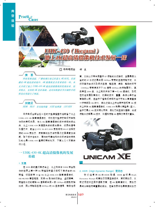
科技发展迅猛,广播电视行业已经进入4K 时代。
在演播室4K 超高清系统中,4K 摄像机是非常重要的一环。
本文介绍了池上UHK-430 4K 超高清摄像机的发展由来、技术特点、支持的4K 色彩基础,还对该机器在节目制作中的特色应用进行了阐述。
HDR HLG 非压缩传输 AXII 处理器 12G-SDI中央电视台新台址E 区的大型演播室已经配备了池上UHK-430 4K 超高清摄像机,该机在大型综艺电视节目制作中的表现优异。
作为4K 超高清摄像机技术领域的排头兵,池上UHK-430凭借其先进的感光器件、优异的信号处理芯片,配合以ITU R-BT.2020宽色域和HLG 伽玛支持的HDR 宽动态,使画面的动态细节层次还原得更加细腻。
除了技术性能外,操作的可靠性和升级改进后的特色功能也是UHK-430值得称赞的地方,下面从几个方面进行介绍。
一 UHK-430 4K 超高清摄像机的发展基础1. 发展在2016年的里约奥运会上,池上和日本NHK 联合制作的世界上第一辆8K 转播车就首次实现了奥运会的8K 转播。
该车配有10台8K 池上SHK-810超高清摄像机,8K/4K/HD 兼容矩阵,支持8K 制作的切换台、监视器等。
转播车系统的每路8K 信号都采用4根12Gbps 的铜制同轴线缆,用以传输非压缩48Gbps 的8K 图像信号,稳定性很当时的IP 系统还是采用10Gbps 带宽的压缩传输方式,系统中自然会涉及到很多压缩、解压缩、编码、解码的环节(10Gbps 带宽满足不了8K 信号48Gbps 的传输要求)。
其实早在2004年,池上就已开发了第一代8K 摄像机,到现在已经发展到第三代,机器的技术、重量、品质也早已全术上开发4K 超高清摄像机,UHK-430就是代表型号(图1)。
由于它是从8K 技术转化而来,因此它的图像处理器、光缆传输系统都是8K 技术,处理和传输4K 信号仍有很大富裕。
2. HDR (High Dynamic Range )宽动态我们经常说4K 的HDR 拍摄,HDR 全称是High Dynamic Range 即高动态范围图像技术,简称宽动态。

HLG的下半部分采用了侧重于中灰和暗部区域表现的SDR伽马;上半部分针对高光采用了对数LOG曲线。
在HDR发展之初,由于市面还存在着绝大多数SDR的电视机,电视广播面临的主要问题是,如何保证众多用户能够看到相对正确的HDR显示效果。
这就需要探索一种光与电之间的对应关系,能够兼容HDR和SDR的屏幕。
日本NHK电视台,英国广播E代表线性光的亮度电平值,与线性信号成正比。
E的范围为[0,1],是归一化处理之后的R、G、B值。
对于黑白灰图像(消色差图像),R=G=B=E。
E’表示转换后的电平值,是经过HLG混合对于是得到图5。
在图5中,HLG 的动态范围最大是320%,而不是1200%。
难道调整曝光会影响影像的动态范围?事实上,调整曝光会影响动态范围的分布。
当调整曝光让拍摄18%灰度卡的HLG 输出信号值为42.5%时,留给高光的动态范围320%,只有SDR 动态范围的3倍多。
高光的动态范围确实减少了,但是留给阴影暗部的动态范围增加了。
HDR,不仅是增加高光的亮度,在阴影暗部的渲染细节能力同样有大幅提升。
当输出信号电平值小于或等于50%时,HLG 和SDR 对线性光的响应很接近,只有微小的区别。
E’的范围为(0.5,1]。
当E=1/12时,E’=0.5,也就是50%。
在HLG 早期的相关文档中,认为HLG 曲线的“下半部分”也就从0到50%区间是SDR的部分。
50%的HLG电平,代表了SDR 的峰值(不含场景高光部分),也就是漫反射白(即100%SDR,也是HDR 的参考白)。
当E >1/12时,输出信号电平值大于50%,HLG 采用的是对数函数。
人的感知特性(例如人对光亮度的感知),即差别的阈值,会随着刺激量的变化而产生变化。
19世纪德国生理学家E.H.韦伯研究发现了韦伯定律:感觉量与物理量的对数值成正比,也就是说,人的感觉的增量,会落后于物理量的增加;物理量(光)成几何级数增长(成倍增加),心理量(对光明暗程度的感知)成算数级数增长(逐个增加)。
目前以高清SDR 为主的制播阶段,4K HDR 与SDR 的高质量兼容制作是业内关注的焦点。
本文从HDR 技术特征、HDR 与SDR 制作流程方面进行理论分析,并结合实际应用案例,探讨HDR 与SDR 协同制作质量控制手段,提出兼容制作需要关注的相关问题。
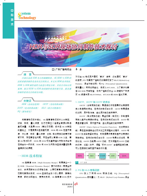
HDR (高动态范围) OETF (光电转换函数) EOTF (电光转换函数) HLG (混合对数伽玛)PQ (感知量化)与高清电视技术相比,4K 超高清电视技术从分辨率、帧率、色域、量化深度、动态范围五个维度全面提升影像呈现质量,尤其是HDR (高动态范围)技术在4K 分辨率的基础上,大幅度提升图像呈现度。
HDR 与SDR 在显示亮度、对比度、色域、量化深度、光电/电光转换函数等方面都不同,存在兼容性问题。
而在当前以高清SDR 为主,兼容4K 制作阶段,HDR 与SDR 现场直转播协同制作将会存在相当长一段时间,HDR 与SDR 协同制作图像质量控制是值得探讨的课题。
一 HDR 技术特征4K 超高清 HDR (High Dynamic Range )就是建立一个比SDR (Standard Dynamic Range )更大的色彩/亮度坐标体系,并使用新的系统传输函数,以再现更高的亮度动态范围和更宽的色域。
HDR 图像包含三个核心要素:更高的亮度、新的伽玛曲线、更宽的色域。
4K 超高清HDR 技术不仅给4K 电视用户展现“更多”像素,还能展现“更好”的像素。
ITU 和国家广播电视总局都规定了HLG (Hybrid-Log Gamma :混合对数伽玛)和PQ (Perceptual Quantization :感知量化)两种伽玛曲线,色域为BT.2020。
为了更好地兼容HD SDR 节目制播,中央广播电视总台4K 频道和广东综艺4K 频道采用HLG/1000nit 、BT.2020的HDR 播出方案。
OETF (光电转换函数)是摄像机中被摄景物光亮度转换为电信号的特性。

Speech CodingAbstract:Speech coders have assumed considerable importance in communication systems as their performance, to a large extent, determines the quality of the recovered speech and the capacity of the system. The goal of all speech coding systems is to transmit speech with the highest possible quality using the least possible channel capacity. The most basic property of speech waveforms that is exploited by all speech coders is that they are bandlimited. Adaptive differential pulse code modulation (ADPCM) is a more efficient coding scheme which exploits the redundancies present in the speech signal.performance evaluation of speech coders have objective measures and subjective listening tests.Key Words:Speech coders;possible channel capacity; bandlimited; performance evaluation1 IntroductionSpeech coders have assumed considerable importance in communication systems as their performance, to a large extent, determines the quality of the recovered speech and the capacity of the system. Especially in wireless communication system, bandwidth is a precious commodity, and service providers are continuously met with the challenge of accommodating more users within a limited allocated bandwidth. Low bit-rate speech coding offers a way to meet this challenge. The lower the bit rate at which the coder can deliver toll-quality speech, the more speech channels can be compressed within a given bandwidth. For this reason, manufacturers and service providers are continuously in search of speech coders that will provide toll quality speech at lower bit rates.The goal of all speech coding systems is to transmit speech with the highest possible quality using the least possible channel capacity. This has to be accomplished while maintaining certain required levels of complexity of implementation and communication delay. In general, there is a positive correlation between coder bit-rate efficiency and the algorithmic complexity required to achieve it. The more complex an algorithm is, the more its processing delay and cost of implementation. A balance needs to be struck between these conflicting factors, and it is the aim of all speech processing developments to shift the point at which this balance is made toward ever lower bit rates.Speech signals have two properties which can be used in speech processing:V oiced speech signal show during certaintime intervals almost periodic behavior. Therefore, we can consider these signals as quasi-stationary signals for around 30 milliseconds.The spectrum of audio signals shows characteristic maxima, which are mostly 3~5 frequency bands. These maxima, called formants, occur because of resonances of thevocal tract.Speech coders differ widely in their approaches to achieving signal compression. Based on the means by which they achieve compression, speech coders are broadly classified into two categories: waveform coders and vocoders. Waveform coders use algorithms to encode speech so that the system output is an approximation to the input waveform. V ocoders encode speech by extracting a set of parameters that are digitized and transmitted to the receiver, where they are used to set values for parameters in function generators and filters, which, in turn, synthesize the output speech sound. Usually, the vocoder output waveform does not approximate the input waveform and may have an artificial, unnatural sound. Although the words of the speaker may be clearly understandable, the speaker may not be identifiable. With waveform encoders (e.g., PCM, DPCM, DM, and CVSD), it was demonstrated that VF-quality speech may be encoded at bit rates as low as 24 kbps. More advanced techniques reduce the required bit rate to 8 kbps, and speech coding is possible even at 2 kbps. Some techniques that are available to achieve coders at low bit rates are linear prediction (discussed as applied to DPCM), adaptive subband coding, and vector quantization. Adaptive subband coding allocates bits according to the input speech spectrum and the properties of hearing. With vector quantization, whole blocks of samples are encoded at a time, instead of encoding on a sample-by-sample basis. Examples are code excited linear prediction (CLEP) and vector-sum excited linear prediction (VSELP), used in digital cellular telephones. These coders emoloy linear-prediction-based analysis-by-synthesis (LPAS) techniques, in which the talker's speech signal is partitioned into 20-ms segments for analysis and synthesis. The encoder sequences through the possible codebook excitation patterns and the possible values for the filter parameters ti find a synthesized waveform that gives the best match to a speech segment. The encoder parameters that specify this best match are then transmitted to the receiver via digital data. The received data establish the parameters for the receiver speech synthesizer so that the voice signal is reproduced for the listener.One strive to use lower bit-rate codecs in order to reduce data transmission costs. However, lower bit-rata codecs require greater computation complexity, produce longer delays of the reproduced speech at the system output, and have poorer speech quality.2 Characteristics of Speech signalsSpeech waveforms have a number of useful properties that can be exploited when designing efficient coder. Some of the properties that are most often utilized in coder design include the nonuniform probability distribution of speech amplitude, the nonzero autocorrelation between successive speech samples, the nonflat nature of the speech spectra, the existence of voiced and unvoiced segments in speech, and the quasiperiodicity of voiced speech signals. The most basic property of speech waveforms that is exploited by all speech coders is that they are bandlimited. A finite bandwidth means that it can be time-discretized (sampled) at a finite rate and reconstructed completely from its samples, provided that the sampling frequency isgreater than twice the highest frequency component in the low pass signal. While the band limited property of speech signals makes sampling possible, the aforementioned properties allow quantization, the other most important process in speech coding, to be performed with greater efficiency.3 Adaptive Differential Pulse Code Modulation (ADPCM) Pulse code modulation systems do not attempe to remove the redundancies in the speech signal. Adaptive differential pulse code modulation (ADPCM) is a more efficient coding scheme which exploits the redundancies present in the speech signal. As mentioned earlier, adjacent samples of a speech waveform are often highly correlated. This means that the variance of the difference between adjacent speech amplitudes is much smaller than the variance of the speech signal itself, ADPCM allows speech to be encoded at a bit rate of 32 kbps, which is half the standard 64 kbps PCM rate, while retaining the same voice quality. Efficient algorithms for ADPCM have been developed and standardized. The CCITT standard G.721 ADPCM algorithm for 32 kbps speech coding is used in cordless telephone systems.In a differential PCM scheme, the encoder quantizes a succession of adjacent sample differences, and the decoder recovers an approximation to the original speech signal by essentially integrating quantized adjacent sample differences. Since the quantization error variance for a given number of bits/sample R, is directly proportional to the input variance, the reduction obtained in the quantizer input variance leads directly to a reduction of reconstruction error variance for a given value of R.In practice, ADPCM encoders are implemented using signal prediction techniques. Instead of encoding the difference between adjacent samples, a linear predictor is used to predict the current sample. The difference between the predicted and actual sample called the prediction error is then encoded for transmission. Prediction is based on the knowledge of the autocorrelation properties of speech.4 Frequency Domain Coding of SpeechFrequency domain coders are a chass of speech coders which take advantage of speech perception and generation models without making the algorithm totally dependent on the models used. In this class of coders, the speech signal is divided into a set of frequency components which are quantized and encoded separateky. In this way, different frequency bands can be preferentially encoded according to some perceptual criteria for each band, and hence the quantization noise can be contained within bands and prevented from creating harmonic distortions outside the band. These schemes have the advantage that the number of bits used to encode each frequency component can be dynamically varied and shared among the different bands.Many frequency domain coding algorithms, ranging from simple to complex are available. The most common types of frequency domain coding include sub-band coding (SBC) and block transform coding. While a sub-band coder drvides the speech signal into many smaller sub-bands and encodes each sub-band separately accordingto some perceptual criterion, a transform coder the short-time transform of a windowed sequence of samples and encodes them with number of bits proportional to its perceptual significance.5 Performance Evaluation of Speech CodersThere are two approaches to evaluating the performance of a speech coder in terma of itsability to preserve the signal quality. Objective measures have the general nature of a signal-to-noise ratio and provide a quantitative value of how well the reconstructed speech approximates the original speech. Mean square error (MSE) distortion, frequency weighted MSE, and segmented SNR, articulation index are examples of objective measures. While objective measures are useful in initial design and simulation of coding system, they do not necessarily give an indication of speech quality as perceived by the human ear. Since the listener is the ultimate judge of the signal quality, subjective listening tests constitute an integral part of speech coder evaluation.Subjective listening tests are conducted by playing the sample to a number of listeners and asking them to judge the quality varies with the age and gender of the speaker, the speed at which the speaker speaks, and other factors. The subjective tests are carried out in different environments to simulate real life conditions such as noisy, multiple speakers, etc., these tests provide results in terms of overall quality, listening effort, intelligibility, and naturalness. The intelligibility tests measure the listeners abliity to identify the spoken word. The diagnostic rhyme test (DRT) is the most popular and widely used intelligibility test. In this test, a word from a pair of rhymed words such as "thosedose" is presented to the listener and the listener is asked to identify which word was spoken. Typical percentage correct on the DRT test ranges from 75~90. The diagnostic acceptability measure (DAM) is another test that evaluates acceptability of speech coding systems. All these tests results are difficult to rank and hence require a reference system. The most popular ranking system is known as the mean opinion score or MOS ranking. This is a five point quality ranking scale with each point associated with a standardized descriptions: bad, poor, fair, good, excellent.。
基于异质性分类的小波域SAR图像去斑侯建华;陈稳;刘欣达;陈少波【摘要】A Bayesian wavelet speckle reduction algorithm for SAR image is developed under the non-homomorphic framework. We use Normal Inverse Gaussian (NIG) function for modeling backscattered signal in wavelet domain, and Gaussian function for speckle noise (i.e. signal-dependent noise). The estimation formula of noise-free signal is derived by Bayesian maximum a posteriori (MAP) criterion. With regarding to estimation of model parameters, we introduce Multiscale Local Coefficient of Variation (MLCV) as heterogeneity measure, the histogram of which can be well fitted by logarithmic normal distribution. Based on heterogeneity measure, each coefficient in wavelet sub-band is classified into one of several different heterogeneity scenes, and NIG model parameters are computed in each class through cumulants estimation method. Experiment results show that, compared with its counterpart algorithm in homomorphic framework and its counterpart algorithm in non-homomorphic framework without heterogeneity based classification, our method has obvious advantage in terms of both subjective and objective evaluation, and has obtained satisfactory de-speckled image. A classification method of wavelet coefficients is proposed by heterogeneity measure, which could provide a new means for the research of SAR image despeckling.%提出了一种非同态滤波框架下的小波域SAR图像相干斑抑制算法。
第二篇压缩与编码数字信号的压缩与编码是多媒体的核心技术和重要内容。
第3章中所讲的,音频信号的自适应编码、差分编码和预测编码等,都是典型的压缩编码。
本篇先介绍压缩的基本概念,再讲解可用于静态图像编码的若干常用熵编码压缩算法、基于DCT的JPEG编码、运动图像和伴音的MPEG编码压缩算法、以及当前十分热门的AVC 和AVS编码。
本篇分为如下5章:n 第7章压缩与熵编码n 第8章JPEG编码n 第9章MPEG编码n 第10章H.264/AVC编码n 第11章AVS视频编码多媒体技术基础• 2 •第7章 压缩与熵编码由于多媒体信号的数据量巨大,为了节省存储空间和传输带宽,需进行压缩编码。
多媒体数据的压缩方法,可以分成三大类,其中的熵编码是基础,源编码是重点,而将它们二者相结合的混合编码则是各种编码标准所采用的主要方法。
本章先介绍压缩的基本概念,包括:压缩的需要与可能、算法的特点与分类和一般的编码过程。
然后,在了解熵定义的基础上,讨论若干常用的熵编码算法,包括:Shannon-Fano 编码、Huffman 编码、算术编码、RLE 和可用于GIF 图像编码的LZW 算法。
7.1 压缩概论数据压缩(data compression) ,在电子与通信领域也常被称为信号编码(signal coding),包括压缩和还原(或编码和解码)两个步骤,相关概念的英文单词参见表7-1。
与压缩相关的学科有:信息论、数学、信号处理、数据压缩、编码理论和方法。
7.1.1 压缩的需要与可能由于多媒体信号的数据量巨大,所以需要压缩;同时,由于在多媒体数据中,存在着各种冗余,所以可以压缩。
l 压缩的需要数据量巨大是多媒体信号的特点,例如:n 一幅1024*1024真彩图:1024行 * 1024列 * 3B 彩色 = 3MBn 5分钟的CD 音乐:44100样本 / 秒 * 2B(16b) / 样 * 2声道 * 60秒 * 5分钟 =50.47MBn 90分钟的PAL 视频:625行 * 864列 * 3B 彩色 * 25帧 / 秒 * 60秒 * 90分 = 203.68GB为了节省存储空间(如VCD/DVD 、JPEG/MP3/MP4、多媒体数据库)和传输带宽(HDTV 、因特网、流媒体),以进行实时高质的多媒体通信(如视频/音频点播、网络现场直播、可视电话、视频会议),必须对多媒体数据进行压缩编码。
Recommendation ITU-R BT.2100-0(07/2016) Image parameter values for high dynamic range television for use in production and international programme exchangeBT SeriesBroadcasting service(television)ii Rec. ITU-R BT.2100-0ForewordThe role of the Radiocommunication Sector is to ensure the rational, equitable, efficient and economical use of the radio-frequency spectrum by all radiocommunication services, including satellite services, and carry out studies without limit of frequency range on the basis of which Recommendations are adopted.The regulatory and policy functions of the Radiocommunication Sector are performed by World and Regional Radiocommunication Conferences and Radiocommunication Assemblies supported by Study Groups.Policy on Intellectual Property Right (IPR)ITU-R policy on IPR is described in the Common Patent Policy for ITU-T/ITU-R/ISO/IEC referenced in Annex 1 of Resolution ITU-R 1. Forms to be used for the submission of patent statements and licensing declarations by patent holders are available from http://www.itu.int/ITU-R/go/patents/en where the Guidelines for Implementation of the Common Patent Policy for ITU-T/ITU-R/ISO/IEC and the ITU-R patent information database can also be found.Electronic PublicationGeneva, 2016ITU 2016All rights reserved. No part of this publication may be reproduced, by any means whatsoever, without written permission of ITU.Rec. ITU-R BT.2100-01 RECOMMENDATION ITU-R BT.2100-01Image parameter values for high dynamic range television foruse in production and international programme exchange(2016) ScopeHigh Dynamic Range Television (HDR-TV) provides viewers with an enhanced visual experience by providing images that have been produced to look correct on brighter displays, that provide much brighter highlights, and that provide improved detail in dark areas. This Recommendation specifies HDR-TV image parameters for use in production and international programme exchange using the Perceptual Quantization (PQ) and Hybrid Log-Gamma (HLG) methods.KeywordsHigh dynamic range, HDR, television, HDR-TV, image system parameters, television production, international programme exchange, wide colour gamut, perceptual quantization, PQ, hybrid log-gamma, HLGThe ITU Radiocommunication Assembly,consideringa)that digital television image formats for HDTV and UHDTV have been specified by the ITU-R in Recommendations ITU-R BT.709 and ITU-R BT.2020;b)that these television image formats have been limited in the image dynamic range they can provide due to their reliance on legacy cathode ray tube (CRT) characteristics that limit image brightness and detail in dark areas;c)that modern displays are capable of reproducing images at a higher luminance, greater contrast ratio and wider colour gamut than is conventionally employed in programme production; d)that viewers expect future television viewing to provide improved characteristics compared with the current HDTV and UHDTV in terms of a more realistic sensation, greater transparency to the real world and more accurate visual information;e)that high dynamic range television (HDR-TV) has been shown to increase viewer enjoyment of television pictures;f)that HDR-TV provides a “step-change” improvement in viewer experience by means of substantially increased brightness and detail in highlights and diffuse reflecting objects, while providing greater detail in dark areas;g)that the combination of extended dynamic range and extended colour gamut give HDR-TV a substantially larger colour volume;h)that the HDR-TV image formats should have, where appropriate, a degree of compatibility with existing workflows and infrastructure;1The Administrations of France and the Netherlands have expressed concerns regarding the characteristics and performance of HDR-TV. Further studies are needed and may lead to a revision of this Recommendation, as appropriate, under the terms of Resolution ITU-R 1-7.2Rec. ITU-R BT.2100-0i)that a reference viewing environment including display parameters should be defined for HDR-TV image formats,further consideringthat due to rapid developments in HDR technology the ITU may wish to consider early updates and improvements to this Recommendation,recognizingthat Report ITU-R BT.2390 contains much information on two methods to achieve HDR-TV, recommendsthat for programme production and international exchange of HDR-TV, the perceptual quantization (PQ) or Hybrid Log-Gamma (HLG) specifications described in this Recommendation should be used. NOTE – The PQ specification achieves a very wide range of brightness levels for a given bit depth using a non-linear transfer function that is finely tuned to match the human visual system. The HLG specification offers a degree of compatibility with legacy displays by more closely matching the previously established television transfer curves. Conversion between these formats may be accomplished using the approach illustrated in informative Annex 2.TABLE 1Image spatial and temporal characteristicsNOTE 1a – Container is used to define the horizontal and vertical constraints of the image format.NOTE 1b –Productions should use the highest resolution image format that is practical. It is recognized that in many cases high resolution productions will be down-sampled to lower resolution formats for distribution. It is known that producing in a higher resolution format, and then electronically down-sampling for distribution, yields superior quality than producing at the resolution used for distribution.Rec. ITU-R BT.2100-03TABLE 2System colorimetryTable 3 specifies parameters to establish a reference viewing environment for critical viewing of HDR programme material or completed programmes that can provide repeatable results from one facility to another when viewing the same material. Viewing facilities can and will continue to be established in many ways by entities involved in editing, colour correction, screening and the like, and the specifications in this Table are not intended to suggest a need for absolute uniformity in such facilities.TABLE 3Reference viewing environment for critical viewing of HDR programme materialNOTE 3a – Background and Surround are defined in CIE 159:2004 "A Colour Appearance Model for Colour Management Systems: CIECAM02".NOTE 3b – When picture evaluation involves resolution, the lower value of viewing distance should be used. When resolution is not being evaluated, any viewing distance in the indicated range may be used.NOTE 3c – This is not to imply this brightness must be achieved for full screen white, rather for small area highlights.NOTE 3d – Actual black level would be set using a PLUGE signal and may differ from the indicated value.4Rec. ITU-R BT.2100-0Tables 4 and 5 describe transfer functions for the PQ and HLG formats, respectively. High dynamic range television production and display should make consistent use of the transfer functions of one system or the other and not intermix them. Informative Annex 1 illustrates the meaning of the various transfer functions and where they are used in the signal chain. Informative Annex 3 provides information on alternate equations that could facilitate implementation of these transfer functions.TABLE 4PQ system reference non-linear transfer functionsRec. ITU-R BT.2100-05TABLE 4 (end)NOTE 4a – This same non-linearity (and its inverse) should be used when it is necessary to convert between the non-linear representation and the linear representations.NOTE 4b–In this Recommendation, when refering to the luminance of a single colour component (R D, G D, B D), it means the luminance of an equivalent achromatic signal with all three colour components having that same value.TABLE 5Hybrid Log-Gamma (HLG) system reference non-linear transfer functions6Rec. ITU-R BT.2100-0TABLE 5 (cont.)Rec. ITU-R BT.2100-07TABLE 5 (end )NOTE 5a – The inverse of this non-linearity should be used when it is necessary to convert between the non-linear representation and the linear representation of scene light.NOTE 5b – If E is normalized to the range [0:1] then the equivalent equation for the OETF is:[]()⎩⎨⎧<+-⋅≤≤=='Ecb E a E EE E 121121ln 03OETFwhere a = 0.17883277, b = 0.02372241, c = 1.00429347NOTE 5c – If E is normalized to the range [0:1] then the equivalent equation for the E is:[]()()⎩⎨⎧'<+-'≤'≤'='=-E ba c E E E E E 212121/exp 03OETFwhere a , b and c are as defined in Note 5b.NOTE 5d – This EOTF applies gamma to the luminance component of the signal, whereas some legacy displaysmay apply gamma separately to colour components. Such legacy displays approximate this reference OOTF. NOTE 5e – For displays with nominal peak luminance (L W ) greater than 1000 cd/m 2, or where the effective nominal peak luminance is reduced through the use of a contrast control, the system gamma value should be adjusted according to the formula below, and may be rounded to three significant digits:()1000Log 0.422.1γ10W L +=NOTE 5f – The system gamma value may be decreased for brighter background and surround conditions. NOTE 5g – When E is normalized to the range [0:1] then the equation for α is:()B W L L -=αNOTE 5h – During production, signal values are expected to exceed the range E ′ = [0.0 : 1.0]. This provides processing headroom and avoids signal degradation during cascaded processing. Such values of E ′, below 0.0 or exceeding 1.0, should not be clipped during production and exchange. Values exceeding 1.0 should not be shown on reference displays. Values below 0.0 should not be clipped in reference displays (even though they represent “negative” light) to allow the black level of the signal (L B ) to be properly set using test signals known as “PLUGE” (see Recommendation ITU-R BT.814).8Rec. ITU-R BT.2100-0Tables 6 and 7 describe different luminance and colour difference signal representations, suitable for colour sub-sampling, and/or source coding. The Non-Constant Luminance (NCL) format is in widespread use and is considered the default. The Constant Intensity (CI) format is newly introduced in this Recommendation and should not be used for programme exchange unless all parties agree.TABLE 6Non-Constant Luminance Y'C'B C'R signal format6aNOTE 6a–For consistency with prior use of terms, Y',C'B and C'R employ prime symbols indicating they have come from non-linear Y, B and R.TABLE 7Constant Intensity IC T C P signal format7a, 7bNOTE 7a–The newly introduced I, C T and C P symbols do not employ the prime symbols to simplify the notation.NOTE 7b –Colours should be constrained to be within the triangle defined by the RGB colour primaries in Table 2.NOTE 7c–The subscripts D and S refer to display light and scene light, respectively.Colour sub-samplingTable 9 describes two different signal representations, “narrow” and “full”. The narrow range representation is in widespread use and is considered the default. The full range representation is newly introduced in this Recommendation and should not be used for programme exchange unless all parties agree.Digital 10- and 12-bit integer representationNOTE 9a–10-bit values of E > 1023/1024 cannot be represented. For consistency, 12-bit values are thus clipped to the value 4092/4096.NOTE 9b – Signals may extend below black (sub-blacks) and exceed the nominal peak values (super-whites), but shall not exceed the video data range.NOTE 9c – Narrow range values outside of the video data range are used for timing signals on some interfaces, and thus should not be used. Full range signals may be clipped to the narrow video data range when conveyed over such interfaces.Table 10 introduces a 16-bit floating point signal representation. Currently, real-time interfaces do not exist for this format. It is expected that this format would initially see usage in file-based workflows and programme exchange.TABLE 10Floating Point (FP) signal representationAnnex 1(Informative)The relationship between the OETF, the EOTF and the OOTFThis Recommendation makes extensive use of the following terms:OETF: t he opto-electronic transfer function, which converts linear scene light into the video signal, typically within a camera.EOTF: e lectro-optical transfer function, which converts the video signal into the linear light output of the display.OOTF: opto-optical transfer functi on, which has the role of applying the “rendering intent”.These functions are related, so only two of the three are independent. Given any two of them the third one may be calculated. This section explains how they arise in television systems and how they are related.In television systems the displayed light is not linearly related to the light captured by the camera. Instead an overall non-linearity is applied, the OOTF. The “reference” OOTF compensates for difference in tonal perception between the environment of the camera and that of the display. Specification and use of a “reference OOTF” allows consistent end-to-end image reproduction, which is important in TV production.Artistic adjustment may be made to enhance the picture. These alter the OOTF, which may then be called the “artistic OOTF”. Artistic adjustment may be applied either before or after the reference OOTF.In general the OOTF is a concatenation of the OETF, artistic adjustments, and the EOTF.The PQ system was designed with the model shown below, where the OOTF is considered to be in the camera (or imposed in the production process).The HLG system was designed with the model shown below, where the OOTF is considered to be in the display.Only two of three non-linearities, the OETF, the EOTF, and the OOTF, are independent. In functional notation (where subscripts indicate the colour component):()()()()()()()()()B G R B G R B G R B G R B G R B G R B B B G G G R R R ,,OETF EOTF ,,OOTF ,,OETF EOTF ,,OOTF ,,OETF EOTF ,,OOTF === This is clearer if the concatenation is represented by the symbol ⊗. With this notation, the followingthree relationships between these three non-linearities are obtained:111111111OOTF EOTF OETF OETF OOTF EOTF OETF EOTF OOTF EOTF OOTF OETF OOTF OETF EOTF EOTF OETF OOTF ---------⊗=⊗=⊗=⊗=⊗=⊗=The PQ approach is defined by its EOTF. For PQ, the OETF may be derived from the OOTF using the third line of the equations above. In a complementary fashion the HLG approach is defined by its OETF. For HLG, the EOTF may be derived from the OOTF using the second line of the equations above.(Informative)Conversion between HLG and PQ signalsThe following diagram illustrates conversion from the PQ signal to the HLG signal. The signal processing is that the PQ signal is decoded by the PQ EOTF to yield a signal that represents linear display light. This signal is then encoded by the HLG inverse EOTF to produce an equivalent HLG signal. When this HLG signal is subsequently decoded by the HLG EOTF in the display, the result will be the same display light that would be produced by decoding the original PQ signal with the PQ EOTF. The HLG inverse EOTF is the HLG inverse OOTF followed by the HLG OETF. For the HLG inverse OOTF, black level should be zero, and the gamma parameter is determined by the peak level of the PQ signal.The following diagram illustrates conversion from the HLG signal to the PQ signal. The signal processing is that the HLG signal is decoded by the HLG EOTF to yield a signal that represents linear display light. This signal is then encoded by the PQ inverse EOTF to produce an equivalent PQ signal. When this PQ signal is subsequently decoded by the PQ EOTF in the display, the result will be the same display light that would be produced by decoding the original HLG signal with the HLG EOTF. For the HLG EOTF, black level should be zero, and the gamma may be set to the value specified in Table 5 (presuming peak luminance of 1 000 cd/m2).(Informative)Parametric representation of electro-optical andopto-electronic transfer functionsThis Annex in connection with appropriate parameter sets facilitates the implementation of the reference opto-electronic transfer functions (OETFs), as well as the reference electro-optical transfer functions (EOTFs) of this Recommendation. An EOTF may be represented by equation (1):()()ns m V st m V c V L /1⎪⎭⎫ ⎝⎛----= (1)where: V : nonlinear colour valueL : corresponding linear colour value. The parameter set {s , t , c , n , m } can be set according to a desired application. An OETF may be represented by equation (2):()m stL csL L V n n +++=(2)It should be noted that if the parameters s , t , c , n and m are given identical values in equations (1) and (2), then L(V) and V(L) are the mathematical inverse of each other.In certain applications, it is helpful to normalize V in equations (1) and (2) according to equation (3):m kp V V+-=ˆ (3)where: V : non-linear colour valueVˆ: normalized non-linear colour value that replaces V in equations (1) and (2). The parameters k and p can be set according to a desired application.In certain applications, it is helpful to normalize L in equations (1) and (2) according to equation (4):ab L L-=ˆ (4)where:L : linear colour valueLˆ: normalized linear colour value that replaces L in equations (1) and (2). The parameters a and b can be set according to a desired application.______________。
用于图像认证的小波域量化盲水印算法马列红;王冰【期刊名称】《计算机工程与应用》【年(卷),期】2011(047)009【摘要】A semi-fragile watermarking algorithm for image authentication is proposed. Edge-character is extracted by finding the maxima of a wavelet transform modulus. Low frequency character is generated by wavelet transform for another watermark. One watermark is used for indicating the modified location and another is used for checking content modification. Watermarks are embedded in the coefficients of middle frequency of wavelet transform.Image authentication and watermark extract need no information about the original watermark. Experimental results show that the proposed algorithm provides good classification of intentional and incidental tampering.%提出了一种用于图像内容认证的半脆弱水印算法.该算法利用小波变换模极大值提取图像边缘特征,并结合经混沌映射后的小波低频域特征信息生成两个水印.一个主要用于篡改定位,另一个主要用于检测图像的内容篡改.水印嵌入在小波变换的中频域中.水印提取和认证不需要原始水印信息,提高了水印安全性.实验表明,该算法能有效区分偶然失真和恶意篡改,并能定位出篡改发生的位置.【总页数】5页(P188-191,232)【作者】马列红;王冰【作者单位】西北大学,信息科学与技术学院,西安,710127;西北大学,信息科学与技术学院,西安,710127【正文语种】中文【中图分类】TP391【相关文献】1.基于Arnold置乱的小波域盲水印量化改进算法 [J], 卢琼2.适用于JPEG图像认证的脆性盲水印算法 [J], 范成博;张春田3.一种用于图像认证的二维DCT彩色图像盲水印新算法 [J], 李大力;马燕4.基于SVD的小波域自适应量化盲水印算法 [J], 罗竞毅;费耀平5.用于图像认证的小波域双重脆弱水印算法研究 [J], 李占德;张政保;文家福;黄子龙因版权原因,仅展示原文概要,查看原文内容请购买。
PERCEPTUAL QUANTIZATION FOR WA VELET-BASED IMAGE CODINGMarcia G.Ramos and Sheila S.HemamiSchool of Electrical EngineeringCornell UniversityIthaca,NY14853ABSTRACTA psychovisually-based quantization strategy for wavelet coded images is proposed.The quantization strategy is based on the results of a psychovisual evaluation to quantify sensi-tivities to suprathreshold distortion caused by wavelet coef-ficient quantization in natural images.Quantizer step sizes to produce a minimum noticeable distortion are paremeter-ized in terms of subband standard deviation and a quan-tization strategy is subsequentely proposed.The resulting strategy is applied to both intraband and embedded wavelet coders and reveals a significant perceptual improvement when images exhibit supra-threshold distortion.1.INTRODUCTIONPrevious work to develop perceptually-based quantization strategies for wavelet coding has been geared towards pro-viding visually lossless or sub-threshold compression[1], [2].When compression artifacts become visible and the compression algorithm is operating in the supra-threshold regime,the most common approach in the literature is to simply scale the quantization resulting from applying the perceptual model derived for sub-threshold compression.This approach,however,does not necessarily guarantee visually optimal images at supra-threshold compression.In this paper,a psychovisually-based quantization strat-egy for supra-threshold coded images is proposed,follow-ing an extensive psychophysical investigation of distortion visibilities caused by wavelet coefficient quantization.The psychophysical experiment was designed to include spa-tial masking,and the stimuli consisted of natural images in which wavelet coefficients in individual subbands(i.e., with specific frequencies and orientations)were quantized. Images were selected based on different characteristics,and the influence of each image characteristic on the resulting step sizes was analyzed.Quantizer step sizes to produce a minimum noticeable distortion are paremeterized in terms of subband standard deviation and a quantization strategy is subsequentely proposed.This strategy results in signifi-cant perceptual improvement of wavelet-coded images with supra-threshold distortion when compared to adapting sub-threshold models.This paper is organized as follows.Section2describes the psychovisual evaluation of supra-threshold wavelet quan-tization.Section3presents the quantization strategy based on the psychovisual evaluation results.The quantization strategy is applied to both an intra-band and embedded wavelet coder in Section4,and the paper is concluded in Section5.2.PSYCHOVISUAL EV ALUATION OF SUPRA-THRESHOLD W A VELET QUANTIZATION Human visual system sensitivities to supra-threshold wavelet quantization noise in natural images have been recently char-acterized in an extensive psychophysical evaluation described in[3].The relevant issues regarding quantization step sizes and relative sensitivity to distortion in different subbands are briefly discussed here to motivate the quantization strat-egy presented in the next section.Consider an image and its-level hierarchicalwavelet decomposition.Define as the reference image, in which a single subband is quantized with step sizeand the remaining subbands are left unquantized.Define as the distorted image,in which the same subband is quantized with step size,and the remaining sub-bands are unquantized;that is,the only difference between and is the additional quantization noise in caused by using a larger step size in the quantized subband.is called a minimum noticeable distortion step size(MNDSS) with respect to if an observer can visually distinguish a difference between and,but no noticeable difference is caused by step sizes with.The noticeable difference is called a visual distortion unit(VDU),andand are said to differ by one VDU.The psychophysical experiment determined a series of MNDSS(MNDSS)for each subband in an image.First, define as the stimulus image,quantized with.MNDSS for a single observer are determined as follows:Select a subband to evaluate.Let be the original image, ,.Initialize as and as.(i)Increase until a VDU is observed between and.(ii)Set MNDSS and so.(iii)If(where are the coefficients in subband at location),exit.(iv)else,proceed to step(i).That is,MNDSS causes one VDU between the original image and the quantized image,MNDSS is determined with respect to MNDSS,with the images quantized using MNDSS and MNDSS differing by one VDU,and so on. The MNDSS series were determined for15images(using a 5-level9/7wavelet decomposition)for150observers.The analysis in[3]indicates that MNDSS can befit by a regression equation of the formMNDSS(1) where and,and is the standard deviation of the subband that when quantized with MNDSS. Regression equations for MNDSS with differ in the parameter but varies only within4%.This indicates that a constant multiplicative of MNDSS for any subband can be used to achieve more VDUs.Contrast sensitivity functions given in[3]indicate orien-tation specificity,in addition to the well-accepted fact that sensitivity decreases with increasing spatial frequency.In scales with a skewed energy distribution(over50%of the energy in the scale was in either the LH or HL band),sen-sitivity was higher to the band with the higher energy,indi-cating that visual masking is a function of the energy in the band.Both the MNDSS parameterization and the contrast sensitivity results are used in developing the subband-based quantization strategy proposed in the next section.3.PERCEPTUAL QUANTIZATION STRATEGY The perceptual quantization strategy proposed is based on the psychovisual evaluation results which suggest that quan-tization step sizes are a function of subband energy.The MNDSS parameterization given in Equation1provides quan-tization step sizes to achieve one VDU when a single sub-band is quantized.In a practical compression algorithm, however,all subbands are quantized simultaneously and a combination of step sizes must be selected.If coefficients from multiple bands are quantized simul-taneously with their respective MNDSS,supra-threshold error pooling occurs,resulting in considerably higher visual distortion.Sub-threshold error pooling is usually modeled using aMinkowski sum that assumes that the individual error con-tributions are additive and produce an overall error that may be at or above threshold[4].Supra-threshold error pool-ing effects are,however,undocumented in the literature and there is no guarantee that a Minkowski model is appropriatein this case.In order to produce an image that has a single VDU when all the subbands are quantized,the VDU must be dis-tributed across all the bands.The approach advocated hereis to select the step sizes such that the fraction of the VDU contributed by each band is inversely proportional to the band energy.Assuming that MNDSS producesin visual distortion,where,each subband is quan-tized with a step size according to(3)The above quantization strategy is applicable to codingat afixed bit rate to achieve a visual distortion of1VDU. However,the multiplicative scaling observed between MNDSS and higher-induced MNDSS indicates that MNDSS can simply be scaled for all subbands to achieve higher visual distortion levels.4.APPLICATION TO COMPRESSION4.1.Intra-band subband codingThe proposed perceptual quantization strategy was used in a simple intra-band subband coder,with run-length and Huff-man coding.Figure1shows sailboat compressed at0.2 bpp with the quantization step sizes given in[1],and with the proposed quantization strategy.The step sizes given in [1]were originally proposed for the sub-threshold regime, and were multiplied by a constant to achieve the desired compression ratio.The images in Figure1show a signif-icant perceptual improvement with the proposed quantiza-tion strategy.In general,the proposed quantization strategy results in fewer noticeable artifacts in the smooth areas of the image and better preservation of edges than from the model in[1],as observed in sailboat.Higher compression at the same perceptual quality is possible when compared with the step sizes resulting from [1].Table I shows bit rate savings for images in the USC database by matching the perceptual quality to the model in [1]at0.15bpp.Image22%18%16%15%17%,where is the wavelet co-efficient at band and position,is the coding pass,and is the initial coding threshold,i.e.,max [5].Different quantization step sizes other than can be adapted for each band by either modifying the thresh-old for each band during the embedding process[6],or by multiplying the subband coefficients by a visual weight prior to the embedded coding,resulting in an effective step size of as in[7]and[8].The second and more common approach is also more efficient in terms of encod-ing/decoding complexity,and is adopted here.Subband-specific step sizes are therefore achievable by using subband-specific weights,and the appropriate scaled MNDSS step sizes are achieved with a weighting of(4) where is a normalization factor.Because and are con-stant for all subbands,they do not affect the relative subband scalings and can be omitted from the weighting.In this pa-per,is chosen so that the highest visual weight assigned to any band is equal to2.A visual weight is not applied to the LL band as it is treated separately and codedfirst by embed-ded coders.The normalization factor is used only to change the coding order of the high-frequency coefficients relative to the LL band,which has an effect on the visual quality of images coded at very low bit rates.According to previous HVS research and as shown by the psychophysical evaluation in[3],the activity content of an image region influences the HVS sensitivity to quantiza-tion noise and image recognition.The subband-based visual weights described above can be multiplied by activity-based visual weights that depend on the activity content of an image region,classified into smooth,edge,or detailed. The weights are applied to facilitate rapid image recog-nition by emphasizing edge information,force more com-pression artifacts into detailed regions where they are less likely to be noticed,and minimize compression artifacts in smooth regions.Visual weights are applied to the SPIHT algorithm for barbara coded at0.2bpp with4decomposition levels in Figure2.Thefigure shows perceptual gains in the smooth and edge regions of the image at the expense of detailed regions.The edges around the table and barbara’s shoulder, as well as her face are much sharper with the use of visual weights.5.CONCLUSIONSThis paper presents a perceptual quantization strategy for wavelet-based coders that achieves higher quality images than previously proposed perceptual models.The quantiza-tion strategy was developed after an extensive psychovisual evaluation to quantify sensitivities to supra-threshold dis-tortion caused by wavelet coefficient quantization.Visual gains are especially significant around0.2-0.3bits/pixel,when the images clearly show artifacts.Results show that per-ceived image quality can be improved even when coding artifacts are visible.6.REFERENCES[1] A.B.Watson,G.Y.Yang,J.A.Solomon,and J.Villasenor,“Visibil-ity of wavelet quantization noise”,IEEE Trans.Image Processing,vol.6,no.8,pp.1164-1175,August1997.[2]R.J.Safranek and J.D.Johnston,“A perceptually tuned sub-band image coder with image dependent quantization and post-quantization data compression”,Proc.IEEE ICASSP,vol.3,pp.1945-1948,New York,NY,May1989.[3]S.S.Hemami and M.G.Ramos,“Wavelet coefficient quantizationto produce equivalent visual distortions in complex stimuli”,Pro-ceedings SPIE Human Vision and Electronic Imaging V,San Jose,CA,January2000.[4] A.B.Watson,“DCT quantization matrices visually optimized forindividual images”,Proceedings SPIE Human Vision,Visual Pro-cessing,and Digital Display,pp.202-216,San Jose,CA,February1993.[5] A.Said and W.Pearlman,“A new fast and efficient image codecbased on set partitioning in hierarchical tress”,IEEE Transactionson Circuits and Systems for Video Technology,V ol.6,No.6,pp.243-250,June1996.[6]J.Li and S.Lei,“Embedded still image coder with rate-distortionoptimization”,Proceedings SPIE Visual Communications and Im-age Processing,V ol.3309,pt.2,pp.36-47,San Jose,CA,January1998.[7]I.Hontsch,L.J.Karam,and R.J.Safranek,“A perceptually tunedembedded zerotree image coder”,Proceedings IEEE International Conference on Image Processing ,V ol.1,pp.41-4,Santa Barbara,CA,October 1997.[8]S.Daly,W.Zeng,and J.Li,“Visual masking in wavelet compressionfor JPEG 2000”,Proceedings SPIE Image and Video Communica-tions and Processing ,San Jose,CA,January2000.(a)(b)Fig.1.sailboat at 0.2bpp.(a)Scaled step sizes from [1].(b)Proposed.(a)(b)Fig.2.barbara at 0.2bpp.(a)SPIHT.(b)Visual weights applied to SPIHT.。