磨刀机中文说明书
- 格式:docx
- 大小:469.52 KB
- 文档页数:30
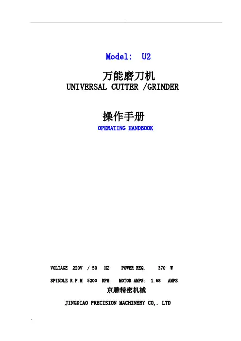
Model: U2万能磨刀机UNIVERSAL CUTTER /GRINDER操作手册OPERATING HANDBOOKVOLTAGE 220V / 50 HZ POWER REQ. 370 WSPINDLE R.P.M 5200 RPM MOTOR AMPS: 1.68 AMPS京雕精密机械JINGDIAO PRECISION MACHINERY CO,. LTD目录附件说明------------------------------------------------------------------------------------------------------------------------------------------1砂轮主轴------------------------------------------------------------------------------------------------------------------------------------------2分度头托架保养---------------------------------------------------------------------------------------------------------------------------------2修整砂轮------------------------------------------------------------------------------------------------------------------------------------------3刀具外形-刀具角度-切销速度----------------------------------------------------------------------------------------------------------------3刀具切销速度------------------------------------------------------------------------------------------------------------------------------------3用砂轮定刀刃中心------------------------------------------------------------------------------------------------------------------------------4斜切削刃刀具前角的外圆磨法---------------------------------------------------------------------------------------------------------------5端切削刃(直线)刀具前角的外圆磨法-------------------------------------------------------------------------------------------------------5端切销刃(圆形)刀具前角的外圆磨法-------------------------------------------------------------------------------------------------------6磨尖头刀具---------------------------------------------------------------------------------------------------------------------------------------7斜切削刃和端切削锥形刀具的外圆磨法---------------------------------------------------------------------------------------------------7斜切削刃和端切削刃圆锥形刀具的前角磨削---------------------------------------------------------------------------------------------8斜切削刃和端切削刃(圆形)锥形刀具的前角磨削----------------------------------------------------------------------------------------9附件------------------------------------------------------------------------------------------------------------------------------------------------9特殊附件------------------------------------------------------------------------------------------------------------------------------------------9钻头磨削说明-----------------------------------------------------------------------------------------------------------------------------------10端铣刀磨削说明--------------------------------------------------------------------------------------------------------------------------------11车刀刀头磨削说明-----------------------------------------------------------------------------------------------------------------------------11主机(零部件及装配示意图) -----------------------------------------------------------------------------------------------------------------12旋转座附件(零部件及装配示意图) --------------------------------------------------------------------------------------------------------13钻头磨削附件(零部件及装配示意图) -----------------------------------------------------------------------------------------------------13车刀磨用附件(零部件及装配示意图) -----------------------------------------------------------------------------------------------------13端铣刀磨用附件(零部件及装配示意图) --------------------------------------------------------------------------------------------------14电器原理图--------------------------------------------------------------------------------------------------------------------------------------14砂轮主轴砂轮主轴的轴承在出厂时已调节好,同时排除了轴在转动过程中的间隙,在使用过程中,随着时间的迁移,间隙又会产生,这时可用上紧两个螺母M来消除它。
磨刀裁剪机操作方法磨刀裁剪机的操作方法如下:1. 接通电源并打开电源开关,确保电流稳定。
2. 调整磨刀机的刀片角度。
使用调节装置将刀片朝向正确的角度,并固定好。
3. 将需要磨刀的刀具放入磨刀机的夹具中。
确保刀具安全稳固地固定在夹具上。
4. 调节磨刀机的磨削速度和刀具进给速度。
根据刀具的材质和需要磨削的程度,选择适当的磨削速度和进给速度。
5. 启动磨刀机的电机,并慢慢使刀具开始旋转。
同时,将磨削轮缓慢接触刀具,开始进行磨削。
6. 根据刀具的状态,适时调整磨削压力和磨削深度。
磨削时应保持适当的压力和深度,以确保刀具能够均匀磨削并保持良好的刃口。
7. 定期检查磨刀机的冷却系统,确保水冷却装置正常工作。
刀具在磨削过程中会产生热量,如不及时冷却可能会导致刀具变热变软,影响磨削效果。
8. 磨削完毕后,关闭磨刀机电机,并等待刀具停止旋转。
取出磨削好的刀具,并进行必要的检查,确保其质量和精度。
9. 清理磨刀机及周围的切屑和粉尘。
清理磨削过程产生的铁屑和磨削粉尘,保持磨刀机的清洁和安全。
注意事项:1. 在操作磨刀裁剪机时,应穿戴好防护设备,包括手套、护目镜和耳塞,以保护自身安全。
2. 使用磨刀机时应注意安全操作,切勿将手或其他物体靠近刀具或磨削轮。
3. 需要经验丰富的操作人员进行操作,对于初学者来说,最好在专业人员的指导下进行操作。
4. 磨削刀具时,应根据刀具的材质和磨削程度选择合适的磨削轮和磨削工艺参数,以保证刀具的质量和寿命。
5. 定期保养和维护磨刀机,检查电路连接是否松动、磨削轮是否磨损、夹具是否损坏等,确保磨刀机的正常工作和安全使用。
磨刀机操作说明书1.根据所研磨刀具的材质选择适当砂轮,一般研磨HS-CO NACHI铣刀.SG-FAX铣刀选用80K内孔为20mm的白砂轮,若研磨钨钢刀必须使用钻石砂轮;2.向内收回砂轮进刀微调螺母(1),直到对准主轴之小孔,对准后将固定梢(6)插入孔内,使砂轮主轴不能转动,把垫片之凹槽面朝内,且紧帖砂轮面用拆卸铝制扳手锁紧螺母;3.将砂轮装夹在砂轮主轴上以后,拔出固定梢(6),用钻石修整器(8)将砂轮修整好,砂轮修整时,一次不能修整过多,以免钻石掉落;4.调整主轴旋转松紧,当主轴座旋转90∘时,若其上下间隙过大,可利用两支扳手以相对方向放松螺母后,再逐一调整至适当松紧,5.主轴座0°角之调整:使用10mm外六角扳手调整90∘分度盘下之止动栓(19)活动式,放松90∘锁紧螺母(18),并拉上90∘.分度盘固定栓(14).以一支12mm圆棒研磨约60mm长,若前端尺寸大于后端尺寸,则扳手往左方调整,视其大小调整之,若研磨尺寸前端尺寸小于后端尺寸,则扳手往左方调整,直到前后尺寸一致为止;6.主轴座90∘之调整以内角5mm扳手调整止动栓(19),把Φ12mm圆棒装夹在主轴座上端面对准砂轮面,将主轴座固定在90∘位置上下弧形摇动主轴座,把蓝丹涂在圆棒端面,若端面右边先磨到,则表示90∘超过,若左边先磨到则表示不到90∘,以5mm内六角扳手调整止动栓(19),调至端面左右皆可磨到为止,调整时90∘固定螺母及90∘分度盘固定栓(14)必须放松,调完整时,可将 90∘分度盘归零,并以T6固定栓固定之;7.根据研磨铣刀刀杆直径选择合适的套筒,将刀杆装夹在主轴座上,并锁紧主轴座后面的螺母(11);8.依所研磨刀具外形,将主轴座上各角度调整好,并锁紧相对应的螺母;9.未开始研磨时,刀具和砂轮应保持一段距离不可太近,以防开机时砂轮和刀具碰撞;10.打开磨刀机开关(2),先让砂轮转1分钟以上,确定无异常现象后方可开始研磨;11.用右手转动套筒锁紧螺母(11),左手调节进刀微调螺母(1),当砂轮快接触刀具时,应慢慢进刀,以免碰伤砂轮;12.进刀量和刀杆转动相搭配,进刀量不可太大,以免将刀具烧焦而引起退火现象;13.在整个操作过程中要注意人身安全和机台安全,注意手和砂轮的距离,在修整砂轮时注意砂轮砂粒不要溅入眼睛里面;14.刀具磨好后先关闭磨刀机开关(2),再按装刀过程反过来将刀和砂轮拆下,保养后保存好.磨刀机各部件的名称及作用。
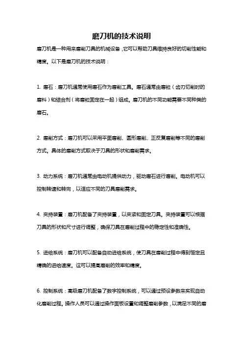
磨刀机的技术说明
磨刀机是一种用来磨削刀具的机械设备,它可以帮助刀具维持良好的切削性能和精度。
以下是磨刀机的技术说明:
1. 磨石:磨刀机通常使用磨石作为磨削工具。
磨石通常由磨粒(齿刃切削时的磨料)和结合剂(将磨粒固定在一起)组成。
磨刀机的不同功能需要不同种类的磨石。
2. 磨削方式:磨刀机可以采用平面磨削、圆形磨削、正反复磨削等不同的磨削方式。
具体的磨削方式取决于刀具的形状和磨削需求。
3. 动力系统:磨刀机通常由电动机提供动力,驱动磨石进行磨削。
电动机可以控制转速和转向,以适应不同的刀具磨削需求。
4. 夹持装置:磨刀机配备了夹持装置,以夹紧和固定刀具。
夹持装置可以根据刀具的形状和尺寸进行调整,确保刀具在磨削过程中的稳定性和准确性。
5. 进给系统:磨刀机可以配备自动进给系统,使刀具在磨削过程中得到恒定且精确的进给速度。
这可以提高磨削的效率和精度。
6. 控制系统:高级磨刀机配备了数字控制系统,可以通过预设参数来实现自动化磨削过程。
操作人员可以通过操作面板设置和调整磨削参数,以满足不同的磨
削需求。
总之,磨刀机是一项重要的工具,可以帮助刀具维持良好的切削性能和精度。
通过合适的磨石、磨削方式和夹持装置,以及完善的动力、进给和控制系统,磨刀机可以实现高效、高精度的刀具磨削。
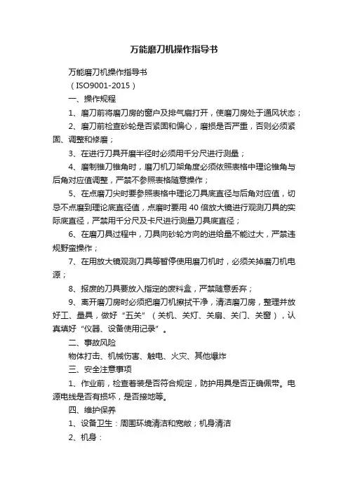
万能磨刀机操作指导书万能磨刀机操作指导书(ISO9001-2015)一、操作规程1、磨刀前将磨刀房的窗户及排气扇打开,使磨刀房处于通风状态;2、磨刀前检查砂轮是否紧固和偏心,磨损是否严重,否则必须紧固、调整和修磨;3、在进行刀具开磨半径时必须用千分尺进行测量;4、磨制锥刀锥角时,磨刀机刀架角度必须依照表格中理论锥角与后角对应值调整,严禁不参照表格随意操作;5、在点磨刀尖时要参照表格中理论刀具底直径与后角对应值,切忌不点磨到理论底直径值,点磨时要用40倍放大镜进行观测刀具的实际底直径,严禁用千分尺及卡尺进行测量刀具底直径;6、在磨刀具过程中,刀具向砂轮方向的进给量不能过大,严禁违规野蛮操作;7、在用放大镜观测刀具等暂停使用磨刀机时,必须关掉磨刀机电源;8、报废的刀具要放入指定的废料盒,严禁随意丢弃;9、离开磨刀房时必须把磨刀机擦拭干净,清洁磨刀房,整理并放好工、量具,做好“五关”(关机、关灯、关扇、关门、关窗),认真填好“仪器、设备使用记录”。
二、事故风险物体打击、机械伤害、触电、火灾、其他爆炸三、安全注意事项1、作业前,检查着装是否符合规定,防护用具是否正确佩带。
电源电线是否有损坏,是否接地等。
四、维护保养1、设备卫生:周围环境清洁和宽敞;机身清洁2、机身:砂轮片无裂纹、变形、破损;砂轮片螺母紧固,无松动或偏心;砂轮主轴进给调整、止动杆灵活可靠;砂轮修石笔良好紧固;刀架体固定安全,夹持直径范围在3-16mm;承轴微调、横向移动杆灵活、润滑;多角度手柄操作灵活、可靠。
3、电气:电源线绝缘胶皮完整,接地良好;360°照明良好,电源开关动作正常。
4、运转:电机、砂轮主轴运转正常,无异响。
..Model: U2万能磨刀机UNIVERSAL CUTTER /GRINDER操作手册OPERATING HANDBOOKVOLTAGE 220V / 50 HZ POWER REQ. 370 WSPINDLE R.P.M 5200 RPM MOTOR AMPS: 1.68 AMPS京雕精密机械JINGDIAO PRECISION MACHINERY CO,. LTD目录附件说明------------------------------------------------------------------------------------------------------------------------------------------1砂轮主轴------------------------------------------------------------------------------------------------------------------------------------------2分度头托架保养---------------------------------------------------------------------------------------------------------------------------------2修整砂轮------------------------------------------------------------------------------------------------------------------------------------------3刀具外形-刀具角度-切销速度----------------------------------------------------------------------------------------------------------------3刀具切销速度------------------------------------------------------------------------------------------------------------------------------------3用砂轮定刀刃中心------------------------------------------------------------------------------------------------------------------------------4斜切削刃刀具前角的外圆磨法---------------------------------------------------------------------------------------------------------------5端切削刃(直线)刀具前角的外圆磨法-------------------------------------------------------------------------------------------------------5 端切销刃(圆形)刀具前角的外圆磨法-------------------------------------------------------------------------------------------------------6 磨尖头刀具---------------------------------------------------------------------------------------------------------------------------------------7斜切削刃和端切削锥形刀具的外圆磨法---------------------------------------------------------------------------------------------------7斜切削刃和端切削刃圆锥形刀具的前角磨削---------------------------------------------------------------------------------------------8斜切削刃和端切削刃(圆形)锥形刀具的前角磨削----------------------------------------------------------------------------------------9附件------------------------------------------------------------------------------------------------------------------------------------------------9特殊附件------------------------------------------------------------------------------------------------------------------------------------------9钻头磨削说明--------------------------------------------------------------------------------------------------------12---------------------------10 端铣刀磨削说明--------------------------------------------------------------------------------------------------------------------------------11 车刀刀头磨削说明-----------------------------------------------------------------------------------------------------------------------------11 主机(零部件及装配示意图)-----------------------------------------------------------------------------------------------------------------12 旋转座附件(零部件及装配示意图)--------------------------------------------------------------------------------------------------------13 钻头磨削附件(零部件及装配示意图) -----------------------------------------------------------------------------------------------------13 车刀磨用附件(零部件及装配示意图) -----------------------------------------------------------------------------------------------------13 端铣刀磨用附件(零部件及装配示意图) --------------------------------------------------------------------------------------------------14 电器原理图--------------------------------------------------------------------------------------------------------------------------------------14附件说明砂轮主轴砂轮主轴的轴承在出厂时已调节好,同时排除了轴在转动过程中的间隙,在使用过程中,随着时间的迁移,间隙又会产生,这时可用上紧两个螺母M 来消除它。

数控单面磨刀机床使用说明————————————————————————————————作者:————————————————————————————————日期:数控单面磨刀机床使用维护说明书茂名怡华机械有限公司MAOMING YIHUA MACHINE CO。
,LTD。
目录一、机床的用途及特性概述—-—————-———--—-———--—-———----———-----——————-—--2二、技术规格—-——--——-———-——-—-——-——-———-——----——-—--—-————---————--————----—-2三、安全方面的注意事项—--——--—--—-—----—----—-——-----—-———--——-—---—----3四、机床操作—-————--——-—--—--—-—-—--—-—--—-———--———-——-——-—--—--—-—--——-—————4五、机床的润滑与保养--——-—-----——-—-----—-—-—---—-——————--———---—---———--5六、机床的电器维护—----——————-—--——-—-—--————-—--—-—————-—-----—-——--—-——-5七、编程方法说明及编程实例——-—--—-———--—-—-—-——-—-————-—-—-——---———-6八、电器原理图-—-————-———-——-——-----—----—--—--———----———-——---—-—-—-——---31一、机床的用途及特性概述1.用途:对各种剪刀内侧、刃口和各类刀具的平面、斜面以及各种金属及陶瓷制品的表面一次或多次磨削完成。
2.特性:1)选用GSK980TA1数控系统,性能稳定、能实现两轴、三轴联动,自动进给、自动补偿等功能。
2)机床下导轨进行表面高频淬火,导轨表面硬度高、上导轨贴塑,耐磨性能优越.三轴机采用滚珠直线导轨,摩擦系数小、精度高。
德信诚培训网
更多免费资料下载请进: 好好学习社区
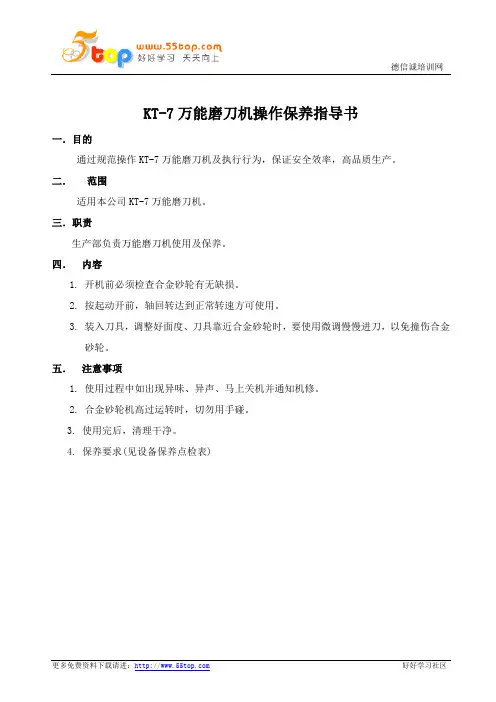
KT-7万能磨刀机操作保养指导书
一.目的
通过规范操作KT-7万能磨刀机及执行行为,保证安全效率,高品质生产。
二. 范围
适用本公司KT-7万能磨刀机。
三.职责
生产部负责万能磨刀机使用及保养。
四. 内容
1. 开机前必须检查合金砂轮有无缺损。
2. 按起动开前,轴回转达到正常转速方可使用。
3. 装入刀具,调整好面度、刀具靠近合金砂轮时,要使用微调慢慢进刀,以免撞伤合金
砂轮。
五. 注意事项
1. 使用过程中如出现异味、异声、马上关机并通知机修。
2. 合金砂轮机高过运转时,切勿用手碰。
3. 使用完后,清理干净。
4. 保养要求(见设备保养点检表)。

PRODUCT MANUAL- M161 MODEL 401 NSF ELECTRIC KNIFE SHARPENER-WITH SNAP IN KNIFE GUIDE(for serial #’s higher than 4155 built after may 2002)Please read thoroughly before operation and keep for future referenceModel 401 Knife Sharpener SpecificationsModel No.401Power Requirements115 volt, 1.5 Amps, 50 – 60 HZ230 volt, 0.5 Amps, 50 – 60 HZSpeed1550 RPMSize4” D x 4 ¾” H x 9 ¾” W(102mm x 121mm x 248mm)Weight8.9 lbs. (4.0 kg.)1. Knife Sharpener DescriptionThe Edlund Company Inc manufactures the Model 401 knife sharpener. It is approved by the appropriate certifying organizations. The knife sharpener uses a 3-inch diameter by one-inch wide grinding wheel to sharpen knives and other utensils. The sharpener consists of a grinding wheel, which is mounted on an arbor and attached to a drive motor. The motor is mounted to a stainless steel base using motor mounting plates. The sharpener is enclosed in a stainless steel housing with a plastic knife guide assembly secured to the base with the snap in guides. The unit isequipped with a rocker switch to turn the motor on or off and a safety interlock switch which will not allow the unit to operate if the plastic knife guide is not in place.2. Knife Sharpener OperationTo operate, plug the power cord into a grounded outlet with the same voltage as listed on the bottom of the knife sharpener base. Turn the unit on using the rocker switch and then use the following steps.1. Sanitize your hands and knife prior to sharpening.2. Hold knife against the outside edge of the left slot.Warning! Hold knife firmly so that it will not be pulled away bythe rotation of the grinding wheel.3. Pull the knife through in a horizontal motion keeping pressure onthe wheel light and even.4. Hold the knife against the outside edge of the right slot and pullthrough in a horizontal motion keeping pressure on the wheel lightand even.5. Repeat steps 2-4 until the desired edge is achieved.6. Sanitize knife and hands.Initial sharpening of knives may require several passes to createthe correct angle of the knife. Subsequent sharpening will onlyrequire a few passes to achieve a sharp, long lasting knife-edge.3. Cleaning InstructionsWarnings! Never clean or maintain knife sharpener without unplugging it from the electric source.Never submerge or place knife sharpener in water.Never blow out unit using and air gun- metal may blow inside of the motor and damage it.The knife sharpener must be cleaned after each use.Unplug the unit from the power source and remove theknife guide. To remove the knife guide press the twoplastic tabs (located underneath and towards the frontof the sharpener) towards each other and then lift theblue knife guide upwards (see figure on right). Gentlyshake out the accumulated grinding dust from theinside into a waste receptacle. Wipe the exterior andknife guide using a damp cloth.When the cleaning is complete insert the knife guideinto the knife sharpener cover and make sure that theplastic tabs snap back into place.Trouble Shooting GuideAn Edlund authorized service technician should do all repairs. Call the Factory or Authorized dealer for more information.4. INSTRUCTIONS FOR REPLACING GRIND WHEELThe grinding wheel is designed to last up to several years based on normal use (this may vary depending on use). The grinding wheel is fully worn out and needs replacing when the knife no longer makes contact with the wheel while positioned against the plastic knife guide. Areplacement wheel and arbor can be ordered from your local Edlund dealer as part number#A526S. To replace the grinding wheel, first unplug the unit from the power source. Remove the knife guide. Loosen the setscrew (use a 3/32” Allen wrench) until you are able to slide the wheel and arbor off of the motor shaft (FIGURE 1). Replace with the new wheel and arbor, the factory sets the stone and arbor with Shim (S291). This shim should be placed between the motor andthe wheel. The wheel should be placed flush against the shim and the setscrew tightened. Next remove the shim and the wheel will be set .120 inches away from the motorFIGURE 1. ATTACHING WHEELReplace the knife guide. The grinding wheel should be aligned after installation so that an equal portion of the wheel is visible in the left and right knife guide slots when the knife guide is in place (FIGURE 2). The knife sharpener is now ready for use.FIGURE 2. PROPERLY INSTALLED STONEPart ReferencePARTS LISTPART # QTY DESCRIPTIONA5261ASSEMBLY, #395/401 GRIND WHEELA5361ASSEMBLY, 401 SNAP IN KNIFE GUIDEA5371ASSEMBLY, #401 SNAP IN BASEA5381WELDMENT, #401 SNAP IN COVERB2971BUSHING,1/2"SNAP,3/8"IDC0731CLAMP, #201 CABLEC0921CONNECTOR, #390/395/CH-5000 LEADC0991CORD SET, REGULAR 7', 18/3, GRAYI0041INSULATOR, ECO MICRO SWITCH PADM0141MOTOR, 395/401 115V #7163-7783M0151MOTOR, 395/401 230VN0194NUT, 10-32 PLATED HEXN0201NUT, 10-32 S/S HEXP086F 1PLATE, 401 S/S MOTOR MTG. FRONTP086S 1PLATE, 401 S/S MOTOR MTG. BACKR0231WASHER, #8 S/S LOCKS0494SCREW, 10-32 X 3/8 S/S HEX HEADS0742SCREW, 4-40 X 5/8 BRASS RHMS0853SCREW, 8-32 X 1/4 S/S RHMS4031SWITCH, CH-350 USA LIGHTED ROCKERS4331 1SWITCH, 230VS5611SWITCH, 401 INTERLOCK MICROT0062TERMINAL, #203/266 FEMALE, 3/16T0071TERMINAL, ECO ROUND TONGUET054(3)(4)TERMINAL, 1/4" FEMALE FULLY INSW0108WASHER, #10 S/S FLATW0174WASHER, #10 EXT. TOOTH LOCK, PTDW0192WASHER, #4 INTRL TOOTH LOCK, S/SW0233WASHER, #8 S/S LOCKW1034WASHER, #10 S/S INTERNAL TOOTH LOCKW1051WASHER, 1/4" S/S FLAWarranties:The Edlund Company warrants these products to be free from defects in material and workmanship for a period of one year from date of purchase. The company’s obligation under this warranty is limited to repairing or replacing without charge any parts or parts found to be defective under normal use. It is the responsibility of the purchaser to return the entire unit to the factory or a factory service branch, transportation charges prepaid. This warranty does no cover parts that must be replaced under normal use, including knives and drive gears on can openers. The company authorizes no other warranty, written or verbal. Carrier is responsible for merchandise in transit to you.。
磨刀机使用手册介绍本文档提供了磨刀机的详细使用说明,包括操作步骤、注意事项和维护保养方法。
请在使用磨刀机前仔细阅读本手册。
操作步骤步骤一:准备1. 将磨刀机放置在平稳的台面上。
2. 插上电源并确保电源开关处于关闭状态。
步骤二:安装刀具1. 将需要磨刀的刀具安装在磨刀机上。
2. 使用提供的工具,紧固刀具以确保固定牢靠。
3. 确保刀具与磨刀机的接触面无杂质。
步骤三:调整磨刀机1. 打开磨刀机的操作面板。
2. 根据刀具类型和需要的刀口角度,选择适当的磨刀模式。
3. 使用调节钮设置所需的刀口角度和磨削深度。
步骤四:开始磨刀1. 打开电源开关,磨刀机启动。
2. 调节进给速度,确保与刀具类型相匹配。
3. 将刀具轻轻推入磨刀机,确保刀具与磨石接触。
4. 保持稳定的压力和均匀的推进速度,沿着刀具的切削边缘来回移动刀具,直到得到理想的刀口效果。
步骤五:结束磨刀1. 关闭电源开关,磨刀机停止运行。
2. 等待磨刀机完全停止后,取下已磨好的刀具。
3. 用清洁布清除磨削产生的杂质和金属屑。
注意事项1. 在使用磨刀机时,请戴上适合的防护手套和护目镜,保护好自己的安全。
2. 遵循磨刀机的使用规程和安全操作指南。
3. 不要让磨刀机过热,避免长时间连续使用,应适当停顿以使机器冷却。
4. 注意刀具的磨损程度,及时更换损坏的刀具,以免影响磨刀效果和安全性。
维护保养1. 定期清洁磨刀机的外部和内部,避免积尘和杂质影响机器性能。
2. 检查电源线是否有磨损或损坏,如有问题请及时更换。
3. 注意定期润滑磨刀机的关键部位,以保证正常运行。
4. 对于长时间未使用的磨刀机,应将其存放在干燥、通风的地方,避免受潮和腐蚀。
以上为磨刀机使用手册的内容,请根据本手册的指导进行正确的操作和维护保养。
如有问题,请咨询专业人士。
Model: U2万能磨刀机UNIVERSAL CUTTER /GRINDER操作手册OPERATING HANDBOOKVOLTAGE 220V / 50 HZ POWER REQ. 370 WSPINDLE R.P.M 5200 RPM MOTOR AMPS: 1.68 AMPS京雕精密机械JINGDIAO PRECISION MACHINERY CO,. LTD目录附件说明------------------------------------------------------------------------------------------------------------------------------------------1砂轮主轴------------------------------------------------------------------------------------------------------------------------------------------2分度头托架保养---------------------------------------------------------------------------------------------------------------------------------2修整砂轮------------------------------------------------------------------------------------------------------------------------------------------3刀具外形-刀具角度-切销速度----------------------------------------------------------------------------------------------------------------3刀具切销速度------------------------------------------------------------------------------------------------------------------------------------3用砂轮定刀刃中心------------------------------------------------------------------------------------------------------------------------------4斜切削刃刀具前角的外圆磨法---------------------------------------------------------------------------------------------------------------5端切削刃(直线)刀具前角的外圆磨法-------------------------------------------------------------------------------------------------------5端切销刃(圆形)刀具前角的外圆磨法-------------------------------------------------------------------------------------------------------6磨尖头刀具---------------------------------------------------------------------------------------------------------------------------------------7斜切削刃和端切削锥形刀具的外圆磨法---------------------------------------------------------------------------------------------------7斜切削刃和端切削刃圆锥形刀具的前角磨削---------------------------------------------------------------------------------------------8斜切削刃和端切削刃(圆形)锥形刀具的前角磨削----------------------------------------------------------------------------------------9附件------------------------------------------------------------------------------------------------------------------------------------------------9特殊附件------------------------------------------------------------------------------------------------------------------------------------------9钻头磨削说明-----------------------------------------------------------------------------------------------------------------------------------10端铣刀磨削说明--------------------------------------------------------------------------------------------------------------------------------11车刀刀头磨削说明-----------------------------------------------------------------------------------------------------------------------------11主机(零部件及装配示意图) -----------------------------------------------------------------------------------------------------------------12旋转座附件(零部件及装配示意图) --------------------------------------------------------------------------------------------------------13钻头磨削附件(零部件及装配示意图) -----------------------------------------------------------------------------------------------------13车刀磨用附件(零部件及装配示意图) -----------------------------------------------------------------------------------------------------13端铣刀磨用附件(零部件及装配示意图) --------------------------------------------------------------------------------------------------14电器原理图--------------------------------------------------------------------------------------------------------------------------------------14砂轮主轴砂轮主轴的轴承在出厂时已调节好,同时排除了轴在转动过程中的间隙,在使用过程中,随着时间的迁移,间隙又会产生,这时可用上紧两个螺母M来消除它。
广晟德电动磨刀机
使用说明书
一:电压:交流220V 功率:2X550w 频率:50Hz 二:使用方法:
1、合金刀安装:将(6)逆时针方向拧开:将(4)
取开,把待磨合金刀片装上去(刀口斜面向外);
将(4)及(6)装上拧紧。
2、磨刀钻石碗安装;将(2)放松,顺时针拧动(1)
将传动马达调离使金刀片较远距离;拧松及取下(5)、(3)、将钻石碗装上去(碗口向刀片方向),装上(3)拧紧(5)。
3、角度调整:逆时针缓慢拧(1),将传动马达推
向前,置钻石碗与合金刀片较近的地方:轻轻摆动马达,使钻石碗切口与合金刀斜面口平行一至,拧紧(2)。
4、磨刀:接通电源,缓慢拧动(1)(逆时针方向)
当开始听到钻石碗与合金刀断续相磨发出响声时,则停止拧动(1);等待几分钟,没再发出相磨响声(或较轻微响声)时,再逆时针缓调(1),至有比较长的相磨响声时,再停止拧动(1)。
重复以上动作2至3次(时间长短及重复次数视待磨刀片的缺损程度而定),一般到开始发出较完整的相磨声的当次为结束次数,或停机观察刀口锋圆度判断是否已磨好。
5、取刀:切断电源,顺时针拧动(1)将传动马达调离
合金刀较远位置,(拧松)及取下(4)小心将磨好的刀片拿出放好,向各机械部件注、擦防锈、润滑油,做好防尘、防潮工作,可延长机器的使用寿命。
注:磨刀时请勿用力突然向前拧动磨刀传动马
达或反复磨已磨好的刀片,以免过量损耗钻石
碗及刀片。
附图在下面。
Operating Instructions and Parts ManualDual-Sided 16ga. Box and Pan Brake Model PBF-1650DJET427 New Sanford RoadLaVergne, Tennessee 37086 Part No. M-752130 Ph.: 800-274-6848 Edition 2 08/2018 Copyright © 2016 JET1.0 IMPORTANT SAFETYINSTRUCTIONSREAD ALL INSTRUCTIONS BEFORE USING THIS MACHINE.WARNING – To reduce the risk of injury:1. Read and understand the entire owner'smanual before attempting assembly or operation.2. Read and understand the warnings posted onthe machine and in this manual. Failure tocomply with all of these warnings may causeserious injury.3. Replace the warning labels if they becomeobscured or removed.4. This box and pan brake is designed andintended for use by properly trained and experienced personnel only. If you are notfamiliar with the proper and safe operation of abrake, do not use until proper training andknowledge have been obtained.5. Do not use this brake for other than its intendeduse. If used for other purposes, JET disclaimsany real or implied warranty and holds itselfharmless from any injury that may result fromthat use.6. Always wear ANSI Z87.1 approved safetyglasses or face shield while using this brake.(Everyday eyeglasses only have impact resistant lenses; they are not safety glasses.) 7. Before operating this machine, remove tie,rings, watches and other jewelry, and rollsleeves up past the elbows. Do not wear looseclothing. Confine long hair. Non-slip footwear oranti-skid floor strips are recommended.8. Wear ear protectors (plugs or muffs) if noisereaches unsafe levels.9. Do not operate this machine while tired or underthe influence of drugs, alcohol or any medication.10. Remove adjusting keys and wrenches. Form ahabit of checking to see that keys and adjustingwrenches are removed from the machine before turning it on.11. Keep safety guards in place at all times whenthe machine is in use. If removed for maintenance purposes, use extreme cautionand replace the guards immediately after completion of maintenance. 12. Check damaged parts. Before further use of themachine, a guard or other part that is damagedshould be carefully checked to determine that itwill operate properly and perform its intendedfunction. Check for alignment of moving parts,binding of moving parts, breakage of parts, mounting and any other conditions that mayaffect its operation. A guard or other part that isdamaged should be properly repaired or replaced.13. Provide for adequate space surrounding workarea and non-glare, overhead lighting.14. Keep the floor around the machine clean andfree of scrap material, oil and grease.15. Keep visitors a safe distance from the workarea. Keep children away.16. Make your workshop child proof with padlocks,master switches or by removing starter keys. 17. Give your work undivided attention. Lookingaround, carrying on a conversation and “horse-play” are careless acts that can result in seriousinjury.18. Maintain a balanced stance at all times so thatyou do not fall into the blade or other movingparts. Do not overreach or use excessive forceto perform any machine operation.19. Use recommended accessories; improperaccessories may be hazardous.20. Maintain tools with care. Keep blades sharp andclean for the best and safest performance.Follow instructions for lubricating and changingaccessories.21. Do not stand on the machine. Serious injurycould occur if the machine tips over.22. Remove loose items and unnecessary workpieces from the area before operating the machine.23. Do not use in dangerous environment. Do notuse machine in damp or wet location, or exposeto rain. Keep work area well lighted.24. Sheet metal stock has sharp edges; use cautionwhen handling to prevent cuts.25. Keep hands clear of bending area whileoperating.26. Do not exceed rated capacity of brake.27. The brake should be secured to floor withappropriate fasteners.Familiarize yourself with the following safety notices used in this manual:This means that if precautions arenot heeded, it may result in minor injury and/or possible machine damage.This means that if precautions arenot heeded, it may result in serious, or possibly even fatal, injury.SAVE THESE INSTRUCTIONS2.0 About this manualThis manual is provided by JET, covering the safe operation and maintenance procedures for a JET Model BPF-1650D Dual-Sided Box and Pan Brake. This manual contains instructions on installation, safety precautions, general operating procedures, maintenance instructions and parts breakdown. Your machine has been designed and constructed to provide consistent, long-term operation if used in accordance with the instructions as set forth in this document.This manual is not intended to be a guide to sheet metal bending, bend allowances, material choice, etc. Consult a machinery’s handbook and/or experienced users for such information. Whatever accepted methods or materials are used, always make personal safety a priority.If there are questions or comments, please contact your local supplier or JET. JET can also be reached at our web site: .Retain this manual for future reference. If the machine transfers ownership, the manual should accompany it. Read and understand the entire contents of this manual before attempting assembly oroperation! Failure to comply may cause serious injury!Register your product online - /us/en/service-and-support/warranty/registration/WARNING: This product can expose you to chemicals including lead which is known to the State of California to cause cancer and birth defects or other reproductive harm. For more information go to http://www.p65warnings.ca. gov.WARNING: Some dust, fumes and gases created by power sanding, sawing, grinding, drilling, welding and other construction activities contain chemicals known to the State of California to cause cancer and birth defects or other reproductive harm. Some examples of these chemicals are:• lead from lead based paint• crystalline silica from bricks, cement and other masonry products• arsenic and chromium from chemically treated lumberYour risk of exposure varies, depending on how often you do this type of work. To reduce your exposure to these chemicals, work in a well-ventilated area and work with approved safety equipment, such as dust masks that are specifically designed to filter out microscopic particles. For more information go to / and http:// /wood.3.0 Table of contentsSection Page1.0 IMPORTANT SAFETY INSTRUCTIONS (2)2.0 About this manual (3)3.0 Table of contents (4)4.0 Specifications for 16x50 Box and Pan Brake (5)4.1 Floor Diagram (5)5.0 Features and terminology (6)6.0 Setup and assembly (7)6.1 Unpacking and cleanup (7)6.2 Contents of shipping container (7)6.3 Tools required for assembly (7)6.4 Assembly (7)7.0 Operation (7)7.1 Finger spacing (7)7.2 Adjusting setback (7)7.3 Adjusting clamping pressure (8)7.4 Repeat bends (8)7.5 General procedure (8)8.0 User-maintenance (8)8.1 Lubrication (8)8.2 Additional servicing (8)9.0 Troubleshooting PBF-1650D Box and Pan Brake (8)10.0 Replacement Parts (8)10.1.1 BPF-1650D Box and Pan Brake – Exploded View (9)10.1.2 PBF-1650D Box and Pan Brake – Parts List (10)11.0 Warranty and service (12)4.0 Specifications for 16x50 Box and Pan BrakeModel Number ...................................................................................................................................... PBF-1650D Stock Number (752130)Materials:Frame .......................................................................................................................... welded steel plate/tubing Clamping fingers .............................................................................................................................. ground steel Clamping block ................................................................................................................. p recision ground steel Capacities:Bending length .......................................................................................................................... 50 in. (1270 mm) Maximum thickness, mild steel ................................................................................................... 16 ga. (1.5 mm) Bending angle .................................................................................................................................. 0 – 135 deg. Maximum beam lift ................................................................................................................ 1-13/16 in. (46 mm) Maximum box depth ................................................................................................................. 2.5 in. (63.5 mm) Minimum flange in capacity material ............................................................................................. 0.4 in. (10mm) Nose angle (upper fingers) ...................................................................................................................... 42 deg. Nose radius ............................................................................................................................. 1/32 in. (0.79 mm) Number of fingers ............................................................................................................ ......12 upper, 12 lower Finger widths ........................................................... 1, 1-1/8, 1-3/8, 1-1/2, 1-3/4, 2, 3, 4, 6, 7-3/4, 10, 10-5/8 in. Weights:Net ............................................................................................................................................... 772 lb (350 kg) Shipping ....................................................................................................................................... 849 lb (385 kg) Dimensions:Height, floor to working surface ............................................................................................ 35-1/2 in. (902 mm) Shipping (LxWxH) .......................................................................... 67-3/8 x 28 x 51-1/2 in. (171 x 71 x 131 cm) Assembled (LxWxH) ................................................................................... 63 x 38 x 45 in. (160 x 97 x 114 cm) The specifications in this manual were current at time of publication, but because of our policy of continuous improvement, JET reserves the right to change specifications at any time and without prior notice, without incurring obligations.L=length, W=width, H=height4.1 Floor DiagramFigure 15.0 Features and terminologyFigure 21. Clamping leaf2. Clamping fingers3. Clamping adjustment nut (x2)4. Stop bolt5. Setback locking screw (x2)6. Setback knob (x2)7. Bending leaf fingers8. Bending leaf9. Foot pedal for clamping 10. Foot pedal lock11. Leg extension (x2)12. Crown adjustment rod13. Air spring14. Grease fitting (x2)15. Stop collar16. Stop collar screw17. Eccentric disc6.0 Setup and assemblyRead and understand all assembly instructions before attempting assembly. Failure to comply may cause serious injury.6.1 Unpacking and cleanupInspect contents of shipping container for shipping damage. Report any damage to your distributor. Remove all contents from carton, and compare to the contents list in this manual. Report any part shortages to your distributor.Do not discard carton or packing material until machine is assembled and working properly. Exposed metal areas may have a rust protectant applied. Remove this with a soft rag and solvent such as kerosene. (Do not use gasoline, paint thinner, acetone, etc., as these will damage painted surfaces.)6.2 Contents of shipping container1 Box and Pan Brake2 Support legs with screws1 Instructions and Parts Manual (not shown)1 Warranty Card (not shown)6.3 Tools required for assembly8mm hex key6.4 AssemblyNumbers in parentheses refer to items in Figure 2. 1. Remove any straps or screws securing thebrake, and raise machine using properly ratedlifting equipment. See Figure 3 for lifting strapplacement.Figure 3Continue to stabilize machine while installing support legs. 2. Attach the two leg extensions (11) with theprovided socket head screws and flat washers. 3. Secure brake to floor using lag screws or similarsystem. See diagram, Figure 1. Also level thebrake; use shims if needed.4. The stop collar screw (16) has been tightenedfor shipping purposes. This screw must beloosened to allow clamping machine adjustments.7.0 OperationNumbers in parentheses refer to items in Figure 2. 7.1 Finger spacingUpper (2) and lower (7) fingers are mounted on T-nuts that slide within the underlying channel. Remove fingers by removing the screw(s); or reposition fingers at any place along the beam by loosening screw and sliding the T-nuts. Firmly tighten screws on fingers before operating.7.2 Adjusting setbackThe bending leaf lower fingers (7) must be adjusted for proper clearance or “setback” (A, Figure 3) based on material thickness (B, Figure 3). Generally, setback for material within four gauges of capacity should be twice the thickness of material. For lighter gauges, use 1-1/2 times the material thickness. Consult a machinery handbook for bend allowances.Figure 31. Loosen setback locking screws (5).2. Rotate setback knobs (6) in equal amounts(clockwise decreases distance). Refer to adjoining scale, marked with 0.002-inch graduations.Note: When increasing distance (counter-clockwise), you may have to pull back slightlyon the bending leaf to take up any backlash.3. Bring clamping leaf into position and checksetback.4. Repeat above steps until proper distance isachieved.5. Tighten locking screws (5).If a crown develops in the material, this can be adjusted out by loosening or tightening the hex nuts on the crown adjustment rod (12). Note: This rod has been correctly set by the manufacturer and should only be adjusted when needed.7.3 Adjusting clamping pressure Clamping pressure may vary depending upon material gauge. Pressure should be great enough to hold material securely, but not so much that it becomes difficult to clamp.Rotate clamping adjustment nuts (3) equally to set clamping pressure. Proper adjustment will allow foot pedal (9) to be locked (10).7.4 Repeat bendsLoosen stop collar screw (16) and adjust stop bolt (4) to limit swing of bending leaf. Retighten screw (16).7.5 General procedure1. Adjust upper and/or lower fingers for width ofmaterial and type of bend.2. Adjust for setback and clamping pressure.3. Position stop bolt if needed.4. Align material in machine and press foot pedaluntil it locks.5. Raise bending leaf to desired angle.6. Lower bending leaf and press foot pedal lock torelease material.8.0 User-maintenance Periodically wipe down machine with a soft rag. Keep upper and lower fingers clean and clear of debris. Apply light coat of SAE30 oil to upper and lower fingers.Periodically check tightness of fasteners.8.1 LubricationDaily insert a multi-purpose grease into the two fittings (14).Lightly apply grease to pivot points around machine, such as setback rods and eccentric disc.Apply light coat of SAE30 oil to all machined (unpainted) parts when not in use, to inhibit rust. 8.2 Additional servicingAny additional servicing should be performed by an authorized service technician.9.0 Troubleshooting PBF-1650D Box and Pan Brake Symptom PossibleCause CorrectionBends created with great difficulty.Machine capacity exceeded. Use material within capacity. Incorrect setback. Increase setback.Clamping leaf will not clamp properly.Improper adjustment.Decrease distance between fingers andbeam.Clamping not even across width. Rotate adjustment nuts equal amount.Bend radius not consistent across material.Machine capacity exceeded. Use material within capacity.Bending leaf edge not parallel to fingers. Adjust bending leaf equally on both ends. Bending leaf has crown. Correct with crown adjustment rod.10.0 Replacement PartsReplacement parts are listed on the following pages. To order parts or reach our service department, call 1-800-274-6848 Monday through Friday, 8:00 a.m. to 5:00 p.m. CST. Having the Model Number and Serial Number of your machine available when you call will allow us to serve you quickly and accurately.Non-proprietary parts, such as fasteners, can be found at local hardware stores, or may be ordered from JET. Some parts are shown for reference only, and may not be available individually.10.1.1 BPF-1650D Box and Pan Brake – Exploded View10.1.2 PBF-1650D Box and Pan Brake – Parts ListIndex No Part No Description Size Qty1 ................ H40-210 .................... Adjusting Nut ........................................................... .. (2)2 ................ PBF1650D-02 ........... Clamping Leaf. ........................................................ .. (1)3 ................ PBF1650D-03 ........... T-Nut ........................................................................ (48)4-1 ............. PBF1650D-04-1 ........ Upper Finger ............................................................ 1” .. (1)4-2 ............. PBF1650D-04-2 ........ Upper Finger ............................................................ 1-1/8” . (1)4-3 ............. PBF1650D-04-3 ........ Upper Finger ............................................................ 1-3/8” . (1)4-4 ............. PBF1650D-04-4 ........ Upper Finger ............................................................ 1-1/2” . (1)4-5 ............. PBF1650D-04-5 ........ Upper Finger ............................................................ 1-3/4” . (1)4-6 ............. PBF1650D-04-6 ........ Upper Finger ............................................................ 2” .. (1)4-7 ............. PBF1650D-04-7 ........ Upper Finger ............................................................ 3” .. (1)4-8 ............. PBF1650D-04-8 ........ Upper Finger ............................................................ 4” .. (1)4-9 ............. PBF1650D-04-9 ........ Upper Finger ............................................................ 6” .. (1)4-10 ........... PBF1650D-04-10 ...... Upper Finger ............................................................ 7-3/4” . (1)4-11 ........... PBF1650D-04-11 ...... Upper Finger ............................................................ 10” (1)4-12 ........... PBF1650D-04-12 ...... Upper Finger ............................................................ 10-5/8” .. (1)5 ................ TS-1505021 .............. Socket Head Cap Screw ......................................... M10x20 .. (66)6 ................ PBF1650D-06 ........... Clamping Block ........................................................ .. (1)7 ................ PBF1650D-07 ........... Adjusting Nut Spring ................................................ .. (2)8 ................ TS-155011 ................ Flat Washer ............................................................. 20mm . (6)9 ................ PBF1650D-09 ........... Grease Fitting .......................................................... M8x1 .. (2)10 .............. H40-227 .................... Bushing .................................................................... .. (2)11 .............. H40-226 .................... Flat Washer ............................................................. 30 . (2)12 .............. H40-209 .................... Bending Leaf Pin ..................................................... .. (1)13 .............. TS-1505051 .............. Socket Head Cap Screw ......................................... M10x35 . (1)14 .............. H40-204 .................... Stop Collar ............................................................... .. (1)15 .............. TS-1540071 .............. Hex Nut .................................................................... M10 . (1)16 .............. TS-1505061 .............. Socket Head Cap Screw ......................................... M10x40 . (1)17 .............. PBF1650D-17 ........... Leg ........................................................................... .. (2)18 .............. BPF1240-18 .............. Ext. Retaining Ring .................................................. 25mm .. (13)19 .............. H40-208 .................... Leg Pin .................................................................... .. (3)20 .............. TS-1505041 .............. Socket Head Cap Screw ......................................... M10x30 . (4)21 .............. H40-217-3G .............. Extension Bracket .................................................... .. (2)22 .............. PBF1650D-22 ........... Disc Spring .............................................................. Ø40xø20x1mm . (4)23 .............. H40-205 .................... Rod .......................................................................... .. (2)24 .............. H40-206 .................... Foot Pedal Lever ..................................................... .. (4)25 .............. H40-207.................... Lever Pin .................................................................. .. (4)26 .............. PBF1650D-26 ........... Foot Pedal ............................................................... .. (1)27 .............. H40-402 .................... Tread Plate Rubber ................................................. .. (1)28 .............. H40-211 .................... Roll Pin .................................................................... .. (1)29 .............. BPF1240-29 .............. Ext. Retaining Ring .................................................. 10mm . (2)30 .............. H40-213.................... Foot Pedal Lock ....................................................... .. (1)31 .............. BPF1240-31 .............. Spring Pin ................................................................ 8x50mm (1)32 .............. TS-1550061 .............. Flat Washer ............................................................. 8mm (1)33 .............. H40-212 .................... Pedal Lock Spring ................................................... .. (1)34-1 ........... PBF1650D-34-1 ........ Lower Finger ............................................................ 1” .. (1)34-2 ........... PBF1650D-34-2 ........ Lower Finger ............................................................ 1-1/8” . (1)34-3 ........... PBF1650D-34-3 ........ Lower Finger ............................................................ 1-3/8” . (1)34-4 ........... PBF1650D-34-4 ........ Lower Finger ............................................................ 1-1/2” . (1)34-5 ........... PBF1650D-34-5 ........ Lower Finger ............................................................ 1-3/4” . (1)34-6 ........... PBF1650D-34-6 ........ Lower Finger ............................................................ 2” .. (1)34-7 ........... PBF1650D-34-7 ........ Lower Finger ............................................................ 3” .. (1)34-8 ........... PBF1650D-34-8 ........ Lower Finger ............................................................ 4” .. (1)34-9 ........... PBF1650D-34-9 ........ Lower Finger ............................................................ 6” .. (1)34-10 ......... PBF1650D-34-10 ...... Lower Finger ............................................................ 7-3/4” . (1)34-11 ......... PBF1650D-34-11 ...... Lower Finger ............................................................ 10” (1)34-12 ......... PBF1650D-34-12 ...... Lower Finger ............................................................ 10-5/8” .. (1)35 .............. BPF1240-31 .............. Spring Pin ................................................................ 8x50mm (2)37 .............. PBF1650D-37 ........... O-Ring ..................................................................... 25x3.55mm . (2)38 .............. PBF1650D-38 ........... Setback Rod ............................................................ .. (2)Index No Part No Description Size Qty39 .............. PBF1650D-39 ........... Setback Knob .......................................................... .. (2)40 .............. PBF1650D-40 ........... Operating Handle .................................................... .. (2)41 .............. PBF1650D-41 ........... Adjusting Rod .......................................................... .. (1)42 .............. PBF1650D-42 ........... Bending Leaf ........................................................... .. (1)43 .............. TS-1550111 .............. Flat Washer ............................................................. 20 . (2)44 .............. TS-2310201 .............. Hex Nut .................................................................... M20 . (2)45 .............. TS-2228161 .............. Hex Cap Screw ........................................................ M8x16 (2)46 .............. PBF1650D-46 ........... Fixing Plate .............................................................. .. (1)47 .............. PBF1650D-47 ........... Air Spring ................................................................. .. (1)48 .............. TS-2211451 .............. Hex Cap Screw ........................................................ M12x45 . (2)49 .............. TS-2311121 .............. Hex Nut .................................................................... M12 . (2)50 .............. PBF1650D-50 ........... Eccentric Holder ...................................................... .. (1)51 .............. TS-155011 ................ Flat Washer ............................................................. M20 . (2)52 .............. TS-1502021 .............. Socket Head Cap Screw ......................................... M5x10 (2)53 .............. PBF1650D-53 ........... Rubber Pad ............................................................. .. (2)54 .............. PBF1650D-54 ........... Bushing .................................................................... .. (4)55 .............. TS-1521031 .............. Socket Set Screw .................................................... M4x8 .. (2)56 .............. PBF1650D-56 ........... Scale ........................................................................ .. (2).................. LM000240 ................. ID/Warning Label, PBF-1650D (not shown) ............ .. (1).................. JET-165 ..................... JET Logo (not shown) ............................................. 165x68mm .. (1)11.0 Warranty and serviceJET warrants every product it sells against manufacturers’ defects. If one of our tools needs service or repair, please contact Technical Service by calling 1-800-274-6846, 8AM to 5PM CST, Monday through Friday.Warranty PeriodThe general warranty lasts for the time period specified in the literature included with your product or on the official JET branded website.•JET products carry a limited warranty which varies in duration based upon the product. (See chart below) •Accessories carry a limited warranty of one year from the date of receipt.•Consumable items are defined as expendable parts or accessories expected to become inoperable within a reasonable amount of use and are covered by a 90 day limited warranty against manufacturer’s defects. Who is CoveredThis warranty covers only the initial purchaser of the product from the date of delivery.What is CoveredThis warranty covers any defects in workmanship or materials subject to the limitations stated below. This warranty does not cover failures due directly or indirectly to misuse, abuse, negligence or accidents, normal wear-and-tear, improper repair, alterations or lack of maintenance. JET woodworking machinery is designed to be used with Wood. Use of these machines in the processing of metal, plastics, or other materials outside recommended guidelines may void the warranty. The exceptions are acrylics and other natural items that are made specifically for wood turning. Warranty LimitationsWoodworking products with a Five Year Warranty that are used for commercial or industrial purposes default to a Two Year Warranty. Please contact Technical Service at 1-800-274-6846 for further clarification.How to Get Technical SupportPlease contact Technical Service by calling 1-800-274-6846. Please note that you will be asked to provide proof of initial purchase when calling. If a product requires further inspection, the Technical Service representative will explain and assist with any additional action needed.JET has Authorized Service Centers located throughout the United States. For the name of an Authorized Service Center in your area call 1-800-274-6846 or use the Service Center Locator on the JET website.More InformationJET is constantly adding new products. For complete, up-to-date product information, check with your local distributor or visit the JET website.How State Law AppliesThis warranty gives you specific legal rights, subject to applicable state law.Limitations on This WarrantyJET LIMITS ALL IMPLIED WARRANTIES TO THE PERIOD OF THE LIMITED WARRANTY FOR EACH PRODUCT. EXCEPT AS STATED HEREIN, ANY IMPLIED WARRANTIES OF MERCHANTABILITY AND FITNESS FOR A PARTICULAR PURPOSE ARE EXCLUDED. SOME STATES DO NOT ALLOW LIMITATIONS ON HOW LONG AN IMPLIED WARRANTY LASTS, SO THE ABOVE LIMITATION MAY NOT APPLY TO YOU.JET SHALL IN NO EVENT BE LIABLE FOR DEATH, INJURIES TO PERSONS OR PROPERTY, OR FOR INCIDENTAL, CONTINGENT, SPECIAL, OR CONSEQUENTIAL DAMAGES ARISING FROM THE USE OF OUR PRODUCTS. SOME STATES DO NOT ALLOW THE EXCLUSION OR LIMITATION OF INCIDENTAL OR CONSEQUENTIAL DAMAGES, SO THE ABOVE LIMITATION OR EXCLUSION MAY NOT APPLY TO YOU.JET sells through distributors only. The specifications listed in JET printed materials and on official JET website are given as general information and are not binding. JET reserves the right to effect at any time, without prior notice, those alterations to parts, fittings, and accessory equipment which they may deem necessary for any reason whatsoever. JET® branded products are not sold in Canada by JPW Industries, Inc.Product Listing with Warranty Period90 Days – Parts; Consumable items1 Year – Motors; Machine Accessories2 Year – Metalworking Machinery; Electric Hoists, Electric Hoist Accessories; Woodworking Machinery usedfor industrial or commercial purposes5 Year – Woodworking MachineryLimited Lifetime – JET Parallel clamps; VOLT Series Electric Hoists; Manual Hoists; Manual HoistAccessories; Shop Tools; Warehouse & Dock products; Hand Tools; Air ToolsNOTE: JET is a division of JPW Industries, Inc. References in this document to JET also apply to JPW Industries, Inc., or any of its successors in interest to the JET brand.。
Model: U2万能磨刀机UNIVERSAL CUTTER /GRINDER操作手册OPERATING HANDBOOKVOLTAGE 220V / 50 HZ POWER REQ. 370 WSPINDLE 5200 RPM MOTOR AMPS: AMPS京雕精密机械JINGDIAO PRECISION MACHINERY CO,. LTD目录附件说明------------------------------------------------------------------------------------------------------------------------------------------1砂轮主轴------------------------------------------------------------------------------------------------------------------------------------------2分度头托架保养---------------------------------------------------------------------------------------------------------------------------------2修整砂轮------------------------------------------------------------------------------------------------------------------------------------------3刀具外形-刀具角度-切销速度----------------------------------------------------------------------------------------------------------------3刀具切销速度------------------------------------------------------------------------------------------------------------------------------------3用砂轮定刀刃中心------------------------------------------------------------------------------------------------------------------------------4斜切削刃刀具前角的外圆磨法---------------------------------------------------------------------------------------------------------------5端切削刃(直线)刀具前角的外圆磨法-------------------------------------------------------------------------------------------------------5端切销刃(圆形)刀具前角的外圆磨法-------------------------------------------------------------------------------------------------------6磨尖头刀具---------------------------------------------------------------------------------------------------------------------------------------7斜切削刃和端切削锥形刀具的外圆磨法---------------------------------------------------------------------------------------------------7斜切削刃和端切削刃圆锥形刀具的前角磨削---------------------------------------------------------------------------------------------8斜切削刃和端切削刃(圆形)锥形刀具的前角磨削----------------------------------------------------------------------------------------9附件------------------------------------------------------------------------------------------------------------------------------------------------9特殊附件------------------------------------------------------------------------------------------------------------------------------------------9钻头磨削说明-----------------------------------------------------------------------------------------------------------------------------------10端铣刀磨削说明--------------------------------------------------------------------------------------------------------------------------------11车刀刀头磨削说明-----------------------------------------------------------------------------------------------------------------------------11主机(零部件及装配示意图) -----------------------------------------------------------------------------------------------------------------12旋转座附件(零部件及装配示意图) --------------------------------------------------------------------------------------------------------13钻头磨削附件(零部件及装配示意图) -----------------------------------------------------------------------------------------------------13车刀磨用附件(零部件及装配示意图) -----------------------------------------------------------------------------------------------------13端铣刀磨用附件(零部件及装配示意图) --------------------------------------------------------------------------------------------------14电器原理图--------------------------------------------------------------------------------------------------------------------------------------14附件说明砂轮主轴砂轮主轴的轴承在出厂时已调节好,同时排除了轴在转动过程中的间隙,在使用过程中,随着时间的迁移,间隙又会产生,这时可用上紧两个螺母M来消除它。
为达此目的,在松开螺钉S后,可从座中拉出砂轮主轴,同时拆下各零部件,如下图所示,在对轴进行重新装配时,要细心地把螺栓S拧入腔中,以便使轴的各组件保持在固定的位置上。
分度头托架保养在使用一个大周期之后,需要拆卸分度头托架并对弹簧套筒轴承分度头滑板和旋转臂等进行清洗和润滑。
弹簧套筒轴承为拆开弹性套筒,按如下进行:拧下环形螺母N5,分度盘N4和分度环R7,按顺序再拧下两个螺母M3,拉出分度头轴承套筒E,纵向滑板L上的环形滑脂室及其能够到达的地主,都要用汽油进行清洗并生新装满润滑脂。
滑板松开夹紧螺栓T5且卸下螺钉S5,拉出分度头滑板S,清洗其全部工作表面,轻轻地抹上油,横向滑板Q拆不下来。
松开夹紧螺栓T1并拧动螺栓S4以移动横向滑板达到它的极限位置,清洗其支承表面并轻轻地抹上油。
旋转臂为拆下旋转臂和分度头,作为一个组件,卸下两个螺母M4,清洗支承表面并给它们抹上油。
调整分度盘F的夹紧机构如果在使用一个大周期之后,夹坚紧手柄T6已锁不住分度盘F,螺栓U2就必须进行调整。
为此,按如下步骤进行,向上面已说过的卸下旋转臂;拆下螺栓U3和止动板A1;底座螺母M2和螺钉U1并拉出夹紧手柄T6,抬起分度盘F,抽出调整螺母和螺栓U2并将螺栓相对螺母转动180o减少其长度,重新装配各组件时,按上述相反程序进行。
校准转动90o用的止动销由于使用过程中,止动板要不断地触止动销A2和A3,其转动范围将不再准确地是90o,这时,可用转动两个偏心销A2和A3的办法来校准,转动止动销A2将改变套筒轴承的柱面位置,而转动止动销A3则可校准90o的旋转运劝。
修整砂输砂轮运转和修整,应在一个正常的时间间隔下进行。
修整时用一个固定在运杆顶部的金刚石装置来进行。
支杆与支臂相连接,支臂上备有进给螺栓。
金刚石刃具装置固定在轮板上,(见图1和2)当砂轮变钝或其尖角被损坏时,对其进行修整是特别需要的,否则,将导致切削刀具表面光洁度粗劣和过热烧坏。
修整1. 松开夹紧螺母D,向右移动金刚石修整器,并使它接近砂轮边缘;2. 调整好修整器与砂轮的距离约1MM,锁定夹紧螺母D;3.转动进给螺栓,直到整形器接触到砂轮为止,时给螺栓转1/5圈时,将修去一层约0.2MM。