EP智能型保护装置说明书
- 格式:doc
- 大小:1.34 MB
- 文档页数:33

ep201多功能电力仪表说明书EP201多功能电力仪表是一款功能强大的电力测试设备,旨在用于监测并分析电力系统的各种参数。
本说明书将为您介绍该仪表的特性、技术规格、操作方法及注意事项。
一、特性:1. 具备多种测量功能,包括电流、电压、功率因数、有功功率、无功功率、视在功率等参数的测量。
2. 内置数据存储功能,可存储长时间的测量数据并导出分析。
3. 支持多种通信接口,可与PC或其他外部设备连接,方便数据传输和监控。
4. 便携式设计,易于携带和安装。
5. 易于操作,用户界面友好,具备直观的操作界面和功能菜单。
二、技术规格:1. 电流测量范围:0-1000A AC2. 电压测量范围:0-1000V AC3. 功率因数测量范围:-1~14. 有功功率测量范围:0-1000W5. 无功功率测量范围:0-1000VAR6. 视在功率测量范围:0-1000VA7. 数据存储容量:最多可存储10000组测量数据8. 通信接口:RS232、USB、以太网三、操作方法:1. 打开仪表电源,并通过导航键选择所需的测量参数。
2. 将测量夹钳接到被测电流回路上,并确保夹钳良好接触。
3. 通过仪表显示屏上的功能菜单进行参数设置,如显示单位、采样率等。
4. 开始测量后,仪表将自动记录测量数据,并可以在存储容量达到上限时导出到外部设备。
5. 在测量过程中,可以通过PC或其他外部设备查看实时数据或进行数据分析。
四、注意事项:1. 在使用仪表前,请确保电源稳定,并按照正确的电路连接方式进行接线。
2. 使用夹钳时,请注意其安全使用方法,避免发生触电事故。
3. 不要将仪表暴露在潮湿、高温或高湿度的环境中,以免影响仪表的正常工作。
4. 在仪表操作过程中,请遵循所有安全操作规程,避免造成人身或设备损伤。
以上为EP201多功能电力仪表的说明书内容,希望对您使用该设备有所帮助。
如有任何问题,请随时联系我们的技术支持部门。

Electronic device for protection of the pumpPRODUCT DESCRIPTIONThe EP electron i c dev i ce protects the pump by automati cally stoppi ng i t i n cases of dry runni ng, overcurrent, voltage too high / voltage too low.TECHNICAL DATASingle-phase supply voltage110/230 V Acceptable voltage variations± 10% Frequency50-60 Hz Maximum current for pump motor16 AOperating temperature min 5 °C|max 45 °C Maximum ambient temperature55 °CCOD. Z-DPL90087UK Electronic device for the protection of the pumpLEDSTART/STOPCONTROL PANEL•Key with function of START/STOP, self-learning and alarm reset.•Multicoloured LED light.Flashes and changes colour depending on the status of the device EP.Light off Device switched offFixed GREENwarning light Device switched onFixed BLUEwarning light Device operating correctlyFlashing REDwarning light Dry runningFixed RED warning light OvercurrentFixed YELLOWwarning light Voltage/Voltage too lowContinuous changein warning light colour Self-learning phase (WIZARD)INSTALLATION AND OPERATIONOnce the correct operati on of the water system has been veri fied,proceed as follows:•Run the pump with the delivery point open (Fig.1).•Disconnect the plug of the power cable of the pump from the poweroutlet leaving the delivery point open and fully discharge the system(Fig. 2).•Insert the plug of the pump power cord into the EP device (Fig.3).•Insert the EP into the power socket (Fig. 4) and start the self-learningprocedure (see instruction manual).After checking the self-learning procedure you can use the installation.。

EPD 手册EPD(ENGINE PROTECTION DEVICE)型号:FM2◈内容◈1简介2特性3技术标准4工作条件5构成6LED显示7端子及容量8测试准备9符号说明10测试11DIP开关及其他按钮说明12问题及解决方案注意事项1. 为了安全地使用本产品,使用之前要仔细阅读本操作手册2. 为了预防人员伤害及设备损坏,需要注意的事项必须遵守3. 需要注意的事项是“Warning 警告”和“Caution 小心”,意思如下4. 操作手册里的符号意思如下5. 时刻借助操作手册,接近本产品Warning Caution Be careful!, it could damage equipment. 小心!可能引起设备损坏Be careful!, it could cause electric shock Warning CautionEPD-FM2是柴油发动机保护设备。
当监测到故障,停止发动机并显示故障内容。
2.特性2.1超速、机油压力低,水位低的话,发动机停止2.2具有可显示其他发动机故障的功能2.3超速测试开关2.4可接RPM(转速)表2.5发电机电压(标配)或者磁性检测装置用作发动机旋转信号2.6通过检测发动机转速和机油压力开关切断起动电机回路2.7有动作指示灯,方便检查发动机状态2.8用于浪涌吸收的回路保护设计2.9防尘防湿(密封封装)3.技术标准3.1输入电压:12VDC – 24VDC ±25%3.2速度检测:标配是通过发电机电压检测→ 0 ~ 75Hz, 7 ~ 300VAC,MPU检测类型(选择项)→ 0 ~ 7,000Hz, 4 ~ 30VAC3.3RPM表输出:两种类型表可选用(5V, 500μA)3.4停止触点的输出容量:1A(24VDC)3.5停止触点的持续时间:大约15sec4.工作条件4.1作业温度:-10℃~ 40℃4.2储存温度:-25℃~ 45℃4.3相对湿度:没有凝露的条件下 0% ~ 90%4.4振动:振幅– 0.35mm,频率– 0 ~ 30Hz4.5最高运行海拔高度:3,000m4.6最高储存海拔高度:4,500m4.7最高运输海拔高度:10,668m5.1尺寸:W100 * D160 * H40(mm)5.2开孔(安装孔):W60 * D150(mm), 5Φ– 4孔5.3重量:约500g6.LED显示6.1DCP:电源输入(绿色) –当电源共给到端子B+,B-的时候,灯亮6.2RUN:发动机运转信号(绿色) - 运转速度超出空转速度(怠速IDLE SPEED 600RPM±50RPM)时灯亮6.3OSL : 超速信号(红色) - 发动机速度超出超速设定值时灯亮.6.4WTL : 冷却水温高(红色) - 冷却水温高开关闭合时灯亮6.5OPL : 机油压力低报警(红色) - 机油压力开关闭合时灯亮6.6WLL : 冷却水水位低下信号(红色) -冷却水不足时灯亮7.端子和容量ACC端子说明:钥匙开关切换到运行位置时,有一个电压信号(这里是蓄电池电压)加到ACC端子上,表明发动机已启动,开始可对发动机熄火(STOP)输出信号进行控制。

PLC电网综合保护器使用说明一、安装和接线1.选择一个干燥、通风良好的位置安装PLC电网综合保护器,避免阳光直射和高温环境。
2.根据电网的特点和需要,正确接线PLC电网综合保护器。
通常,保护器应连接到电源系统的三相电压和电流输入。
3.在接线之前,确保电源系统的电压和电流符合保护器的额定工作范围。
有必要的话,可以使用电流互感器或电压互感器进行合适的变换。
二、参数设置1.在接线完成后,设置PLC电网综合保护器的参数。
通常,保护器提供一个操作界面,可以通过该界面进入参数设置界面。
2.在参数设置界面,根据电网的特点,设置故障检测和保护的相关参数。
参数包括过压、欠压、过流、短路等。
3.设置完成后,保存参数并退出参数设置界面。
三、系统监测和保护1.开启PLC电网综合保护器的工作状态。
在保护器的操作界面上,选择“启动”或类似选项,将保护器切换到运行状态。
2.保护器开始监测电网的状态。
它将持续测量电网的电压、电流和频率等参数,并与设定的保护参数进行比较。
3.当保护器检测到电网异常或故障时,它将采取相应的保护措施,例如切断电源或将电网切换到备用电源。
4.同时,保护器还会记录电网的运行数据,如电压波形和电流波形等,以便进一步分析和故障诊断。
四、故障诊断和维护1.定期检查PLC电网综合保护器的工作状态,确保其正常运行。
可以通过操作界面上的显示和报警信息来判断保护器的状态。
2.如果保护器发生故障或出现异常情况,应及时进行故障排除。
首先,根据保护器的使用手册查找故障代码和可能的故障原因。
4.定期清洁和维护PLC电网综合保护器,以确保其正常运行。
注意保持接线的良好连接和绝缘情况。
总结:PLC电网综合保护器是对电网进行综合保护的重要设备,它能够监测电网的状态并采取相应的保护措施。
使用PLC电网综合保护器时,需要正确安装和接线,设置参数,启动保护器并检测和保护电网的运行。
同时,定期进行故障诊断和维护,以确保保护器的正常运行。
技术说明(国内) TD-XT-C004-006.R5产品简介LMQ.C系列全自动立式灭菌器是一种以压力蒸汽为介质的立式全自动高温高压快速灭菌设备。
适用于疾控中心、检验检疫机构、医院检验科、高校生物实验室等各级医疗卫生和生物医学科研单位,可对非密闭的液体、培养基、玻璃及金属器皿和带菌固体废弃物进行灭菌处理。
性能特点➢人性化操作系统微电脑自动控制,液晶文本显示,感应式按键,能够直观的观察设备信息参数及灭菌过程信息,操作简单方便,灭菌过程全自动控制。
➢足够大的灭菌空间灭菌内腔可提供足够大的灭菌空间,80升容积可放置2层灭菌用提篮,每层可同时放置4个1000mL的锥形瓶。
➢内室双温度检测(选配)灭菌室内装有一个固定的温度探头,可另外选配一个可移动的温度探头,根据固体灭菌、液体灭菌等负载的不同及用户需求,设定不同的温度控制模式,双重检测灭菌更加安全、可靠。
➢丰富的程序类型包含实验室类程序、自定义程序,共计108个程序。
实验室程序包括固体类程序、固体废弃物、培养基、液体、琼脂程序;用户可以对程序参数进行灵活定义,避免经常修改参数的问题。
➢多重安全保护装置超温自动保护装置,门安全联锁保护,超压自动泄压装置、防干烧保护装置。
➢全过程无蒸汽外排设备内置冷凝系统,对灭菌腔内排出的水汽进行冷却处理,通过调节参数设定更改排汽速度,可实现全过程无蒸汽外排,有效避免气溶胶的产生和实验室伤害的发生,确保生物安全。
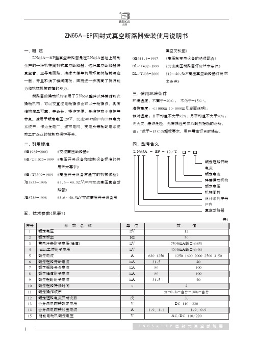
1技术说明(国内) TD-XT-C004-006.R52主要技术参数 订 货 号 L50-EP L80-EP L100-EP 容 积 50L80L 100L设计压力 -0.1~0.28MPa设计温度 142℃ 工作压力 0.23MPa 温度范围 105℃~138℃ 熔解温度 40.0℃~100.0℃ 保温温度40.0℃~134.0℃ 时 间灭菌 0~9999min 保温 0~9999min 预约 0~9999min 内腔尺寸(Φ×L) Φ316×667mm Φ386×695mmΦ386×860mm 外形尺寸(L×W×H) 570×546×990mm 610×546×1030mm 610×546×1195mm腔体材质 06Cr19Ni10不锈钢净 重 75kg 92kg 97kg电 源 AC220V ,50Hz 功 率 5.0kV A 5.3kV A 7.5kV A附 件 不锈钢提篮2个。
ORDERING INFORMATIONProducts to be discontinued.10A PC board type10A TM type60A Screw terminal type80A Connector type300A Connector typeFEATURES1. High-voltage, high-current controlcapable400V DC high-voltage switching cutoffhas been achieved thanks to a sealedconstruction with mixed hydrogen gasand the magnetic arc motion through useof a permanent magnet.2. Compact & Low Operating SoundBy using a capsule contact mechanismthat is enclosed with hydrogen gas, high-capacity cutoff is possible even with a tinycontact gap. There is little operatingsound, which does not change evenwhen large currents are cut off.3. Arc space unnecessaryThe enclosure box can be made smallerthanks to an arc-space-free constructionbeyond which the arc will not go.4. SafetySince the contacts are enclosed in asealed capsule structure, beyond whichthe arc will not go, safety is ensured.5. High contact reliabilityThe contact part is hermetically sealedwith H2 mixed gas, hence the contactresistance remains stable regardless ofthe ambient conditions.6. Mounting direction is not specifiedThe weight of the movable parts is light,and also the restoring force is large,hence the relay is relatively unaffected bygravity.7. Wide selection of models available.Types include PC board type, TM type(10A), screw terminal type (60A), andconnector type (80A and 300A).8. Standard complianceThe 60A type is UL and C-UL standardcertified.TYPICAL APPLICATIONS1. Cogeneration systems2. Battery inspection and testingequipment (charge and dischargecontrol)3. Construction machinery4. AGV (Automatic guided vehicle)(Unmanned transport carts)5. Welding equipment6. Inverter control7. Solar power generation systems8. Elevator, etc.EP RelayContact arrangement1: 1 Form A3: 1 Form A PC board type*5: 1 Form A TM type*AEP0Contact rating1: 10A6: 60A8: 80A9: 300ACoil voltage12:24:48:X0:12V DC24V DC48V DC*100V DC*Note: *10A type onlyTYPES-Specifications: Housing: Yazaki 7283-1020 (light gray); Lead wire: 0.5 mm2 dia. and 300±10 mm length Lead wire coating color: Pin No. 1: white; Pin No. 2: greenRATINGREFERENCE DATA*1Conditions: Varistor used for coil surge absorption. Note: If a diode is used the life will be lower.*2Condition: Switches rated number of 10 cycles each time there is a 2,500A cutoff.*3The upper operation ambient temperature limit is the maximum temperature that can satisfy the coil temperature rise value. Refer to “6. Usage, Storage and Transport Conditions“ in AMBIENT ENVIRONMENT section in Relay Technical Information .1.-(1) Ambient temperature characteristics (10A type)Tested sample: 10A type EP relay, 3pcs1.-(2) Ambient temperature characteristics (60A type)Tested sample: 60A type EP relay, 3pcs1.-(3) Ambient temperature characteristics (80A type)Tested sample: 80A type EP relay, 3pcs1.-(4) Ambient temperature characteristics (300A type)Tested sample: 300A type EP relay, 3pcs 2.-(1) Max. value for switching capacity(10A and 60A types)2.-(2) Max. value for switching capacity(80A and 300A types)ontactcurrent,Aontactcurrent,A3.-(1) Switching life curve (10A type) 3.-(2) Switching life curve (60A type)3.-(3) Switching life curve (80A type)ife(cycle)ife(×13cycle)ife(cycle)3.-(4) Switching life curve (300A type)4. Cut-off curve (forward direction)5.-(1) Carrying performance curve (80︒C)(10A and 60A types) ife(cycle)Cut-off current, Aife(cycle)1010ime,sec5.-(2) Carrying performance curve (80︒C)(80A and 300A types)1010ime,secDIMENSIONS(mm inch) 1. 10A PC board type2. 10A TM type Interested in CAD data? You can obtain CAD data for all products with a mark from your local Panasonic Electric Works representative.CAD DataExternal dimensions CAD DataSchematic (Bottom view)PC board pattern (Bottom view)Notes:1.We recommend through-hole plating withland on both sides.2.Be careful of the insulation distancebetween land patterns with regards to thecircuit voltage you will use.2Load sides have polarities (+) and (-).After doing through-hole plating+0.1+.004General tolerance:Max. 10 .394±0.3 ±.01210 .394 to 50 1.969±0.6 ±.024Min. 50 1.969±1.0 ±.039External dimensionsCAD Data.016Schematic (Top view)Panel cut-off5:CoilLoad sides have polarities (+) and (-).6:CoilMounting hole2-4.2±0.1 dia.General tolerance:Max. 10 .394±0.3 ±.01210 .394 to 50 1.969±0.6 ±.024Min. 50 1.969±1.0 ±.0393. 60A type4. 80A typeExternal dimensionsCAD DataSchematic (Top view)Panel cut-off6: Coil 5: Coil2-1+Load side has polarities (+) and (-).General tolerance:Max. 10 .394 ±0.3 ±.01210 .394 to 50 1.969 ±0.6 ±.024Min. 50 1.969 ±1.0 ±.039External dimensionsCAD Data57.9Schematic (Top view)Panel cut-off*Accessories (included)General tolerance:Max. 10 .394: ±0.3 ±.01210 .394 to 50 1.969: ±0.6 ±.024Min. 50 1.969: ±1.0 ±.039−1Load sides have polarities (+) and (−).5. 300A typeExternal dimensionsCAD DataSchematic (Top view)Panel cut-off*Accessories (included)Max. 10 .394: ±0.3 ±.01210 .394 to 50 1.969: ±0.6 ±.024Min. 50 1.969: ±1.0 ±.039+)−1Input and load sides have polarities (+) and (−).NOTESFor Cautions for Use, see Relay Technical Information.1. When installing the relay, always use washers to prevent the screws from loosening.Tighten each screw within the rated range given below. Exceeding themaximum torque may result in breakage. Mounting is possible in either direction.•M5 screw (60A, 80A and 300A main unit mounting section): 3 to 4N·m •M3.5 screw (60A input terminal): 0.84 to 1.2 N·m•M4 screw (10A PC board type main unit mounting section): 0.98 to 1.2N·m (10A TM type main unit mounting section): 1.8 to 2.7N·mRecommended securing torque on load side terminals•60A/M5 screw: 2.5 to 3.6 N·m •80A/M5 bolt: 3.5 to 6.5 N·m •300A/M8 bolt: 10 to 12 N·m2. The contacts of the relay arepolarized. Please follow instructions in the connection schematic when connecting the contacts.We recommend installing a surgeprotector varistor (ZNR) for the 10A , 60A and 80A types. Avoid using a diode as this may result in decreased cut-off capability.3. Do not use a relay if it has been dropped.4. Avoid mounting the relay in strong magnetic fields (near a transformer or magnet) or close to an object that radiates heat.5. Electrical lifeThis relay is a high-voltage direct-current switch. In its final breakdown mode, it may lose the ability to provide the proper cut-off. Therefore, do not exceed the indicated switching capacity and life. (Please treat the relay as a product with limited life and replace it when necessary.)In the event that the relay loses cut-off ability, there is a possibility that burning may spread to surrounding parts, so configure the layout so that the power is turned off within one second and from the point of view of safety, consider installing a failsafe circuit in the device.Also, in order to avoid increased contact resistance, do not operate when there is no switching load.6. Permeation life of internal gasThis relay uses a hermetically encased contact (capsule contact) with gas inside. The gas has a permeation life that is affected by the temperature inside thecapsule contact (ambient temperature + temperature rise due to flow of electrical current). For this reason, make sure the ambient operating temperature isbetween –40 and 80︒C –40 and +176︒F , and the ambient storage temperature is between –40 and 85︒C –40 and +185︒F .7. Do not disassemble the relay.Please note that disassembling the relay will invalidate the warranty.8. If the power is turned off and then immediately on after applying the rated voltage (current) continuously to therelay’s coil and contact, the resistance of the coil will increase due to a rise in the coil temperature. This causes the pick-up voltage to rise, and possibly exceed the rated pick-up voltage. In thesecircumstances, take measures such as reducing the load current, limiting the duration of current flow, and applying a coil voltage higher than the rated operating voltage.9. Coil operating powerPure DC current should be applied to the coil. The wave form should berectangular. If it includes ripple, the ripple factor should be less than 5%. However, check the actual circuit since thecharacteristics may be slightly different.The power supply waveform supplied to the coil should be rectangular.10. Don’t exceed maximum coil voltage. Exceeding maximumallowable coil voltage on continuous basis will damage the relay and could case failure.11. Ensure that the rated contacts voltage and current values are not exceeded.12. The rated control capacity and life are given as general guides.The contact life is heavily influenced by the type of load and other related conditions, and these factors must be kept in consideration when using the relay.13. Main contact ratings in the ratings apply to when there is a resistive load. If you are using an inductive load (L load) such that L/R > 1 ms, add surge protection in parallel with theinductive load. If this is not done, the electrical life will decrease and cut-off failure may occur.14. Be careful that foreign matter and oils and fats kind don’t stick to the main terminal parts because it is likely to cause terminal parts to give offunusual heat. Also, please use the following materials for connected harnesses and bus bars.•10A TM type: Faston terminal for #187 tab terminal, 0.5 mm board thickness (JIS C2809-1992 compliant, flat type connection terminal)Harness nominal cross-sectional area Load input terminal: min. 2.0 mm 2Coil input terminal: min. 0.3 mm 2•60A and 80A types: Min. 14mm 2 nominal cross sectional area•300A type: Min. 100mm 2 nominal cross sectional area15. Use 40N to 70N of force as a guide to fasten the terminal connected to the 10A TM type. Please use caution when inserting or removing the terminal as the relay tab terminal may cause injuly.16. Place the PC board mount type (10A PC board type) securely by hand soldering after attaching it using M4 screw. Don’t submerge assembled board in cleaning solvent or water. Also, be careful not let flux overflow up from the PC board or adhere to the base of the relay.Recommended hand soldering conditions• Soldering iron: 30 to 60 W • Tip temperature: 400︒C 752︒F• Solder time: within approx. 5 seconds 17. Make sure the power is turned off when wiring.18. Incorrect wiring may causeunexpected malfunction and failure.19. Regarding AC cutoff, although there is no contact polarity, generally it is thought that the electrical life will shorten due to cutoff in the reverse direction, compared to DC cutoff. Confirm electrical life using actual load. In the case of DC cut-off, please note the contact polarity.20. Lead-free solder (tin, silver and copper) is used as pre-solder for the terminals of the PC board mount type (10A PC board type).21. The warranted tensile strength of the female connector lead wire used for connection that comes with the 80A and 300A connector type when attaching it to the relay body is 100N. Avoid excessive tension as this is a cause of broken wires and damage. Also, insert the female connectordeeply and make sure the connection is secure.。
PIE306智能保护装置使用说明书编制:刘贵程审核:批准:目录目录 (3)一.概述 (4)1. 适用范围 (4)2. PIE306智能保护装置主要特点 (4)二、产品命名规则 (5)三.主要技术参数 (6)1. 额定参数 (6)2. 主要技术性能 (6)3. 绝缘、耐压性能 (6)4. 冲击电压 (7)5. 抗电磁干扰性能 (7)6. 环境条件 (7)四.功能 (8)1.控制面板 (8)2.系统菜单说明 (9)3.保护功能说明 (10)4.SOE记录功能 (12)5.通信功能 (13)五.端子定义 (15)六.外形尺寸及开孔图 (17)七.典型接线图(48V供电为例) (18)一.概述1. 适用范围PIE306系列保护装置适用于35KV以下配电网络、变电站、工矿企业变配电室等场合。
2. PIE306智能保护装置主要特点1)具有过流、速断、限时速断三段过流保护、三种反时限过流保护、零序电流保护、二次谐波制动以及三次重合闸功能。
2)具备多个保护定值区切换功能。
3)高可靠性设计,显示功能、保护功能相互独立,无论显示模块如何响应,保护主控功能均不受影响。
4)可测量三相电流、零序电流。
5)可存储100条SOE记录,分辨率:2ms。
6)支持AC/DC220V、DC48V、DC24V多种工作电源,可根据客户需求订制。
7)人机界面友好、专业,彩屏液晶显示,用户可通过按键及液晶屏、指示灯获取装置运行信息、线路电流、开关状态,查询设置保护定值。
8)具备标准485接口,支持101规约、MODBUS等多种规约。
9)通信波特率可以设置,2400-115200均可通信。
10)体积小巧,安装方便,美观大方。
二、产品命名规则三.主要技术参数1. 额定参数1) 保护、测量三相电流参数:额定输入电流(In):5A/1A(可根据用户需求订制)。
最大输入:10In。
过载能力:10A以下,可连续工作;25A,10s;50A,1s。
准确输入范围(精度±5%): 0.1In~10In(±5%)。
EP智能型保护装置使用说明书武汉意瑞莱电气有限公司Wuhan e-relay electric Co.Ltd.V1.0目录1 装置概述 (1)1.1应用范围 (1)1.2功能特点 (1)2. 技术性能参数 (3)2.1工作环境条件 (3)2.2绝缘电阻及介质强度 (3)2.3电气技术参数 (4)2.4抗电磁干扰性能 (6)2.5机械性能 (6)2.6适用的分闸线圈 (7)2.7适用的电流互感器 (7)3 选型说明 (9)4 功能介绍 (10)4.1测量功能 (10)4.2过流保护 (10)4.3速断保护 (14)4.4外部开入量保护和开出量保护 (14)4.5高电流闭锁跳闸 (14)4.6事件记录 (15)5 装置操作说明 (16)5.1人机界面操作 (16)5.2装置接线原理图和端子图 (25)6 装置安装尺寸 (28)随着标准的更新及设计的发展,本说明书所列出的元器件的特性参数可能会改变,我们将不预先作通知。
由我们的技术-销售部门确定这些元器件的特性参数使用范围。
1.装置概述1.1应用范围EP智能型保护装置是一个能执行保护功能的全范围数字保护装置。
根据模式也可以带就地控制、远方控制、电气参数测量、自动化等功能,满足当前和未来对变电和配电站自动化、控制及保护的需要。
本设备用于35KV以下环网柜系统。
可广泛适用于KYN28中置柜,负荷开关柜,真空断路器柜,充气柜等柜型。
装置具有多种动作特性曲线的相过流保护,速断保护,零序过流保护以及外部接点直接跳闸功能,可广泛应用于母线,线路,变压器等保护场合。
1.2 功能特点EP智能型保护装置具有以下功能特点:●全中文液晶显示,人机界面清晰友好,调试方便,操作简单。
●具有完善的硬件自检功能,方便调试与维护。
●装置可以选择自供电(由电流互感器取电)方式,免除因安装直流屏或UPS而带来的额外负担。
●装置除可选择自供电(由电流互感器取电)方式外,还提供了AC110~AC220,DC24~DC220多种电源接口,增强了用户选择电源的灵活性。
几种电源可同时使用,互不干扰,大大增强了供电的稳定性。
●装置具有IEC多种动作特性曲线的相过流保护,速断保护,零序过流保护以及外部接点直接跳闸功能。
●装置可适用于多种类型的分闸线圈,包括双稳态线圈,DC24V,DC48V,DC110V,DC220V单稳态电压型线圈以及电流型线圈。
●装置使用灵活,各种保护功能用户可以通过控制字来选择投入或退出。
●装置可以在线监视三相电流,零序电流,开入开出接点的状态,保证了装置工作的可靠性。
●高精度进口元器件以及完善的生产工艺保证装置的精确性,可靠性以及长久的使用寿命。
●装置前端提供RS-232通讯接口,以及选配的后端子RS-485接口,向用户提供开放的通讯协议,方便用户进行远程监控。
●装置结构紧凑,按抗振动、防尘密封设计,适合在环境条件较为恶劣的现场运行。
2. 技术性能参数2.1 工作环境条件●环境温度1.工作温度:-20︒C - +65︒C(注:装置在-40︒C的低温环境下均能可靠动作,起保护作用,前面液晶不能正常显示,待温度升高到-20︒C时即可正常显示) 2.存储温度 -40︒C - +80︒C●相对湿度5% -- 95%●大气压力 70KPa -- 110KPa●海拔高度海拔4000米以下2.2绝缘电阻及介质强度绝缘电阻:装置的电源回路、交流回路、开出回路、外壳相互之间用开路电压500V的兆欧表测量其绝缘电阻值,正常试验大气条件下,各回路绝缘电阻不小于100MΩ。
介质强度:在正常试验大气条件下,保护装置电源回路、交流回路、开出回路、外壳相互之间能承受频率50HZ,电压2KV,历时1分钟的工频耐压试验而无闪络击穿现象。
冲击电压:在正常试验大气条件下,保护装置电源回路、交流回路、开出回路、外壳相互之间能承受1.2/50µs的标准雷电波短时冲击电压试验,开路试验电压5KV。
湿热性能:耐湿热性能符合GB7261。
2.3电气技术参数1.额定数据:交流电流5A/1A频率50/60Hz电源AC220(AC110) +20%DC220(DC110) +20%DC24V~DC48V +20%自供电(由相电流互感器取电) 2.功率消耗:外部供电时不大于20W自供电时不大于1V A3.过载能力:2倍额定电流连续工作10倍额定电流允许10S30倍额定电流允许1S4.测量精度:相电流<+1%零序电流<0.005A5.测量范围:0..1In~20In6.开入回路:为无源干结点回路,不需要串接外部电源7.开出回路:电压类型可定制8.通信接口前端RS-232(标配)后端RS485(选配)2.4 抗电磁干扰性能装置能够通过以下几种国家、国际标准的抗电磁干扰实验:●静电放电干扰:装置能承受IEC255-22-2标准规定的静电放电试验●电磁场辐射干扰:装置能承受IEC255-22-3标准规定的电磁场辐射试验●快速瞬变干扰:装置能承受IEC255-22-4标准规定的快速瞬变干扰试验●脉冲群干扰:装置能承受试验电源频率为100KHZ和1MHZ,试验电压为共模2500V,差模1000V的衰减振荡波而不拒动、不误动。
2.5 机械性能振动:装置能承受GB7261规定的严酷等级为I级的振动耐久能力试验冲击:装置能承受GB7261规定的严酷等级为I级的冲击耐久能力试验碰撞:装置能承受GB7261规定的严酷等级为I级的碰撞耐久能力试验2.6 适用的分闸线圈机构类型:单稳态,双稳态电压等级:AC/DC24V 48V 110V 220V电气类型:电压型电流型常见类型如图2-1所示:图2-1单稳态单稳态双稳态单稳态DC220V 电流型 DC24V AC220V 电压型用户订货时需提供分闸线圈的类型。
2.7 适用的电流互感器适用的电流互感器类型:穿芯式,开启式,浇注式,如图2-2所示:图2-2穿芯式开启式浇注式用户订货时需提供电流互感器的型号,电流比,准确级和额定负载等参数。
3 选型说明举例:适用于智能柜型,具备曲线保护,速断保护,采用自供电源,不具备通讯口,采用24V 单稳态线圈,右出线方式的型号为EPH-10A-024-LEP适用柜型S --真空断路器柜R --熔断器保护柜保护功能10--曲线保护+速断保护20--曲线保护+速断保护+零序保护通讯方式0无通讯口1RS232通信GPRS 通信供电电源A 自供电源(电流互感器取电)B --AC110V~220VC DC24V~DC220VD 分闸线圈12双稳态线圈2424V 单稳态线圈48110V 单稳态线圈110220------自供电源+AC110~220V 自供电源+DC24V~DC220VE ----------23--48V 单稳态线圈220V 单稳态线圈----------外形尺寸(宽*深*高)W L --智能型(柜型可选择)H --RS232通信+RS485通信174mm*155mm*88mm(柜门安装,上出线)106mm*155mm*156mm(柜门安装,右出线)4 功能介绍4.1测量功能EP智能型保护装置测量所得的电流值对应于每一相电流有效值:I1,I2和I3。
半个波中使用八个采样点及五个连续半波的计算平均值。
系统每秒更新测量数据。
从5A到电流互感器最大额定功率范围120%的测量精度均为1级。
零序电流的测量方式和相电流相同。
采用交流不间断采样和傅立叶算法,具有实时性强、计算精度高等优点。
4.2过流保护保护装置执行的过电流保护功能如下:·相过流保护功能(51)·零序过流保护功能(51N)·相速断保护(50)·零序速断保护(50N)●相过流保护(51):相过电流保护的方式采用定时限过流和反时限过流。
定时限和反时限的动作曲线可参照图4-1,图4-2,图4-3,图4-4。
●零序过流保护(51N):零序过流保护主要用于中性点绝缘或补偿的系统,由于非直接接地系统中零序电流一般比较小,要求装置检测零序电流的精度相对比较高,尤其是长电缆系统中电容电流比较大,因此零序电流互感器的变比应选择较小,一般选择相互感器变比的1/10。
零序过流保护的动作曲线也可参照图4-1,图4-2,图4-3,图4-4。
其中:In*I>表示电流整定值I表示电流动作值K表示曲线因数相过流保护和零序过流保护功能均可以在装置内部选择投入或退出。
图4-1 定时限曲线相电流时间零序电流时间图4-2 一般反时限曲线相电流时间零序电流时间图4-3 甚反时限曲线相电流时间零序电流时间图4-4 极反时曲线相电流时间零序电流时间4.3速断保护●相速断保护(50):当有相接地故障或相与相之间短接时,会产生高于额定电流几倍甚至几十倍的电流,保护装置会通过整定的时间后跳闸。
本装置的分闸电流和分闸时间均可整定,分闸时间最短可整定为0.05S。
●零序速断保护(50N):零序速断保护功能与相速断保护功能执行方式一致。
相速断保护和零序速断保护功能在保护装置内部均可选择投入或退出。
4.4外部开入量保护和开出量保护装置具有5个数字式无源接点输入和3个开出量。
无源接点输入的延时时间可以设定,设定范围为0.01S~60S可调,此项功能主要用在变压器的过温保护,重瓦斯保护,事故告警,同时亦可作为手动分闸按钮。
4.5高电流闭锁跳闸该项功能主要应用于负荷开关+熔断器场合,由于负荷开关不具有开断短路电流能力,因此当该功能投入时,负载电流大于设定闭锁电流时装置将闭锁所有保护功能,使得故障由熔断器切除,保证负荷开关不致损坏。
这种配置可以同时满足短路故障切除及过负载切除要求。
4.6事件记录装置可提供多达30次的故障记录,包括过流故障,速断故障,开关量输入变位,设备故障等各种类型事件。
每条事件记录包含了事件发生的时间(精确到秒),时间发生时的电气参数值,各种开关量输入状态值等信息。
此信息记录于FLASH芯片中,装置掉电不会丢失事件信息。
事件记录按照发生时间的先后顺序进行存储。
当时间记录事件数量超过最大记录值时,装置自动用最新的记录覆盖最旧的记录。
在装置的液晶屏中可以查看各条事件记录内容,也可通过通讯总线上传记录。
5 装置操作说明5.1人机界面操作装置具有两种人机界面操作方式:一种是本机的人机界面操作,包括信号指示灯,轻触小键盘,大屏幕汉字液晶显示;另一种时通过后台调试软件实现人机界面操作。
本节仅介绍本机人机界面操作。
5.1.1.信号指示灯装置向用户提供1个信号指示灯。
其有三种指示状态:●指示灯恒亮:表明装置处于正常工作状态。
●指示灯闪烁:表明装置供电不足。
●指示灯熄灭,供电不足或装置故障。
5.1.2.轻触小键盘装置面板下方有6个轻触小键盘,分别为“SET”(确认),“ESC”(退出),“上”键用于上移光标或修改参数时递增,“下”键用于下移光标或修改参数时递减。