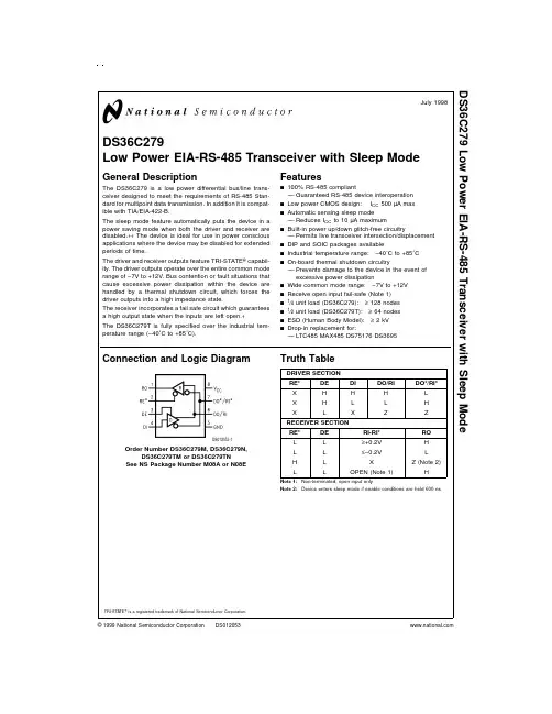
General DescriptionThe DS7505 low-voltage (1.7V to 3.7V) digital ther-mometer and thermostat provides 9-, 10-, 11-, or 12-bit digital temperature readings over a -55°C to +125°C range with ±0.5°C accuracy over a -0°C to +70°C range.A 9-bit resolution mode is software compatible with the LM75. Communication with the DS7505 is achieved through a simple 2-wire serial interface. Three address pins allow up to eight DS7505 devices to operate on the same 2-wire bus, which greatly simplifies distributed temperature-sensing applications.The DS7505 thermostat has a dedicated open-drain out-put (O.S.) and programmable fault tolerance, which allows the user to define the number of consecutive error conditions that must occur before O.S. is activated.There are two thermostatic operating modes that control thermostat operation based on user-defined trip points (T OS and T HYST ) that are stored in EEPROM registers.ApplicationsNetworking Equipment Cellular Base Stations Office Equipment Medical EquipmentAny Thermally Sensitive SystemFeatures♦Operating Range from 1.7V to 3.7V♦Temperature Measurements Require No External Components ♦Measures Temperatures from -55°C to +125°C (-67°F to +257°F)♦±0.5°C Accuracy Over a 0°C to +70°C Range ♦Thermometer Resolution is User-Configurable from 9 (Default) to 12 Bits (0.5°C to 0.0625°C Resolution)♦9-Bit Conversion Time is 25ms (max)♦Thermostatic Settings are User-Definable and Nonvolatile (NV)♦Stand-Alone Thermostat Capability♦Data Read/Write Occurs Through a 2-Wire Serial Interface (SDA and SCL Pins)♦Data Lines Filtered Internally for Noise Immunity (50ns Deglitch)♦Optional Bus Timeout Feature Prevents Lockup Problems on 2-Wire Interface ♦Multidrop Capability Simplifies Distributed Temperature-Sensing Applications ♦Pin/Software Compatible with the LM75♦Available in 8-Pin SO and µMAX ®PackagesDS7505Digital Thermometer and Thermostat________________________________________________________________Maxim Integrated Products 1Pin ConfigurationsOrdering InformationRev 1; 3/08For pricing, delivery, and ordering information, please contact Maxim Direct at 1-888-629-4642,or visit Maxim’s website at .+Denotes a lead-free package.T&R = Tape and reel.µMAX is a registered trademark of Maxim Integrated Products, Inc.Commands are capitalized for clarity.D S 7505Digital Thermometer and Thermostat 2_______________________________________________________________________________________ABSOLUTE MAXIMUM RATINGSDC ELECTRICAL CHARACTERISTICSStresses beyond those listed under “Absolute Maximum Ratings” may cause permanent damage to the device. These are stress ratings only, and functional operation of the device at these or any other conditions beyond those indicated in the operational sections of the specifications is not implied. Exposure to absolute maximum rating conditions for extended periods may affect device reliability.Voltage Range on VDD Relative to Ground ..........-0.3V to +4.0V Voltage Range on Any Other PinRelative to Ground.............................................-0.3V to +6.0VOperating Temperature Range .........................-55°C to +125°C Storage Temperature Range.............................-55°C to +125°C Soldering Temperature...........................Refer to the IPC/JEDECJ-STD-020 Specification.AC ELECTRICAL CHARACTERISTICSDS7505Digital Thermometer and Thermostat_______________________________________________________________________________________3max-rated current.Note 3:Specified in 12-bit conversion mode. Quantization error must be considered when converting in lower resolutions.Note 4:I DD specified with O.S. pin open.Note 5:I DD specified with V DD at 3.0V and SDA, SCL = 3.0V, T A = -55°C to +85°C.Note 6:I DD specified with A0, A1, A2 = 0V or V DD .Note 7:V DD must be > 2.0V.Note 8:E 2Copy occurs at +25°C.Note 9:See the timing diagram (Figure 1). All timing is referenced to 0.9 x V DD and 0.1 x V DD .Note 10:After this period, the first clock pulse is generated.Note 11:The DS7505 provides an internal hold time of at least 75ns on the SDA signal to bridge the undefined region of SCL’s falling edge.Note 12:For example, if C B = 300pF, then t R(MIN)= t F(MIN)= 50ns.Note 13:This timeout applies only when the DS7505 is holding SDA low. Other devices can hold SDA low indefinitely and the DS7505 does not reset.AC ELECTRICAL CHARACTERISTICS (continued)D S 7505Digital Thermometer and Thermostat 4_______________________________________________________________________________________Figure 1. Timing DiagramFigure 2. Block DiagramDS7505Digital Thermometer and Thermostat_______________________________________________________________________________________5OS HYSTOperation ⎯MeasuringTemperatureThe DS7505 measures temperature using a bandgap temperature-sensing architecture. An on-board delta-sigma analog-to-digital converter (ADC) converts the measured temperature to a digital value that is calibrat-ed in degrees Celsius; for Fahrenheit applications a lookup table or conversion routine must be used. The DS7505 is factory-calibrated and requires no external components to measure temperature.The DS7505 can be configured to power up either automatically converting temperature or in a low-power standby state. The preferred power-up mode can be set using the SD bit in the configuration register as explained in the Configuration Register section. The resolution of the digital output data is user-configurable to 9, 10, 11, or 12 bits, corresponding to temperature increments of 0.5°C, 0.25°C, 0.125°C, and 0.0625°C,respectively. The factory default resolution at power-up is 9 bits (R1 = 0, R0 = 0), however this can be pro-grammed to 10, 11, or 12 bits using the R0 and R1 bits in the configuration register as explained in the Configuration Register section. Note that the conver-sion time doubles for each additional bit of resolution.After each temperature measurement and analog-to-digital (A/D) conversion, the DS7505 stores the temper-ature as a 16-bit two’s complement number in the 2-byte temperature register (see Figure 3). The sign bit (S) indicates if the temperature is positive or negative:for positive numbers S = 0 and for negative numbers S = 1. The most recently converted digital measurement can be read from the temperature register at any time.Since temperature conversions are performed in the background, reading the temperature register does not affect the operation in progress.Bits 3 through 0 of the temperature register are hard-wired to 0. When the DS7505 is configured for 12-bit resolution, the 12 MSBs (bits 15 through 4) of the tem-perature register contain temperature data. For 11-bit resolution, the 11 MSBs (bits 15 through 5) of the tem-perature register contain data, and bit 4 reads out as 0.Likewise, for 10-bit resolution, the 10 MSBs (bits 15through 6) contain data, and for 9-bit the 9 MSBs (bits 15 through 7) contain data and all unused LSBs con-tains 0s. Table 1 gives examples of 12-bit resolution dig-ital output data and the corresponding temperatures.D S 7505Shutdown ModeFor power-sensitive applications, the DS7505 offers a low-power shutdown mode. The SD bit in the configura-tion register controls shutdown mode. When SD is pro-grammed to 1, the conversion in progress is completed and the result stored in the temperature register, after which the DS7505 goes into a low-power standby state.The O.S. output is cleared if the thermostat is operating in interrupt mode and O.S remains unchanged in com-parator mode. The 2-wire interface remains operational in shutdown mode, and writing a 0 to the SD bit returns the DS7505 to normal operation. Upon power-up in shutdown mode, the DS7505 executes one tempera-ture measurement. The result is stored in the tempera-ture register, after which the DS7505 enters the shutdown state.Operation ⎯ThermostatThe DS7505 thermostat can be programmed to power up in either comparator mode or interrupt mode, which activate and deactivate the open-drain thermostat out-put (O.S.) based on user-programmable trip points (T OS and T HYST ). The T HYST and T OS registers contain Celsius temperature values in two’s complement format and consist of EEPROM that is shadowed by SRAM.Once written to the shadow SRAM, values can be stored in EEPROM by issuance of a Copy Data com-mand from the master (see the Command Set section for more details). The device can operate using the shadow SRAM only or using the EEPROM. If the EEPROM is used, the values are NV and can be pro-grammed prior to installation of the DS7505 for stand-alone operation. The factory power-up settings for the DS7505 are with the thermostat in comparator mode,active-low O.S. polarity, overtemperature trip-point (T OS ) register set to 80°C, the hysteresis trip-point (T HYST ) register set to +75°C, and the number of con-secutive conversion to trigger O.S. set to 1. If these power-up settings are compatible with the application,the DS7505 can be used as a stand-alone thermostat (i.e., no 2-wire communication required) with no pro-gramming required prior to installation. If interrupt mode operation, active-high O.S. polarity, different T OS and T HYST values, or a different number of conversions to trigger O.S. are desired, they must be programmedinto the EEPROM either after initial power-up or prior to IC installation. The programmed values then become the new power-up defaults.In both operating modes, the user can program the thermostat-fault tolerance, which sets how many con-secutive temperature readings (1, 2, 4, or 6) must fall outside the thermostat limits before the thermostat out-put is triggered. The fault tolerance is set by the F1 and F0 bits in the configuration register. The default factory power-up setting for fault tolerance is 1 (F1 = 0, F0 = 0).The data format of the T OS and T HYST registers is iden-tical to that of the temperature register (see Figure 3),i.e., a 2-byte two’s complement representation of the trip-point temperature in degrees Celsius with bits 3through 0 hardwired to 0. After every temperature con-version, the measurement is compared to the values stored in the T OS and T HYST registers. The O.S. output is updated based on the result of the comparison and the operating mode of the IC. The number of T OS and T HYST bits used during the thermostat comparison is equal to the conversion resolution set by the R1 and R0bits in the configuration register. For example, if the resolution is 9 bits, only the 9 MSBs of T OS and T HYST are used by the thermostat comparator.The active state of the O.S. output can be programmed by the POL bit in the configuration register. The power-up factory default is active low (POL = 0).If the user does not wish to use the thermostat capabili-ties of the DS7505, the O.S. output should be left unconnected. Note that if the thermostat is not used,the T OS and T HYST registers can be used for general storage of system data.Comparator ModeWhen the thermostat is in comparator mode, O.S. can be programmed to operate with any amount of hystere-sis. The O.S. output becomes active when the mea-sured temperature exceeds the T OS value a consecutive number of times as defined by the F1 and F0 fault tolerance (FT) bits in the configuration register.O.S. then stays active until the first time the tempera-ture falls below the value stored in T HYST . Putting the device into shutdown mode does not clear O.S. in com-parator mode. Thermostat comparator mode operation with FT = 2 is illustrated in Figure 4.Digital Thermometer and Thermostat 6_______________________________________________________________________________________DS7505Digital Thermometer and Thermostat_______________________________________________________________________________________7Interrupt ModeIn interrupt mode, the O.S. output first becomes active when the measured temperature exceeds the T OS value a consecutive number of times equal to the FT value in the configuration register. Once activated, O.S.can only be cleared by either putting the DS7505 into shutdown mode or by reading from any register (tem-perature, configuration, T OS , or T HYST ) on the device.Once O.S. has been deactivated, it is only reactivatedwhen the measured temperature falls below the T HYST value a consecutive number of times equal to the FT value. Again, O.S can only be cleared by putting the device into shutdown mode or reading any register.Thus, this interrupt/clear process is cyclical between T OS and T HYST events (i.e, T OS , clear, T HYST , clear,T OS , clear, T HYST , clear, etc.). Thermostat interrupt mode operation with FT = 2 is illustrated in Figure 4.D S 7505Configuration RegisterThe configuration register allows the user to program various DS7505 options such as conversion resolution,thermostat fault tolerance, thermostat polarity, thermo-stat operating mode, and shutdown mode. The configu-ration register is arranged as shown in Figure 5 and detailed descriptions of each bit are provided in Table 2. The user has read/write access to all bits in the con-figuration register except the MSB (NVB bit), which is aread-only bit. All bits in the register but the NVB bit are NV EEPROM backed by shadow SRAM, and thus power-up in their programmed state. Once written to the shadow SRAM, values can be stored in EEPROM by issuance of a Copy Data command from the master (see the Command Set section for more details). If the values are not copied to the EEPROM, the device pow-ers up with the factory default settings or the last values that were copied to the EEPROM. The NVB bit is SRAM and powers up in the state shown in Table 2.Digital Thermometer and Thermostat 8_______________________________________________________________________________________Figure 5. Configuration RegisterRegister Pointer The four DS7505 registers each have a unique 2-bit pointer designation, which is defined in Table 5. When reading from or writing to the DS7505, the user must “point” the DS7505 to the register that is to be accessed. When reading from the DS7505, once the pointer is set, it remains pointed at the same register until it is changed. For example, if the user desires to perform consecutive reads from the temperature regis-ter, then the pointer only has to be set to the tempera-ture register one time, after which all reads are automatically from the temperature register until the pointer value is changed. When writing to the DS7505, the pointer value must be refreshed each time a write is performed, even if the same register is being written to twice in a row.At power-up, the pointer defaults to the temperature register location. The temperature register can be read immediately without resetting the pointer.Changes to the pointer setting are accomplished as described in the 2-Wire Serial Data Bus section.2-Wire Serial Data Bus The DS7505 communicates over a standard bidirection-al 2-wire serial data bus that consists of a serial clock (SCL) signal and serial data (SDA) signal. The DS7505 interfaces to the bus through the SCL input pin and open-drain SDA I/O pin. All communication is MSB first. The following terminology is used to describe 2-wire communication:M aster Device:Microprocessor/microcontroller thatcontrols the slave devices on the bus. The masterdevice generates the SCL signal and START and STOPconditions.Slave:All devices on the bus other than the master.The DS7505 always functions as a slave.Bus Idle or Not Busy:Both SDA and SCL remain high.SDA is held high by a pullup resistor when the bus isidle, and SCL must either be forced high by the master(if the SCL output is push-pull) or pulled high by apullup resistor (if the SCL output is open drain).Transmitter:A device (master or slave) that is sendingdata on the bus.Receiver:A device (master or slave) that is receivingdata from the bus.START Condition:Signal generated by the master toindicate the beginning of a data transfer on the bus.The master generates a START condition by pullingSDA from high to low while SCL is high (see Figure 6).A “repeated” START is sometimes used at the end of adata transfer (instead of a STOP) to indicate that themaster performs another operation.STOP Condition:Signal generated by the master toindicate the end of a data transfer on the bus. The mas-ter generates a STOP condition by transitioning SDAfrom low to high while SCL is high (see Figure 6). Afterthe STOP is issued, the master releases the bus to itsidle state.Acknowledge (ACK):When a device (either master orslave) is acting as a receiver, it must generate anacknowledge (ACK) on the SDA line after receivingevery byte of data. The receiving device performs anACK by pulling the SDA line low for an entire SCL peri-od (see Figure 6). During the ACK clock cycle, thetransmitting device must release SDA. A variation onthe ACK signal is the “not acknowledge” (NACK). Whenthe master device is acting as a receiver, it uses aNACK instead of an ACK after the last data byte to indi-cate that it is finished receiving data. The master indi-cates a NACK by leaving the SDA line high during theACK clock cycle.DS7505 Digital Thermometer and Thermostat9D S 7505Slave Address:Every slave device on the bus has a unique 7-bit address that allows the master to access that device. The DS7505’s 7-bit bus address is 1 0 0 1A 2A 1A 0, where A 2, A 1, and A 0 are user-selectable through the corresponding input pins. The three address pins allow up to eight DS7505s to be mul-tidropped on the same bus.Address Byte:The control byte is transmitted by the master and consists of the 7-bit slave address plus aread/write (R/W ) bit (see Figure 7). If the master is going to read data from the slave device then R/W = 1,and if the master is going to write data to the slave device then R/W = 0.Pointer Byte:The pointer byte is used by the master to tell the DS7505 which register is going to be accessed during communication. The six MSBs of the pointer byte (see Figure 8) are always 0 and the two LSBs cor-respond to the desired register as shown in Figure 8.Digital Thermometer and Thermostat10______________________________________________________________________________________General 2-Wire Information •All data is transmitted MSB first over the 2-wire bus.•One bit of data is transmitted on the 2-wire bus each SCL period.•A pullup resistor is required on the SDA line, and, when the bus is idle, both SDA and SCL must remain in a logic-high state.•All bus communication must be initiated with a START condition and terminated with a STOP condi-tion. During a START or STOP is the only time SDA is allowed to change states while SCL is high. At all other times, changes on the SDA line can only occur when SCL is low; SDA must remain stable when SCL is high.•After every 8-bit (1-byte) transfer, the receiving device must answer with an ACK (or NACK), which takes one SCL period. Therefore, nine clocks are required for every 1-byte data transfer.Writing to the DS7505:To write to the DS7505, the master must generate a START followed by an address byte containing the DS7505 bus address. The value of the R/W bit must be a 0, which indicates that a write is about to take place. The DS7505 responds with an ACK after receiving the address byte. The master then sends a pointer byte which tells the DS7505 which reg-ister is being written to. The DS7505 again responds with an ACK after receiving the pointer byte. Following this ACK the master device must immediately begin transmitting data to the DS7505. When writing to the configuration register, the master must send one byte of data (see Figure 9B), and when writing to the T OS or T HYST registers the master must send two bytes of data (see Figure 9C). After receiving each data byte, the DS7505 responds with an ACK, and the transaction is finished with a STOP from the master. All writes to the DS7505 are made to shadow SRAM. Once data is writ-ten to the shadow SRAM, it is only stored to EEPROM by issuance of a Copy Data command from the master. At that time, all registers are copied to EEPROM except the Temperature register which is SRAM only.Reading from the DS7505:When reading from the DS7505, if the pointer was already pointed to the desired register during a previous transaction, the read can be performed immediately without changing the pointer setting. In this case the master sends a START followed by an address byte containing the DS7505 bus address. The R/W bit must be a 1, which tells the DS7505 that a read is being performed. After the DS7505 sends an ACK in response to the address byte, the DS7505 begins transmitting the requesteddata on the next clock cycle. When reading from the configuration register, the DS7505 transmits one byte of data, after which the master must respond with a NACK followed by a STOP (see Figure 9E). For two-byte reads(i.e., from the temperature, T OS or T HYST register), theDS7505 transmits two bytes of data, and the mastermust respond to the first data byte with an ACK and tothe second byte with a NACK followed by a STOP (see Figure 9A). If only the most significant byte of data is needed, the master can issue a NACK followed by a STOP after reading the first data byte in which case the transaction is the same as for a read from the configu-ration register.If the pointer is not already pointing to the desired reg-ister, the pointer must first be updated as shown in Figure 9D, which shows a pointer update followed by asingle-byte read. The value of the R/W bit in the initial address byte is a 0 (“write”) since the master is goingto write a pointer byte to the DS7505. After the DS7505 responds to the address byte with an ACK, the mastersends a pointer byte that corresponds to the desired register. The master must then perform a repeated start followed by a standard one or two byte read sequence(with R/W=1) as described in the previous paragraph.The Recall Data command should be issued before aread if assurance is needed that the contents of the EEPROM in the Shadow SRAM when read.Bus Timeout:The DS7505 has a bus timeout featurethat prevents communication errors from leaving the ICin a state where SDA is held low disrupting other devices on the bus. If the DS7505 holds the SDA linelow for a period of t TIMEOUT, its bus interface automati-cally resets and release the SDA line. Bus communica-tion frequency must be fast enough to prevent a reset during normal operation. The bus timeout feature only applies to when the DS7505 is holding SDA low. Other devices can hold SDA low for an undefined period with-out causing the interface to reset.Command SetRecall Data [B8h]1011 1000Refreshes SRAM shadow register with EEPROM data. Itis recommended that a Recall command be performed before reading EEPROM-backed memory locations.The master sends a START followed by an addressbyte containing the DS7505 bus address. The R/W bitmust be a 0. The DS7505 responds with an ACK. If thenext byte is a 0xB8, the DS7505 recalls all EEPROMdata into shadow RAM locations.DS7505Digital Thermometer and Thermostat ______________________________________________________________________________________11D S 7505Copy Data [48h]0100 1000Copies data from all SRAM shadow registers to EEPROM. It is recommended that a Copy Data com-mand be performed after writing EEPROM-backed memory locations to guarantee data integrity in the event of a power loss. The master sends a START fol-lowed by an address byte containing the DS7505 bus address. The R/W bit must be a 0. The DS7505responds with an ACK. If the next byte is a 0x48, the DS7505 copies all Shadow RAM locations in EEPROM memory.Software POR [54h]0101 0100The master sends a START followed by an address byte containing the DS7505 bus address. The R/W bit must be a 0. The DS7505 responds with an ACK. If the next byte is a 0x54, the DS7505 resets as if power had been cycled, which stops temperature conversions and resets all registers to their power-up states. No ACK is sent by the IC after the POR command is received.Afterwards, the DS7505 makes a single temperature conversion or continuous temperature conversions,depending on the state of the SD bit.Digital Thermometer and Thermostat 12______________________________________________________________________________________Figure 9. 2-Wire Interface TimingDS7505Digital Thermometer and Thermostat______________________________________________________________________________________13Package Information(For the latest package outline information, go to /DallasPackInfo .)21-0036PACKAGE TYPE DOCUMENT NO.8 SO (150 mils)56-G2008-0018 µMAXD S 7505Digital Thermometer and Thermostat Maxim cannot assume responsibility for use of any circuitry other than circuitry entirely embodied in a Maxim product. No circuit patent licenses are implied. Maxim reserves the right to change the circuitry and specifications without notice at any time.14____________________Maxim Integrated Products, 120 San Gabriel Drive, Sunnyvale, CA 94086 408-737-7600©2008 Maxim Integrated Productsis a registered trademark of Maxim Integrated Products, Inc.I。