实验三-交换机、路由器配置实验
- 格式:doc
- 大小:731.00 KB
- 文档页数:11
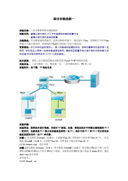
综合实验选做一实验名称:三层交换机和路由器的路由试验目的:掌握三层交换机S V I方式连接路由器的配置方法掌握三层交换机路由的配置功能描述:在分散连接的系统中,在跨交换机环境下,通过划分Vlan,实现属于不同Vlan 的端口不能互相访问,而相同的VLAN内的端口可以互相访问。
背景描述:你们中学校园采用核心、接入两层结构组建的网络,现学校需要将校园网接入互联网,学校在出口使用一台路由器连接互联网。
请做相应配置实现三层交换机和路由器之间的互通,并实现内部网络中V L A N之间的通信。
技术原理:利用三层交换机的路由功能实现VLAN和IP网络的关联。
实验设备:三层交换机一台,路由器一台,二层交换机两台,PC机三台实验拓扑:如下图,IP地址自定实验步骤:实验准备:按照拓扑进行连线。
并进行IP规划。
注意:要保证拓扑中和路由器连接的PC3一直存在,也就是说PC3要占用实验室里面的一台PC。
拓扑中的PC1和PC2可以利用实验室里面的另外一台PC来代替。
步骤1.在交换机SwitchA(2126-1)上创建Vlan 10,并将0/2口划分到Vlan 10 中,在交换机SwitchB(2126-2)上创建Vlan 20,并将0/2口划分到Vlan 20 中。
s2126-1#show vlan 进行查看步骤2.把交换机SwitchA(2126-1)和交换机SwitchB(2126-2)各自通过F0/22口和三层交换机S3760的F0/12口以及F0/22口相连。
并将各自的F0/22接口设定为trunk模式。
通过show vlan命令查看。
参考命令:s2126-1#conf ters2126-1(config)#interface fastethernet0/22s2126-1(config-if)#switch mode trunk步骤3.在三层交换机3760上创建VLAN 10和VLAN 20 和VLAN 30。
将与二层交换机相连接的F0/22和F0/12口,设为trunk模式。

一、实训目的通过本次实训,掌握路由器的基本配置方法,了解路由器在网络中的作用,提高网络设备的配置与管理能力。
二、实训环境1. 路由器:华为AR系列路由器一台2. 交换机:华为S系列交换机一台3. 网线:直通网线若干4. 计算机若干5. 实验室网络环境:模拟企业局域网环境三、实训内容1. 路由器基本配置2. 路由器接口配置3. 路由协议配置4. 静态路由配置5. 动态路由配置6. 路由策略配置7. NAT配置8. 路由器安全配置四、实训步骤1. 路由器基本配置(1)连接路由器与计算机,使用Console线进入路由器配置模式。
(2)配置路由器基本参数,包括主机名、密码等。
(3)配置接口IP地址,确保路由器与交换机之间能够正常通信。
2. 路由器接口配置(1)查看路由器接口信息,了解接口状态。
(2)配置接口VLAN,实现不同VLAN之间的隔离。
(3)配置接口安全特性,如MAC地址绑定、IP源地址过滤等。
3. 路由协议配置(1)配置静态路由,实现不同网络之间的互通。
(2)配置动态路由协议,如RIP、OSPF等,实现网络自动路由。
4. 静态路由配置(1)查看路由表,了解当前网络的路由信息。
(2)配置静态路由,实现特定网络之间的互通。
5. 动态路由配置(1)配置RIP协议,实现网络自动路由。
(2)配置OSPF协议,实现网络自动路由。
6. 路由策略配置(1)配置路由策略,实现特定数据包的转发。
(2)配置策略路由,实现不同数据包的转发。
7. NAT配置(1)配置NAT地址池,实现内部网络访问外部网络。
(2)配置NAT转换,实现内部网络访问外部网络。
8. 路由器安全配置(1)配置ACL,实现访问控制。
(2)配置IPsec VPN,实现远程访问。
(3)配置端口安全,防止未授权访问。
五、实训结果通过本次实训,成功配置了路由器的基本参数、接口、路由协议、静态路由、动态路由、路由策略、NAT和路由器安全配置。
实现了不同网络之间的互通,满足了网络需求。
计算机网络实验课程实验报告
实验名称路由器配置
一、实验目的
1、掌握路由器的基本配置及常用命令;
2、理解网络地址规划的原则及方法。
二、实验所用仪器(或实验环境)
路由器1台,交换机2台,PC机至少4台,RJ45双绞线。
Console控制电缆。
本次使用cisco packet tracer进行仿真。
三、实验基本原理及步骤(或方案设计及理论计算)
1、直连路由:用2个交换机组建两个LAN,用路由器将两个LAN连接;
2、基于三层交换机的VLAN间路由:用1个三层交换机组建两个LAN,用三层交换机的端口路由功能实现VLAN间的路由。
3、单臂路由:用1个二层交换机组建两个LAN,用路由器将两个LAN连接;(选作,有些设备不支持)
4、规划设置PC机的IP地址和掩码。
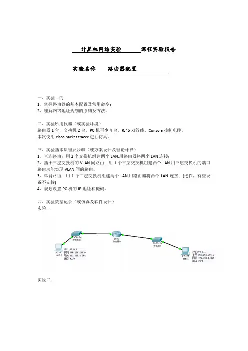
四、实验数据记录(或仿真及软件设计)
实验一
实验二
实验三
五、实验结果分析及回答问题(或测试环境及测试结果)实验一
实验二实验三
六、心得体会
可以熟练使用常用的路由器的操作指令;对于LAN和VLAN有了更深的理解和认识。
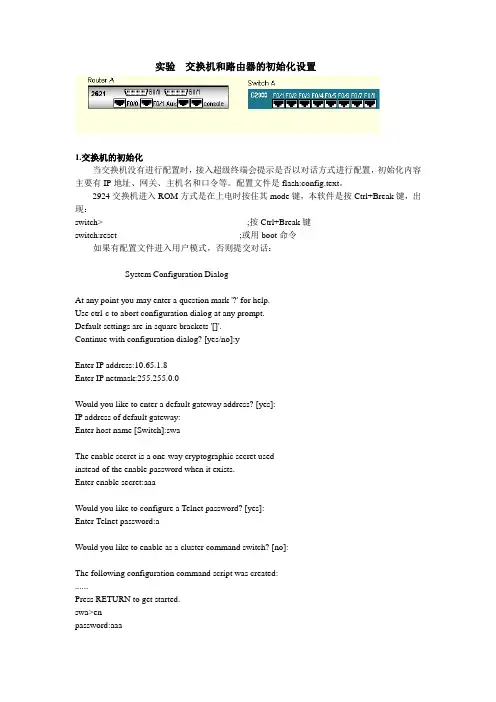
实验交换机和路由器的初始化设置1.交换机的初始化当交换机没有进行配置时,接入超级终端会提示是否以对话方式进行配置,初始化内容主要有IP地址、网关、主机名和口令等。
配置文件是flash:config.text。
2924交换机进入ROM方式是在上电时按住其mode键,本软件是按Ctrl+Break键,出现:switch> ;按Ctrl+Break键switch:reset ;或用boot命令如果有配置文件进入用户模式,否则提交对话:--- System Configuration Dialog ---At any point you may enter a question mark '?' for help.Use ctrl-c to abort configuration dialog at any prompt.Default settings are in square brackets '[]'.Continue with configuration dialog? [yes/no]:yEnter IP address:10.65.1.8Enter IP netmask:255.255.0.0Would you like to enter a default gateway address? [yes]:IP address of default gateway:Enter host name [Switch]:swaThe enable secret is a one-way cryptographic secret usedinstead of the enable password when it exists.Enter enable secret:aaaWould you like to configure a Telnet password? [yes]:Enter Telnet password:aWould you like to enable as a cluster command switch? [no]:The following configuration command script was created:......Press RETURN to get started.swa>enpassword:aaaswa#copy run start (保存配置信息)swa#dir flash: (查看闪存中的文件)再次进入对话方式:swa#setup2.路由器的初始化路由器初始化与交换机类似,上电时按Ctrl+Break,进入ROM监控状态router> ;用户模式,按Ctrl+Break rommon>reset ;进入ROM监控状态,复位引导(没有配置文件或采用寄存器设置跳过配置文件提示对话信息)Continue with configuration dialog? [yes/no]:yesAt any point you may enter a question mark '?' for help.Use ctrl-c to abort configuration dialog at any prompt.Default settings are in square brackets '[ ]'.Basic management setup configures only enough connectivityfor management of the system,extended setup will ask youto configure each interface on the systemWould you like to enter basic management setup? [yes/no]:yesConfiguring global parameters:Enter host name [router]:ra回车The enable secret is a password used to protect access toprivileged EXEC and configuration modes. This password,after entered,becomes encrypted in the configuration.Enter enable secret:aaa回车The enable password is used when you do not specify anenable secret password,with some older software versions,and some boot images.Enter enable password:aa回车The virtual terminal password is used to protectaccess to the router over a network interface.Enter virtual terminal password :a回车Enter interface name used to connect to the managementnetwork from the above interface summary:FastEthernet0/0回车Configuring interface FastEthernet0/0:回车Use the 100 Base-TX (RJ-45) connector? [yes]:回车Operate in full-duplex mode? [no]:回车Configure IP on this interface? [yes]:回车IP address for this interface [ ]:10.1.1.1回车Subnet mask for this interface [ ]:255.0.0.0回车[0] Go to the IOS command prompt without saving this config.[1] Return back to the setup without saving this config.[2] Save this configuration to nvram and exit.Enter your selection [2]:回车ra>enpassword aaa (进入特权模式)ra#show run (显示配置信息)ra#w (保存配置信息)ra#dir flash: (显示配置文件)。
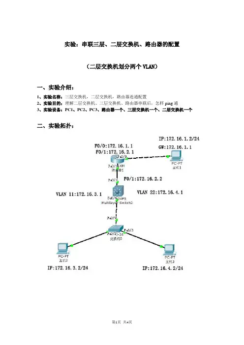
实验:串联三层、二层交换机、路由器的配置(二层交换机划分两个VLAN)一、实验介绍:1、实验名称:三层交换机,二层交换机,路由器连通配置2、实验目的:理解二层交换机、三层交换机、路由器串联后,怎样ping通3、实验设备:PC1、PC2、PC3、路由器一个、三层交换机一个、二层交换机一个二、实验拓扑:三、实验步骤1.PC1和路由器的配置:A.PCI配置IP ,:172.16.1.2 掩码:255.255.255.0 网关:172.16.1.1验证:c:\>ipconfigB.路由器F0/0 IP:172.16.1.1 掩码:255.255.255.0F0/1 IP:172.16.2.1 掩码:255.255.255.0>enable 进入特权模式# configure terminal 进入全局模式(config)# interface fastethernet 0/0 进入以太网fa 0/0配置模式(config-if)# ip address 172.16.1.1 255.255.255.0 配置以太网接口0 IP地址、掩码(config-if)# no shutdown 开启端口(config-if)# exit 退回全局模式(config)# interface fastethernet 0/1 进入以太网fa 0/1配置模式(config-if)# ip address 172.16.2.1 255.255.255.0 配置以太网接口1 IP地址、掩码(config-if)# no shutdown 开启端口验证方法:# show running-config 或#show interface serial 2(config-if)# exit 退回全局模式(config)# ip toute 172.16.3.0 255.255.255.0 172.16.2.2 配置3 号网段静态路由(config)# ip toute 172.16.4.0 255.255.255.0 172.16.2.2 配置4 号网段静态路由验证方法:特权模式下打show ip route# write 保存配置2.三层交换机的配置:A.F0/1端口配置IP:172.16.2.2 掩码:255.255.255.0创建VLAN 11 VLAN 22 配置IP:VLAN 11 :172.16.3.1 vlan 22 :172.16.4.1>enable 进入特权模式# configure terminal 进入全局模式(config)# interface fastethernet 0/1 进入以太网fa 0/1配置模式(config-if)# no switchport 端口开启三层交换(config-if)# ip address 172.16.2.2 255.255.255.0 为端口配置IP(config-if)# no shutdown 开启端口(config-if)# exit 退回全局模式(config)# vlan 22 创建vlan 22(config)# vlan 33 创建vlan 33验证:特权模式下打show vlan(config-if)# exit 退回全局模式(config)# interface vlan 22 进入vlan 22 配置模式(config-if)# ip address 172.16.3.1 255.255.255.0 配置vlan 22的IP(config-if)# no shutdown 激活(config)# interface vlan 33 进入vlan 33 配置模式(config-if)# ip address 172.16.4.1 255.255.255.0 配置vlan 33的IP(config-if)# no shutdown 激活(config-if)# exit 退回全局配置模式(config)# ip route 172.16.1.0 255.255.255.0 172.16.2.1 添加1 号网段静态路由(config)# interface fastethernet 0/4 进入以太网fa 0/4配置模式(config-if)# switchport mode trunk 设置为干道# write 保存配置验证:# show running-config 或#show interface serial 2路由验证:show ip route3.二层交换机,PC2,PC3的配置:A.二层交换机划分两个vlanB.P C2 IP:172.16.3.2 掩码:255.255.255.0PC2 IP:172.16.4.2 掩码:255.255.255.0二层交换机配置>enable 进入特权模式# configure terminal 进入全局模式(config)# vlan 22 创建vlan 22(config)# vlan 33 创建vlan 33(config)# interface fastethernet 0/2 进入2端口配置模式(config-if)# switchport access vlan 22 将2 端口加入vlan 22(config-if)# exit 退回全局配置模式(config)# interface fastethernet 0/3 进入3端口配置模式(config-if)# switchport access vlan 33 将3 端口加入vlan 33config-if)# exit 退回全局模式(config)# interface fastethernet 0/4 进入4端口配置模式(config-if)# switchport mode trunk 设置为干道# write 保存配置验证:show vlanPC配置A.PC2 IP:172.16.3.2 掩码:255.255.255.0 网关:172.16.3.1 B.PC2 IP:172.16.4.2 掩码:255.255.255.0 网关:172.16.4.14.测试:PCI ping 172.16.1.1 172.16.2.1 172.16.2.2172.16.3.1172.16.4.1172.16.3.2 172.16.4.2PC2 Ping 172.16.3.1 172.16.4.1 172.16.4.2172.16.2.2172.16.2.1172.16.1.1 172.16.1.2PC3 ping 172.16.4.1 172.16.3.1 172.16.3.2172.16.2.2 172.16.2.1172.16.1.1 172.16.1.2。
第1篇一、实验目的本次实验旨在使学生了解和掌握网络配置的基本方法,熟悉网络设备的操作,并能根据实际需求设计简单的网络拓扑结构。
通过实验,学生应能够:1. 熟悉网络设备的操作界面和基本功能。
2. 掌握IP地址的配置方法。
3. 理解子网划分和VLAN的设置。
4. 学会网络路由协议的配置。
5. 了解网络安全的配置方法。
二、实验环境1. 实验设备:一台PC机、一台路由器、一台交换机。
2. 软件环境:Windows操作系统、Packet Tracer 7.3.1模拟器。
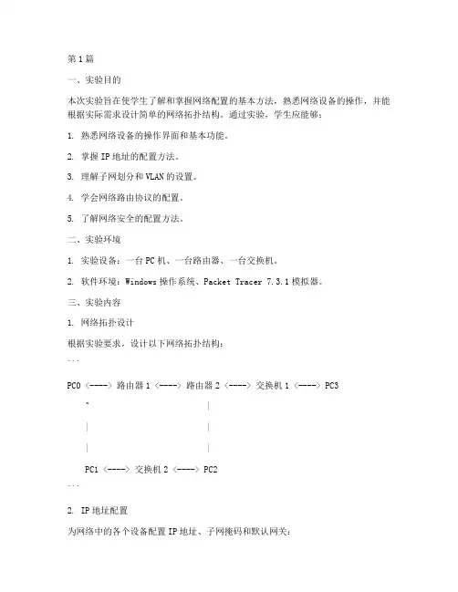
三、实验内容1. 网络拓扑设计根据实验要求,设计以下网络拓扑结构:```PC0 <----> 路由器1 <----> 路由器2 <----> 交换机1 <----> PC3^ || || |PC1 <----> 交换机2 <----> PC2```2. IP地址配置为网络中的各个设备配置IP地址、子网掩码和默认网关:- PC0: IP地址 192.168.1.1,子网掩码 255.255.255.0,默认网关 192.168.1.2- 路由器1: 接口1: IP地址 192.168.1.2,子网掩码 255.255.255.0,接口2: IP地址 192.168.2.1,子网掩码 255.255.255.0- 路由器2: 接口1: IP地址 192.168.2.2,子网掩码 255.255.255.0,接口2: IP地址 192.168.3.1,子网掩码 255.255.255.0- 交换机1: 接口1: IP地址 192.168.1.3,子网掩码 255.255.255.0,接口2: IP地址 192.168.2.2,子网掩码 255.255.255.0- PC1: IP地址 192.168.2.2,子网掩码 255.255.255.0,默认网关 192.168.2.1 - PC2: IP地址 192.168.3.2,子网掩码 255.255.255.0,默认网关 192.168.3.1 - PC3: IP地址 192.168.3.3,子网掩码 255.255.255.0,默认网关 192.168.3.1 3. VLAN配置为交换机设置VLAN,并将端口划分到对应的VLAN:- 交换机1: VLAN 10: 接口1,VLAN 20: 接口2- 交换机2: VLAN 10: 接口1,VLAN 20: 接口24. 路由协议配置为路由器配置静态路由和RIP协议:- 路由器1: 静态路由 192.168.3.0/24 下一跳 192.168.2.2- 路由器2: 静态路由 192.168.1.0/24 下一跳 192.168.2.1,RIP协议5. 网络安全配置为路由器配置访问控制列表(ACL):- 路由器1: ACL 100 deny ip any any- 路由器2: ACL 100 deny ip any any四、实验步骤1. 在Packet Tracer中搭建网络拓扑结构。

交换机、路由器综合实验(三)一、实验目的:掌握较复杂网络的交换机和路由器的配置问题。
二、实验环境:Cisco路由器3台;Catalyst 3550交换机1台;PC机3台。
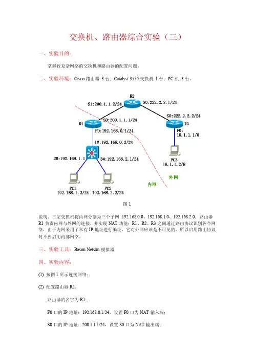
图1说明:三层交换机将内网分割为三个子网192.168.0.0、192.168.1.0、192.168.2.0;路由器R1负责内网与外网的连接,并实现NAT功能;R1、R2、R3之间通过路由协议识别各个网络,由于内网采用了私有IP地址进行编址,它对外网应该是不可见的,所以启用路由协议时不要启用内部网络。
三、实验工具:Boson Netsim模拟器四、实验内容:(1) 按图1所示连接网络;(2) 配置路由器R1:路由器的名字为R1;F0口的IP地址:192.168.0.1/24,设置F0口为NAT输入端;S0口的IP地址:200.1.1.1/24,设置S0口为NAT输出端;配置NAT池,地址范围为200.1.1.10~200.1.1.20,将内网中格式为192.168.*.* 的IP 地址转换为NAT池中的IP地址;配置静态路由,将目的网络为192.168.1.0 或192.168.2.0 的数据报发往192.168.0.2;配置OSPF路由协议,区域号为10,在它的外网地址上启用协议。
(3) 配置路由器R2:路由器的名字为R2;S0口的IP地址:222.2.2.1/24;S1口的IP地址:200.1.1.2/24;配置OSPF路由协议,区域号为10,在它的所有直连网络上启用协议。
(4) 配置路由器R3:路由器的名字为R3;F0口的IP地址:18.1.1.1/8;S0口的IP地址:222.2.2.2/24;配置OSPF路由协议,区域号为10,在它的所有直连网络上启用协议。
(5) 配置三层交换机:把F0/1口设置为三层路由口,IP地址为192.168.0.2/24;把F0/2口设置为三层路由口,IP地址为192.168.1.1/24;把F0/3口设置为三层路由口,IP地址为192.168.2.1/24;配置默认路由,方向为R1路由器的F0口;启用路由功能。
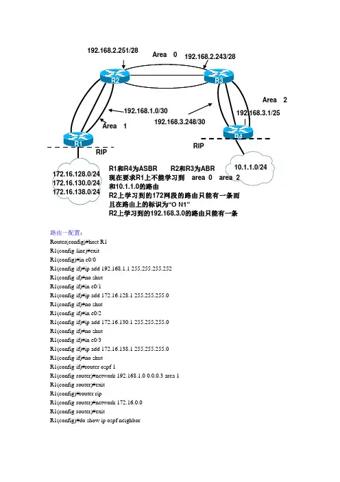
路由一配置:Router(config)#host R1R1(config-line)#exitR1(config)#in e0/0R1(config-if)#ip add 192.168.1.1 255.255.255.252R1(config-if)#no shutR1(config-if)#in e0/1R1(config-if)#ip add 172.16.128.1 255.255.255.0R1(config-if)#no shutR1(config-if)#in e0/2R1(config-if)#ip add 172.16.130.1 255.255.255.0R1(config-if)#no shutR1(config-if)#in e0/3R1(config-if)#ip add 172.16.138.1 255.255.255.0R1(config-if)#no shutR1(config-if)#router ospf 1R1(config-router)#network 192.168.1.0 0.0.0.3 area 1R1(config-router)#exitR1(config)#router ripR1(config-router)#network 172.16.0.0R1(config-router)#exitR1(config)#do show ip ospf neighbor2192.168.2.251/28 R2上学习到的192.168.3.0的路由只能有一条Neighbor ID Pri State Dead Time Address Interface 192.168.2.251 1 FULL/DR 00:00:36 192.168.1.2 Ethernet0/0 R1(config)#do show ip routeCodes: C - connected, S - static, R - RIP, M - mobile, B - BGPD - EIGRP, EX - EIGRP external, O - OSPF, IA - OSPF inter areaN1 - OSPF NSSA external type 1, N2 - OSPF NSSA external type 2E1 - OSPF external type 1, E2 - OSPF external type 2i - IS-IS, su - IS-IS summary, L1 - IS-IS level-1, L2 - IS-IS level-2ia - IS-IS inter area, * - candidate default, U - per-user static routeo - ODR, P - periodic downloaded static routeGateway of last resort is not set172.16.0.0/24 is subnetted, 3 subnetsC 172.16.138.0 is directly connected, Ethernet0/3C 172.16.128.0 is directly connected, Ethernet0/1C 172.16.130.0 is directly connected, Ethernet0/2192.168.1.0/30 is subnetted, 1 subnetsC 192.168.1.0 is directly connected, Ethernet0/0192.168.2.0/28 is subnetted, 1 subnetsO IA 192.168.2.240 [110/20] via 192.168.1.2, 00:01:33, Ethernet0/0192.168.3.0/24 is variably subnetted, 2 subnets, 2 masksO IA 192.168.3.0/25 [110/40] via 192.168.1.2, 00:01:09, Ethernet0/0O IA 192.168.3.248/30 [110/30] via 192.168.1.2, 00:01:23, Ethernet0/0R1(config)#router ospf 1R1(config-router)#redistribute rip subnets metric 30 metric-type 1R1(config-router)#exitR1(config)#router ripR1(config-router)#redistribute ospf 1 metric 2R1(config-router)#passive-interface e0/0R1(config-router)#exitR1(config)#do show ip routeCodes: C - connected, S - static, R - RIP, M - mobile, B - BGPD - EIGRP, EX - EIGRP external, O - OSPF, IA - OSPF inter areaN1 - OSPF NSSA external type 1, N2 - OSPF NSSA external type 2E1 - OSPF external type 1, E2 - OSPF external type 2i - IS-IS, su - IS-IS summary, L1 - IS-IS level-1, L2 - IS-IS level-2ia - IS-IS inter area, * - candidate default, U - per-user static routeo - ODR, P - periodic downloaded static routeGateway of last resort is not set172.16.0.0/24 is subnetted, 3 subnetsC 172.16.138.0 is directly connected, Ethernet0/3C 172.16.128.0 is directly connected, Ethernet0/1C 172.16.130.0 is directly connected, Ethernet0/210.0.0.0/24 is subnetted, 1 subnetsO E1 10.1.1.0 [110/60] via 192.168.1.2, 00:01:38, Ethernet0/0 192.168.1.0/30 is subnetted, 1 subnetsC 192.168.1.0 is directly connected, Ethernet0/0192.168.2.0/28 is subnetted, 1 subnetsO IA 192.168.2.240 [110/20] via 192.168.1.2, 00:03:35, Ethernet0/0 192.168.3.0/24 is variably subnetted, 2 subnets, 2 masksO IA 192.168.3.0/25 [110/40] via 192.168.1.2, 00:03:35, Ethernet0/0O IA 192.168.3.248/30 [110/30] via 192.168.1.2, 00:03:35, Ethernet0/0 R1(config)#do ping 10.1.1.1 source 172.16.130.1Type escape sequence to abort.Sending 5, 100-byte ICMP Echos to 10.1.1.1, timeout is 2 seconds:Packet sent with a source address of 172.16.130.1Success rate is 100 percent (5/5), round-trip min/avg/max = 96/172/300 ms R1(config)#router ospf 1R1(config-router)#area 1 nssaR1(config-router)#summary-address 172.16.128.0 255.255.240.0R1(config-router)#do show ip routeCodes: C - connected, S - static, R - RIP, M - mobile, B - BGPD - EIGRP, EX - EIGRP external, O - OSPF, IA - OSPF inter areaN1 - OSPF NSSA external type 1, N2 - OSPF NSSA external type 2E1 - OSPF external type 1, E2 - OSPF external type 2i - IS-IS, su - IS-IS summary, L1 - IS-IS level-1, L2 - IS-IS level-2ia - IS-IS inter area, * - candidate default, U - per-user static routeo - ODR, P - periodic downloaded static routeGateway of last resort is 192.168.1.2 to network 0.0.0.0172.16.0.0/16 is variably subnetted, 4 subnets, 2 masksC 172.16.138.0/24 is directly connected, Ethernet0/3C 172.16.128.0/24 is directly connected, Ethernet0/1O 172.16.128.0/20 is a summary, 00:01:04, Null0C 172.16.130.0/24 is directly connected, Ethernet0/2192.168.1.0/30 is subnetted, 1 subnetsC 192.168.1.0 is directly connected, Ethernet0/0O*IA 0.0.0.0/0 [110/11] via 192.168.1.2, 00:02:55, Ethernet0/0注:只有在重发布以后才可运行NSSA,NSSA的配置必须是双向的路由二配置:Router(config)#host R2R2(config)#in e0/0R2(config-if)#ip add 192.168.1.2 255.255.255.252R2(config-if)#no shutR2(config-if)#in e0/1R2(config-if)#ip add 192.168.2.251 255.255.255.240R2(config-if)#no shutR2(config-if)#router ospf 1R2(config-router)#network 192.168.2.240 0.0.0.15 area 0R2(config-router)#network 192.168.1.0 0.0.0.3 area 1R2(config-router)#exitR2(config)#do show ip ospf neighborNeighbor ID Pri State Dead Time Address Interface 192.168.3.249 1 FULL/DR 00:00:37 192.168.2.243 Ethernet0/1 192.168.1.1 1 FULL/BDR 00:00:31 192.168.1.1 Ethernet0/0 R2(config)#do show ip routeCodes: C - connected, S - static, R - RIP, M - mobile, B - BGPD - EIGRP, EX - EIGRP external, O - OSPF, IA - OSPF inter areaN1 - OSPF NSSA external type 1, N2 - OSPF NSSA external type 2E1 - OSPF external type 1, E2 - OSPF external type 2i - IS-IS, su - IS-IS summary, L1 - IS-IS level-1, L2 - IS-IS level-2ia - IS-IS inter area, * - candidate default, U - per-user static routeo - ODR, P - periodic downloaded static routeGateway of last resort is not set192.168.1.0/30 is subnetted, 1 subnetsC 192.168.1.0 is directly connected, Ethernet0/0192.168.2.0/28 is subnetted, 1 subnetsC 192.168.2.240 is directly connected, Ethernet0/1192.168.3.0/24 is variably subnetted, 2 subnets, 2 masksO IA 192.168.3.0/25 [110/30] via 192.168.2.243, 00:01:22, Ethernet0/1O IA 192.168.3.248/30 [110/20] via 192.168.2.243, 00:01:37, Ethernet0/1R2(config)#do show ip routeCodes: C - connected, S - static, R - RIP, M - mobile, B - BGPD - EIGRP, EX - EIGRP external, O - OSPF, IA - OSPF inter areaN1 - OSPF NSSA external type 1, N2 - OSPF NSSA external type 2E1 - OSPF external type 1, E2 - OSPF external type 2i - IS-IS, su - IS-IS summary, L1 - IS-IS level-1, L2 - IS-IS level-2ia - IS-IS inter area, * - candidate default, U - per-user static routeo - ODR, P - periodic downloaded static routeGateway of last resort is not set172.16.0.0/24 is subnetted, 3 subnetsO E1 172.16.138.0 [110/40] via 192.168.1.1, 00:01:48, Ethernet0/0O E1 172.16.128.0 [110/40] via 192.168.1.1, 00:01:48, Ethernet0/0O E1 172.16.130.0 [110/40] via 192.168.1.1, 00:01:48, Ethernet0/010.0.0.0/24 is subnetted, 1 subnetsO E1 10.1.1.0 [110/50] via 192.168.2.243, 00:01:48, Ethernet0/1 192.168.1.0/30 is subnetted, 1 subnetsC 192.168.1.0 is directly connected, Ethernet0/0192.168.2.0/28 is subnetted, 1 subnetsC 192.168.2.240 is directly connected, Ethernet0/1192.168.3.0/24 is variably subnetted, 2 subnets, 2 masksO IA 192.168.3.0/25 [110/30] via 192.168.2.243, 00:03:45, Ethernet0/1 O IA 192.168.3.248/30 [110/20] via 192.168.2.243, 00:03:45, Ethernet0/1 R2(config)#router ospf 1R2(config-router)#area 1 nssa no-summaryR2(config-router)#do show ip routeCodes: C - connected, S - static, R - RIP, M - mobile, B - BGPD - EIGRP, EX - EIGRP external, O - OSPF, IA - OSPF inter areaN1 - OSPF NSSA external type 1, N2 - OSPF NSSA external type 2E1 - OSPF external type 1, E2 - OSPF external type 2i - IS-IS, su - IS-IS summary, L1 - IS-IS level-1, L2 - IS-IS level-2ia - IS-IS inter area, * - candidate default, U - per-user static routeo - ODR, P - periodic downloaded static routeGateway of last resort is not set172.16.0.0/20 is subnetted, 1 subnetsO N1 172.16.128.0 [110/40] via 192.168.1.1, 00:01:09, Ethernet0/010.0.0.0/24 is subnetted, 1 subnetsO E1 10.1.1.0 [110/50] via 192.168.2.243, 00:01:09, Ethernet0/1 192.168.1.0/30 is subnetted, 1 subnetsC 192.168.1.0 is directly connected, Ethernet0/0192.168.2.0/28 is subnetted, 1 subnetsC 192.168.2.240 is directly connected, Ethernet0/1O IA 192.168.3.0/24 [110/20] via 192.168.2.243, 00:01:14, Ethernet0/1路由三配置:Router(config)#host R3R3(config)#in e0/1R3(config-if)#ip add 192.168.2.243 255.255.255.240R3(config-if)#no shutR3(config-if)#in e0/2R3(config-if)#ip add 192.168.3.249 255.255.255.252R3(config-if)#no shutR3(config-if)#router ospf 1R3(config-router)#network 192.168.3.248 0.0.0.3 area 2R3(config-router)#network 192.168.2.240 0.0.0.15 area 0R3(config-router)#do show ip ospf neighborNeighbor ID Pri State Dead Time Address Interface 192.168.2.251 1 FULL/DR 00:00:32 192.168.2.251 Ethernet0/1 192.168.3.250 1 FULL/BDR 00:00:36 192.168.3.250 Ethernet0/2 R3(config-router)#do show ip routeCodes: C - connected, S - static, R - RIP, M - mobile, B - BGPD - EIGRP, EX - EIGRP external, O - OSPF, IA - OSPF inter areaN1 - OSPF NSSA external type 1, N2 - OSPF NSSA external type 2E1 - OSPF external type 1, E2 - OSPF external type 2i - IS-IS, su - IS-IS summary, L1 - IS-IS level-1, L2 - IS-IS level-2ia - IS-IS inter area, * - candidate default, U - per-user static routeo - ODR, P - periodic downloaded static routeGateway of last resort is not set192.168.1.0/30 is subnetted, 1 subnetsO IA 192.168.1.0 [110/20] via 192.168.2.251, 00:01:31, Ethernet0/1192.168.2.0/28 is subnetted, 1 subnetsC 192.168.2.240 is directly connected, Ethernet0/1192.168.3.0/24 is variably subnetted, 2 subnets, 2 masksO 192.168.3.0/25 [110/20] via 192.168.3.250, 00:01:31, Ethernet0/2C 192.168.3.248/30 is directly connected, Ethernet0/2R3(config-router)#do show ip routeCodes: C - connected, S - static, R - RIP, M - mobile, B - BGPD - EIGRP, EX - EIGRP external, O - OSPF, IA - OSPF inter areaN1 - OSPF NSSA external type 1, N2 - OSPF NSSA external type 2E1 - OSPF external type 1, E2 - OSPF external type 2i - IS-IS, su - IS-IS summary, L1 - IS-IS level-1, L2 - IS-IS level-2ia - IS-IS inter area, * - candidate default, U - per-user static routeo - ODR, P - periodic downloaded static routeGateway of last resort is not set172.16.0.0/24 is subnetted, 3 subnetsO E1 172.16.138.0 [110/50] via 192.168.2.251, 00:02:01, Ethernet0/1O E1 172.16.128.0 [110/50] via 192.168.2.251, 00:02:01, Ethernet0/1O E1 172.16.130.0 [110/50] via 192.168.2.251, 00:02:01, Ethernet0/110.0.0.0/24 is subnetted, 1 subnetsO E1 10.1.1.0 [110/40] via 192.168.3.250, 00:02:01, Ethernet0/2192.168.1.0/30 is subnetted, 1 subnetsO IA 192.168.1.0 [110/20] via 192.168.2.251, 00:02:01, Ethernet0/1 192.168.2.0/28 is subnetted, 1 subnetsC 192.168.2.240 is directly connected, Ethernet0/1192.168.3.0/24 is variably subnetted, 2 subnets, 2 masksO 192.168.3.0/25 [110/20] via 192.168.3.250, 00:02:01, Ethernet0/2 C 192.168.3.248/30 is directly connected, Ethernet0/2R3(config-router)#area 2 nssa no-summaryR3(config-router)#area 2 range 192.168.3.0 255.255.255.0R3(config-router)#do show ip routeCodes: C - connected, S - static, R - RIP, M - mobile, B - BGPD - EIGRP, EX - EIGRP external, O - OSPF, IA - OSPF inter areaN1 - OSPF NSSA external type 1, N2 - OSPF NSSA external type 2E1 - OSPF external type 1, E2 - OSPF external type 2i - IS-IS, su - IS-IS summary, L1 - IS-IS level-1, L2 - IS-IS level-2ia - IS-IS inter area, * - candidate default, U - per-user static routeo - ODR, P - periodic downloaded static routeGateway of last resort is not set172.16.0.0/20 is subnetted, 1 subnetsO E1 172.16.128.0 [110/50] via 192.168.2.251, 00:03:59, Ethernet0/110.0.0.0/24 is subnetted, 1 subnetsO N1 10.1.1.0 [110/50] via 192.168.3.250, 00:03:59, Ethernet0/2 192.168.1.0/30 is subnetted, 1 subnetsO IA 192.168.1.0 [110/20] via 192.168.2.251, 00:03:59, Ethernet0/1 192.168.2.0/28 is subnetted, 1 subnetsC 192.168.2.240 is directly connected, Ethernet0/1192.168.3.0/24 is variably subnetted, 3 subnets, 3 masksO 192.168.3.0/25 [110/20] via 192.168.3.250, 00:03:59, Ethernet0/2 O 192.168.3.0/24 is a summary, 00:03:59, Null0C 192.168.3.248/30 is directly connected, Ethernet0/2路由四配置:Router(config)#host R4R4(config)#in e0/2R4(config-if)#ip add 192.168.3.250 255.255.255.252R4(config-if)#no shutR4(config-if)#in e0/1R4(config-if)#ip add 192.168.3.1 255.255.255.128R4(config-if)#no shutR4(config-if)#in e0/0R4(config-if)#ip add 10.1.1.1 255.255.255.0R4(config-if)#no shutR4(config-if)#router ospf 1R4(config-router)#network 192.168.3.248 0.0.0.3 area 2R4(config-router)#network 192.168.3.0 0.0.0.127 area 2R4(config-router)#exitR4(config)#router ripR4(config-router)#network 10.0.0.0R4(config-router)#exitR4(config)#do show ip ospf neighborNeighbor ID Pri State Dead Time Address Interface 192.168.3.249 1 FULL/BDR 00:00:36 192.168.3.249 Ethernet0/2 R4(config)#do show ip routeCodes: C - connected, S - static, R - RIP, M - mobile, B - BGPD - EIGRP, EX - EIGRP external, O - OSPF, IA - OSPF inter areaN1 - OSPF NSSA external type 1, N2 - OSPF NSSA external type 2E1 - OSPF external type 1, E2 - OSPF external type 2i - IS-IS, su - IS-IS summary, L1 - IS-IS level-1, L2 - IS-IS level-2ia - IS-IS inter area, * - candidate default, U - per-user static routeo - ODR, P - periodic downloaded static routeGateway of last resort is not set10.0.0.0/24 is subnetted, 1 subnetsC 10.1.1.0 is directly connected, Ethernet0/0192.168.1.0/30 is subnetted, 1 subnetsO IA 192.168.1.0 [110/30] via 192.168.3.249, 00:01:36, Ethernet0/2192.168.2.0/28 is subnetted, 1 subnetsO IA 192.168.2.240 [110/20] via 192.168.3.249, 00:01:36, Ethernet0/2 192.168.3.0/24 is variably subnetted, 2 subnets, 2 masksC 192.168.3.0/25 is directly connected, Ethernet0/1C 192.168.3.248/30 is directly connected, Ethernet0/2R4(config)#router ospf 1R4(config-router)#redistribute rip subnets metric 30 metric-type 1R4(config-router)#exitR4(config)#router ripR4(config-router)#redistribute ospf 1 metric 2R4(config-router)#passive-interface e0/2R4(config-router)#exitR4(config)#do show ip routeCodes: C - connected, S - static, R - RIP, M - mobile, B - BGPD - EIGRP, EX - EIGRP external, O - OSPF, IA - OSPF inter areaN1 - OSPF NSSA external type 1, N2 - OSPF NSSA external type 2E1 - OSPF external type 1, E2 - OSPF external type 2i - IS-IS, su - IS-IS summary, L1 - IS-IS level-1, L2 - IS-IS level-2ia - IS-IS inter area, * - candidate default, U - per-user static routeo - ODR, P - periodic downloaded static routeGateway of last resort is not set172.16.0.0/24 is subnetted, 3 subnetsO E1 172.16.138.0 [110/60] via 192.168.3.249, 00:01:19, Ethernet0/2O E1 172.16.128.0 [110/60] via 192.168.3.249, 00:01:19, Ethernet0/2O E1 172.16.130.0 [110/60] via 192.168.3.249, 00:01:19, Ethernet0/210.0.0.0/24 is subnetted, 1 subnetsC 10.1.1.0 is directly connected, Ethernet0/0192.168.1.0/30 is subnetted, 1 subnetsO IA 192.168.1.0 [110/30] via 192.168.3.249, 00:01:19, Ethernet0/2 192.168.2.0/28 is subnetted, 1 subnetsO IA 192.168.2.240 [110/20] via 192.168.3.249, 00:01:19, Ethernet0/2 192.168.3.0/24 is variably subnetted, 2 subnets, 2 masksC 192.168.3.0/25 is directly connected, Ethernet0/1C 192.168.3.248/30 is directly connected, Ethernet0/2R4(config)#do ping 172.16.138.1 source 10.1.1.1Type escape sequence to abort.Sending 5, 100-byte ICMP Echos to 172.16.138.1, timeout is 2 seconds: Packet sent with a source address of 10.1.1.1Success rate is 100 percent (5/5), round-trip min/avg/max = 96/168/260 ms R4(config)#router ospf 1R4(config-router)#area 2 nssa no-summaryR4(config-router)#do show ip routeCodes: C - connected, S - static, R - RIP, M - mobile, B - BGPD - EIGRP, EX - EIGRP external, O - OSPF, IA - OSPF inter areaN1 - OSPF NSSA external type 1, N2 - OSPF NSSA external type 2E1 - OSPF external type 1, E2 - OSPF external type 2i - IS-IS, su - IS-IS summary, L1 - IS-IS level-1, L2 - IS-IS level-2ia - IS-IS inter area, * - candidate default, U - per-user static routeo - ODR, P - periodic downloaded static routeGateway of last resort is 192.168.3.249 to network 0.0.0.010.0.0.0/24 is subnetted, 1 subnetsC 10.1.1.0 is directly connected, Ethernet0/0192.168.3.0/24 is variably subnetted, 2 subnets, 2 masksC 192.168.3.0/25 is directly connected, Ethernet0/1C 192.168.3.248/30 is directly connected, Ethernet0/2O*IA 0.0.0.0/0 [110/11] via 192.168.3.249, 00:05:56, Ethernet0/2R4(config-router)#do ping 172.16.130.1 source 10.1.1.1Type escape sequence to abort.Sending 5, 100-byte ICMP Echos to 172.16.130.1, timeout is 2 seconds:Packet sent with a source address of 10.1.1.1Success rate is 100 percent (5/5), round-trip min/avg/max = 100/193/312 ms实验步骤总结:R1 1、OSPF ,RIP 2、查看邻接关系3、重发布4、完全NSSA5、地址汇总R2 1、OSPF 2、查看邻接关系3、完全NSSAR3 1、OSPF 2、查看邻接关系3、完全NSSA 4、地址汇总R4 1、OSPF ,RIP 2、查看邻接关系3、重发布4、完全NSSA。

三层交换实验报告三层交换实验报告一、实验目的本次实验的目的是通过搭建一个三层交换网络,探究其在数据传输中的优势和应用场景。
通过实验,我们将深入了解三层交换的工作原理、配置方法以及网络性能的提升。
二、实验环境本次实验所使用的设备包括三层交换机、路由器和PC机。
三层交换机采用了Cisco的Catalyst系列,路由器采用了Cisco的ISR系列。
PC机作为终端设备,用于发送和接收数据。
三、实验过程1. 配置三层交换机首先,我们需要在三层交换机上进行基本配置。
通过命令行界面,我们可以设置交换机的IP地址、子网掩码和默认网关。
这样,交换机就能够与其他设备进行通信。
2. 配置路由器接下来,我们需要在路由器上进行配置。
通过命令行界面,我们可以设置路由器的IP地址、子网掩码和默认网关。
此外,我们还需要配置路由表,以便路由器能够正确地转发数据包。
3. 连接设备在完成配置后,我们需要将三层交换机、路由器和PC机进行连接。
通过使用网线将它们连接起来,我们可以建立一个局域网。
在局域网中,三层交换机负责交换数据包,路由器负责转发数据包,PC机作为终端设备进行数据的发送和接收。
4. 测试网络性能在搭建好网络之后,我们可以进行性能测试。
通过发送大量的数据包,我们可以测试网络的吞吐量和延迟。
三层交换机的优势在于它能够根据目的IP地址来转发数据包,从而提高网络的传输效率。
而传统的二层交换机只能根据MAC 地址来转发数据包,效率较低。
四、实验结果经过测试,我们发现三层交换机在数据传输中的确具有一定的优势。
相比于传统的二层交换机,三层交换机能够更快地转发数据包,从而提高了网络的传输效率。
此外,三层交换机还支持更多的网络协议,可以满足更多的应用需求。
五、实验总结通过本次实验,我们深入了解了三层交换的工作原理和配置方法。
三层交换机在现代网络中扮演着重要的角色,它能够提高网络的传输效率和性能。
在实际应用中,我们可以将三层交换机应用于大型企业网络、数据中心等场景,以满足高速、大容量的数据传输需求。
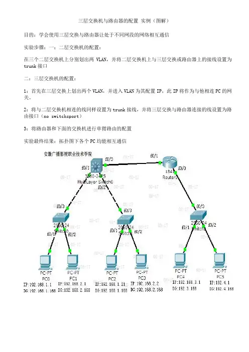
三层交换机与路由器的配置实例(图解)目的:学会使用三层交换与路由器让处于不同网段的网络相互通信实验步骤:一:二层交换机的配置:在三个二层交换机上分别划出两VLAN,并将二层交换机上与三层交换或路由器上的接线设置为trunk接口二:三层交换机的配置:1:首先在三层交换上划出两个VLAN,并进入VLAN为其配置IP,此IP将作为与他相连PC的网关。
2:将与二层交换机相连的线同样设置为trunk接线,并将三层交换与路由器连接的线设置为路由接口(no switchsport)3:将路由器和下面的交换机进行单臂路由的配置实验最终结果:拓扑图下各个PC均能相互通信交换机的配置命令:SW 0:Switch>Switch>enSwitch#confConfiguring from terminal, memory, or network [terminal]?Enter configuration commands, one per line. End with CNTL/Z.Switch(config)#vlan 2Switch(config-vlan)#exitSwitch(config)#int f0/2Switch(config-if)#switchport access vlan 2Switch(config-if)#no shutSwitch(config-if)#int f0/3Switch(config-if)#switchport mode trunk%LINEPROTO-5-UPDOWN: Line protocol on Interface FastEthernet0/3, changed state to down %LINEPROTO-5-UPDOWN: Line protocol on Interface FastEthernet0/3, changed state to up Switch(config-if)#exitSwitch(config)#SW 1:Switch>enSwitch#confConfiguring from terminal, memory, or network [terminal]?Enter configuration commands, one per line. End with CNTL/Z.Switch(config)#int f0/2Switch(config-if)#switchport access vlan 2% Access VLAN does not exist. Creating vlan 2Switch(config-if)#no shutSwitch(config-if)#exitSwitch(config)#int f0/3Switch(config-if)#switchport mode trunk%LINEPROTO-5-UPDOWN: Line protocol on Interface FastEthernet0/3, changed state to down %LINEPROTO-5-UPDOWN: Line protocol on Interface FastEthernet0/3, changed state to up Switch(config-if)#SW 2:Switch>enSwitch#confConfiguring from terminal, memory, or network [terminal]?Enter configuration commands, one per line. End with CNTL/Z.Switch(config-if)#switchport access vlan 2% Access VLAN does not exist. Creating vlan 2Switch(config-if)#exitSwitch(config)#int f0/3Switch(config-if)#switchport mode trunkSwitch(config-if)#三层交换的配置命令:Switch>enSwitch#confConfiguring from terminal, memory, or network [terminal]?Enter configuration commands, one per line. End with CNTL/Z.Switch(config)#int f0/1Switch(config-if)#switchport mode trunk%LINEPROTO-5-UPDOWN: Line protocol on Interface FastEthernet0/2, changed state to down Switch(config-if)#exitSwitch(config)#int f0/2Switch(config-if)#switchport mode trunkSwitch(config-if)#exitSwitch(config)#vlan 2Switch(config-vlan)#exitSwitch(config)#int vlan 1Switch(config-if)#no shut%LINK-5-CHANGED: Interface Vlan1, changed state to up%LINEPROTO-5-UPDOWN: Line protocol on Interface Vlan1, changed state to upSwitch(config-if)#ip address 192.168.1.168 255.255.255.0Switch(config-if)#exitSwitch(config)#int vlan 2%LINK-5-CHANGED: Interface Vlan2, changed state to up%LINEPROTO-5-UPDOWN: Line protocol on Interface Vlan2, changed state to upSwitch(config-if)#ip addSwitch(config-if)#ip address 192.168.2.168 255.255.255.0Switch(config-if)#%LINK-5-CHANGED: Interface FastEthernet0/3, changed state to up%LINEPROTO-5-UPDOWN: Line protocol on Interface FastEthernet0/3, changed state to up Switch(config-if)#exitSwitch(config)#int f0/3Switch(config-if)#no switchport%LINEPROTO-5-UPDOWN: Line protocol on Interface FastEthernet0/3, changed state to down %LINEPROTO-5-UPDOWN: Line protocol on Interface FastEthernet0/3, changed state to upSwitch(config-if)#Switch(config-if)#ip address 192.168.10.1 255.255.255.0Switch(config-if)#exitSwitch(config)#ip routingSwitch(config-if)#exitSwitch(config)#ip route 0.0.0.0 0.0.0.0 192.168.10.2Switch(config)#路由器的配置:Router>enRouter#confConfiguring from terminal, memory, or network [terminal]?Enter configuration commands, one per line. End with CNTL/Z.Router(config)#int f0/0Router(config-if)#no shut%LINK-5-CHANGED: Interface FastEthernet0/0, changed state to upRouter(config-if)#exitRouter(config)#int f0/1Router(config-if)#no shut%LINK-5-CHANGED: Interface FastEthernet0/1, changed state to up%LINEPROTO-5-UPDOWN: Line protocol on Interface FastEthernet0/1, changed state to up Router(config-if)#exitRouter(config)#int f0/0Router(config-if)#no shutRouter(config-if)#exitRouter(config)#int f0/0.1Router(config-subif)#encapsulation dot1Q 1Router(config-subif)#ip address 192.168.3.168 255.255.255.0Router(config-subif)#exitRouter(config)#int f0/0.2Router(config-subif)#encapsulation dot1Q 2Router(config-subif)#ip addRouter(config-subif)#ip address 192.168.4.168 255.255.255.0Router(config-subif)#exitRouter(config)#ip route 0.0.0.0 0.0.0.0 192.168.10.1Router(config)#exit%SYS-5-CONFIG_I: Configured from console by consoleRouter#confConfiguring from terminal, memory, or network [terminal]?Enter configuration commands, one per line. End with CNTL/Z.Router(config)#int f0/1Router(config-if)#ip addRouter(config-if)#ip address 192.168.10.2 255.255.255.0Router(config-if)#我不知道为什么你要在三层交换机上把f0/1划入vlan 10、f0/2划入vlan 20 我觉得你这样做是完全多余的你试试去掉在SWA上配置的“把f0/1划入vlan 10、f0/2划入vlan 20”然后看看能否通信了我的配置是:三层交换机(就是你的SA):Switch>en //进入特权模式Switch#conf t //进入全局模式Switch(config)#in f0/24 //进入f0/24接口Switch(config-if)#sw mo tr //启用trunkSwitch#vlan da //进入vlan数据库模式Switch(vlan)#vlan 10 //创建valn 10Switch(vlan)#vlan 20 //创建valn 20Switch(vlan)#ex //退出vlan数据库模式Switch#conf tSwitch(config)#in vlan 10 //进入vlan 10Switch(config-if)#ip add 192.168.10.254 255.255.255.0 //配置IP Switch(config-if)#no sh //启用Switch(config-if)#ex //退出Switch(config)#in vlan 20Switch(config-if)#ip add 192.168.20.254 255.255.255.0Switch(config-if)#no sh二层交换(就是你的SB):Switch>enSwitch#conf tSwitch(config)#in f0/24Switch(config-if)#sw mo trSwitch#vlan daSwitch(vlan)#vlan 10Switch(vlan)#vlan 20Switch(vlan)#exSwitch#conf tSwitch(config)#in f0/23Switch(config-if)#sw acc vlan 10Switch(config-if)#sw mo accSwitch(config-if)#exSwitch(config)#in f0/22Switch(config-if)#sw acc vlan 10Switch(config-if)#sw mo accSwitch(config-if)#exSwitch(config)#in f0/21Switch(config-if)#sw acc vlan 20Switch(config-if)#sw mo accPC1:PC>ipconfigIP Address......................: 192.168.10.111Subnet Mask.....................: 255.255.255.0Default Gateway.................: 192.168.10.254PC2:PC>ipconfigIP Address......................: 192.168.10.222Subnet Mask.....................: 255.255.255.0Default Gateway.................: 192.168.10.254PC3:PC>ipconfigIP Address......................: 192.168.20.111Subnet Mask.....................: 255.255.255.0Default Gateway.................: 192.168.20.254经测试: pc1 ping pc3是通的任何一台PC都能PING通网关和其他PC设备:华为3928三层交换机一台,PC主机两台PC-A ,PC-B。
三层交换机路由功能配置实验总结三层交换机作为一种网络交换设备,除了基本的交换功能外,还具备了路由功能。
在网络中,路由功能是至关重要的,因为它可以实现不同子网之间的通信。
本文将介绍如何通过三层交换机实现路由功能,并进行实验总结。
一、实验环境本次实验环境如下:1. 三台计算机,分别连接在三个不同的子网中,IP地址分别为:- 192.168.1.2/24- 192.168.2.2/24- 192.168.3.2/242. 三层交换机,具备路由功能,连接以上三个子网。
二、实验步骤1. 配置三层交换机的接口IP地址三层交换机需要为每个接口分配IP地址,以便能够在不同的子网之间进行路由转发。
在本次实验中,我们需要为三个接口分别配置IP 地址:- 接口 VLAN 1:192.168.1.1/24- 接口 VLAN 2:192.168.2.1/24- 接口 VLAN 3:192.168.3.1/24可以通过以下命令进行配置:```interface vlan 1ip address 192.168.1.1 255.255.255.0no shutdowninterface vlan 2ip address 192.168.2.1 255.255.255.0no shutdowninterface vlan 3ip address 192.168.3.1 255.255.255.0no shutdown```2. 配置路由为了实现不同子网之间的通信,需要在三层交换机中配置路由。
在本次实验中,我们需要将两个子网之间的路由添加到路由表中。
假设需要从192.168.1.0/24子网中的计算机访问192.168.3.0/24子网中的计算机,需要将192.168.3.0/24子网的路由添加到路由表中。
可以通过以下命令进行配置:```ip route 192.168.3.0 255.255.255.0 192.168.2.2```其中,192.168.3.0 255.255.255.0表示需要访问的目标子网,192.168.2.2表示下一跳路由器的IP地址。
第1篇一、实验名称:网络设备调试与配置二、实验目的1. 熟悉网络设备的种类和功能。
2. 掌握网络设备的配置方法。
3. 学习网络故障排除的基本技能。
三、实验内容1. 网络设备种类及功能介绍2. 网络设备配置3. 网络故障排除四、实验器材1. 网络设备:路由器、交换机、网线等。
2. 计算机及操作系统:Windows、Linux等。
3. 网络调试工具:ping、tracert、netstat等。
五、实验步骤1. 网络设备种类及功能介绍(1)路由器:负责将数据包从源地址传输到目的地址,实现不同网络之间的互联。
(2)交换机:根据MAC地址转发数据帧,实现局域网内设备之间的通信。
(3)网线:用于连接网络设备,实现数据传输。
2. 网络设备配置(1)路由器配置1)连接路由器:将计算机通过网线连接到路由器的WAN口。
2)配置IP地址:在计算机上设置IP地址、子网掩码、默认网关等参数。
3)设置DHCP服务器:配置DHCP服务器,为局域网内设备自动分配IP地址。
4)配置NAT:设置NAT功能,实现局域网内设备访问公网。
(2)交换机配置1)连接交换机:将计算机通过网线连接到交换机。
2)配置VLAN:设置VLAN,实现不同VLAN之间的隔离。
3)配置端口安全:设置端口安全,防止未授权设备接入交换机。
3. 网络故障排除(1)使用ping命令测试网络连通性。
(2)使用tracert命令追踪数据包传输路径。
(3)使用netstat命令查看网络连接状态。
(4)根据故障现象,排除网络故障。
六、实验结果与分析1. 网络设备配置成功,计算机可以正常访问互联网。
2. 通过ping命令测试,局域网内设备之间可以互相通信。
3. 通过tracert命令追踪,数据包可以正常到达目的地址。
4. 通过netstat命令查看,网络连接状态正常。
七、实验总结1. 网络设备是计算机网络的重要组成部分,了解网络设备的种类和功能对网络维护和优化具有重要意义。
路由器交换机实验报告路由器交换机实验报告引言网络技术的快速发展使得人们对于网络设备的需求越来越高。
在现代网络中,路由器和交换机是两种常见的网络设备,它们在数据传输和网络连接方面起着重要的作用。
本实验报告将介绍路由器和交换机的基本原理、功能和应用,并通过实验验证它们在网络中的性能和效果。
一、路由器的原理和功能1.1 路由器的原理路由器是一种能够连接不同网络并进行数据传输的设备。
它通过将数据包从源地址发送到目标地址,实现网络之间的通信。
路由器根据路由表中的信息,选择最佳的路径将数据包转发到下一个网络节点,从而实现数据的传输。
1.2 路由器的功能路由器具有以下几个主要功能:- 路由选择:根据网络拓扑和路由表选择最佳路径进行数据传输。
- 数据转发:将数据包从一个网络节点转发到下一个网络节点。
- 分段和重组:将大数据包分割成小的数据段进行传输,并在目标地址处重新组装。
- 数据过滤和安全:根据配置的规则对数据包进行过滤和安全检查,保护网络的安全性。
- 网络地址转换(NAT):将私有IP地址转换为公共IP地址,实现内部网络与外部网络的通信。
二、交换机的原理和功能2.1 交换机的原理交换机是一种用于连接计算机和其他网络设备的网络设备。
它通过学习和存储MAC地址,并根据目标MAC地址将数据包转发到正确的端口,实现设备之间的直接通信。
交换机工作在数据链路层,通过建立和维护MAC地址表,实现数据的快速转发。
2.2 交换机的功能交换机具有以下几个主要功能:- 数据转发:通过学习和存储MAC地址,将数据包转发到正确的端口。
- 广播和组播:将数据包发送到所有连接的设备或者特定组内的设备。
- VLAN划分:将交换机划分为多个虚拟局域网,实现不同网络之间的隔离和管理。
- 链路聚合:将多个物理链路绑定为一个逻辑链路,提高带宽和可靠性。
- 交换机管理:通过配置交换机的参数和规则,管理和监控网络设备的状态和性能。
三、实验设计与结果分析为了验证路由器和交换机的性能和效果,我们进行了一系列实验。
一、实训背景随着互联网技术的飞速发展,网络设备在各个领域中的应用越来越广泛。
交换机和路由器作为网络通信的核心设备,其配置与管理对于网络性能和稳定性至关重要。
为了提高我们对网络设备的了解和实际操作能力,我们进行了为期两周的交换器路由器实训。
二、实训目标1. 掌握交换机和路由器的基本原理与功能。
2. 熟悉交换机和路由器的配置方法与步骤。
3. 学会使用网络设备进行网络拓扑规划与优化。
4. 培养团队合作与问题解决能力。
三、实训内容1. 交换机配置实训(1)交换机基本配置实训内容:完成交换机的启动、配置模式切换、基本配置(如IP地址、密码等)。
实训步骤:① 开启交换机电源,等待交换机自检完成。
② 通过控制台或SSH远程登录交换机。
③ 切换到全局配置模式。
④ 配置交换机名称、管理IP地址、登录密码等。
⑤ 保存配置。
(2)VLAN划分与配置实训内容:创建VLAN,配置VLAN接口,实现不同VLAN间的隔离。
实训步骤:① 切换到全局配置模式。
② 创建VLAN,如VLAN 10。
③ 配置VLAN接口,如接口FastEthernet0/1分配给VLAN 10。
④ 将VLAN 10下的端口分配给相应的用户。
⑤ 保存配置。
(3)STP配置实训内容:配置生成树协议(STP),防止网络环路。
实训步骤:① 切换到全局配置模式。
② 配置交换机优先级、根桥ID等STP参数。
③ 保存配置。
2. 路由器配置实训(1)路由器基本配置实训内容:完成路由器的启动、配置模式切换、基本配置(如IP地址、密码等)。
实训步骤:① 开启路由器电源,等待路由器自检完成。
② 通过控制台或SSH远程登录路由器。
③ 切换到全局配置模式。
④ 配置路由器名称、管理IP地址、登录密码等。
⑤ 保存配置。
(2)静态路由配置实训内容:配置静态路由,实现不同网络之间的互通。
实训步骤:① 切换到全局配置模式。
② 配置目的网络地址、下一跳路由器接口。
③ 保存配置。
(3)动态路由配置实训内容:配置动态路由协议(如RIP、OSPF等),实现路由器自动学习路由信息。
路由器交换机配置实验报告路由器交换机配置实验报告一、实验目的本次实验的目的是通过配置路由器和交换机,实现网络设备的互联和通信。
通过实际操作,掌握路由器和交换机的基本配置方法,并了解网络设备的工作原理和功能。
二、实验环境本次实验使用的设备包括一台路由器和两台交换机。
路由器用于连接不同的网络,实现不同网络之间的通信。
交换机用于连接多台计算机,实现内部局域网内的通信。
三、实验步骤1. 连接设备首先,将路由器和交换机通过网线连接起来。
将路由器的一个接口连接到交换机的一个接口,再将另一个交换机的接口连接到另一个接口。
确保连接正确无误。
2. 配置路由器进入路由器的配置界面,通过命令行输入用户名和密码进行登录。
登录成功后,进入路由器的配置模式。
3. 配置路由器接口在路由器的配置模式下,输入命令配置路由器的接口。
首先,选择一个接口进行配置,输入命令"interface interface-name",将interface-name替换为实际接口的名称。
然后,配置接口的IP地址和子网掩码,输入命令"ip address ip-address subnet-mask",将ip-address和subnet-mask替换为实际的IP地址和子网掩码。
4. 配置路由器的路由表在路由器的配置模式下,输入命令配置路由器的路由表。
通过输入命令"iproute destination-network subnet-mask next-hop",将destination-network、subnet-mask和next-hop替换为实际的目标网络、子网掩码和下一跳地址。
5. 配置交换机进入交换机的配置界面,通过命令行输入用户名和密码进行登录。
登录成功后,进入交换机的配置模式。
6. 配置交换机的VLAN在交换机的配置模式下,输入命令配置交换机的VLAN。
通过输入命令"vlanvlan-id",将vlan-id替换为实际的VLAN号码。
实验十五:配置静态路由器(三层交换机—路由器)一、实验介绍:1、实验名称:静态路由的配置2、实验目的:理解三层交换机到路由器的跳转及配置技术3、实验设备:R621(1台)、Sw3550(1台)4、实验时间:30分钟二、实验拓扑:三、实验步骤1、在PC1和Router A 的基本配置A 、将PC1的IP :172.16.1.2 网关:172.16.1.1在计算机1的“本地连接”—“TCP/IP ”协议—设置IP 地址;验证:c:\>ipconfigB 、指定Sw3550的fa 0/1 和fa0/2口的IP 地址>enable !进入全局模式# configure terminal !进入特权模式(config)# interface fastethernet 0/1 !进入以太网fa 0/1配置模式(config-if)# no switchport !转换为三层接口(三层接口可帮定IP 地址)(config-if)# ip address 172.16.1.1 255.255.255.0 !定义的fa 0/1口IP 地址(config-if)# no shutdown !开启端口(config-if)# exit !退出以太网口模式,返回到特权模式(config)# interface fastethernet 0/2 !进入以太网fa 0/2配置模式(config-if)# no switchport !转换为三层接口(三层接口可帮定IP 地址)(config-if)# ip address 172.16.2.1 255.255.255.0 !定义的fa 0/2口IP 地址(config-if)# no shutdown !开启端口验证:# show running-config 或 #show interface serial 22、在PC2和R621的基本配置A 、将PC2的IP :172.16.3.2 网关:172.16.3.1在计算机2的“本地连接”—“TCP/IP ”协议—设置IP 地址; Sw 3550 PC2 PC1F0/2:172.16.2.E0:172.16.2.2 F0/1:172.16.1.1 IP:172.16.1.2/24GW:172.16.1.1F0:172.16.3.1 IP:172.16.3.2/24 GW:172.16.3.1验证:c:\>ipconfigB、指定Router B的fa 0 和wan 0口的IP地址>enable !进入全局模式# configure terminal !进入特权模式(config)# interface fastethernet 0 !进入以太网fa 0配置模式(config-if)# ip address 172.16.3.1 255.255.255.0 !定义DTE的fa 0口IP地址(config-if)# no shutdown !开启端口(config-if)# exit !退出以太网口模式,返回到特权模式(config)# interface Ethernet 0 !进入广域网口E0配置模式(config-if)# ip address 172.16.2.2 255.255.255.0 !定义DTE的W AN0口IP地址(config-if)# no shutdown !开启端口验证:# show running-config#show interface serial 03、配置静态路由表A、在Sw3550上配置静态路由表>enable !进入全局模式# configure terminal !进入特权模式(config)# ip route 172.16.3.0 255.255.255.0 172.16.2.2!配置A静态路由表特别说明:三层交换机配置静态路由使用“出站接口”格式,命令配置正常,show ip route 能够显示出静态路由,但实际上还是Ping静态路由所配的IP网段。
实验三-交换机、路由器配置实验数据通信与计算机网络实验报告实验三交换机、路由器配置实验学院计算机与电子信息学院专业电子信息工程班级电信?? -?班姓名学号指导教师崔得龙实验报告评分:_______实验三交换机、路由器配置实验一、实验目的1.学习路由器的基本连接和配置方法,了解路由器在网络互连中的作用;2.掌握子网划分方法和子网地址计算;3.学习局域网互连、局域网与广域网互连的方法,了解构建小型计算机网络的基本知识;4.熟悉Cisco Catalyst 1924以太交换机特性;5.掌握Cisco Catalyst 1924以太交换机基本配置方法。
二、实验内容1.熟悉模拟软件的运行环境及操作方法;2.路由器的配置与管理;3.交换机的配置与管理。
三、实验原理1. 路由器是一种计算机网络互连设备,用于实现计算机局域网和广域网的互连,或多个局域网通过广域网互连。
路由器具有路由选择的功能,实现OSI参考模型的网络层功能。
路由器利用互连协议将多个逻辑子网连接,利用路由协议,根据信息包的目的地址进行路由选择,选择最佳路由,来实现数据包的有效传送。
Cisco路由器主要有局域网接口、广域网接口等。
局域网接口主要有以太网接口、令牌环网接口、快速以太网接口、FDDI等,与广域网的连接通过串行接口实现。
串行接口使用专用电缆和DCE相连,与广域网建立连接,利用广域网的传输能力实现网络互连。
Cisco路由器配置可通过控制台终端、虚拟终端、图形网络管理软件、TFTP服务器等方式实现,本实验通过模拟软件模拟通过控制台使用命令行接口,了解Cisco IOS的使用,对路由器接口、路由器协议进行配置,将多个路由器连接,构成小型网络,并实现局域网之间通过路由器通信。
2. 交换机就是一种在通信系统中完成信息交换功能的设备。
交换机的主要功能包括物理编址、网络拓扑结构、错误校验、帧序列以及流量控制。
目前一些高档交换机还具备了一些新的功能,如对VLAN(虚拟局域网)的支持、对链路汇聚的支持,甚至有的还具有路由和防火墙的功能。
交换机除了能够连接同种类型的网络之外,还可以在不同类型的网络(如以太网和快速以太网)之间起到互连作用。
如今许多交换机都能够提供支持快速以太网或FDDI等的高速连接端口,用于连接网络中的其它交换机或者为带宽占用量大的关键服务器提供附加带宽。
本实验通过模拟软件模拟通过控制台使用命令行接口,了解Cisco 1900交换机的配置与管理方法,并使之与路由器等构成小型网络,实现局域网之间数据交换。
3. 网络拓扑结构图四、实验仪器计算机45台、集线器4台、网卡45块、网线条、软盘若干。
五、实验步骤1.将模拟软件拷贝到计算机硬盘,熟悉模拟软件的运行环境及界面,察看帮助文件。
2.完成模拟软件提供的实验lab4的全部内容,分析实验结果。
3.完成模拟软件提供的实验lab6的全部内容,分析实验结果。
4.完成模拟软件提供的实验lab5的全部内容,分析实验结果。
5.自己根据情况,学习一些其他命令行命令的使用。
六、实验内容:(一)lab4实验内容:1)进入privileged模式 Chicago>en2)设置路由器名: Chicago#config t->hostname Chigaco3)设置登陆界面模式: hicago(config)#banner motd#4)设置登端口: RA(config)# interface e05)端口映射描述: Chicago(config-if)#no shut6)设置端口通信带宽: Chicago(config-if)#(二)lab5实验内容:交换机配置:点击1900 switch,按下k,回车得到>,>enable 回车,则进入特权模式运用show run,show versin则可以查到相应信息键入:#config t(config)#hostname 1900A则可以设置路由器名查看ip1900A(config)#^Z1900A#show ip设ip,子网掩码,ip默认网关1900A#config t1900A(config)#ip address 172.16.10.3 255.255.255.01900A(config)#ip default-gateway 172.16.10.1查看相关信息1900A(config)#^Z1900A#show ip1900A#ping 172.16.10.11900A#show mac-address-table1900A#show run1900A#delete nvram(三)lab6实验内容:路由器配置:Router>enRouter#config tEnter configuration commands, one per line. End with CNTL/Z.Router(config)#hostname RouterARouterA(config)#int e0RouterA(config-if)#ip address 172.16.10.1 255.255.255.0RouterA(config-if)#no shut%LINEPROTO-5-UPDOWN: Line protocol on Interface Ethernet0, changed state to up %LINK-3-UPDOWN: Interface Ethernet0, changed state to upRouterA(config-if)#int s0RouterA(config-if)#ip address 172.16.20.1 255.255.255.0RouterA(config-if)#no shut%LINEPROTO-5-UPDOWN: Line protocol on Interface Serial0, changed state to up %LINK-3-UPDOWN: Interface Serial0, changed state to upRouterA(config-if)#int to0RouterA(config-if)#ip address 172.16.15.1 255.255.255.0RouterA(config-if)#ring-speed 16RouterA(config-if)#no shut%LINEPROTO-5-UPDOWN: Line protocol on Interface TokenRing0, changed state to up %LINK-3-UPDOWN: Interface TokenRing0, changed state to upRouterA(config-if)#exitRouterA(config)#exit%SYS-5-CONFIG_I: Configured from console by consoleRouterA#config tEnter configuration commands, one per line. End with CNTL/Z.RouterA(config)#ip route 172.16.30.0 255.255.255.0 172.16.20.2RouterA(config)#ip route 172.16.40.0 255.255.255.0 172.16.20.2RouterA(config)#ip route 172.16.50.1 255.255.255.0 172.16.20.2RouterA(config)#ip route 172.16.50.0 255.255.255.0 172.16.20.2RouterA(config)#ip route 172.16.55.0 255.255.255.0 172.16.20.2RouterA(config)#路由器B、C与A配置类同。
设置静态路由器把三个路由器连成一个网络:RouterA# config tRouterA(config)# ip route 172.16.30.0 255.255.255.0 172.16.20.2 RouterA(config)# ip route 172.16.40.0 255.255.255.0 172.16.20.2 RouterA(config)# ip route 172.16.50.0 255.255.255.0 172.16.20.2 RouterA(config)# ip route 172.16.55.0 255.255.255.0 172.16.20.2 数据检测:双击HostB,键入:双击HostA,键入:Ping 172.16.50.1 回车Pinging 172.16.50.1 with 32 bytes of data:Reply from 172.16.50.1; bytes=32 time=22ms TTL=254Reply from 172.16.50.1; bytes=32 time=23ms TTL=254Reply from 172.16.50.1; bytes=32 time=23ms TTL=254Reply from 172.16.50.1; bytes=32 time=22ms TTL=254Ping statistics for 172.16.50.1:Packet: sent=4 Received=4,Lost= 0(0% Loss) Approximate round trip times in milli-seconds;Minimum=22ms maximum=23ms Average=22msA ping B,CB ping A,C七、实验总结本次交换机、路由器配置实验,主要学习路由器的基本连接和配置方法,了解路由器在网络互连中的作用;掌握子网划分方法和子网地址计算;学习局域网互连、局域网与广域网互连的方法,了解构建小型计算机网络的基本知识;熟悉Cisco Catalyst 1924以太交换机特性;掌握Cisco Catalyst 1924以太交换机基本配置方法。
学到了很多知识,收获很大。