加速器说明书
- 格式:doc
- 大小:1.30 MB
- 文档页数:37
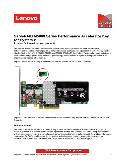
ServeRAID M5000 Series Performance Accelerator Key for System xProduct Guide (withdrawn product)The ServeRAID M5000 Series Performance Accelerator Key for System x® enables performance enhancements needed by emerging SSD technologies via a seamless field-upgradeable key. This key can be attached to the ServeRAID M5025, M5015, and M5014 SAS/SATA Controllers. These features are optimized to cater to the emerging solid state drive (SSD) technology, which delivers a higher level of performance in an organization's storage infrastructure.Figure 1 shows where the key is installed on a ServeRAID M5015 SAS/SATA Controller.Figure 1. The ServeRAID M5000 Series Performance Accelerator Key and the ServeRAID M5015 SAS/SATA ControllerDid you know?The M5000 Series Performance Accelerator Key is ideal for supporting server mission-critical applications where high levels of sustained read and write operations are required (such as video streaming, web content, video-on-demand, security and surveillance, fixed content, and reference data storage). It provides performance optimization for SSDs, enables data tiering, and provides important data recovery features to safeguard valuable data. Additionally, the accelerator key provides RAID 6 and 60 and SED support.Click here to check for updatesFigure 2. Location of the Performance Accelerator Key on the supported adaptersSupported ServeRAID controllersTable 2 lists the ServeRAID SAS/SATA controllers that support the Performance Accelerator Key.Table 2. Supported ServeRAID controllersServeRAID M5000 Series Performance Accelerator Key Y Y Y N N N N N N N N N N N N The minimum firmware level required for the supported adapters to enable the use of the Performance Accelerator Key is v12.7.0-0020. The latest firmware is available from:/support/entry/portal/docdisplay?lndocid=MIGR-5073015The ServeRAID M5000 Series Performance Accelerator Key cannot be installed at the same time as the ServeRAID M5000 Series Advanced Feature Key, 46M0930. The Advanced Feature Key must be removed before the Performance Accelerator Key is installed. The functions of the Advanced Feature Key are provided by the Performance Accelerator Key. No further migration steps are needed.Supported serversThe ServeRAID M5000 Series Performance Accelerator Key is supported on the System x servers listed in Table 2.Table 2. Supported System x servers (part 1)ServeRAID M5000 Series Performance Accelerator Key81Y4426N N Y N Y N N Y Y N N Y Y Table 2. Supported System x servers (part 2)ServeRAID M5000 Series Performance Accelerator Key N Y Y N N N N Y Y N Y N N N N Y See the ServerProven website for the latest information about the adapters supported by each System x server type:/us/en/serverproven/Once the hardware key has been installed on the controller, the Recovery, Safestore, and CacheCade Features can be configured through the WeBIOS or MegaRAID Storage Manager Utilities. Figure 3 shows the LSI MegaRAID Storage Manager Dashboard View.Figure 3. LSI MegaRAID Storage Manager Dashboard ViewMegaRAID RecoveryMegaRAID Recovery enhances the ServeRAID data protection feature set by offering snapshot functionality that allows users to capture source volume data changes and either Restore-from-View or Rollback to a previous point in time (PiT) should accidental or malicious data deletion or infection occur. While traditional overnight backups continue to be the preferred method for creating physical copies of data for offsite or archival purposes, MegaRAID Recovery meets a growing need for more frequent backups and reduced recovery times. By supplementing traditional backup methods with MegaRAID Recovery, IT organizations can greatly enhance their level of business continuity, data protection, and restore capabilities.How MegaRAID Recovery worksMegaRAID Recovery preserves the state of information stored on a virtual drive at a specific point in time using a copy-on-write methodology. This means that when data is written to a designated volume or virtual drive (VD), the original data that was present before being written over is then copied to a snapshot repository. The VD will continue to accept new data while copying original data to the repository. The snapshot repository will then continue to collect the original data that is being written over until a snapshot event takes place. Once a snapshot is taken, all of the new and old data on the VD becomes original data. So the repository never becomes a complete copy of the source VD.Figure 4 shows a server with three VDs and a single snapshot repository.Figure 4: Server with three VDs and a single snapshot repositoryThe Volume Shadow Copy Service (VSS) provides the backup infrastructure for the Microsoft Windows XP and Microsoft Windows Server 2003 operating systems. VSS has native support, using a standard set of application programming interfaces (APIs) for creating consistent point-in-time copies of data, regardless of the snapshot technology or application. As a certified Microsoft VSS Provider, MegaRAID Recovery can be initiated by VSS in order to create PiT volume snapshots on demand. This functionality provides a straight-forward and standard way to produce clean snapshots of a volume while coordinating with different types of business applications,file-system services, backup applications, and storage hardware.MegaRAID FastPathMegaRAID FastPath is a high-performance IO accelerator for solid state drive (SSD) arrays connected to a ServeRAID controller card. This advanced software is an optimized version of ServeRAID technology that can dramatically boost storage subsystem and overall application performance -- particularly those that demonstrate high random read/write operation workloads -- when deployed with a M5000-series controller connected to SSDs.Enabling MegaRAID FastPathEnabling MegaRAID FastPath does not require any special configuration. Simply connect the Performance Accelerator Key to the ServeRAID controller and MegaRAID FastPath will be enabled. As the user implements SSDs into an array, he should see a significant increase in overall application performance. Application workloads that will benefit most from MegaRAID FastPath with SSD volumes are those with small and random I/O patterns requiring high transactional throughput, such as OLTP.RAID 0 random workload performanceWith MegaRAID FastPath enabled, SSD configurations tuned for small, random block-size IO activity — typical of transactional database applications — can sustain over 150,000 I/O reads per second in RAID 0 configurations. This is two times the transactional performance of identical configurations when the MegaRAID FastPath software is disabled. This is particularly evident in 4 K random reads and random writes, as well as 4 K and 8 K OLTP transaction-oriented benchmarks.In Figure 5, note that in the standard mode where MegaRAID FastPath software is not enabled, arrays are able to reach more than 80,000 IOPs. This is due to additional performance tuning optimizations over previous 6 Gbps MegaRAID SATA+SAS generations. However, with the MegaRAID FastPath software enabled, users can experience more than a 70% increase in IOPs throughput.Figure 5. Performance benefits of having MegaRAID FastPath enabled (light green) versus disabled (dark green) - RAID 0 random workloadsRAID 5 random workload performanceIn Figure 6, read performance in RAID 5 configurations demonstrates similar IOP performance as RAID 0. When comparing RAID 5 write performance, MegaRAID FastPath software demonstrates 2.5 times the IOP's performance over an identical configuration with this feature disabled.Figure 6. Performance benefits of having MegaRAID FastPath enabled (lighter color) versus disabled (darker color) - RAID 5 random workloadsRAID 0 application performanceMegaRAID FastPath software significantly boosts server application performance levels for typical workloads as well. MegaRAID controllers with MegaRAID FastPath software disabled are limited to 80,000 IOPs, whereas application performance improves by up to 45% with MegaRAID FastPath software enabled (Figure 7).Figure 7. Typical workloads - RAID 0MegaRAID CacheCadeMegaRAID CacheCade software allows customers to blend inexpensive SATA or SAS hard disk drives (HDDs) with a small amount of solid state storage capacity to provide a substantial performance boost while avoiding complete 1:1 replacement of SATA HDDs with faster SAS HDDs, adding additional SATA HDDs or moving to an all-SSD RAID volume to achieve performance requirements. This combination of HDDs and SSDs as secondary cache helps improve IOPs per dollar, particularly in random read-intensive applications. Simply select an SSD and associate it with one or more virtual drives to configure and use CacheCade software.How CacheCade worksCertain applications access different data sectors more frequently than other data sectors. By determining which data is accessed more frequently, it is possible to move the more frequently accessed data to a faster media, allowing for faster overall READ performance from the controller. CacheCade software allows for frequently read data (hot-spot) to be moved to second-tier SSD cache for much faster retrieval of that data when it is time for it to be re-read. This provides significant performance improvement of 2x to 50x for read-intensive applications such as web, file, SQL, and other transactional server applicationsFigure 8. CacheCade in actionEnabling CacheCadeOnce the Performance Accelerator Key is connected to the M5000 Series Controller, CacheCade can be configured through the MegaRAID Storage Manager Utility. When configuring for CacheCade, it is necessary to make sure that no volume data be stored on the available SSDs prior to creating the SSD cache.Performance impactCacheCade uses SSDs to super-swell the M5000 Series controller cache. As with any other SSD caching implementation, the amount of performance improvement that is achieved differs depending on the application that is running. For this generation, users will see greater performance gains in READ-intensive applications. Supported operating systemsTrademarksLenovo and the Lenovo logo are trademarks or registered trademarks of Lenovo in the United States, other countries, or both. A current list of Lenovo trademarks is available on the Web athttps:///us/en/legal/copytrade/.The following terms are trademarks of Lenovo in the United States, other countries, or both:Lenovo®ServeRAIDServerProven®System x®The following terms are trademarks of other companies:Linux® is the trademark of Linus Torvalds in the U.S. and other countries.Microsoft®, Windows Server®, and Windows® are trademarks of Microsoft Corporation in the United States, other countries, or both.Other company, product, or service names may be trademarks or service marks of others.。

1. Safety ..............................................2 2. Equipment Included (3)Light System Parts for Assembly (3)3. Assembly Instructions/Diagrams ....... 4-5 4. Features & Specification......................6 5. Operation .. (7)Treatment Settings ………………......8-96. Maintenance (9)Warranty (10)Teeth Whitening Accelerator Manufacturer warrants that for a period of one year from the date of purchase this instrument shall be free from defects in material and workmanship and will perform satisfactory under normal use and service. It is the responsibility of the user to comply with all manufacturer assembly, operation, and maintenance instructions provided. This will ensure safe use, consistent results, and maintain rights to warranty.This warranty does not cover damages caused by natural disaster or misuse.Our liability with respect to this product is expressly limited to the specifications set forth above. We shall under no circumstances be liable for incidental or consequential damages.*Manual is subject to change without prior notice.Limited Warranty*Table Of ContentsPLEASE NOTE:Prior to assembly and use of this unit, carefully read the instructions provided herein. As with all technical devices, the proper function and safe operation of this unit depend on the user’s compliance with the safety recommendations.CAUTION: Persons with a history of photosensitivity or who are using photosensitizing drugs should not beexposed to the light from this unit.CAUTION: This equipment is not suitable for use in the presence of flammable anesthetic mixtures with air or nitrous oxide.emitting from this unit when it is in use. Be sure to wear the protective eye glasses provided.by flexible light arm. This will affect the warranty.MaintenanceCleaning Light SystemThe outer case of the light system control panel is madeup of plastic and metal materials. Proper cleaning consists of spraying a soft cloth with mild soapy solution and wiping the outside surface of the unit.Cleaning LED Light IlluminatorLED light Illuminator should always be used with plastic sheath on to protect the light from damage and debris. Replace sheath when needed to maintain sanitary condition3. Pause Treatment: Stop the timer and light by pressing the “PAUSE” button. The remaining time will display on the digital time indicator. Press the button again to continue.do not turn off main power switch.5. Please turn off main power switch at the end of the day.SafetyLight System Parts 17 QTY (1 Box)Remote Control 1 QTYPower Cable (8ft.) 1 QTY Plastic Sheath 20 QTY (1 Box)Safety Glasses 2 QTYUser Manual1 QTYEquipment IncludedLight System Parts for Assembly(1 QTY)(1 QTY)(1 QTY)(1 QTY)(1 QTY)(1 QTY)(1 QTY)(5 QTY)(1 QTY)Light System ControlInfrared Remote ControlTreatment Settings(Applicable for System Control Panel or Remote Control)1. Setting the Timer: Use the “Up” or “Down” button to adjust treatment time to 20 minutes.2. Turn On/Off the light and timer by pressing the “START/STOP” button.(Steps continue on page 9.)Assembly InstructionsStep 1:Insert Part 1 into Part 2 and slide Part 3 over the junction to create the wheel base.Step 2:Slide Part 4 onto Part 5 and slide screw up through the bottom of the wheel base. Screw Part 5 into Part 6 and tighten with wrench provided.(1)(2)(3)(4)(5)(6)3. Once whitening tray is inserted into the patient’s bend the light arm to position the light ½ an inch from the patients treatment tray.1. Plug the power cord into the socket on the back of the system control panel. Confirm wall outlet to assure cord and plug in is suitable to your outlet.2. Turn on the power switch on the back of the control panel.FusePower SwitchP roduct Features♦ High efficiency goose neck arm design, adjustable and convenient. ♦ Combination of high power BLUE led.♦ Programmable bleaching time with microprocessor-controlled timer presets.♦ Digital indicator with audio feedback♦ Smart auto-select power: 100-240V 50/60 Hz for global use. ♦ High speed Multi-Arch teeth whitening system♦ Small base size design, suitable for use in dental offices ♦ Uniformity of light output (see product specifications below). ♦ Infrared remote control setting function♦ Enclosed disposable sheath, prevents cross-infection, clean and convenient.Product Specifications♦ Broad Spectrum: 430nm-490nm♦ Light Output Power: U to 2000 mW/cm2 ♦ 100-240V, 50/60Hz ♦ Weight: 4.7Kg♦ Max. Working Radius: 50cm ♦ Uniform light outputStep 3:Align screw holes on top of Part 7 with the bottom of the light system control panel. Insert 5 screws and tighten with Phillips head screwdriver provided.(Light System Control Panel)。
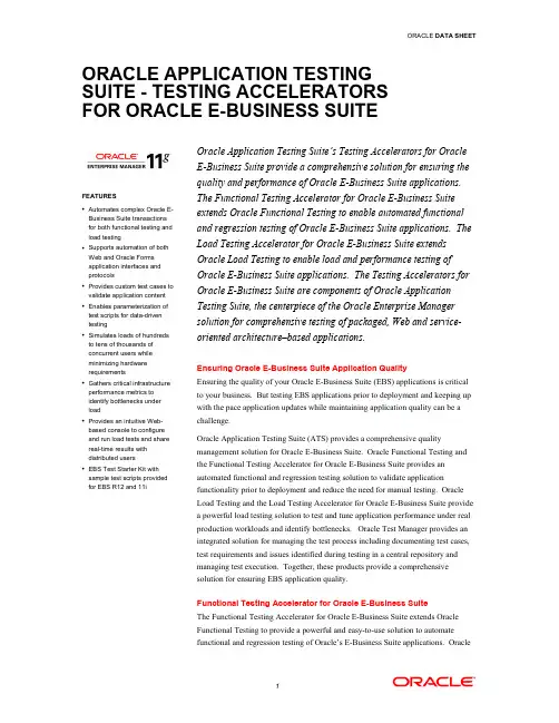
ORACLE APPLICATION TESTING SUITE - TESTING ACCELERATORS FOR ORACLE E-BUSINESS SUITEFEATURES• Automates complex Oracle E-Business Suite transactionsfor both functional testing andload testing• Supports automation of bothWeb and Oracle Formsapplication interfaces andprotocols• Provides custom test cases tovalidate application content• Enables parameterization oftest scripts for data-driventesting• Simulates loads of hundredsto tens of thousands ofconcurrent users whileminimizing hardwarerequirements• Gathers critical infrastructureperformance metrics toidentify bottlenecks underload• Provides an intuitive Web-based console to configureand run load tests and sharereal-time results withdistributed users• EBS Test Starter Kit withsample test scripts providedfor EBS R12 and 11iOracle Application Testing Suite’s Testing Accelerators for Oracle E-Business Suite provide a comprehensive solution for ensuring the quality and performance of Oracle E-Business Suite applications. The Functional Testing Accelerator for Oracle E-Business Suite extends Oracle Functional Testing to enable automated functional and regression testing of Oracle E-Business Suite applications. The Load Testing Accelerator for Oracle E-Business Suite extends Oracle Load Testing to enable load and performance testing of Oracle E-Business Suite applications. The Testing Accelerators for Oracle E-Business Suite are components of Oracle Application Testing Suite, the centerpiece of the Oracle Enterprise Manager solution for comprehensive testing of packaged, Web and service-oriented architecture–based applications. Ensuring Oracle E-Business Suite Application Quality Ensuring the quality of your Oracle E-Business Suite (EBS) applications is critical to your business. But testing EBS applications prior to deployment and keeping up with the pace application updates while maintaining application quality can be a challenge. Oracle Application Testing Suite (ATS) provides a comprehensive quality management solution for Oracle E-Business Suite. Oracle Functional Testing and the Functional Testing Accelerator for Oracle E-Business Suite provides an automated functional and regression testing solution to validate application functionality prior to deployment and reduce the need for manual testing. Oracle Load Testing and the Load Testing Accelerator for Oracle E-Business Suite provide a powerful load testing solution to test and tune application performance under real production workloads and identify bottlenecks. Oracle Test Manager provides an integrated solution for managing the test process including documenting test cases, test requirements and issues identified during testing in a central repository and managing test execution. Together, these products provide a comprehensive solution for ensuring EBS application quality. Functional Testing Accelerator for Oracle E-Business Suite The Functional Testing Accelerator for Oracle E-Business Suite extends Oracle Functional Testing to provide a powerful and easy-to-use solution to automate functional and regression testing of Oracle’s E-Business Suite applications. OracleFunctional Testing allows users to create test scripts that automate complex business transactions within their EBS applications, including both Web and Oracle Forms based application interfaces. Oracle Functional Testing’s OpenScript integrated scripting platform combines an intuitive graphical scripting interface to quickly create complex test scripts and a powerful Java IDE that provides users with the flexibility to extend scripts programmatically. Users can automate business transactions by simply creating a new script and recording as they step through an EBS transaction in a browser. OpenScript captures all actions performed within Web or Forms based applications interfaces which can then be played back to automatically reproduce the recorded transaction. Users can then add test cases to validate specific Web or Forms application content and parameterize their script inputs to perform data-driven testing. Additional transactions can then be recorded to create a comprehensive automated regression test suite.Figure1. Oracle Functional Testing automates Oracle E-Business Suite functional and regression testingLoad Testing Accelerator for Oracle E-Business SuiteThe Load Testing Accelerator for Oracle E-Business Suite extends Oracle Load Testing to enable automated load and performance testing of Oracle E-Business Suite applications. With Oracle Load Testing you can simulate thousands of virtual users accessing the Oracle E-Business Suite application simultaneously to measure the effect of user load on application performance.Users create their EBS load test scripts in Oracle Functional Testing’s OpenScript integrated scripting platform. OpenScript automates both Web and Forms application protocols to generate highly scalable load test scripts for Oracle EBS. The scripts are automatically correlated to handle dynamic session parameters. These scripts can then be configured to run in Oracle Load Testing against any number of virtual users.Oracle Load Testing provides a Web-based console that allows you to configure and run one or multiple scripts across thousands of virtual users to assess performance. Users can specify a number of run time parameters such as the amount of think time each user spends per page and the browser or connection speed to emulate. During the load test, Oracle Load Testing measures end-user response times as well as the performance of the underlying application infrastructure to help identify and resolve application performance bottlenecks.Comprehensive Testing for Oracle E-Business SuiteOracle Application Testing Suite provides a comprehensive testing solution for Oracle E-Business Suite. With Oracle Functional Testing and the Functional Testing Accelerator for Oracle E-Business Suite, users can effectively introduce automation into their functional test process to ensure the quality of their Oracle E-Business Suite applications and reduce testing time. With Oracle Load Testing and the Load Testing Accelerator for Oracle E-Business Suite, users can leverage a powerful solution for ensuring Oracle E-Business Suite application performance. The Oracle E-Business Suite testing accelerator includes a Test Starter Kit with pre-build test automation scripts for Oracle E-Business Suite applications. The Test Starter Kit covers a broad range of applications and user flows for both functional and performance testing based on the VISION demo database.And with Oracle Test Manager users can effectively document and manage their test process from a central location and report on application readiness.Oracle Application Testing Suite provides a powerful integrated scripting platform for automated functional & regression testing and load testing. Oracle Functional Testing’s OpenScript integrated scripting interface provides a unique combination of ease-of-use and flexibility through its intuitive graphical scripting interface and powerful Java IDE for extending scripts at the code-level. Oracle Functional Testing also provides custom capabilities for testing SOA and Oracle packaged applications through its integrated testing accelerators. Oracle Load Testing provides a fully Web-based user interface for configuring and running load tests and an integrated ServerStats module for monitoring application infrastructure during a load test to identify bottlenecks. Oracle Load Testing also enables multi-user collaboration by allowing testers to view and share real-time results during load test execution through their browser. With Oracle Application Testing Suite users can leverage a comprehensive, integrated solution for automated functional and regression testing, load testing and test process management.Contact UsFor more information about Oracle Application Testing Suite Oracle E-Business Suite Accelerators and Oracle Enterprise Manager please visit or call+1.800.ORACLE1 to speak to an Oracle representative.Copyright © 2011, Oracle and/or its affiliates. All rights reserved.This document is provided for information purposes only and the contents hereof are subject to change without notice. This document is not warranted to be error-free, nor subject to any other warranties or conditions, whether expressed orally or implied in law, including implied warranties and conditions of merchantability or fitness for a particular purpose. We specifically disclaim any liability with respect to this document and no contractual obligations are formed either directly or indirectly by this document. This document may not be reproduced or transmitted in any form or by any means, electronic or mechanical, for any purpose, without our prior written permission.Oracle and Java are registered trademarks of Oracle and/or its affiliates. Other names may be trademarks of their respective owners.AMD, Opteron, the AMD logo, and the AMD Opteron logo are trademarks or registered trademarks of Advanced Micro Devices. Intel and Intel Xeon are trademarks or registered trademarks of Intel Corporation. All SPARC trademarks are used under license and are trademarks or registered trademarks of SPARC International, Inc. UNIX is a registered trademark licensed through X/Open Company, Ltd. 0110。

Sun Microsystems, Inc.4150 Network CircleSanta Clara, CA 95054 U.S.A.650-960-1300请访问以下网址来提交您对本文档的意见/hwdocs/feedbackSun Fire™ V880z 服务器和Sun™ XVR-4000图形加速器安装与用户指南部件号 817-2636-102003 年 5月修订版 A请回收版权所有 2003 Sun Microsystems, Inc., 4150 Network Circle, Santa Clara, California 95054, U.S.A. 保留所有权利Sun Microsystems, Inc. 拥有与本文档所述产品包含的技术有关的知识产权重点来讲但不限于此这些知识产权包括/patents网站列出的一个或多个美国专利以及一个或多个在美国或其它国家/地区注册的其它专利或正在申请中的专利本文档及其所述产品的发行受限制其使用复制发行和反编译的许可证的制约未经 Sun 及其许可证发行者如果有事先书面授权不得以任何形式任何方式复制本产品或文档的任何部分第三方软件包括字体技术均已从 Sun 供应商处取得版权和使用许可产品的部分部件可能源于 Berkeley BSD 系统Sun 已从 University of California 获得使用许可UNIX 是在美国及其它国家/地区的注册商标Sun 已从 X/Open Company , Ltd. 获得独家使用授权SunSun Microsystems Sun 徽标Sun FireJava3DJavaOpenBoot 和 Solaris 是 Sun Microsystems,Inc. 在美国及其它国家/地区的商标或注册商标所有 SPARC 商标都是 SPARC International, Inc. 在美国以及其它国家/地区的商标或注册商标必须根据许可证条款使用带有 SPARC 商标的产品以 Sun Microsystems, Inc.开发的体系结构为基础OPEN LOOK 和 Sun™ Graphical User Interface 是 Sun Microsystems, Inc. 专门为其用户和许可证获得者开发的Sun 感谢 Xerox 在用户界面形象化和图形化研发方面为计算机行业所做的先导性贡献Sun 已从 Xerox 获得对 Xerox 图形用户界面 (GUI) 的非独占使用许可该许可也涵盖实施 OPEN LOOK GUI 的 Sun 许可获得者而其它情况则应符合 Sun 的书面许可协议OpenGL 是 Silicon Graphics, Inc. 的注册商标文档以原样提供除非有关的免责声明在法律上无效否则 Sun 拒绝承担任何明确或暗示的条件表示和担保包括任何对适销性特定用途的适用性或非侵犯性作出的暗示担保目录ኔዔxi1.Sun XVR-4000 ᅄተଝႥڔᓤগၤ1安装过程概述1软件补丁程序22.Sun XVR-4000 ᅄተଝႥগၤ3安装工具包3Sun XVR-4000 图形加速器概述4屏幕分辨率8查看现场可更换件信息11技术支持123.ڔᓤ Sun XVR-4000 ᅄተଝႥྟୈ13软件要求13Sun XVR-4000 图形加速器软件包14安装软件16iii4.ڔᓤ Sun XVR-4000 ᅄተଝႥ፮ୈ17安装准备工作17在 Sun Fire V880z 服务器中安装硬件18从 Sun Fire V880z 服务器中卸下硬件27Sun XVR-4000 图形加速器电缆30更改显示器屏幕分辨率305.ᒙࣶৈᑷદߡ31通过Xservers文件配置多个帧缓冲器31Xinerama336.ဧ Sun XVR-4000 ᅄተଝႥถ35联机资料35-outputs端口映射36流传送方法38设置流传送方法40多板设置42多次采样抗锯齿43控制抖动和过滤47检查设备配置497.Sun XVR-4000 ᅄተଝႥᑷჄࢾ51Sun XVR-4000 图形加速器帧锁定系统51缓冲器交换同步52创建多屏幕应用53连接帧锁定电缆54在图形加速器上启用帧锁定56禁用帧锁定57帧锁定电缆58iv Sun Fire V880z 服务器和 Sun XVR-4000 图形加速器安装与用户指南•2003 年 5 月8.Sun XVR-4000 ᅄተଝႥᄴݛჄࢾ59Sun XVR-4000 图形加速器同步锁定59连接同步锁定电缆60为图形加速器启用同步锁定62禁用同步锁定67A.ᒙ෦ཱྀࡼ఼ᒜგመာᓤᒙ69B.ᒙ S-Video73C.ڔᓤ OpenBoot PROM ဍۈ81D.Sun Fire V880z ॲᇗဍ83E.Ᏼ Sun Fire V880z ॲᇗᒦڔᓤ Solaris 8 2/02 ྟୈ89F.Sun XVR-4000 ᅄተଝႥ I/O ࣡ాਖৃ99Ⴣ105目录vvi Sun Fire V880z 服务器和 Sun XVR-4000 图形加速器安装与用户指南•2003 年 5 月图图 2-1Sun Fire V880z 服务器4图 2-2装有空气导流盖的 Sun XVR-4000 图形加速器5图 2-3未装有空气导流盖的 Sun XVR-4000 图形加速器5图 4-1Sun Fire V880z 服务器后面板上用于插槽 B 和 C 的盖板18图 4-2打开 Sun Fire V880z 服务器机壳挡门19图 4-3确定 Sun Fire V880z 服务器插槽 B 和 C 的位置20图 4-4从插槽 B 中卸下 Sun Fire V880z 主板总线插槽盖板21图 4-5将 Sun XVR-4000 图形加速器装入插槽 B 连接器22图 4-6在服务器后面板 I/O 插槽 B 上安装后面板 EMI 适配器23图 4-7Sun XVR-4000 图形加速器电源和温度 LED 指示灯24图 4-8Sun XVR-4000 图形加速器 LED 指示灯25图 4-9卸下 Sun XVR-4000 图形加速器28图 4-10装回 Sun Fire V880z 主板总线插槽盖板29图 6-1Sun XVR-4000 图形加速器后面板36图 6-2输出端口映射 (-outputs)37图 6-3多板设置示例43图 7-1Sun XVR-4000 图形加速器立体/帧锁定连接器54图 7-2Sun XVR-4000 图形加速器和帧锁定电缆55图 7-3帧锁定电缆58vii图 8-1Sun XVR-4000 图形加速器 13W3 和同步锁定连接器60图 8-2Sun XVR-4000 图形加速器同步锁定连接61图 8-3Sun XVR-4000 图形加速器同步锁定 LED 指示灯67图 B-1Sun XVR-4000 图形加速器 S-Video DIN4 连接器74图 D-1卸下 Sun Fire V880 服务器前挡板85图 D-2安装 Sun Fire V880z 服务器前挡板86图 F-1Sun XVR-4000 图形加速器后面板 I/O 端口99图 F-2Sun XVR-4000 图形加速器后面板 13W3 连接器100图 F-3Sun XVR-4000 图形加速器后面板立体/帧锁定 DIN7 连接器101图 F-4Sun XVR-4000 图形加速器后面板 S-Video 连接器102图 F-5Sun XVR-4000 图形加速器后面板 BNC 连接器103viii Sun Fire V880z 服务器和 Sun XVR-4000 图形加速器安装与用户指南•2003 年 5 月表表 2-1Sun XVR-4000 图形加速器屏幕分辨率8表 3-1Sun XVR-4000 图形加速器 CD 目录14表 3-2Sun XVR-4000 图形加速器软件包的位置14表 3-3Sun XVR-4000 图形加速器软件包名称15表 3-4Sun XVR-4000 图形加速器补丁程序目录15表 3-5Sun XVR-4000 图形加速器补丁程序15表 6-1多次采样选项说明44表 6-2典型多次采样支持44表 6-3-jitter选项47表 6-4-filter选项48表 7-1帧锁定电缆连接58表 8-1屏幕分辨率同步属性65表 F-1Sun XVR-4000 图形加速器 13W3 连接器插针100表 F-2Sun XVR-4000 图形加速器立体/帧锁定连接器插针101表 F-3Sun XVR-4000 图形加速器 S-Video 连接器插针102表 F-4Sun XVR-4000 图形加速器 BNC 连接器插针103ixx Sun Fire V880z 服务器和 Sun XVR-4000 图形加速器安装与用户指南•2003 年 5 月xi序言本手册讲述如何在 Sun Fire ™ V880z 服务器中安装 Sun ™ XVR-4000 图形加速器及相关软件此外它还介绍了将 Sun Fire V880 服务器升级至 Sun Fire V880z 服务器的过程ᓖ – Sun Fire XVR-4000 图形加速器和 Sun Fire V880z 服务器必须 由合格的服务人员管理和维修本书的内容编排第 1 章概述 Sun XVR-4000图形加速器的安装过程第 2 章简要介绍 Sun XVR-4000 图形加速器包括产品功能和支持的视频格式第 3 章说明如何安装 Sun XVR-4000图形加速器软件第 4 章说明如何安装 Sun XVR-4000图形加速器硬件第 5 章介绍如何修改 Xservers 配置文件从而运行多个帧缓冲器第 6 章提供有关使用 Sun XVR-4000图形加速器功能的信息包括通过 fbconfig配置加速器多次采样和多次采样抗锯齿功能第 7 章介绍如何对多个 Sun XVR-4000图形加速器进行帧锁定第 8 章说明如何对多个 Sun XVR-4000图形加速器进行同步锁定附录 A 说明如何将 Sun XVR-4000图形加速器设置为默认的显示器控制台显示装置附录 B 介绍如何在 Sun XVR-4000 图形加速器上设置 S-video NTSC 和 PAL 视频格式xii Sun Fire V880z 服务器和 Sun XVR-4000 图形加速器安装与用户指南•2003 年 5 月附录 C 说明如何安装 OpenBoot PROM 4.7.0升级版附录 D 介绍如何将 Sun Fire V880 服务器升级至配有 Sun XVR-4000 图形加速器的 Sun Fire V880z服务器附录 E 提供有关使用 Sun Fire V880z Operating Environment Installation DVD 的信息附录 F 提供 Sun XVR-4000 图形加速器的 I/O端口规格使用 UNIX 命令本文档没有介绍基本 UNIX ® 命令和操作过程的有关信息如关闭系统启动系统和配置设备等有关此类信息的详细说明请参阅以下文档I Solaris Handbook for Sun PeripheralsI 用于 Solaris ™ 软件环境的 AnswerBook2™ 联机文档I系统附带的其它软件文档印刷约定ᔊዹ९ፃာಿAaBbCc123命令文件和目录的名称计算机的屏幕输出编辑您的 .login文件使用 ls -a列出所有文件% You have mail.AaBbCc123键入的内容相对于屏幕上的计算机输出% suPassword:AaBbCc123书的标题新词或术语需要强调的词需用真名或实际值替换命令行变量阅读用户指南 中的第 6章这些选项称为 class 选项要删除文件请键入 rm文件名序言xiiishell 提示相关文档访问 Sun 文档用户可从以下网站查看打印或订购 Sun 提供的各类文档包括本地化版本/documentationshellᄋာ९C shell计算机名%C shell 超级用户计算机名#Bourne shell 和 Korn shell$Bourne shell 和 Korn shell 超级用户#።ၗݝୈ维修Sun Fire V880 Server Service Manual 806-6597系统选项Sun Fire V880 服务器用户指南816-0756xiv Sun Fire V880z 服务器和 Sun XVR-4000 图形加速器安装与用户指南•2003 年 5 月联系 Sun 技术支持人员如果遇到本文档不能解决的产品技术问题请访问以下网址/service/contactingSun 欢迎您提出意见Sun十分注重改进自身文档的质量并欢迎您提出宝贵的意见和建议您可通过访问以下网址来提交您的意见/hwdocs/feedback请在反馈意见中注明本文档的书名和部件号Sun Fire V880z 服务器和 Sun XVR-4000图形加速器安装与用户指南部件号 817-2636-101第章1Sun XVR-4000 图形加速器安装概述本章介绍 Sun XVR-4000 图形加速器的安装过程有关 Sun XVR-4000图形加速器Sun Fire V880z 服务器和安装工具包内容的概述请参阅第 2 章ᓖ – Sun Fire XVR-4000 图形加速器和 Sun Fire V880z 服务器必须由合格的服务人员管理和维修I 第 1页的安装过程概述I第 2页的软件补丁程序安装过程概述共有三种不同的安装情况请选用其中一个适用的安装过程在 Sun Fire V880z 服务器上安装 Sun XVR-4000 图形加速器软件Sun XVR-4000 图形加速器 DVD 和 Solaris CD 只适用于 Solaris 8 2/02操作环境1. 放入 Sun Fire V880z Operating Environment Installation DVD然后从中引导系统第 3章2. 安装 Solaris 8 2/02软件第 3章3.出现提示时放入 Solaris CD安装 Solaris之后系统会重新引导继续步骤4如果您安装的是 Solaris 9 4/03操作环境则在安装之后无需进一步安装软件因为该 Solaris 版本或更高版本已包含了配有 Sun XVR-4000 图形加速器的 Sun Fire V880z 服务器所需的软件否则请继续步骤4以从 Sun XVR-1000 图形加速器 CD 中安装 OpenGL 1.3Sun XVR-4000图形加速器补丁程序以及额外的值软件2Sun Fire V880z 服务器和 Sun XVR-4000 图形加速器安装与用户指南•2003 年 5 月4. 将 Sun XVR-4000 图形加速器 CD 放入 DVD驱动器第 3章然后键入5. 根据需要安装第二个 Sun XVR-4000 图形加速器硬件第 4章Sun Fire V880z已安装了一个 Sun XVR-4000 图形加速器6. 通过 Xservers文件配置软件第 5章如有必要也可通过 fbconfig 配置软件第 6章从一个 Sun XVR-4000 图形加速器升级至两个1.编辑两个 Sun XVR-4000 图形加速器的 Xservers配置文件第 5章2. 安装第二个 Sun XVR-4000图形加速器硬件第 4章将 Sun Fire V880 服务器升级至 Sun Fire V880z 服务器此升级过程包括硬件软件前门和前挡板的安装步骤1.系统要求使用 OpenBoot PROM 4.7.0 或更高版本如果 OpenBoot PROM 版本低于4.7.0请安装 OpenBoot PROM升级版本附录C 2. 执行 Sun Fire V880z服务器升级附录D 3. 通过 Xservers文件配置软件第 5章如有必要也可通过 fbconfig 配置软件第 6章软件补丁程序确保您安装了正确的的补丁程序 第 3章列出了产品软件包和补丁程序有关最新的软件补丁程序请随时访问 / 网站# cd /cdrom/cdrom0# ./install3第章2Sun XVR-4000 图形加速器概述本章简要介绍了 Sun Fire V880z 服务器的 Sun XVR-4000 图形加速器I 第 3页的安装工具包I 第 4页的Sun XVR-4000 图形加速器概述I 第 8页的屏幕分辨率I 第 11 页的查看现场可更换件信息I第 12 页的技术支持有关 Sun Fire V880z服务器的详细信息请参阅 Sun Fire V880服务器文档I Sun Fire V880 Server Service Manual (806-6597)ISun Fire V880 服务器用户指南 (816-0756)安装工具包Sun XVR-4000图形加速器安装工具包包括I Sun XVR-4000 图形加速器I Sun XVR-4000 图形加速器软件 CDI Sun Fire V880z Operating Environment Installation DVD I 13W3 到 HD15 显示器电缆适配器I 防静电腕带ISun Fire V880z Server and Sun XVR-4000 Graphics Accelerator Installation and User's Guide 即本文档有关其它电缆信息请参阅第 30 页的Sun XVR-4000图形加速器电缆4Sun Fire V880z 服务器和 Sun XVR-4000 图形加速器安装与用户指南•2003 年 5 月Sun XVR-4000 图形加速器概述Sun XVR-4000图形加速器是一款高性能可实现相片质量的 3D图形加速器它在Sun Fire V880z 服务器的 Sun ™ Fireplane互连总线上运行图2-1应用程序界面包括 Sun OpenGL ® 1.3 for Solaris 和 Java3D ™通过 Java ™ Advanced Imaging API可以支持成像Sun XVR-4000图形加速器通过提供极高性能的渲染并提供每时每刻的全景抗锯齿在视觉上产生了栩栩如生的效果从而实现预期的高质量抗锯齿渲染ᅄ 2-1Sun Fire V880z 服务器第 2 章Sun XVR-4000 图形加速器概述5图 2-2 和图 2-3 分别显示了装有和未装有空气导流盖的 Sun XVR-4000图形加速器 附录 F介绍了后面板上的 I/O端口ᅄ 2-2装有空气导流盖的 Sun XVR-4000 图形加速器ᅄ 2-3未装有空气导流盖的 Sun XVR-4000图形加速器6Sun Fire V880z 服务器和 Sun XVR-4000 图形加速器安装与用户指南•2003 年 5 月Sun XVR-4000 图形加速器功能质量I 通过视频速率达 5 × 5 的像素处理阵列实现行业领先的抗锯齿质量I 支持 30位颜色精度提供更广更精确的色域I 12 位有效线性光预灰度系数颜色精度I26 位浮点 Z缓冲实现比 32 位整数 Z 缓冲更有效的深度分辨率性能I 几何处理速率高达每秒 65M 个硬件纹理三角形I全几何速率时达 256 MB的纹理内存或在几何速率降低时达 1 GB的纹理内存使用目标纹理 OpenGL扩展I在 Sun Fireplane 互连总线上的高性能 DMA灵活性I 通过能够同时运行不同分辨率的两个 10 位视频 DAC 和 13W3输出端口支持两个异步视频流I经优化用于超取样的 144 MB高分辨率样本缓冲器保持高达 10 M 的图像样本值而不是像素值允许用户在屏幕分辨率与每像素样本数之间折衷选择由 32 3DRAM64 帧缓冲器内存芯片实现I 在帧缓冲器容量和 Convolve 带宽限制范围内可持续设定分辨率I在具有已过滤的抗锯齿像素的相同屏幕上支持非过滤的 X-Windows 像素扩展性I使用四个平行图形处理引擎四个 Cafe 处理器和四个FBC3 ASIC 的硬件几何加速第 2 章Sun XVR-4000 图形加速器概述7标准X-WindowsOpenGLI 视频端口剪辑I 窗口 ID (WID) 剪辑用于超过八个交叠窗口的辅助剪辑硬件I 64 个主 X Windows 窗口 ID 15 个重叠窗口 IDI 每个视频流中有四个 3 × 256 10 位彩色图伪颜色或调配色I每个视频流有一个 3 × 4096 10 位可调整灰度系数校正表用于真彩色单独的红色绿色和蓝色灰度系数视频操作Sun XVR-4000 图形加速器支持以下视频输出和功能默认视频端口可以是 13W3A 视频端口也可以是 13W3B 视频端口具体通过 fbconfig选定参阅第 6章视频输出Sun XVR-4000图形加速器支持两个同步视频流这些视频流可用于多种用途例如在两个高分辨率的显示器或投影仪上分别显示共享的帧缓冲器区域在两个显示设备上显示两个不同高分辨率的 X-window 系统屏幕或者在显示器上显示高分辨率的图像并在高分辨率显示器上同步显示 NTSC分辨率的内容ᓖ –如果情景内容在两个视频流之间共享即内容来源于共享帧缓冲器而不是独立的帧缓冲器垂直速率必须一致才能在两个视频输出上获得正确的显示S-Video 功能对于 S-video 输出NTSC 或PAL 主显示屏的任何子区域最大到整个显示屏均可重新调整至 NTSC 或 PAL以便进行录像等操作I从主视频桌面的一部分到 TV/VCR视频输出端口可为 NTSC视频格式刷新率60 Hz 分辨率 640 ×480和 PAL视频格式刷新率50Hz 分辨率 640 ×480提供次视频输出流I TV/VCR 视频输出是S-video采用适当的机械连接I如果未使用 S-video 输出则可使用第二个 13W3输出以实现高分辨率显示8Sun Fire V880z 服务器和 Sun XVR-4000 图形加速器安装与用户指南•2003 年 5 月屏幕分辨率Sun XVR-4000 图形加速器能够以支持的所有分辨率显示全部 30 位3D 双/z 缓冲图形 表 2-1 列出了 Sun XVR-4000图形加速器支持的屏幕分辨率GገࡻჅᎌᅄተ۸ࡼܭ༿ྜྷG ገࡻመာ۸ࡼభॊܦൈܭ༿ྜྷhost% fbconfig -listhost% fbconfig -dev zulu0 -res \?ܭ 2-1 Sun XVR-4000 图形加速器屏幕分辨率መာॊܦൈၮቤൈ (Hz)ܪᓰᔑ੯܈ၒ߲࣡ా၁ຫৃါ1920 × 120060d Sun 16:1013W3SUNW_DIG_1920x1200x601920 × 12007075Sun 16:1013W3SUNW_STD_1920x1200x70SUNW_STD_1920x1200x751920 × 108060d Sun 16:913W3SUNW_DIG_1920x1080x601920 × 108072Sun 16:913W3SUNW_STD_1920x1080x721792 × 134460VESA 4:313W3VESA_STD_1792x1344x601600 × 128076Sun 5:413W3SUNW_STD_1600x1280x761600 × 120060d Sun 4:313W3SUNW_DIG_1600x1200x601600 × 12006075VESA 4:313W3VESA_STD_1600x1200x60VESA_STD_1600x1200x751600 × 102460Sun 16:1013W3SUNW_DIG_1600x1024x60 或SUNW_STD_1600x1024x601600 × 10006676Sun 16:1013W3SUNW_STD_1600x1000x66SUNW_STD_1600x1000x761440 × 90076Sun 16:1013W3SUNW_STD_1440x900x761280 × 102496112Sun stereo 5:413W3SUNW_STEREO_1280x1024x96SUNW_STEREO_1280x1024x1121280 × 1024108dSun stereo5:413W3SUNW_STEREO-DIG_1280x1024x1081280 × 1024607585VESA5:413W3VESA_STD_1280x1024x60VESA_STD_1280x1024x75VESA_STD_1280x1024x851280 × 10246776Sun5:413W3SUNW_STD_1280x1024x67SUNW_STD_1280x1024x761280 × 800112Sun stereo16:1013W3SUNW_STEREO_1280x800x112 1280 × 80076Sun16:1013W3SUNW_STD_1280x800x76 1280 × 76856Sun5:313W3SUNW_STD_1280x768x56 1152 × 900120Sun stereo5:413W3SUNW_STEREO_1152x900x1201152 × 9006676Sun5:413W3SUNW_STD_1152x900x66SUNW_STD_1152x900x761024 × 692100Sun stereo4:313W3SUNW_STEREO_1024x692x100 1024 × 80084Sun4:313W3SUNW_STD_1024x800x84 1024 × 76896Sun stereo4:313W3SUNW_STEREO_1024x768x96 1024 × 76877Sun4:313W3SUNW_STD_1024x768x771024 × 768607075VESA4:313W3VESA_STD_1024x768x60VESA_STD_1024x768x70VESA_STD_1024x768x75960 × 680108112Sun stereo14:1013W3SUNW_STEREO_960x680x108SUNW_STEREO_960x680x112800 × 60075VESA4:313W3VESA_STD_800x600x75 768 × 57550i PAL (RGB)4:313W3SUNW_PAL_768x575x50 768 × 57550i Sun4:313W3SUNW_INT_768x575x50 640 × 48060fsc Sun4:313W3SUNW_FSC_640x480x60640 × 480607275VESA4:313W3VESA_STD_640x480x60VESA_STD_640x480x72VESA_STD_640x480x75640 × 48060i SunNTSC (RGB)4:313W3SUNW_INT_640x480x60640 × 48060i NTSC(Composite)4:3S-video SUNW_NTSC_640x480x60640 × 48050i PAL(Composite)4:3S-video SUNW_PAL_640x480x50ܭ 2-1 Sun XVR-4000 图形加速器屏幕分辨率续መာॊܦൈၮቤൈ(Hz)ܪᓰᔑ੯܈ၒ߲࣡ా၁ຫৃါ第 2 章Sun XVR-4000 图形加速器概述910Sun Fire V880z 服务器和 Sun XVR-4000 图形加速器安装与用户指南•2003 年 5 月ᓖ – 刷新率标记为d 的视频格式只适用于 LCD和其它数字设备这些刷新率缩短了不适用于 CRT和其它模拟设备的间隔时间刷新率标记为i的视频格式是隔行扫描方式刷新率标记为fsc的视频格式仅用于特定的场序彩色显示NTSC 和 PAL 复合视频格式仅使用 S-video输出端口虽然 Sun XVR-4000图形加速器支持有线立体眼镜和无线立体眼镜但不 支持那些无外部电源的无线立体眼镜有关说明请参阅第 54页的连接帧锁定电缆第 2 章Sun XVR-4000 图形加速器概述11查看现场可更换件信息您可以使用 fbconfig 命令获得 Sun XVR-4000 图形加速器子部件的版本号和其它数据G ገࡻFRU IDሚޝభৎધୈܪဤ९ቧᇦ༿ྜྷጲሆෘഎhost% fbconfig -dev zulu0 -prconf--- Hardware Configuration for /dev/fbs/zulu0 ---Type: XVR-4000 Graphics Accelerator Part: 501-5588Memory:MAJC: 128MBTexture: 1GB total3DRAM64: 10.0M samplesVersions:Fcode 1.18 MCode 1.4 MAJC 2.1 FBC3 3.0 Master 1.0 Convolve 0.0 Sched 1.0 I/O 0.0 FPGA 1.0 Power Level:Monitor Power: On Board Power: OnVideo Streams: Stream A:Current resolution setting: Flags: Default Primary Monitor/EDID data (13W3)Monitor Manufacturer: SUN EDID: Version 1, Revision 3Stream B:Current resolution setting: Flags: NoneMonitor/EDID data (13W3)EDID Data: Not Available12Sun Fire V880z 服务器和 Sun XVR-4000 图形加速器安装与用户指南•2003 年 5 月技术支持欲了解本文档中未介绍的 Sun XVR-4000图形加速器的帮助和其它信息请访问网站 /service/online 上的Support Services支持服务要获得安装与用户指南的最新版本请访问 /documentation网站13第章3安装 Sun XVR-4000 图形加速器软件本章介绍如何安装 Sun XVR-4000图形加速器软件I 第 13 页的软件要求I 第 14 页的Sun XVR-4000图形加速器软件包I第 16 页的安装软件软件要求ISolaris 8 2/02 操作环境或以后的兼容版本对于 Solaris 8 2/02操作环境您必须 首先安装 Sun XVR-4000 图形加速器安装工具包中附带的 Operating Environment Installation DVD有关此过程的说明请参阅附录EISolaris 9 4/03 操作环境或以后的兼容版本如果您安装的是 Solaris 9 4/03操作环境则在安装之后无需进一步安装软件因为该 Solaris 版本或更高版本已包含了配有 Sun XVR-4000 图形加速器的 Sun Fire V880z 服务器所需的软件有关补丁程序的列表请参见表 3-5有关最新的软件补丁程序信息请随时访问以下网站 /您可从以下网址获取 Sun OpenGL ® for Solaris的更新版本 /software/graphics/OpenGL/14Sun Fire V880z 服务器和 Sun XVR-4000 图形加速器安装与用户指南•2003 年 5 月Sun XVR-4000 图形加速器软件包表 3-1 列出了 Sun XVR-4000 图形加速器 CD 的目录软件包位于目录路径/cdrom/cdrom0/下软件包位置Sun XVR-4000 图形加速器软件包位于表 3-2列出的目录中ܭ 3-1 Sun XVR-4000 图形加速器 CD 目录ഺႁීLicense二进制代码许可证XVR-4000/Solaris_8/Packages/ Solaris 8 图形加速器软件包XVR-4000/Solaris_9/Packages/ Solaris 9 图形加速器软件包Docs/ Sun XVR-4000 图形加速器文档Copyright 美国版权版本FR_Copyright 法国版权版本install 产品安装脚本remove产品删除脚本OpenGL/1.3/Packages/ OpenGL 1.3 软件包OBP/ OpenBoot PROM 更新实用程序README包含重要安装信息的文件ܭ 3-2Sun XVR-4000 图形加速器软件包的位置ྟୈ۞ഺᆡᒙSolaris 8 软件/cdrom/cdrom0/XVR-4000/Solaris_8/Packages Solaris 9 软件/cdrom/cdrom0/XVR-4000/Solaris_9/Packages第 3 章安装 Sun XVR-4000 图形加速器软件15软件包表 3-3 列出了 Sun XVR-4000图形加速器软件包的名称和说明软件补丁程序表 3-4 列出了包含 Solaris操作环境适用的补丁程序的目录表 3-5列出了软件安装所需的补丁程序ܭ 3-3Sun XVR-4000 图形加速器软件包名称ྟୈ۞߂ႁීSUNWzuluc Sun XVR-4000 图形加速器的配置实用程序SUNWzulur Sun XVR-4000 图形加速器引导期间的设备初始化支持SUNWzuluwSun XVR-4000 图形加速器的 X Windows 系统可加载模块SUNWzulux.u Sun XVR-4000图形加速器64位的设备驱动程序SUNWzulum Sun XVR-4000 图形加速器联机资料SUNWvid 一般视频计时信息SUNWgldp Sun OpenGL 1.3 for Solaris 设备管道SUNWgldpxSun OpenGL 1.3 for Solaris设备管道64 位ܭ 3-4Sun XVR-4000 图形加速器补丁程序目录Solaris ۈ۾ᆡᒙSolaris 8 软件/cdrom/cdrom0/XVR-4000/Solaris_8/Patches Solaris 9 软件/cdrom/cdrom0/XVR-4000/Solaris_9/Patchesܭ 3-5 Sun XVR-4000 图形加速器补丁程序ݗࢷ߈ኔܠႁී114469Solaris 8 中的 Sun XVR-4000 图形加速器软件114470Solaris 9 中的 Sun XVR-4000 图形加速器软件113886OpenGL 1.3 32位库任何 Solaris 版本113887OpenGL 1.3 64位库任何 Solaris 版本16Sun Fire V880z 服务器和 Sun XVR-4000 图形加速器安装与用户指南•2003 年 5 月安装软件ᓖ – 对于 Solaris 8 2/02操作环境您必须 首先安装名称为Operating EnvironmentInstallation DVD 的 DVD 有关此过程的说明请参阅附录E如果您安装的是 Solaris 9 4/03操作环境则在安装之后无需进一步安装软件因为该 Solaris 版本或更高版本已包含了配有 Sun XVR-4000 图形加速器的 Sun Fire V880z 服务器所需的软件安装 Solaris 版本或更新版本后从 Sun XVR-4000 Graphics Accelerator CD 中安装 OpenGL 1.3, XVR-4000补丁程序和额外的值软件 下面简要介绍了适于 Solaris 8 2/02操作环境的软件安装过程1.ږᑍএഺE Ᏼ Sun Fire V880z ᒦڔᓤ Solaris 8 2/02ྟୈᒦࡼႁීઁ Sun Fire V880z Operating Environment Installation DVD हྜྷ DVD-ROM དࣅઁ࠭ᒦࡴᇹᄻ2.߲ሚᄋာဟहྜྷSolaris DVD安装 Solaris之后系统会重新引导3. Sun XVR-4000 ᅄተଝႥ CD हྜྷ DVD-ROMདࣅ߅ᆐިઓઁྜྷጲሆഺ4.ࣅ install୭۾ྜྷጲሆෘഎ回应安装提示问题5.ྙਫᆚڔᓤ Sun XVR-4000ᅄተଝႥ፮ୈ༿ڔᓤ6.ᄰਭ Xserversᆪୈᒙྟୈ 5ᐺྙᎌܘገጐభᄰਭ fbconfigᒙྟୈ 6ᐺ若要删除软件请使用 ./remove 命令然后回应 remove 提示问题# cd /cdrom/cdrom0/# ./install17第章4安装 Sun XVR-4000 图形加速器硬件本章介绍如何为 Sun Fire V880z 服务器安装 Sun XVR-4000图形加速器硬件I第 17 页的安装准备工作I第 18页的在 Sun Fire V880z服务器中安装硬件I第 27页的从 Sun Fire V880z服务器中卸下硬件I第 30 页的Sun XVR-4000图形加速器电缆I 第 30 页的更改显示器屏幕分辨率安装准备工作有关如何在安装或拆卸任何内部插件板之前安全关闭系统以及如何在安装之后重新引导系统的正确过程请参阅Sun Fire V880 服务器用户指南网站 /documentation上提供了全套的文档有关 Sun Fire V880z 服务器的详细维修信息请参阅以下硬件文档ISun Fire V880 Server Service Manual (806-6597)I Sun Fire V880 服务器用户指南 (816-0756)18Sun Fire V880z 服务器和 Sun XVR-4000 图形加速器安装与用户指南•2003 年 5 月在 Sun Fire V880z 服务器中安装硬件Sun Fire V880z 服务器最多支持两个 Sun XVR-4000图形加速器装有两个 Sun XVR-4000 图形加速器时系统可以支持四个视频显示设备Sun XVR-4000 图形加速器安装在 Sun Fire V880z CPU 插槽 B 和 C内因此装有一个 Sun XVR-4000 图形加速器的 Sun Fire V880z 系统最多可安装六个 CPU 装有两个 Sun XVR-4000 图形加速器的 Sun Fire V880z 系统最多可安装四个CPUᓖፀ – Sun XVR-4000 图形加速器不是热交换设备1.ਈܕᇹᄻ࢟Ꮞ2.࠭ᇹᄻઁෂۇڰሆመာ࢟಄ރᄿᓖፀ –机箱的交流电源线必须保持连接以确保正确的接地至少保留一条电源线的连接3.Ᏼᇹᄻઁෂۇᑊࡵ᎖ڔᓤ Sun XVR-4000 ᅄተଝႥࡼރݹઁቘሆᑚቋރݹࡼঙۇ图4-1后面板上的填充插槽盖板由四颗十字螺丝固定拧下螺丝并妥善保管以备后用ᅄ 4-1 Sun Fire V880z 服务器后面板上用于插槽 B 和 C的盖板插槽 C 盖板盖板第 4 章安装 Sun XVR-4000 图形加速器硬件194.ࡌఎ Sun Fire V880zॲᇗ૦ఫࡪඡ图4-2a.ဧᇹᄻᏙߓࡌఎݾࡪඡࡼჄb.ኟఎݾࡪඡc.ገ࠭૦ረቘሆࡪඡ༿ࡪඡࡌఎᒗ 90 ࣞઁሶᄋࡪඡᒇᒗৼࢾၴᅙಭ۳ෂۇࡼᑽଦᅄ 4-2 打开 Sun Fire V880z服务器机壳挡门20Sun Fire V880z 服务器和 Sun XVR-4000 图形加速器安装与用户指南•2003 年 5 月5.ཀྵࢾރݹ B ਜ਼ C ࡼᆡᒙ图4-3如果您只安装一个 Sun XVR-4000 图形加速器则可以使用插槽 B 或插槽CSun Fire V880z 服务器主板插槽从下到上依次标识为 A 到Dᅄ 4-3 确定 Sun Fire V880z 服务器插槽 B 和 C的位置插槽 B插槽 C第 4 章安装 Sun XVR-4000 图形加速器硬件216.࠭ CPUᑽଦቘሆഗۇ݀࠭ᓍۇ VHDMೌᒦቘሆऴঙۇރݹ B ᎖图ᅄ 4-4 从插槽 B 中卸下 Sun Fire V880z 主板总线插槽盖板7.ഗۇઘࣅࡵ૦ఫดݝࢻۇࡼၢࡀݹሆऱࡀഗۇጲ۸ઁ气流隔板与存储槽正确对齐时气流隔板的黑色插栓可以轻松插入金属槽孔以将隔板锁定到位要将气流隔板装回机箱的图形加速器插槽请将插槽与气流隔板正确对齐黑色插栓将很容易地插入孔中并将气流隔板锁定到位8.ཀྵۣࡑڔᓤ۞ᒦএࡒࡼऴஸ࢟ᅻࡒ参阅Sun Fire V880 服务器用户指南 中的如何避免静电放电一节9. Sun XVR-4000 ᅄተଝႥहྜྷኡࢾރݹB C ࡼ૦ረࡴਜ22Sun Fire V880z 服务器和 Sun XVR-4000 图形加速器安装与用户指南•2003 年 5 月10.ཀྵۣጯ Sun XVR-4000 ᅄተଝႥࡼࡧ߲ঝሶᅪኟᓞᒗ 90ࣞ图4-511.ᆻᓕᅄተۇࡼೝ࣡ Sun XVR-4000ᅄተଝႥઘྜྷఌࡴਜଦ若要安装一个 Sun XVR-4000 图形加速器请使用插槽B若要安装两个图形加速器请使用插槽 B 和 C Sun XVR-4000图形加速器的弹出杆触到导轨架时停止滑入ᓖ – 如果弹出杆无法触到卡导轨架请勿尝试强行装入图形加速器这可能会损坏 Sun XVR-4000图形加速器或主板ᅄ 4-5 将 Sun XVR-4000 图形加速器装入插槽 B 连接器导轨第 4 章安装 Sun XVR-4000 图形加速器硬件2312.ᓙᓕೝৈࡧ߲ঝᄴဟሶดᓞࣅ不要在卡导轨架中摇晃图形加速器当从 CPU 模块/Sun XVR-4000 图形加速器侧面观看时Sun XVR-4000图形加速器朝向机箱的左前侧安装应顺利平稳13.ྙਫࡧ߲ঝጯᅲཝᓞࣅࡵᆡ༿၄ูஜೝၴᇹ൛ႋᓖ –请先用手拧紧然后再使用扭矩仪14.ဧ 2 လᔊ൛ႋጥูஜᎎݾࡼၴᇹ൛ႋઁูஜᔧݾࡼၴᇹ൛ႋ如果使用扭矩仪请先用 8 英寸-磅0.90 米-牛顿的扭矩将右侧的栓系螺丝固定到位然后对左侧的栓系螺丝重复同样的操作15.ઁෂۇ I/O ރݹ EMI းৼࢾࡵሚጯڔᓤ Sun XVR-4000ᅄተଝႥࡼރݹ图4-6使用用于固定后面板填充盖板的四颗十字螺丝固定 EMI适配器ᅄ 4-6 在服务器后面板 I/O 插槽 B 上安装后面板 EMI 适配器后面板EMI适配器24Sun Fire V880z 服务器和 Sun XVR-4000 图形加速器安装与用户指南•2003 年 5 月16.ሤ።ࡼመာ࢟಄ೌᒗᇹᄻઁෂۇࡼ Sun XVR-4000ᅄተଝႥઁෂۇ17.ૄ࢟Ꮞሣ18.ࡌఎᇹᄻ࢟Ꮞ19.ڔᓤ Sun XVR-4000ᅄተଝႥ݀ᄰᇹᄻ࢟Ꮞᒄઁ༿އఘ Sun XVR-4000 ᅄተଝႥࡼൊྻ LED ᒎာࡾਜ਼ሤ።ࡼᒦቦۇ CPU ރݹᒎာࡾ图4-7每个 Sun XVR-4000 图形加速器上的绿色电源 LED 指示灯可以确切地表示每个 Sun XVR-4000图形加速器的电源状态Sun XVR-4000 图形加速器有两个 LED 指示灯左侧的 LED指示灯是绿色电源指示灯右侧的 LED指示灯是琥珀色温度指示灯图4-7当琥珀色 LED指示灯亮起时表示由于温度过高而导致 Sun XVR-4000图形加速器模块断电正常情况下Sun FireV880z 服务器软件会在琥珀色 LED 指示灯指示紧急断电保护之前采取纠正措施以断开温度过高的插槽的电源因此很少会看到琥珀色 LED指示灯亮起ᅄ 4-7 Sun XVR-4000 图形加速器电源和温度 LED 指示灯安装 Sun XVR-4000 图形加速器并打开系统电源之后请通过验证电源 LED 指示灯是否亮起来确定 Sun XVR-4000 图形加速器安装的正确性即每一个 Sun XVR-4000 图形加速器上的绿色电源 LED 指示灯和机箱中心板 CPU插槽指示灯。

Alveo U200 和 U250 数据中心加速器卡用户指南UG1289 (v1.0) 2019 年 2 月 15 日条款中英文版本如有歧义,概以英文本为准。
修订历史修订历史下表列出了本文档的修订历史。
目录修订历史 (2)第 1 章: 引言 (4)原理图 (4)卡功能 (5)卡规格 (6)设计流程 (7)第 2 章: 卡建立与配置 (11)静电放电提示 (11)在服务器机箱中安装 Alveo 数据中心加速器卡 (11)FPGA 配置 (11)第 3 章: 卡组件描述 (13)Virtex UltraScale+ FPGA (13)DDR4 DIMM 存储器 (13)Quad SPI 闪存 (13)USB JTAG 接口 (14)FT4232HQ USB-UART 接口 (14)PCI Express 端点 (14)QSFP28 模块连接器 (14)I2C 总线 (15)状态 LED (15)卡电源系统 (15)附录 A: 赛灵思的约束文件 (16)附录 B: 法规合规信息 (17)CE 指令 (17)CE 标准 (17)合规标识 (18)附录 C: 附加资源与法律提示 (19)赛灵思资源 (19)Documentation Navigator 与设计中心 (19)参考资料 (19)请阅读:重要法律提示 (20)第 1 章引言重要提示! 除非另行说明,本用户指南适用于有源与无源版本的 U200 和 U250 卡。
赛灵思 Alveo™ U200/U250 数据中心加速器卡符合外围部件互联 (PCIe®) Gen3 x16 要求,并采用了赛灵思 Virtex®UltraScale+™技术。
这些卡可加速计算密集型应用,如机器学习、数据分析、视频处理等。
Alveo U200/U250 数据中心加速器卡支持被动散热和主动散热配備。
下图展示的是被动散热型 Alveo U200 ES1 加速器卡。
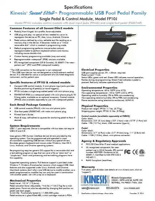
Electrical PropertiesUSB port supplies power, 5V, <30mA required. Pedal current ~1mA.Status LEDs: green and red. Green LED indicates normal operation, flashes during re-programming. Green+red indicates a pedal is pressed. Red-only indicates operational fault. Environmental PropertiesOperating temperature: 40 to 105°F (4 to 41°C).Non-operating temperature: -10 to 120°F (-23 to 49°C). Operating relative humidity: 5% to 90% non-condensing. Non-operating relative humidity: 0% to 95% non-condensing. Flame resistance rating (electronics enclosure): UL94V-0.Physical PropertiesProduct net weight, FP10J: 1.7 lbs. (0.77kg). Shipping gross weight, FP10J: 2.1lbs. (0.96kg). Control module (available separately at FSMJ2): Color: black.Dimensions: 2.0” (5.1cm) deep x 5.5” (14cm) wide x 0.75” (1.9cm) tall. Cable: ~9ft (~2.7m), black, USB connector (type A). Color: black.Dimensions: 2.7” (6.9cm) wide x 3.7” (9.4cm) long, 1.1” (2.8cm) tall.Two years, parts & labor (see details at , click on SpecificationsKinesis ®™Programmable USB Foot Pedal FamilySingle Pedal & Control Module, Model FP10JModel FP10J i ncludes control module with dual input jacks (FPMJ2) and single foot pedal (FS007MP) FP10JOptional Accessories#∙ Extra pedal (FS007MP): 10ft black cable, mini-phono plug, IPX1 rated.∙ Extra waterproof pedal (FS007MP-IPX8): IPX8 rated, 10ft black cable, mini-phono plug (note: mini -phono connection to control module is not waterproof).∙ Optional hand trigger (FS002HT8): 8 ft beige cable, mini-phono plug, IPX1 rated.∙ Pedal extension cables, mini-phono: Inquire (long lengths are possible).#Extra pedals and hand trigger require jack-equipped model.。
YJQ型液压加速器使用说明书INSTRUCTION MANUAL贵州高峰机械厂GUIZHOU GAOFENG MACHINERY FACTORYYJQ型液压加速器使用说明书1 概述和用途YJQ型液压加速器是为液压上击器增加震击功能而设计的井下打捞震击工具。
因此它必须和CSJ型超级震击器或YSJ型液压上击器联合使用。
工作时能对接在其下方的钻铤和上击器上部起加速作用,以获得对卡点更强大的震击力,同时可以减少震击之后钻柱回弹时的震动。
2 基本结构YJQ型液压加速器基本结构如图1所示。
心轴与缸套之间充满了具有高压缩指数的二甲基硅油。
心轴有花键与上缸套下端的花键相嵌合,这样不论是在打开,还是撞击位置都可以传递扭矩。
密封总成包括盘根和盘根压圈。
它安装于震击垫与导向杆之间,形成一个滑动密封副,工作时能使缸内产生高压。
3 工作原理钻具上提,钻具伸长,加速器的密封总成向上移动,硅油被压缩,象弹簧被压缩一样,硅油中贮存了能量(图2a)时,尤如一根上下二端拉紧的橡皮筋,下端突然释放,橡皮筋会迅速地弹上去一样,伸长的钻具回复使加速器下部以及接在其下方的钻铤和上击器上部就一起向上运动,与此同时加速器内腔的硅油贮存的能量也被突然释放,给运动着的钻铤和上击器的上部一个极大的加速度(图2b)。
当上击器到达冲程终点时,一个向上的巨大撞击力直接打击在落鱼上,此时加速器处于关闭状态(图2c)。
一次震击就告结束。
4 操作参照CSJ型超级震击器和YSJ型液压上击器使用说明书。
5 拆卸和装配加速器经多次使用或在恶劣条件下使用后,应送管子站全部拆开、清洗、检查。
拆卸和装配加速器应在井下工具液压拆装工作台上进行。
5.1 拆卸1)拆卸前要清除加速器内外表面上的泥沙和尘土。
2)用液压拆装工作台的钳口夹住中缸套(注意不要损坏油堵孔),拧松并卸下下接头。
流出的硅油盛入事先准备好的干净容器里。
3)用管钳夹紧导向杆末端的扳手位置,拧松导向杆。
4)用液压拆装工作台的钳口夹紧上缸套,拧松并旋转卸下中缸套。
CM4NANO用户手册上海晶珩电子科技有限公司2023-01-04版权声明CM4 Nano及其相关知识产权为上海晶珩电子科技有限公司所有。
上海晶珩电子科技有限公司拥有本文件的版权并保留所有权利。
未经上海晶珩电子科技有限公司的书面许可,不得以任何方式和形式修改、分发或复制本文件的任何部分。
免责声明上海晶珩电子科技有限公司不保证本硬件手册中的信息是最新的、正确的、完整的或高质量的。
上海晶珩电子科技有限公司也不对这些信息的进一步使用作出保证。
如果由于使用或不使用本硬件手册中的信息,或由于使用错误或不完整的信息而造成的物质或非物质相关损失,只要没有证明是上海晶珩电子科技有限公司的故意或过失,就可以免除对上海晶珩电子科技有限公司的责任索赔。
上海晶珩电子科技有限公司明确保留对本硬件手册的内容或部分内容进行修改或补充的权利,无需特别通知。
修订记录目录1产品概述 (6)1.1目标应用 (6)1.2规格参数 (6)1.3系统框图 (7)1.4功能布局 (8)1.5包装清单 (8)1.6订购编码 (8)2快速启动 (9)2.1设备清单 (9)2.2硬件连接 (9)2.3首次启动 (9)2.3.1Raspberry Pi OS (Desktop) (9)2.3.2Raspberry Pi OS (Lite) (12)2.3.3使能SSH功能 (14)2.3.4查找设备IP (14)3接线指南 (14)3.1Panel I/O (15)3.1.1BOOT (15)3.1.2micro-SD Card (15)3.2Internal I/O (15)3.2.1HDMI FPC (15)3.2.2MIPI DSI (16)4软件操作指引 (17)4.1USB 2.0 (17)4.1.1查看USB设备信息 (17)4.1.2USB存储设备挂载 (17)4.2以太网配置 (19)4.2.1千兆以太网 (19)4.2.2使用Network Manager工具配置 (19)4.2.3使用dhcpcd工具配置 (21)4.3WiFi (21)4.3.1使能WiFi功能 (21)4.3.2外置天线/内置PCB天线 (22)4.3.3AP及桥接模式 (22)4.4蓝牙 (22)4.4.1基本用法 (22)4.4.2示例 (23)4.5RTC (24)4.6LED指示 (25)4.7Buzzer (25)4.8串口通信 (25)4.8.1安装picocom工具 (25)4.8.2Debug UART (26)5操作系统安装 (27)5.1镜像下载 (27)5.2eMMC烧录 (28)5.2.1工具下载 (28)5.2.2烧录 (28)5.3基于原版Raspberry Pi OS在线安装BSP (29)6故障排除 (29)7FAQ (29)7.1.1默认用户名密码 (29)8关于我们 (30)8.1关于EDATEC (30)8.2联系方式 (30)1CM4 Nano是一款基于树莓派CM4的面向工业应用场景的计算机。
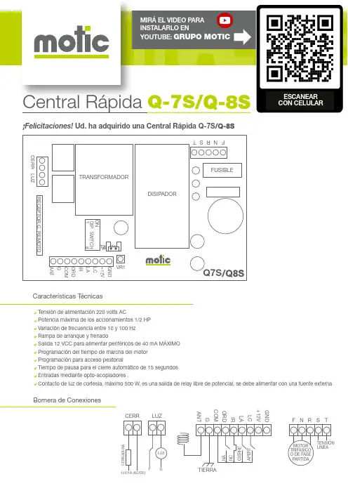
Central Rápida Q-7S¡Felicitaciones! Ud. ha adquirido una Central Rápida Q-7SESCANEAR CON CELULAR Características TécnicasTensión de alimentación 220 volts ACPotencia máxima de los accionamientos 1/2 HPVariación de frecuencia entre 10 y 100 HzRampa de arranque y frenadoSalida 12 VCC para alimentar periféricos de 40 mA MÁXIMOProgramación del tiempo de marcha del motorProgramación para acceso peatonalTiempo de pausa para el cierre automático de 15 segundosEntradas mediante opto-acopladores .Contacto de luz de cortesía, máximo 500 W, es una salida de relay libre de potencial, se debe alimentar con una fuente externa Bornera de ConexionesGND +12V LC LA IR ORD COM GANT CERR LUZ MIRÁ EL VIDEO PARAINSTALARLO ENYOUTUBE: GRUPO MOTICPaso 1 Conexión del Motor y Central Paso 2 Conexión de Accesorios OpcionalesFinales de Carrera (Recomendado)Para ello, liberar el eje del motor y abrir y cerrar manualmente el portón, con lo cual:*Se debe encender LdC cuando el portón está cerrado y apagarse cuando se empieza a abrir.** Se debe encender LdA cuando el portón está abierto y apagarse cuando se empieza a cerrar.En el caso en que se enciendan invertidos, invertir los cables LA y LC en la bornera.En caso de que LdA o LdC no enciendan o lo hagan intermitentemente, revise las conexiones y el Barrera Infrarroja (Opcional)Si no se emplea barrera infrarroja, dejar el Jumper "IR"colocado en la placa.Si se emplea barrera infrarroja, retirar el Jumper "IR" dela placa. Si la barrera infrarroja se activa durante el cierre,el motor se detiene y se vuelve a abrir.Electrocerradura (Opcional)Tener en cuenta que la central no permite alimentar unaelectrocerradura, es solo una salida de relay, por lo quese debe alimentar con fuente externa .Dejar el portón entreabierto y cortar la energía. Al habilitar laenergía nuevamente, al dar una orden con el pulsador o control,debe ABRIR. En caso de que CIERRE, invertir el sentido de girodel motor para corregirlo:Motor Trifásico: En caso de sentido de giro incorrecto,intercambiar los cables de motor S y T.Motor Fase Partida: En este caso, R es el común del motor.EN ESTA CENTRAL,¡LOS MOTORES JAMÁS DEBEN LLEVAR CAPACITOR!En caso de sentido de giro incorrecto, intercambiar los cables Sy T T G S M R NF 220VACTIERRA (JABALINA)T G S M R COMÚN N F 220VACTIERRA(JABALINA)GND +12V LC IR LA ORDCOM G ANT LdA LdC GND +12V LC IR LA ORDCOMCERR FUENTE EXTERNA 12V 1ARxProgramación de funciones mediante los dip switchLuz (Opcional)Botón de Orden (Opcional)LUZ LUZ 220V NF+12GND LUZLUZConexión de Led 12VccConexión de Lámpara 220 VAC pulsador NA GND+12V ORD LC LAProgramación de la apertura vehicularEsto le permitirá abrir el portón parcialmente para el paso peatonal por un tiempo de 10 segundos, tras lo cual se cerrará automáticamente, excepto que la barrera infrarroja esté interrumpida.Programación de los Controles Remotos para el Paso Peatonal1.Pulsar el botón T2, se encenderá el led Ld1.Programación de los Tiempos de Recorrido para apertura vehicularProgramación de apertura peatonal1/ BORRAR todos los controles.Mantener pulsar el botón T2por 6 segundos.El LED pr1 destellarávarias veces dando por T1T2LEDPR12/ GRABADO de los controles.Pulsar el botón T2 El LED pr1 quedaráencendido Si quiere grabarmás controlessiga pulsandolos botones delos controles Si terminó vuelva a pulsar el botón T2. El led pr1 se apagaráRecuerde que la electrónica sólo guarda en su memoria 60 electrónica no permite eliminar sólo un botón (eliminaratodos los controles).Pulsar el botón que quieragrabar T1T2T1T2LEDPR1El led PR1destellaráindicando el grabado del boton deseadoa/ Programación del tiempo del recorrido (sin decelere DIP Nº5 ON).Dejar el portón amitad del recorrido El LED pr1 se va a encender y al soltarlo, el portóncomenzará a cerrar Mantener pulsado elbotón T1 por 6”El portón cerraráy comenzará a abrir solo El portón volverá a cerrar dando porel programado T1T2nalizado el procedimiento 1Programación de los Tiempos de Recorrido para el Paso Peatonal CON FINALES DE CARRERAMOTIC Recomienda elegir los siguientes botones en cada control:Paso Total Paso Peatonal6.Ajuste de la velocidad del motorCon esta función, puede ajustar la velocidad del motor a gusto.Para aumentar la velocidad girar VR1 en sentido horario.Para disminuir la velocidad girar VR1 en sentido anti-horario.GND+12V LC LA IR ORD COM G ANT VR1IRPulsar el botón T2 El LED pr1 quedaráencendido Si quiere grabar más controles siga pulsandolos botones delos controles Si terminó suelte el boton T1,y pulse el boton T2.El led Ld1 se apagaráRecuerde que la electrónica sólo guarda en su memoria 60 electrónica no permite eliminar sólo un botón (eliminara todos los controles).Mantener pulsadoel botón T1 T1T2T1T2LED PR1El led PR1destellaráindicando elgrabado delboton deseado T1T2Pulsar el botón que quiera grabar Dejar el portón amitad del recorrido El portón se cierraautomáticamentey naliza la programaciónEl LED pr1 se va a encender y al soltarlo, el portón comenzará a cerrar hasta pisar el límite de cierre, luego abriráMantener pulsar el Antes de que el portón abra por completo,dar una orden con el botón del control remoto grabado donde se quiera iniciar el paso peatonalbotón T1 por 6”T1T2/ Mantenga alejados los controles y cables del alcance de niños y mascotas. El portón podría accionarse accidentalmente o sufrir lesiones./ Siempre corte el suministro eléctrico antes de operar manualmente el portón o realizar tareas de limpieza./ Evite aproximarse o caminar a través del portón. Su activación puede ocasionar accidentes./ Examine con frecuencia la instalación en busca de signos de desgaste o daño en los cables. Póngase en contacto con perso-nal autorizado en caso necesario.La garantía de los elementos o servicios vendidos por Grupo Motic SRL , (en adelante Motic ) aplica solo a los productos La garantía se reduce al reemplazo del producto defectuoso o a la reparación del mismo, dentro de un plazo de 10 días (dependiendo de la existencia de repuestos), a elección de Motic y a su solo criterio, no cubriendo las conse-cuencias ni costos ni daños emergentes ni daños contingentes que hubiera podido provocar o serles atribuidas a la falla.La garantía abarca única y explícitamente desperfectos de fabricación del equipo que no se encuentren relaciona-dos a errores en su aplicación, instalación, su uso en condiciones anormales o condiciones ambientales o meteo-rológicas extremas.La garantía se brinda en las instalaciones técnicas de Motic (su Domicilio Comercial) por lo que los equipos deben-dos o autorizados.Esta Garantía es Limitada y está sujeta a las condiciones y legislación vigente en la República Argentina,Para cualquier solicitud de cobertura de la Garantía, Reparaciones o Repuestos o cuestiones técnicas comunicar-se con Motic en Agüero 449, Teléfono (011) 4730-3222 en Villa Martelli (1603) Buenos Aires, Argentina. Este equipo está diseñado para uso residencial y no comercial, industrial o de alta demanda.Modelo de Equipo:Fecha de Compra: Lugar de Compra:Número de Factura de Compra:Número de Serie:garantíaPlazo de la Garantía para los motorreductores es de 2 (Dos) años a partir de la fecha de la factura. Las Controladoras electrónicas tienen 1 (Uno) año de garantía, los controles remotos 6 (Seis) meses, las pilas y otros consumibles no tienen garantía.。

NVIDIA L4 GPU Accelerator Product BriefDocument HistoryPB-11316-001_v01Version Date Authors Description of Change 01 March 9, 2023 AV, SM Initial releaseTable of ContentsOverview (1)Specifications (2)Product Specifications (2)Environmental and Reliability Specifications (4)Airflow Direction Support (5)Product Features (6)PCI Express Interface Specifications (6)PCIe Support (6)Single Root I/O Virtualization Support (6)Interrupt Messaging (6)Polarity Inversion and Lane Reversal Support (7)Root of Trust (7)Form Factor (7)Hockey Stick Board Retention (9)Support Information (10)Certifications (10)Agencies (10)Languages (11)List of FiguresFigure 1.NVIDIA L4 NVFF 5.5 HHHL with Full Height Bracket (1)Figure 2.NVIDIA L4 Airflow Direction (5)Figure 3.NVIDIA L4 PCIe Card Dimensions with Full Height Bracket (8)Figure 4.NVIDIA L4 PCIe Card Dimensions with Low Profile Bracket (8)Figure 5.NVIDIA L4 Hockey Stick Tab (9)List of TablesTable 1.Product Specifications (2)Table 2.Memory Specifications (3)Table 3.Software Specifications (3)Table 4.Board Environmental and Reliability Specifications (4)Table nguages Supported (11)OverviewThe NVIDIA L4 Tensor Core GPU delivers a versatile platform to accelerate Deep Learning, Graphics and Video processing applications in the Cloud and at the Edge. It is a half-height (low profile), half-length, single slot card featuring 24 GB of GDDR6 memory, x16 PCIe Gen4 connectivity at a 72 W maximum power envelope. It is a passively cooled card with a superior thermal design-requiring system airflow to operate and handles challenging ambient environments with ease (NEBS-3 capable).Powered by the NVIDIA Ada Lovelace architecture, L4 provides revolutionary multi-precision performance to accelerate deep learning and machine learning training and inference, video transcoding, AI audio (AU) and video effects, rendering, data analytics, virtual workstations, virtual desktop, and many other workloads.As part of NVIDIA AI, the L4 supports all AI frameworks and neural network models, delivering dramatic performance and efficiency that maximizes the utility of at-scale deployments.Figure 1. NVIDIA L4 NVFF 5.5 HHHL with Full Height BracketSpecificationsProduct SpecificationsTable 1 through Table 3 the product, memory, and software specifications for the NVIDIA L4 PCIe card.Table 1. Product SpecificationsSpecification NVIDIA L4Product SKU PG193 SKU 200NVPN: 699-2G193-0200-xxxTotal board power 72 W default72 W maximum40 W minimumThermal solution PassiveMechanical form factor HHHL-SS (half-height, half-length, single-slot) PCI Device IDs Device ID: 0x27B8Vendor ID: 0x10DESub-Vendor ID: 0x10DESub-System ID: 0x16CAFour-part ID (VID:DEVID:SVID:SSID)110DE:27B8:10DE:16CAGPU clocks Base: 795 MHzBoost: 2,040 MHzVBIOS EEPROM size: 16 MbitUEFI: SupportedDrivers Linux: R525 or laterWindows: R525 or laterPCI Express interface Physical x16 PCIe lanesPCIe Gen4 x16, x8; Gen3 x16Lane and polarity reversal supported Performance states P0, P8Zero Power Not supportedSpecification NVIDIA L4Weight Board: 270 Grams (excluding bracket)Bracket (Full height) with screws: 14 GramsBracket (Half height) with screws: 9 GramsNote:1The NVIDIA L4 is uniquely identified by its complete four-part ID.Table 2. Memory SpecificationsSpecification DescriptionMemory clock 6,251 MHzMemory type GDDR6Memory size 24 GBMemory bus width 192 bitsPeak memory bandwidth 300 GB/secTable 3. Software SpecificationsSpecification NVIDIA L4SR-IOV support Supported: 32 VF (virtual functions)BAR address (physical function) BAR0: 16 MiB1BAR1: 32 GiB1BAR3: 32 MiB1BAR address (virtual function) BAR0: 8 MiB (256 KiB per VF)1BAR1: 64 GiB, 64-bit (2 GiB per VF)1BAR3: 1 GiB, 64-bit (32 MiB per VF)1Message signaled interrupts MSI-X: SupportedMSI: Not supportedARI Forwarding SupportedSecure Boot Supported (See “Root of Trust” section)NVIDIA® CUDA® support CUDA 12.0 or laterVirtual GPU software support Supports vGPU 15.2 or laterPCI class code 0x03 – Display controllerPCI sub-class code 0x02 – 3D controllerECC support Enabled (by default); can be disabled using software SMBus (8-bit address) 0x9E (write), 0x9F (read)IPMI FRU EEPROM I2C address 0x50 (7-bit), 0xA0 (8-bit)Reserved I2C addresses 0xA0, 0xAA, 0xACSMBus direct access SupportedSpecification NVIDIA L4SMBPBI (SMBus Post-Box Interface) SupportedNote:1The KiB, MiB, and GiB notations emphasize the “power of two” nature of the values. Thus,>256 KiB = 256 × 1024>16 MiB = 16 × 10242>64 GiB = 64 × 10243Environmental and Reliability Specifications Table 4 provides the environment conditions specifications for the L4 PCIe card.Table 4. Board Environmental and Reliability SpecificationsSpecification DescriptionAmbient operating temperature 0°C to 50°CAmbient operating temperature (short term)1-5°C to 55°CStorage temperature -40°C to 75°COperating humidity (short term)15% to 93% relative humidityOperating humidity 5% to 85% relative humidityStorage humidity 5% to 95% relative humidityMean time between failures (MTBF) Uncontrolled environment:2 2,147,604 hours at 35°CControlled environment:3 2,785,669 hours at 35°C Notes: Specifications in this table are applicable up to 6,000 feet.1A period not more than 96 hours consecutive, not to exceed 15 days per year.2Some environmental stress with limited maintenance (GF35).3No environmental stress with optimum operation and maintenance (GB35).Airflow Direction SupportThe NVIDIA L4 PCIe card employs a bidirectional heat sink, which accepts airflow either left-to-right or right-to-left directions.Figure 2. NVIDIA L4 Airflow DirectionProduct FeaturesPCI Express Interface SpecificationsThe following subsections describe the PCIe interface specifications for the L4 PCIe card.PCIe SupportThe L4 card supports PCIe Gen4. Gen4 x16 interface should be used when connecting to the L4 PCIe card.Single Root I/O Virtualization SupportSingle Root I/O (SR-IOV) Virtualization is a PCIe specification that allows a physical PCIe device to appear as multiple physical PCIe devices. Per PCIe specification, each device can have up to a maximum of 256 virtual functions (VFs). The actual number can depend on the device. SR-IOV is enabled in L4 PCIe card. The number of VFs supported is given in Table 3.For each device, SR-IOV identifies two function classes:>Physical functions (PFs) constitute full-featured functionality. They are fully configurable, and their configuration can control the entire device. Naturally, a PF also has full ability to move data in and out of the device.>Virtual functions (VFs), which lack configuration resources. VFs exist on an underlying PF, which may support many such VFs. VFs can only move data in and out of the device; they cannot be configured and cannot be treated like a full PCIe device.The OS or hypervisor instance must be aware that they are not full PCIe devices. The L4 requires that SBIOS and software support in the OS instance or hypervisor is configured to enable support SR-IOV. The OS instance or hypervisor must be able to detect and initialize PFs and VFs.Interrupt MessagingThe L4 PCIe card only supports the MSI-X interrupt messaging protocol. The MSI interrupt protocol is not supported.Polarity Inversion and Lane Reversal SupportLane Polarity Inversion, as defined in the PCIe specification, is supported on the L4 PCIe card.Lane Reversal, as defined in the PCIe specification, is supported on the L4 PCIe card. When reversing the order of the PCIe lanes, the order of both the Rx lanes and the Tx lanes must be reversed.Root of TrustThe NVIDIA L4 provides a primary root of trust within the GPU that provides the following:>Secure boot>Secure firmware upgrade>Firmware rollback protection>Support for in-band firmware update disable (established after each GPU reset)>Secure application processor recoveryForm FactorThe NVIDIA L4 PCIe card conforms to NVIDIA Form Factor 5.5 specification for a half-height (low profile) half-length (HHHL) single slot PCIe card. For details refer to the NVIDIA Form Factor 5.5 for Enterprise PCIe Products Specification (NVOnline reference number 106337).In this product brief, nominal dimensions are shown.Figure 3. NVIDIA L4 PCIe Card Dimensions with Full Height BracketFigure 4. NVIDIA L4 PCIe Card Dimensions with Low Profile BracketHockey Stick Board RetentionThe NVDIA L4 enables south edge board retention using a “hockey stick” tab located to the east of the PCIe card fingers, as shown in Figure 5.Figure 5. NVIDIA L4 Hockey Stick TabSupport InformationCertifications>Windows Hardware Quality Lab (WHQL):•Windows 10, Windows 11•Windows Server 2019, Windows Server 2022>Ergonomic requirements for office work W/VDTs (ISO 9241)>EU Reduction of Hazardous Substances (EU RoHS)>Joint Industry guide (J-STD) / Registration, Evaluation, Authorization, and Restriction of Chemical Substance (EU) – (JIG / REACH)>Halogen Free (HF)>EU Waste Electrical and Electronic Equipment (WEEE)Agencies>Australian Communications and Media Authority and New Zealand Radio Spectrum Management (RCM)>Bureau of Standards, Metrology, and Inspection (BSMI)>Conformité Européenne (CE)>Federal Communications Commission (FCC)>Industry Canada - Interference-Causing Equipment Standard (ICES)>Korean Communications Commission (KCC)>Underwriters Laboratories (cUL, UL)>Voluntary Control Council for Interference (VCCI)Support Information LanguagesTable 5. Languages SupportedLanguages Windows1LinuxEnglish (US) Yes YesEnglish (UK) Yes YesArabic YesChinese, Simplified YesChinese, Traditional YesCzech YesDanish YesDutch YesFinnish YesFrench (European) YesGerman YesGreek YesHebrew YesHungarian YesItalian YesJapanese YesKorean YesNorwegian YesPolish YesPortuguese (Brazil) YesPortuguese (European/Iberian) YesRussian YesSlovak YesSlovenian YesSpanish (European) YesSpanish (Latin America) YesSwedish YesThai YesTurkish YesNote:1Microsoft Windows 10, Windows 11, Windows Server 2019, and Windows Server 2022 Windowsare supported.NVIDIA Corporation | 2788 San Tomas Expressway, Santa Clara, CA 95051NoticeThis document is provided for information purposes only and shall not be regarded as a warranty of a certain functionality, condition, or quality of a product. NVIDIA Corporation (“NVIDIA”) makes no representations or warranties, expressed or implied, as to the accuracy or completeness of the information contained in this document and assumes no responsibility for any errors contained herein. NVIDIA shall have no liability for the consequences or use of such information or for any infringement of patents or other rights of third parties that may result from its use. This document is not a commitment to develop, release, or deliver any Material (defined below), code, or functionality.NVIDIA reserves the right to make corrections, modifications, enhancements, improvements, and any other changes to this document, at any time without notice.Customer should obtain the latest relevant information before placing orders and should verify that such information is current and complete. NVIDIA products are sold subject to the NVIDIA standard terms and conditions of sale supplied at the time of order acknowledgement, unless otherwise agreed in an individual sales agreement signed by authorized representatives of NVIDIA and customer (“Terms of Sale”). NVIDIA hereby expressly objects to applying any customer general terms and conditions with regards to the purchase of the NVIDIA product referenced in this document. No contractual obligations are formed either directly or indirectly by this document.NVIDIA products are not designed, authorized, or warranted to be suitable for use in medical, military, aircraft, space, or life support equipment, nor in applications where failure or malfunction of the NVIDIA product can reasonably be expected to result in personal injury, death, or property or environmental damage. NVIDIA accepts no liability for inclusion and/or use of NVIDIA products in such equipment or applications and therefore such inclusion and/or use is at customer’s own risk.NVIDIA makes no representation or warranty that products based on this document will be suitable for any specified use. Testing of all parameters of each product is not necessarily performed by NVIDIA. It is customer’s sole responsibility to evaluate and determine the applicability of any information contained in this document, ensure the product is suitable and fit for the application planned by customer, and perform the necessary testing for the application in order to avoid a default of the application or the product. Weaknesses in customer’s product designs may affect the quality and reliability of the NVIDIA product and may result in additional or different conditions and/or requirements beyond those contained in this document. NVIDIA accepts no liability related to any default, damage, costs, or problem which may be based on or attributable to: (i) the use of the NVIDIA product in any manner that is contrary to this document or (ii) customer product designs.No license, either expressed or implied, is granted under any NVIDIA patent right, copyright, or other NVIDIA intellectual property right under this document. Information published by NVIDIA regarding third-party products or services does not constitute a license from NVIDIA to use such products or services or a warranty or endorsement thereof. Use of such information may require a license from a third party under the patents or other intellectual property rights of the third party, or a license from NVIDIA under the patents or other intellectual property rights of NVIDIA.Reproduction of information in this document is permissible only if approved in advance by NVIDIA in writing, reproduced without alteration and in full compliance with all applicable export laws and regulations, and accompanied by all associated conditions, limitations, and notices. THIS DOCUMENT AND ALL NVIDIA DESIGN SPECIFICATIONS, REFERENCE BOARDS, FILES, DRAWINGS, DIAGNOSTICS, LISTS, AND OTHER DOCUMENTS (TOGETHER AND SEPARATELY, “MATERIALS”) ARE BEING PROVIDED “AS IS.” NVIDIA MAKES NO WARRANTIES, EXPRESSED, IMPLIED, STATUTORY, OR OTHERWISE WITH RESPECT TO THE MATERIALS, AND EXPRESSLY DISCLAIMS ALL IMPLIED WARRANTIES OF NONINFRINGEMENT, MERCHANTABILITY, AND FITNESS FOR A PARTICULAR PURPOSE. TO THE EXTENT NOT PROHIBITED BY LAW, IN NO EVENT WILL NVIDIA BE LIABLE FOR ANY DAMAGES, INCLUDING WITHOUT LIMITATION ANY DIRECT, INDIRECT, SPECIAL, INCIDENTAL, PUNITIVE, OR CONSEQUENTIAL DAMAGES, HOWEVER CAUSED AND REGARDLESS OF THE THEORY OF LIABILITY, ARISING OUT OF ANY USE OF THIS DOCUMENT, EVEN IF NVIDIA HAS BEEN ADVISED OF THE POSSIBILITY OF SUCH DAMAGES. Notwithstanding any damages that customer might incur for any reason whatsoever, NVIDIA’s aggregate and cumulative liability towards customer for the products described herein shall be limited in accordance with the Terms of Sale for the product.TrademarksNVIDIA, the NVIDIA logo, CUDA, NVIDIA-Certified System, and NVIDIA GPU Boost are trademarks and/or registered trademarks of NVIDIA Corporation in the U.S. and other countries. Other company and product names may be trademarks of the respective companies with which they are associated.Copyright© 2023 NVIDIA Corporation. All rights reserved.。
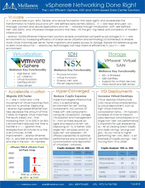
Accelerate vMotionMigrate 23X FasterHyper-ConvergedvSphere ®Networking Done RightThe Most Efficient vSphere, NSX and VSAN-based Data Center Solutionsz VirtualizationSDNStorageMellanox Key FunctionalityMellanox Key FunctionalityMellanox Key Functionality•High Bandwidth •Low Latency •Virtual Functions •Certified SR-IOV •Inbox drivers•Physical Function •Virtual Functions •Overlay Networks •Proven deployments•RDMA Enabled •iSER Certified•Support for All-Flash devices •Inbox RoCE and iSER driversVMwareVMware provides a powerful, flexible, and secure foundation that adds agility and accelerates thetransformation to hybrid cloud and software defined data centers (SDDC). VMware helps end-users run, manage, connect and secure applications and new workloads through virtualization, Software DefinedNetworks (SDN), and virtualized storage solutions that help with the growing needs and complexity of modern infrastructure.Mellanox 10/25G Ethernet interconnect solutions enable unmatched competitive advantages in VMware environments by increasing efficiency of overall server utilization and eliminating I/O bottleneck to enable more virtual machines per server, faster migrations and speed access to storage. Explore this reference guide to learn more about how Mellanox key technologies can help improve efficiencies in your VMware environment.VMware vMotion allows themovement of virtual machines from one host to another. Deploying Mellanox high-speed Ethernet can help decrease the amount of time it takes to migrate virtual machines. The results clearly show thatincreasing from 10 to 25G in an ESXi 6 environment reduced the time to transfer a VM. Migration timedropped from 55 minutes to a little over 2 minutes, a 96%improvement. Mellanox Ethernet, RDMA, and iSER drivers are certified and ship in the box with vSphere.Reduce CapEx ExpenseVDI DeploymentsIncrease Virtual DesktopsVirtual desktop infrastructure (VDI) have similar characteristics as cloud deployment, such as high virtual machineconsolidation ratios, with typically hundreds of small to mediumsized desktops consolidated on a single host. Network performance is important for user experience as well as yielding direct CapEx and OpEx savings. Savings can grow as you move to higherperforming networks. Below is an example of CapEx savings when moving from 10 to 25GE.Hyper-Converged Infrastructure (HCI) is a demandingenvironment for networking components. HCI consists of three software components: compute virtualization, storage virtualization and management in which all three require an agile and responsive network. Deploying on 10, or better, 25G larger network pipes assists as does network adapters with offload capabilities to optimize performance and availability of synchronization and replication of virtualized workloads.CapEx Analysis: 10G vs. 25GCapEx Analysis: 10G vs. 25GScalable from a half rack to multiple racksHalf Rack 12 nodesFull Rack 24 nodesPay As You Grow10 Racks up to 240 nodesDeployment Config134411GbE link: 1GbE Transceiver125/10GbE link: QSFP to SFP+324100GbE link: QSFP to QSFP 100/40GbE link: QSFP to QSFP Why Spectrum▪ 2 switches in 1U▪Ideal storage/HCI port counts▪Zero packet loss ▪Low latency▪RoCE optimized (NVMe-oF, Spark, SMB Direct, etc.)▪NEO for network automation/visibility▪Native SDK for containers ▪Cost optimized▪Network OS alternativesProvisioning & Orchestration▪Zero-touch provisioning ▪VLAN auto-provisioning▪Migrate VMs without manual configuration▪VXLAN/DCI support for VM migration across multiple datacenters for DRMonitoring▪Performance monitoring ▪Health monitoring ▪Detailed telemetry▪Alerts and notificationsAutomated Network▪½ 19” width, 1U height ▪18x10/25GbE + 4x40/100GbE ▪57W typical (ATIS)2Spectrum SwitchesProven Higher EfficiencyIncreasing VMware EfficiencyNSX services enable east-west routing between the SDDC and north-south routing for external networks and require VXLAN segmentation which can consume CPU processes and diminish overall server efficiency. Mellanox supports VXLAN offloads to handle this processing resulting in higher throughput and over 50% reduction in CPU utilization.Accelerate NSXStorage virtualization requires an agile and responsive network. iSER accelerates workloads by using an iSCSI extensions for RDMA. Using the iSER extension lowers latencies and CPU utilization to help keep pace with I/O requirements and provides a 70% improvement in throughput and 70% reduction in latencies.VMware EVO SDDC provides a validated suite of interoperable, tested components to deliver a completely Integrated System. This comprises fully qualifiedhardware components including Mellanox switches and adapters that are pre-built and pre-racked, providing an appliance-likeexperience that makes it easy for customers to deploy, operate and support. Mellanox leverages our relationship with Cumulus Linux to extend access from Layer 2 across Layer 3 networks topologies,Deliver 3X Efficiency with iSERFully Certified with EVOAverage CPU% per 1GbE VXLAN Traffic。
创新智造引领生命科技快速上手指南Quick Start Guide M G I T e c h C o ., L t d .仅供科研使用深圳华大智造科技有限公司Main Building and Second floor of No.11 Building, Beishan Industrial Zone, Yantian District, Shenzhen, 518083, Guangdong, China 中国深圳市盐田区北山工业区综合楼及11栋2楼网址/Website:***********************邮箱/E-mail:地址/Address:Research Use Only关于本指南本指南适用于MegaBOLT生信分析加速器,指南版本1.0,软件版本V2.1.0。
本指南及其包含的信息为深圳华大智造科技有限公司(以下简称深圳华大智造)的专有保密信息,未经深圳华大智造的书面许可,任何个人或组织不得全部或部分地对本指南进行重印、复制、修改、传播或公布给他人。
本指南的读者为终端用户,其作为设备的一部分,由深圳华大智造授权终端用户予以使用。
严禁未授权的个人使用本指南。
深圳华大智造对本指南不做任何种类的保证,包括(但不限于)用于特定目的的商业性和合理性的隐含保证。
深圳华大智造已经采取措施,确保本指南的准确性。
但是,深圳华大智造对错误或遗漏不承担责任,并保留任何对本指南和设备进行改进以提高其可靠性、功能或设计的权利。
本指南中的所有图片均为示意图,图片内容可能与实物有细微差异,请以购买的设备为准。
©2019 深圳华大智造科技有限公司版权所有。
发布日期:2019年11月8日制造商信息版本记录About this guideThis guide is applicable to MegaBOLT Bioinformatics Analysis Accelerator.The edition is 1.0 and the software version is V2.1.0.This guide and the information contained within are proprietary to MGI TechCo., Ltd. (hereinafter called MGI), and are intended solely for the contractualuse of its customer in connection with the use of the product described hereinand for no other purpose. Any person or organization can not entirely orpartially reprint, copy, revise, distribute or disclose to others the guide withoutthe prior written consent of MGI. Any unauthorized person should not use thisguide.MGI does not make any promise of this guide, including (but not limited to)any commercial of special purpose and any reasonable implied guarantee.MGI has taken measures to guarantee the correctness of this guide. However,MGI is not responsible for any mistakes or missing parts in the guide, andreserves the right to revise the guide and the software, so as to improve thereliability, performance or design.Figures in this guide are all illustrations. The contents might be slightlydifferent from the software, please refer to the software purchased.©2019 MGI Tech Co., Ltd. All rights reserved.Release date: November 8, 2019Manufacturer informationRevision history目录1快速开始 (1)硬件安装 (1)进入操作系统 (1)进入命令行终端 (2)查看帮助文档 (3)投递任务 (3)1使用ZLIMS (5)1MegaBOLT文档导航 (6)文档简介 (6)获取文档 (7)C o n t e n t s Contents1Quick start (9)Assembling the device �������������������������������������������������������������������������9Logging into the system ����������������������������������������������������������������������9Starting the terminal ���������������������������������������������������������������������������10Viewing Help ����������������������������������������������������������������������������������������11Submitting a task ��������������������������������������������������������������������������������11 1Working with ZLIMS ....................................................13 1MegaBOLT documents (14)Brief introduction ��������������������������������������������������������������������������������14Accessing the documents �����������������������������������������������������������������15快速开始1 快速开始硬件安装连接主机、显示器、键盘与鼠标,将加密锁插入任意USB 接口,接通电源,即可开机。
Copyright 2020 © Embedded Artists ABGet started with Google Coral M.2 and USB AcceleratorsEmbedded Artists ABJörgen Ankersgatan 12SE-211 45 MalmöSwedenhttps://Copyright 2020 © Embedded Artists AB. All rights reserved.No part of this publication may be reproduced, transmitted, transcribed, stored in a retrieval system, or translated into any language or computer language, in any form or by any means, electronic, mechanical, magnetic, optical, chemical, manual or otherwise, without the prior written permission of Embedded Artists AB.DisclaimerEmbedded Artists AB makes no representation or warranties with respect to the contents hereof and specifically disclaim any implied warranties or merchantability or fitness for any particular purpose. Information in this publication is subject to change without notice and does not represent a commitment on the part of Embedded Artists AB.FeedbackWe appreciate any feedback you may have for improvements on this document. Send your comments by using the contact form: /contact.TrademarksAll brand and product names mentioned herein are trademarks, services marks, registered trademarks, or registered service marks of their respective owners and should be treated as such.Table of Contents1Document Revision History (4)2Introduction (5)2.1Supported hardware (5)2.2Additional documentation (5)2.3Conventions (6)3Get started (7)3.1Setup hardware (7)3.1.1M.2 Accelerator (7)3.1.2USB Accelerator (7)3.2Download and flash pre-built Yocto image (8)3.3Enable PCIe support (9)3.3.1iMX8M COM board (9)3.3.2iMX8M Mini uCOM board (9)3.4Install Edge TPU runtime (9)3.5Install TensorFlow Lite (10)3.6Example: Image classification (10)3.6.1Run example (11)3.7Example: Image detection (13)3.7.1Run example (13)3.8Example: Camera (16)3.8.1Run classification example (17)3.8.2Run detection example (17)4Troubleshooting (19)4.1Cannot find libedgetpu.so.1 (19)4.2ValueError: Failed to load delegate from libedgetpu.so.1 (19)4.3Cannot identify device '/dev/video0' (19)5Yocto image (21)5.1Debian package manager (21)5.2Additional packages (21)1 Document Revision History2 IntroductionThis document provides you with step-by-step instructions for how to get stared with the Google Coral M.2 and/or USB accelerators on Embedded Artists iMX8 based COM boards.Coral is a technology from Google that accelerates the processing of TensorFlow models used with machine learning. At its core there is the Edge TPU coprocessor that executes neural networks at high speed. This coprocessor is available in multiple form factors such as the M.2 Accelerator with PCIe interface or USB accelerator.More information about Coral is available on the link below.https://coral.ai/technology/The models used by the examples in this document all come from https://coral.ai/models/ and can be divided into two categories:•Classification, where the model can recognize a set of objects and the demo scripts will print which (if any) objects are found and with what probability. Examples in 3.6 and 3.8.1 •Detection, where the model can recognize a set of objects and the demo scripts will draw a rectangle in the image/video around the detected object. Examples in 3.7 and 3.8.2It should be possible to run classification/detection using any of the models fromhttps://coral.ai/models/ but that is left as an exercise for the reader.2.1 Supported hardwareThe instructions in this document work wi th the following Developer’s Kits from Embedded Artists as the board needs to have a 64-bit core.•iMX8M Developer’s Kit V2 (EAK00330)•iMX8M Mini uCOM Developer’s Kit V2 (EAK00347)•iMX8M Nano uCOM Developer’s Kit V2 (EAK00360). Note: This board doesn’t support PCIe. You also need a Coral M.2 Accelerator with A+E key or a Coral USB Accelerator.https://coral.ai/products/m2-accelerator-ae/https:///new/google-coral/coral-m2-accelerator-ae/https://coral.ai/products/acceleratorhttps:///ProductDetail/Coral/G950-01456-01?qs=u16ybLDytRbcxxqFKdbhgQ%3D%3D2.2 Additional documentationAdditional documentation you might need is.•Working with Yocto to build Linux– found on Embedded Artists website.•How to use a Camera with an iMX Developer’s Kit – found on Embedded Artists website.•Getting started guide - https:///getting-started/•Get started documentation from Coral: https://coral.ai/docs/m2/get-started/2.3 ConventionsA number of conventions have been used throughout to help the reader better understand the content of the document.Constant width text– is used for file system paths and command, utility and tool names.3 Get started3.1 Setup hardware3.1.1 M.2 AcceleratorNote 1: You need a COM Carrier board V2 for these instructions.Note 2: The iMX8M Nano doesn’t have a PCIe interface. Use the USB accelerator instead.All you need to do is insert the Coral M.2 Accelerator to the M.2 E-key connector on the COM Carrier board V2 as shown in Figure 1.Figure 1 - M.2 Accelerator attached to COM Carrier board V23.1.2 USB AcceleratorFor iMX8M Mini uCOM and iMX8M Developer’s Kits you can connect the USB accelerator directly to USB Host Type A connector (J12) on the carrier board, see Figure 2.The iMX8M Nano uCOM only has one USB port which by default is connected to USB OTG connector (J11). You need a micro-B (male) to USB A (female) adapter similar to the one shown in Figure 3.It is possible to change a slider switch, S3:8, on the back of the uCOM adapter board and thereby connecting the USB port on the iMX8M Nano to the USB Host Type A connector (J12) on the carrier board. See section 7.2 in the iMX8M Nano uCOM datasheet for details.Note: If you want to try the camera related examples, described in section 3.8 together withthe iMX8M Nano you need to change the slider switch. The reason is both the acceleratorand the camera need a USB interface.Figure 2 - USB connectors on carrier boardFigure 3 - USB micro-B (male) to USB A (female) adapter3.2 Download and flash pre-built Yocto imageTo be able to setup and use Coral you need software (mostly Python packages) that is not normally installed on a standard ea-image-base distribution. Images with as many as possible of the needed packages have been prepared and are available on . Go to this website and download the zip file that ends with _coral.zip for the board you are using.Unpack this zip file on your computer and setup your iMX Developer’s Kit for OTG boot mod e (see the document Working with Yocto for details). Flash the full image by using UUU and thefull_tar.uuu script file.3.3 Enable PCIe supportReset the board and boot into the U-boot console. You need to hit any key on your keyboard to stop autoboot. Go to the section below that corresponds to the board you are using.3.3.1 iMX8M COM boardChange to the device tree file that enables PCIe support.3.3.2 iMX8M Mini uCOM boardChange to the device tree file that enables PCIe support.3.4 Install Edge TPU runtimeThe Edge TPU runtime is available as a Debian package. Support for Debian package manager has been added to the Yocto image, but you also have to add a Google repository so the package can be found.Update the package index.You will most likely get several errors while running update since the main package feed probably don’t exist. The prebuilt image from section 3.2 was created on a computer with IP address 192.168.1.11 and that is where apt-get will look for the package feed.You will also get warnings regarding the Google repository about it having an invalid signature. You can ignore this for now.Download and install the Edge TPU runtime environment. Enter ‘y’ to acknowledge that you want to install the package without verification. The warning comes as the signature of the Google repository is not known (could have been fixed by adding / using apt-key).3.5 Install TensorFlow LiteTensorFlow Lite is used to run machine learning models. Here we will install TensorFlow Lite for Python. There are different packages for different versions of Python and also for different platforms. The original instructions are available at the link below.https:///lite/guide/pythonThe Python version installed in the pre-built image for Linux 5.4.24 is 3.7 and for iMX8 based boards the platform is Linux (ARM 64):The Python version installed in the pre-built image for Linux 4.14.98 is 3.5 and for iMX8 based boards the platform is Linux (ARM 64):3.6 Example: Image classificationFollow the steps below to install example model that can be used to classify images of certain birds.Get started with Google Coral M.2 and USB Accelerators Page 11 # cd && mkdir -p coral && cd coral# git clone https:///google-coral/tflite.git# cd tflite/python/examples/classification# bash install_requirements.shThe last instruction will install the example’s dependencies. It will also download a photo of a Parrotthat will be classified.The downloaded model files include a text file containing a list of all the birds that the model canclassify.# less models/inat_bird_labels.txt0 Haemorhous cassinii (Cassin's Finch)1 Aramus guarauna (Limpkin)...3.6.1 Run exampleTo classify the parrot in Figure 4 run the instructions below.Figure 4 - Parrot that will be classified by the example modelFirst, we must make sure Python can find the Edge TPU library.# export LD_LIBRARY_PATH=/usr/lib/aarch64-linux-gnu/Now run the classify model on the Edge TPU. The script will run the model 5 times and the first time it will be a bit slower since it has to load the model into the Edge TPU memory.# python3 classify_image.py \--model models/mobilenet_v2_1.0_224_inat_bird_quant_edgetpu.tflite \--labels models/inat_bird_labels.txt \--input images/parrot.jpgTo get a sense of how much the Edge TPU accelerates the classification, you can also try to run this model directly on the processor to see the how much slower it is.Both runs above correctly detect the bird as an Ara macao with the same probability (77%) which is the expected result given that the input image and the model is the same. The accelerator does it about 50 times faster (2.9ms vs 147.2ms).We can also try to classify other images of birds. Try for example to download this image of a Rook.Get started with Google Coral M.2 and USB Accelerators Page 133.7 Example: Image detectionFollow the steps below to install an example model that can be used to detect objects in an image. The git repository is the same as in the previous example so if you have followed the instructions in 3.6then skip the git clone command below.# cd && mkdir -p coral && cd coral# git clone https:///google-coral/tflite.git# cd tflite/python/examples/detection# sed -i 's/mobilenet_ssd/ssd_mobilenet/g' install_requirements.sh# bash install_requirements.shThe sed command above will correct the name of the model. That error has been reported and fixedbut is not yet released. The last instruction will install the example’s dependencies. It will alsodownload a photo of Grace Hopper that will be used for image detection.The downloaded model files include a text file containing a list of all the objects that the model candetect.# less models/coco_labels.txt0 person1 bicycle2 car...3.7.1 Run exampleTo detect objects in Figure 5 run the instructions below.Figure 5 – Photo of Grace Hopper used by the example modelFirst, we must make sure Python can find the Edge TPU library.# export LD_LIBRARY_PATH=/usr/lib/aarch64-linux-gnu/Now run the classify model on the Edge TPU. The script will run the model 5 times and the first time it will be a bit slower since it has to load the model into the Edge TPU memory.To get a sense of how much the Edge TPU accelerates the detection, you can also try to run this model directly on the processor to see the how much slower it is.Both runs above correctly detect both the person and the tie in the image with the same probabilities (84%) but the accelerator does it about 20 times faster (15.43ms vs 312.41ms). Download the output image (grace_hopper_processed.bmp) to a PC to view it or, if you have a display connected use the framebuffer image viewer:# fbi –a -T 1 images/grace_hopper_processed.bmpNote 1: On Linux 4.14.98 using the image viewer breaks the desktop. Run the followingcommand after viewing the image to restart the desktop:#systemctl restart WestonNote 2: If nothing is shown on the display when running fbi this can be because of anunsupported resolution for the framebuffer. From within u-boot you can set the kernelparameter video like this# setenv extra_bootargs video=1280x720The image will look like this:Figure 6 –Processed photo of Grace Hopper showing the found “person” and “tie” objectsWe can also try to detect objects from the list in other images. Try for example to download this image of an apple and an orange.# curlhttps:///wikipedia/commons/thumb/a/a8/Apple_an d_Orange_-_they_do_not_compare.jpg/220px-Apple_and_Orange_-_they_do_not_compare.jpg --output images/ao.jpg# python3 detect_image.py \--model models/ssd_mobilenet_v2_coco_quant_postprocess_edgetpu.tflite \ --labels models/coco_labels.txt \--input images/ao.jpg \--output images/ao_processed.jpg----INFERENCE TIME----Note: The first inference is slow because it includes loading themodel into Edge TPU memory.53.10 ms16.93 ms15.12 ms16.69 ms15.81 ms-------RESULTS--------orangeid: 54score: 0.96484375bbox: BBox(xmin=109, ymin=29, xmax=213, ymax=134)appleid: 52score: 0.93359375bbox: BBox(xmin=41, ymin=18, xmax=121, ymax=105)Figure 7 – Image of apple and orange3.8 Example: CameraNote: For the iMX8M Nano you need to change a slider switch to be able to connect both the camera and the USB accelerator, see section 3.1.2 above.This example requires a camera (described in the document How to use a Camera with an iMX Developer’s Kit) and a display. The instructions in this document were tested on a Logitech QuickCam Pro USB camera and the Embedded Artists 7-inch HDMI Display Kit(https:///products/7-inch-hdmi-display-kit/) but any HDMI display should work.Follow the steps below to prepare the example that can be used to classify or detect objects in a live camera feed.The first sed command above is needed as the file system is using Wayland and not the X Window System. The second sed command prevents the gstreamer.py script from thinking that the iMX8M COM board is the Google Coral Dev Board.3.8.1 Run classification exampleFirst, we must make sure Python can find the Edge TPU library.Now run the classify model on the Edge TPU. It will take a couple of seconds to start and then the video feed should appear on the display. The console will print out what is foundStop the demo with Ctrl+C.To test without the Edge TPU:Note that the inference is 34 times slower without the acceleration (4.16 vs 141.43ms). With the accelerator the frame rate is limited by the camera’s capture rate to 15fps but without acceleration the inference time limits the frame rate to a maximum of 1000/141.43 = 7fps.3.8.2 Run detection exampleFirst, we must make sure Python can find the Edge TPU library.Now run the detect model on the Edge TPU. The script will take a couple of seconds to start and then the video feed should appear on the display. The console will only print out statisticsStop the demo with Ctrl+C.To test without the Edge TPU:Note that the inference is 20 times slower without the acceleration (15.62 vs 316.46ms). With the accelerator the frame rate is limited by the camera’s capture rate to 15fps but without acceleration the inference time limits the frame rate to a maximum of 1000/316.46 = 3fps.4 Troubleshooting4.1 Cannot find libedgetpu.so.1If you get an error message similar to below the most likely problem is that you have forgotten to set LD_LIBRARY_PATH as explained in section 3.6.1 above. You could also have forgot or failed to install the TPU Edge runtime library as explained in section 3.4 above.4.2 ValueError: Failed to load delegate from libedgetpu.so.1Error message:Reason 1:PCIe is not enabled. Please make sure you have followed the instructions in section 3.3 above. Reason 2:You could also get this error message if the M.2 A ccelerator isn’t inserted into the M.2 connector on the COM Carrier board V2.You can check if the M.2 Accelerator is detected on the PCI bus by using lspci.You should get a result similar to below.You can also check if the PCI driver (Apex) is loaded and available.4.3 Cannot identify device '/dev/video0'Error message:Reason 1:The camera is not connected. Check that the camera is connected correctly, reboot and test again Reason 2:The camera is not mapped as /dev/video0. Check which video device is in use:Use the found device when running the camera examples by passing the -videosrc parameter like this:5 Yocto imageThis chapter shows how the pre-built Yocto image has been created in case you need to build ityourself.5.1 Debian package managerSupport for the Debian package manager (apt) is needed in order to install the Edge TPU runtime.Do the following modifications to your conf/local.conf.Change package class from rpm to deb.Enable package-management.You can also set a default package feed. Replace the IP address below with your own.Add apt to the image.This program is added in IMAGE_INSTALL_append, see section 5.2 below.5.2 Additional packagesAlso make sure the following packages are added to your build.Copyright 2020 © Embedded Artists AB Rev A。
MFG321419-LBetter Machine Design with Inventor Design AcceleratorsThom TremblayConcepts and Design, LLCDescriptionSimulation technologies are very powerful, but for purchased fasteners or machine components that use standard gear tooth profiles, bearings, chains, or springs simulation aren’t the most efficient solutions. The answers to selecting those types of components have been cataloged for decades in handbooks and reference materials. In this course, we’ll get hands on to try out several of the Design Accelerators in Inventor that use time-tested performance standards to size and select components. These tools can also shorten the design process by creating multiple features at once even through multiple components in an assembly. If you design machinery, you need to be aware of these tools.SpeakerIn 1988 Thom Tremblay became convinced that a 3D model should be used as the primary way to create the 2D drawing he needed. The next several years working as a drafter and mechanical designer in shipbuilding, planning, casework, commercial electronics, and centrifugal compressors eventually led Thom using his skills to teach others. With over twenty years of experience consulting with businesses and education institutions of all types and sizes, Thom has developed an understanding of how people use and learn technologies. Thom also holds professional certifications in Autodesk AutoCAD and Autodesk Inventor, and is an Autodesk Certified Instructor - Gold. Thom has authored several books and online learning content on Autodesk Inventor and is authoring online learning content for Fusion 360.Design AcceleratorsDesign Accelerators are a standards-based tool for creating or calculating machine components based on the engineering requirements of the design. Each of the tools is either a Calculator which can give you the information on what is required of a machine component or a Generator which can based on basic input or calculators create the digital model of the standard component.Created in the context of an assembly, the Design Accelerator use your inputs to determine what standard components to select for fasteners bearings belts and chef components. They can also use your engineering requirements to develop custom components based on standard materials, gear profiles and using metal profiles to build frames.The Design Accelerator tools can be found on the Design tab of the ribbon when working in an assembly file. The tools are segmented into Fasten, Frame, Power Transmission, and Spring panels. The panels do a great job of segmenting the based on their primary use in the type of component they generate or calculate.FastenThe fasten tools focus on the Bolton Connection generator and a series of tools for creating Pins. The Bolton Connection gen is one of the most commonly used tools applying not only fasteners into the assembly for creating the clearance and threaded holes for connecting components together simultaneously.FrameThe frame generator creates metal frames based on a skeleton model which can be made up of solids, surfaces, or sketch geometry. In addition to using a large library of standard metal sections to create frame segments and advanced editing tools, this panel also includes a frame analysis tool for validating the design.Power TransmissionThis panel focuses on the chefs the components that support them are connected to them or drive the rotation. Expanding the panel will reveal a number of calculators and machinery handbook.SpringCompression, Extension, Belleville, and Torsion springs can be created based on loads, work range, and standard spring wire materials.Getting Hands onExpand the data sets if they are not already installed on the lab system. The path you choose will not matter as long as you can locate the files and most importantly the project file. Activate the MFG 321419-L.ipn file to be able to access the files required for this lab.Exercise 1: Creating and editing a ShaftWhen using Inventor, most users begin to develop a shaft by drawing a half section of the component and revolving it. The shaft generator focuses on building the shaft in sections and includes the ability to add specialized features such as wrench flats or axial holes. With the ability to develop internal geometry the shaft generator is also very useful for creating hubs and other rotating components that have a consistent profile. Along with the geometry there are calculator tools that allow you to validate the size of the shaft elements based on the loads that will be applied to it.1.Open the Belt Driven Reducer –Shaft.iam file from the Workspacefolder.2.Switch to the Design tab, hold the Ctrlkey and start the Shaft generator toolfrom the Power Transmission panel.Note: Holding the Ctrl key will start thetool with the default shaft configuration.3. Click anywhere in the design windowto place the shaft preview. Review theshaft segments in the dialog and try torelate them to the shaft preview.4.Explore the pull-down menu at thebeginning and the end of thesegments. These pull-downs alongwith the segment shape define thesegments and how they transition toothers.5.Modify the first segment (top) byclicking the description. Set theDiameter to .75 and the length to 1.3.6.Change the Chamfer left end treatmentto a threaded segment with a ThreadLength (LT) of 1.0.7. Edit or create the second, rectangularsegment with a diameter of 1.0 and alength of 3.41. There are no endtreatments. Select the Section Featuredrop-down (blue icon) and choose Add Through Hole setting the HoleDiameter to .26 and the Distance to2.15 from the first edge.8.Edit or add two cylindrical sections with noend treatments with a diameter of 3.0 anda length of .80 and another segment of 1.0and .06.9.Add a final cylindrical segment with adiameter of .75 and a length of .55.10.Add a Chamfer right end treatment with adistance of .03 and an angle of 45.11.Click on the Calculation tab and changethe Radial force to a 100 lbs. ft moment.12.Add an opposite moment approximatelywhere the hole in the shaft is.13.Move the supports to either side of thelarge segment.14.Click calculate and review the results onthe Results tab.15.Click OK to generate the shaft. Then click alocation in the design window to place the completed shaft.16.Create an Insert constraint betweenthread side edge of the large segment and the inner race of the top bearing.17.Right-click on the lower shaft and selectEdit Using Design Accelerator.18.Review the elements of the shaft includingthe presence of three different sectionfeatures related to the shaft.19.Click Cancel to avoid making a change tothe shaft definition.Splines can be added to a shaft feature and/or to a hole passing through a component that mates to the shaft. These splines are based on standards and can be sized based on calculating the engineering requirements placed on the spline to keep the shaft coupled.1.In the Power Transmission panel find theInvolute Splines tool (Parallel Splines pull-down) and start it.2.Select the cylindrical face with the throughhold as Reference 1.3.Select the end face of the shaft forReference 2.4.Set the Splines Type to: ANSI B92.1 – 37.5deg with 12 splines.5.Deselect the second “Objects toGenerate” which would create an internalprofile on a second component.6.Click OK to confirm the new features andOK again to Generate the Feature.Exercise 2: Generating a Gears and Bearings.Gears can be placed around or is part of the shaft. There’s also a capacity for incorporating existing gears into the calculation. The gears can be Spur gears, Worm gears, or Bevel gears. There are multiple ways to design the gear components. You can develop gears based on Number of teeth, center distance catch, module or a combination. You can also validate the design by calculating based on the loads and materials for the gears.1.Open the Belt Driven Reducer –Gears.iam file from the Workspacefolder.2. Switch to the Design tab, hold the Altkey and start the Spur Gearsgenerator tool from the PowerTransmission panel.Note: Holding the Alt key will start thetool with the default shaft configuration.3.Because the center distance is fixed,change the Design Guide to Total UnitCorrection4.Set the Diametral Pitch to 9 ul/in andmake sure the Center Distance is 4.05. In the Gear 1 definition set the type ofgear to Feature , set the number of teeth to 24 and the Facewidth to .8.6. Select the outer face of the largesegment for the Cylindrical Face and the face closest to the short segment for the Start plane.7. Set Gear 2 to Component, the numberof teeth to 48 and the Facewidth to .8.8. Select the face of the lower shaft forthe Cylindrical Face and the same face on the top shaft for the Start plane.Note: It might be necessary to flip the Start plane to align the gears.9. Click Calculate to update the Desired GearRatio10. Click OK to generate the part files from thegears.11. Click OK again to create the gears in thedesign.Bearings are normally selected from standard sized based on performance in conjunction with size limitations for the design. The Bearing Generator can be used to limit available options for the correct bearing on size, engineering performance, or both offering you a list of bearings that meet your needs and then placing them in the assembly.1.Hold theCtrl key and start the Bearinggenerator tool from the Power Transmission panel.Note: Holding the Ctrl key will start the tool with the default shaft configuration.2. Select the outside face of the last segmentof the top shaft for the Cylindrical Face reference.3. Pick the flat face of the short segment fora Start Plane.Note: Pick the flip option if the preview is not over the end segment of the shaft.4. Click on the Bearing type near the top ofthe tab to open a dialog that sets the type.5. Click the Category pull-down on the rightand select Tapered Roller Bearings.6. This will present a list of specific bearingtypes. Click on the ANSI/SFMBA 19.2 TS – Tapered Roller Bearing type.7. This will generate a list of bearings ofthis standard in all available sizes8. The Outer Diameter values for From to1.7 and To to 1.89.Click the Update icon to filter the list ofavailable bearings.10.Select the 05075 05175 from thedesignation list and Click OK to select the Bearing and click OK againgenerate the Bearing in the design.Exercise 3: Adding a Belt and KeyBelts Like other Design Accelerators, there is more than one type of Belt can be added to the machine that can be created using the V-Belts, Synchronous Belts, and Roller Chain tools.Since these components can only be purchased in specific sizes and increments (links)1.Open the Belt Driven Reducer – BeltDrive.iam file from the Workspace folder.2. Switch to the Design tab and start theSynchronous Belts generator tool from the Power Transmission panel. It may be under the V-Belts tool.3. Set the Belt type to H .4. Pick the face of the existing Pulley toset the Belt Mid Plane. Set the mid plan back .49 from the front face.5.Set the first (top) Pulley to be Fixedposition by selected geometry andselect the shaft of the motor.6.Double-click the description and set thenumber of Teeth to 24. Click OK toclose the Pulley Properties dialog.7.Set the second Pulley type to Existingand click on a tooth face of the Pulleythat was already in the design.8.Pick on Click to add pulley…, choose apulley type and then change the newpulley to Virtual.9.Click and drag the new third pulley tobe the second position in the dialog.10.Change the Pulley type to Virtua l andmove it into an approximate position.11.Selecting the curved arrow can changethe third pulley from inside to outside.12.Change the Pulley type to Virtua l andmove it into an approximate position.13.Set the Pulley Placement Guide optionto Rotation driven sliding position.14.Pick the center of the arm the modeledidler will rotate on.15.Set the Pulley Diameter and the ArmRadius to 2 inches.16.Expand the dialog and change theCreate Belt As value to Detailed.17.Click OK to create the new pulley dataand OK again to generate the topPulley and Belt.Keys Can be created as standalone objects, while adding a groove to a shaft, and/or a hub.1. Switch to the Design tab, hold the Ctrlkey and start the Key generator tool from the Power Transmission panel.Note: Holding the Ctrl key will start the tool with the default shaft configuration.2. Set the Key type to Rectangular orSquare Parallel Keys with the .1875 x .1875 - .375 size.3. In the Shaft Groove select the middleoption and set Reference 1 to the motor shaft surface and Reference 2 as the end of the motor shaft.4. Select the front face of the pulley forReference 1 of the Hub Groove.5. Choose the rounded edge of a Pulleytooth for Reference 2.6. Drag the length of the Key to 1.Experiment with the angle of the key and the position.7. Click OK to generate the Key andGroovesExercise 4: Bolted Connection GeneratorThe Bolted Connection Generator will place fasteners but also create the holes in the components the fasteners will pass through if needed. This saves the steps of creating, sizing, and aligning holes across multiple components. The Bolted Connections can be placed in the same way hole features are placedThe Calculator portion of the tool is capable of offering the number of bolts, size of bolt, or grade of bolt needed to hold things together based on the loads offered.1.Open the Belt Driven Reducer –Fasteners.iam file from the Workspacefolder.2.Switch to the Design tab, hold the Ctrlkey and start the Bolted Connectiongenerator tool from the Fasten panel.Note: Holding the Ctrl key will start thetool with the default shaft configuration.3.Set the Hole Type to Blind.4.Change the Placement to On Point.5.Set the Start Plane to the face of theFlange of the Gear Cover.6.Pick one of the eight points in thesketch that go around the face of theGear Cover.7.Set the Blind Start Plan e on the face ofthe Stand.8.If the remaining sketch points aren’tautomatically selected, click the Pointsbutton again and select the sevenremaining sketch points.e the Click to add Fast ener at thetop of the Bolt stack.10.When the dialog opens, use theCategory pull-down to choose SocketHead Cap Screws11.Pick the Hexagon Socket Head CapScrew – Inch Fastener.12.Click to add another fastener andchoose the Helical Spring LockWasher.13.Switch to the Calculation tab.14.Switch the Type of StrengthCalculation option to Bolt DiameterDesign.15.Set the Maximal Axial Force to 200lbforce and the Maxial Tangent Forceto 400 lbforce.16.Change the Number of bolts value to 8.17.Click Calculate and watch the boltpreview in the design window.18. Switch back to the Design tab andnote that the diameter of the bolts hasbeen changed.19.Click OK to create the components andfeatures.20.Inspect the Stand and Gasketcomponents to see the threaded andclearance holes.Exercise 5: Frame GeneratorBuilding metal frames from standard shapes can lead to complex connections between frame members. Changes to the frame can be time consuming. To address many of the most common problems with metal frames, the Frame Generator uses a “skeleton” to position frame members. Once in place the frame members can be edited using tools that simplify the most commonly applied edits.1.Open the Belt Driven Reducer –Fasteners.iam file from the Workspacefolder.2.Switch to the Design tab and start theInsert Frame tool from the Framepanel.3.Choose the ANSI standard, ANSIAISC family in a 2 x 2 x 1/8 Size.4.Pick the four edges around the base ofthe frame sketch.5.Change the Orientation in the dialog sothat all four members are above thesketch and within the footprint.6.Click Apply to begin creating themembers and OK to Create the framefiles and OK again to create theindividual members.7.Pick the front and side edges of the topof the frame sketch and modify theorientation to keep the members inside the footprint and under the top level.8.Click Apply and then OK to create thenew members.9.Add a frame member on either side ofthe frame along the angled edge withthe section centered vertically on theedge of the profile in line with the leftand right sides of the base and topframe members.Note: This might need to be done intwo steps.10.Add two frame members using thevertical edges to set the membersoutside of the footprint and flush withthe back edges of the top.11.Click OK to create the new members.12.Turn the visibility of the Frame Sketchoff to see the rough frame.e Trim/Extend to trim the long basemembers to the inside of the back ofthe frame.14.Click OK to apply the edits.e Trim/Extend to trim the long basemembers to the inside of the front ofthe frame.16.Click OK to apply the edits.e Trim/Extend to trim the angledmembers to the inside of the top andbottom of the frame.18.Click OK to apply the edits.19. Use Miter and select the threesegments of the trim their ends to one another. 20. ç21. Start Lengthen/Shorten , set the Offsetto Symmetric , and the offset length to 4in.22. Click OK to apply the edits.23. Activate the Frame Sketch componentand edit Sketch 1.24. Change the 3 inch dimension to 1.5inches.25. Edit the Parameters and change theplatform_height parameter to 24 inches.26. Edit the frame_width parameter to 10inches.27.Click Done to finish the edit.28.Turn off the visibility of the FrameSketch component.29.Return to the top of the assembly toupdate the frame.。
I NTEL®I N-M EMORY A NALYTICS A CCELERATOR (I NTEL®IAA) U SER G UIDEDocument ID: 354834June 2023Notices & DisclaimersIntel technologies may require enabled hardware, software, or service activation.No product or component can be absolutely secure.Your costs and results may vary.You may not use or facilitate the use of this document in connection with any infringement or other legal analysis concerning Intel products described herein. You agree to grant Intel a non-exclusive, royalty-free license to any patent claims thereafter drafted which includes subject matter disclosed herein.All product plans and roadmaps are subject to change without notice.The products described may contain design defects or errors known as errata, which may cause the product to deviate from published specifications. Current characterized errata are available on request.Intel disclaims all express and implied warranties, including without limitation, the implied warranties of merchantability, fitness for a particular purpose, and non-infringement, as well as any warranty arising from course of performance, course of dealing, or usage in trade.Code names are used by Intel to identify products, technologies, or services that are in development and not publicly available. These are not “commercial” names and not intended to function as trademarks.No license (express or implied, by estoppel or otherwise) to any intellectual property rights is granted by this document, with the sole exception that a) you may publish an unmodified copy, and b) code included in this document is licensed subject to the Zero-Clause BSD open source license (0BSD),https:///licenses/0BSD. You may create software implementations, based on this document and in compliance with the foregoing, that are intended to execute on one or more Intel products referenced in this document. No rights are granted to create modifications or derivatives of this document.© Intel Corporation. Intel, the Intel logo, and other Intel marks are trademarks of Intel Corporation or its subsidiaries. Other names and brands may be claimed as the property of others.REVISION HISTORYDate Revision DescriptionJune 2023 Initial Release The initial release of the document.GLOSSARYAcronym Term DescriptionAECS Analytics EngineConfiguration and State A data structure.•Passes configuration data that did not fit into the descriptor to the accelerator.•Passes state information between descriptor executions when a job consists of multiple descriptors.DSA Intel® Data StreamingAcceleratorAn accelerator designed by Intel to accelerate streaming operationslike memory copy.QPL Intel® Query ProcessingLibrary An Intel library to interface between applications and the hardware.CONTENTS1.Configuring Accelerators (4)1.1Introduction (4)1.2Prerequisites (4)2.BIOS Setup for Enabling the Accelerators (5)2.1Entering the BIOS Setup (5)3.Accel-Config Utility (9)3.1Configure the Intel® In-Memory Analytics Accelerator Device (9)3.2Operation Offloading to IAA Devices: Intel® Query Processing Library (Intel® QPL) (15)4.Additional Resources (16)1.CONFIGURING ACCELERATORS1.1IntroductionIntel® Fourth Generation Xeon® scalable processors have multiple accelerators, including:•Intel® Data Streaming Accelerator (Intel® DSA): for data movement.•Intel® Dynamic Load balancer (Intel® DLB): for load balancing.•Intel® In-Memory Analytics Accelerator (Intel® IAA): for compression/decompression and encryption/decryption.This document provides instructions for configuring the Intel® In-Memory Analytics Accelerator (Intel® IAA), which offloads compression/decompression operations from the CPU.1.2Prerequisites•Specific models of Intel® Fourth Generation Xeon® scalable processor or later, which include Intel® IAA. •Linux Kernel with ENQCMD support enabled. For example, Linux Kernel 5.18 or later.•Instructions are for CentOS Stream8 and Ubuntu Operating Systems.2.BIOS SETUP FOR ENABLING THE ACCELERATORS2.1 Entering the BIOS SetupTo enter the BIOS Setup using a keyboard (or emulated keyboard), press the F2 key during boot time when the OEM or Intel Logo Screen or the POST Diagnostic Screen is displayed.1.Once in the BIOS menu, click EDKII Menu.Figure 2-1: EDKII Menu within the BIOS menu.Figure 2-2: Select Socket Configuration 3.Select IIO Configuration.Figure 2-3: Select IIO ConfigurationFigure 2-4: Select IOAT Configuration 5.Select Socket 0 (Sck0) IOAT Config.Figure 2-5: Select Socket 0 (Sck0) IOAT Config6.Select <Enable> for IAX.Figure 2-6: Select <Enable> for IAX on the (Sck0) IOAT Config Screen3.ACCEL-CONFIG UTILITYThe Intel® Fourth Generation Xeon® Scalable processor accelerator devices are configured using a user-space utility called accel-config. This utility is available for installation via the accel-config-GitHub(https:///intel/idxd-config)3.1Configure the Intel® In-Memory Analytics Accelerator Device1.Enable Intel® IAA as in the BIOS Setup for Enabling the Accelerators. In addition to that, configure thefollowing parameters.•EDKII Menu -> Socket Configuration -> Processor Configuration -> VMX: Enable•EDKII Menu -> Socket Configuration -> IIO Configuration -> Intel VT for Directed I/O (VT-d) -> Intel VT for Directed I/O: Enable•EDKII Menu -> Socket Configuration -> IIO Configuration -> Interrupt Remapping: Enable•EDKII Menu -> Socket Configuration -> IIO Configuration -> Opt-Out Illegal MSI Mitigation: Enable o Note: Opt-Out Illegal MSI Mitigation enablement depends on processor stepping and required for steppings older than E5.2.Enable IOMMU in the kernel. For example,$vim /etc/default/grub# Add intel_iommu=on,sm_on for the default kernel parameters# For example, GRUB_CMDLINE_LINUX_DEFAULT=” intel_iommu=on,sm_on”# save and exit from vim# For CentOS$grub2-mkconfig -o /boot/grub2/grub.cfg$grub2-mkconfig -o /boot/efi/EFI/centos/grub.cfg# For Ubuntu$update-grub$reboot3.Download and install accel-config using Accel-config Utility instructions as in accel-config-GitHub(https:///intel/idxd-config)To configure the Intel IAA device1.Disable all accelerator devices first.2.Configure each engine and group, then assign them a group_id.3.Configure one or more work queues (depending on device mapping).4.Enable one or more accelerator devices and engine.The following script summarizes the steps and provides an example. In this example, all available Intel IAA devices are configured as a separate work queue, and all engines in each device are configured by default. Devices can be configured in the “shared” or “dedicated” depending on the scheduling mode.Please copy the following section of the code and create an executable file to run it.#!/usr/bin/env bash# Script configure IAA devices# Usage : ./configure_iaa_user <mode> <start,end> <wq_size># mode: 0 - shared, 1 - dedicated# devices: 0 - all devices or start and end device number.# For example, 1, 7 will configure all the Socket0 devices in host or 0, 3 will configure all the Socket0 devices in guest# 9, 15 will configure all the Socket1 devices and son on# 1 will configure only device 1# wq_size: 1-128## select iax config#dir="$( cd "$( dirname "${BASH_SOURCE[0]}" )" && pwd )"#echo ${dir}## count iax instances#iax_dev_id="0cfe"num_iax=$(lspci -d:${iax_dev_id} | wc -l)echo "Found ${num_iax} IAX instances"dedicated=${1:-0}; shiftdevice_num=${1:-$num_iax}; shiftwq_size=${1:-128}; shiftif [ ${dedicated} -eq 0 ]; thenmode="shared"elsemode="dedicated"fi#set first,step counters to correctly enumerate iaa devicesfirst=1 && step=2## disable iax wqs and devices#echo "Disable IAX"for ((i = ${first}; i < ${step} * ${num_iax}; i += ${step})); do echo disable wq iax${i}/wq${i}.0 >& /dev/nullaccel-config disable-wq iax${i}/wq${i}.0 >& /dev/nullecho disable iax iax${i} >& /dev/nullaccel-config disable-device iax${i} >& /dev/nulldoneecho "Configuring devices: ${device_num}"if [ ${device_num} == $num_iax ]; thenecho "Configuring all devices"start=${first}end=$(( ${step} * ${num_iax} ))elseecho "Configuring devices ${device_num}"declare -a array=($(echo ${device_num}| tr "," " "))start=${array[0]}if [ ${array[1]} ];thenend=$((${array[1]} + 1 ))elseend=$((${array[0]} + 1 ))fifi## enable all iax devices and wqs#echo "Enable IAX ${start} to ${end}"for ((i = ${start}; i < ${end}; i += ${step})); do# Config Engines and groupsaccel-config config-engine iax${i}/engine${i}.0 --group-id=0 accel-config config-engine iax${i}/engine${i}.1 --group-id=0 accel-config config-engine iax${i}/engine${i}.2 --group-id=0accel-config config-engine iax${i}/engine${i}.3 --group-id=0accel-config config-engine iax${i}/engine${i}.4 --group-id=0accel-config config-engine iax${i}/engine${i}.5 --group-id=0accel-config config-engine iax${i}/engine${i}.6 --group-id=0accel-config config-engine iax${i}/engine${i}.7 --group-id=0# Config WQ: group 0, size = 128, priority=10, mode=shared, type = user, name=iax_crypto, threashold=128, block_on_fault=1, driver_name=useraccel-config config-wq iax${i}/wq${i}.0 -g 0 -s $wq_size -p 10 -m ${mode} -y user -n user${i} -t $wq_size -b 1 -d userecho enable device iax${i}accel-config enable-device iax${i}echo enable wq iax${i}/wq${i}.0accel-config enable-wq iax${i}/wq${i}.0doneVerify if the devices are configured correctly using the accel-config list.For the sake of simplicity, the expected results from a single Intel IAA device are shown. The display for the remaining Intel IAA devices will be the same since they all are configured as in the preceding script. Intel IAA devices are counted as odd numbers, while Intel® Data Streaming Accelerator (Intel® DSA) devices are counted as even numbers.{{"dev":"iax1","max_groups":4,"max_work_queues":8,"max_engines":8,"work_queue_size":128,"numa_node":0,"op_cap":["0xd","0x7f331c","0","0"],"gen_cap":"0x71f10901f0105","version":"0x100","state":"enabled","max_batch_size":1,"max_transfer_size":2147483648,"configurable":1,"pasid_enabled":1,"cdev_major":237,"clients":1,"groups":[{"dev":"group1.0","traffic_class_a":1,"traffic_class_b":1,"grouped_workqueues":[{"dev":"wq1.0","mode":"shared","size":128,"group_id":0,"priority":10,"block_on_fault":0,"max_batch_size":32,"max_transfer_size":2097152, "type":"kernel","name":"iaa_crypto","driver_name":"crypto","threshold":10,"ats_disable":0,"state":"enabled","clients":1}],"grouped_engines":[{"dev":"engine1.0","group_id":0},{"dev":"engine1.1", "group_id":0},{"dev":"engine1.2", "group_id":0},{"dev":"engine1.3", "group_id":0},{"dev":"engine1.4", "group_id":0},{"dev":"engine1.5", "group_id":0},{"dev":"engine1.6", "group_id":0},{"dev":"engine1.7", "group_id":0}]},{"dev":"group1.1","traffic_class_a":1, "traffic_class_b":1 },{"dev":"group1.2","traffic_class_a":1,"traffic_class_b":1},{"dev":"group1.3","traffic_class_a":1,"traffic_class_b":1}]},{ …. Next device … and son on}}3.2Operation Offloading to IAA Devices: Intel® Query Processing Library (Intel® QPL)The Intel® Query Processing Library (Intel® QPL) can improve the performance of databases, enterprise data, communications, and scientific/technical applications. Intel QPL provides interfaces for several commonly used algorithms. This library enables your application to tune automatically with generations of processors without unnecessary changes to the application. The Intel QPL provides high-performance implementations of data processing functions for an existing hardware accelerator and/or software path if no hardware accelerator is available. Code written with the library automatically takes advantage of available modern CPU capabilities. This can provide tremendous development and maintenance savings. The goal of the Intel QPL is to provide an application programming interface (API) with the following:• C and C++-compatible interfaces and data structures to enhance usability and portability.•Faster time to market.•Scalability with Intel® In-Memory Analytics Accelerator (Intel® IAA) hardware.More details on Intel QPL use are available in the QPL GitHub (https://intel.github.io/qpl/index.html)4.ADDITIONAL RESOURCESResource Name DescriptionIntel® In-Memory Analytics Accelerator (IAA) Architecture Specification This document describes the architecture of the Intel® In-Memory Analytics Accelerator (Intel® IAA).。
让您的系统和游戏发挥出最佳的性能,虽然算不上是高科技,但也不是很轻松就可以实现的。
通过与IObit合作,Razer Game Booster游戏加速器成为了一款简单而强大的解决方案。
只需单击一个按钮,它就会自动优化您系统的状态,并集中所有资源完全用于游戏,让您可以专注于游戏,无需浪费时间在线搜索最适合的游戏设置或配置。
目录1. 系统要求 (3)2. 安装 (3)3. 账号管理 (4)4. Razer Game Booster游戏加速器常规设置 (12)5. 使用Razer Game Booster游戏加速器启动器 (15)6. 使用Razer Game Booster游戏加速器实用工具 (23)7. Razer Game Booster游戏加速器图库 (33)8. Razer Game Booster游戏加速器软件管理 (37)9. 法律声明 (40)1. 系统要求∙Windows® 8 / Windows® 7 / Windows Vista®∙互联网连接∙至少75 MB可用硬盘空间免责声明:本高级用户指南中列出的所有功能会基于当前软件版本而发生改变,恕不另行通知。
2. 安装安装软件Razer Game Booster游戏加速器是可下载和安装到您PC的独立软件。
步骤 1.访问/gamebooster下载最新版本的Razer Game Booster游戏加速器安装程序。
步骤 2.启动下载的安装程序。
步骤 3.按照屏幕上的说明完成安装。
步骤 4.安装完成后,单击完成,并按照提示重新启动计算机。
卸载软件如果您有以前安装的Razer Game Booster游戏加速器版本,或希望完全卸载该软件,请执行如下操作:步骤 1.从Windows开始菜单,转到控制面板,然后选择程序 > 卸载程序。
步骤 2.右键单击列表中的Razer Game Booster游戏加速器项,然后单击“卸载”。
Sun Microsystems, Inc.請將對此文件的任何意見告訴我們:/hwdocs/feedback Sun™ XVR-100 繪圖加速器安裝指南文件編號 819-4575-10 2005 年 12 月,修訂版 A請回收Copyright 2005 Sun Microsystems, Inc.,4150 Network Circle, Santa Clara, California 95054, U.S.A. 版權所有。
Sun Microsystems, Inc. 對於本文件所描述產品中涉及的各項技術,均擁有智慧財產權。
這些智慧財產權可能包括/patents 上所列之一項或多項美國專利,以及在美國與其他國家/地區擁有的一項或多項其他專利或申請中的專利,但並不以此為限。
本文件及相關產品在限制其使用、複製、發行與反編譯的授權下發行。
未經 Sun 及其授權人 (如果有) 事前書面認可,祥腕使用任何方法、任何形式來複製本產品或文件的任何部份。
協力廠商軟體,包含字型技術其版權歸 Sun 供應商所有,經授權後使用。
本產品笢腔議虳部份可能源自加州大學授權的 Berkeley BSD 系統。
UNIX 是在美國及其他國家/地區的註冊商標,已獲得 X/Open Company, Ltd. 專屬授權。
Sun 、Sun Microsystems 、Sun 標誌、AnswerBook2、 、Sun Fire 、Sun Blade 與 Solaris 均是 Sun Microsystems, Inc. 在美國及其他國家/地區的商標或註冊商標。
所有 SPARC 商標都是 SPARC International, Inc. 在美國和其他國家/地區的商標或註冊商標,經授權後使用。
凡具有 SPARC 商標的產品都是以 Sun Microsystems, Inc. 所開發的架構為基礎。
OPEN LOOK 和 Sun TM 圖形化使用者介面是由 Sun Microsystems, Inc. 為其使用者和得到授權者開發的。
江苏达胜加速器制造有限公司DD型高频高压型电子加速器操作手册目录一、安全指示 (2)1.1 安全规范 (2)1.2 机器铭牌 (4)二、规格 (4)2.1 Specification 规格表 (4)2.2设备简介 (5)2.3 Legend of the Machine 主要部件 (7)2.4 Machine Dimension 机器尺寸 (17)三、安装………………………………………………………………………1 83.1 Safety Rules for Machine Movement 搬运安全事项 (18)3.2 Lifting the Machine/Drawing 搬运方法(图) ………………………………1 83.3 Installation / Drawing 安装方法/图 (18)3.4Installation and Leveling 安装及水平校正 (19)3.5 Power Supply Requirement 电源要求 (20)3.6 Connect Power Source Wires 外部电源连结 (22)四、操作 (23)4.1 Operator Position 操作位置 (23)4.2 电控柜及控制界面说明 (23)4.3 Emergency Stop 紧急停止 (28)4.4 Operation Procedure操作规程 (28)五、维修保养 (35)5.1日常维护 (35)5.2设备检修 (36)5.3故障排除 (42)六、Electric 电气安全 (43)6.1 Safety Rules For Electrical Control System 电控系统安全规则 (43)6.2电路原理及电路图 (44)6.3备品备件清单 (46)一、安全指示1.1安全规范为了使DD型加速器能安全有效地工作,请仔细阅读并理解本说明书。
危险1.安装或操作前请仔细閱读并理解本說明书。
安装、操作、修理及维护必须通过专业人员进行。
2.用户应对设备的保护接地的大量国际与国内电内电气标准的一致性负责。
3.不能触摸未受保护的电器元件和带电的接线端子螺钉。
4.在通电或起动与停止之前应关闭电控箱或机柜门。
5.在电器维修之前,断开所有电源,并在操作面板处放上“严禁操作”标记。
电击会导致死亡或严重伤害。
危险1.安装或操作前请仔细閱读并理解相关的高频振荡器、ECS控制系统、水冷却/恒温系统等說明书。
2.如需带电作业,操作者必须穿戴绝缘手套、绝缘胶鞋,并有二人在场时才能工作。
3.接触高频设备的人员,必须懂得高频设备的原理和维修,并有高、低压电器操作证。
不正确操作会导致死亡或严重伤害。
重要提示在加速器高压调试时,即使不引束,在辐照厅、特别是扫描盒附近,也可能有强烈的辐射,这是由加速管内的冷电子发射经高压加速而形成的。
特别注意不能靠近钛窗下面,这里可能有高能杂散电子从钛窗射出,当皮肤、眼睛等人体器官被电子照射后,将导致严重的射提示新装的加速管必须经过锻炼才能正式投入使用。
锻炼的通常步骤为:①充分抽真空,达到或接近系统所能达到的最佳真空度(10-6Pa范围)。
②逐步升高端电压,到真空度明显变差时(通常不应差于10-5Pa范围)停止升压,等待真空回到正常水平后,再进一步提升高压。
重复此过程直到加速器的高压能够稳定在额定值的~1.1倍时,电压锻炼完成。
锻炼过程中加速管内部会发生小的放电和击穿,表现为真空度随放电而下跳,这是正常的。
但锻炼中应避免发生大击穿(声光相伴、以及真空度大幅急剧下降),此时应适当调低电压。
③电压锻炼完成后要进行束流锻炼:将加速器的高压降低至额定值的~0.9倍,逐步引出束流,到真空度明显变差时,等待真空回复后再进一步增加束流。
重复此过程直到束流达到额定值为止。
然后再逐渐提升高压至额定值,趋稳后,束流锻炼完成。
已经锻炼过的加速管在加速器停机、特别是加速管破坏过真空后,重新开机时必须再次进行锻炼,过程的长短,随停机时间的长短和真空破坏的具体情况而异,以真空度达到正常稳定状态为准。
注意!在进行束流锻炼前,必须确认聚焦、导向、扫描均已调整到最佳状态,束斑在钛窗上位置正确!提示SF6的绝缘性能与其纯度和含水量有关。
当气体湿度太大时,可导致钢筒内的绝缘构件受潮而发生放电和击穿。
加速器运行中的放电打火会使SF6分解生成SF4、SOF2、SO2F2和HF等有毒和腐蚀性成分,它们对人体和加速器内部的某些零部件是有害的。
因此SF6气体需要定期进行循环处理,通过吸附塔去除其中积累的水分和放电产物,这对延长加速器的使用寿命和提高其运行的可靠性是十分重要的。
提示只有加速器打算长期停机或进行检修时,才关闭抽气系统。
否则,真空系统应该连续运行,使加速管内保持高真空。
在加速器束流系统的检修中,必要时可利用插板阀隔离,只单独对系统的某一部分放入大气,而维持其它部分为真空状态,但检修完毕开启插板阀前,必须利用旁抽管道先使两面压力平衡,否则会损伤插板阀和分子泵。
当抽气长久达不到应有的真空度时,应使用氦检漏仪对系统检漏。
此时可以利用插板阀进行分隔,从下到上,有序进行。
1.2机器铭牌二. Specification 规格2.1Specification 规格表最大束流强度(mA)最大出束能量(MeV)高频高压型电子加速器2.1.2 Specification规格表产品型号技术指标DD1.5 -60 DD2.0 -50 DD2.5 -40 DD3.0 -30 DD4.5 -20 最大能量 1.7 MeV 2.4MeV 2.8MeV 3.3MeV 5.0MeV 最大电子束能量 1.5 MeV 2.0MeV 2.5MeV 3.0MeV 4.5MeV 电子束能量可调范围0.8 -1.5MeV 1.2 -2.0MeV 1.5 -2.5MeV 1.5-3.0 MeV 2.5-4.5MeV电子束流强可调范围(连续可调)0.5-60 mA(0.8MeV时)0.5-60 mA(1.5MeV时)0.5-50 mA(2.0MeV时)0.5-60 mA(1.5MeV时)0.5-40 mA(2.5MeV时)0.5-50 mA(2.0MeV时)0.5-30 mA(3.0MeV时)0.5-50mA(2.0MeV时)0.5-20 mA(4.5MeV时)0.5-30mA(3.0MeV时)能量稳定度优于±1%2.2设备简介2.2.1 功能DD型(Dynamitron型)电子辐照加速器是一种高频高压电子辐照加速器,用来加速电子,作为工农业生产用的辐照源,它的主要组成部分包括:高压系统、高频振荡器、加速管、电子枪、引出扫描系统、真空系统、SF气体处理系统、辐射防护6监测系统和控制系统等。
2.2.2产品特点本公司生产的加速器具有以下特点:从用户角度出发,注重产品长期运行的稳定和可靠性,操作简单,安装容易,维护方便,冗余设计的监控和连锁功能确保设备和人身的安全。
双指标的设计:同一台加速器运行在不同的能量时基本保持额定束功不变,比如2.5MeV-40mA加速器运行在1.8MeV时可以达到50mA。
客户可以根据辐照产品的不同灵活掌握,大大提高辐照效率。
优化产品配置:为了用户方便和产品的稳定可靠性,增加了一些辅助设备比如增加一台离子泵,在真空正常后真空维持不需要开分子泵,在出现意外停电时不会破坏真空,大大提高了真空系统的使用寿命。
在加速管和扫描系统之间增加了一个插板阀,在更换钛箔时不会破坏加速管真空,即缩短了真空恢复的时间,又提高了加速管和电子枪的使用寿命。
先进的高频机设计双LC滤波电路,脉冲调制和输出电路使得高频输出的稳定性达到国外同类产品的先进水平。
电子振荡管的负高压接法可防止冷却水套中形成水垢,电子管不需定期清理。
加速管采用95氧化铝与钛材在真空焊接炉内一次钎焊成型,与传统胶接类加速管相比较具有三高(高电压、高真空、高气压)特性好,使用寿命长,锻炼时间短的优点。
综合机械性能、真空性能、电性能均大大优于胶接类加速管,同时避免了生产制造过程中所产生的有机成分。
电子枪由置于高压球帽内的发电机供电。
这样的供电方式,束流和频率单一对应,跟随快,便于和束下装置联动,有利于提高工作效率和辐照产品的质量。
为了提高可靠性和稳定性,我们采用了美国原装进口的发电机。
SF6气体处理系统:原结构是落地管道现场安装的形式,该形式的缺点是占地面积大,安装复杂,调试困难。
现改为集成箱式结构,PLC自动控制,该系统的安装,运转,联机调试在出厂前完成,大大减少了现场安装调试时间,且安装方便,操作简单,外形美观,占地空间小,自动化程度高。
冷却水处理系统:国内加速器配套的冷却水系统为开放式结构,落地管道现场安装,安装时占地面积大,温度损失严重,没有统一布局,现场杂乱。
我公司把冷却水处理系统改为集成的结构形式,优点为:a.稳定耐用此系统的制冷压缩机采用进口名牌全封闭压缩机,噪声小、效率高。
运行稳定。
b.安装简便只要按我们提供的土建预埋要求,事先预埋好冷却水管路。
水系统只需落在上面再用金属软管连接即可,不需要繁琐的水管连接工作。
c.操作方便此系统操作集中在机体控制面板上,操作一目了然。
进口微电脑显温控器,设定自如,控制精确。
且可根据加速器损耗功率自动调节流量。
d. 此系统除制冷压缩机自身保护装置外,还配有空气开关、热过载保护、制冷高低压保护、电源相序保护、水箱缺水保护、水泵未开连锁保护、延时控制功能及自动复位运行功能,确保此系统安全运行。
2.3L egend of the Machine 主要部件加速器由直流高压发生器、电子束加速与扫描引出系统、计算机控制系统以及真空、气体处理、水处理等辅机系统组成。
各主要部分概述如下(参见图1-4)::(1)高频振荡器高频振荡器的作用是把电网的电能由工频转换为120KHz左右的高频,其性能决定着加速器的最大束功与束功转换效率。
振荡器的基本元件是振荡管。
振荡管的供电采用阴极接直流负高压,阳极接直流地电位的模式,从而简化了振荡管的冷却回路。
谐振回路由钢筒内的环形自耦变压器(构成回路的电感L)和半圆筒高频电极与钢筒内壁和倍压芯柱之间的分布电容(构成回路的电容C)组成。
振荡管阳极与环形变压器初级之间通过高频电缆连接。
栅极所需的正反馈电压则通过置于钢筒与高频电极之间的耦合电容板取得。
环形变压器是高频振荡器的关键部件,它需要在高频、高压和大功率负荷的条件下工作,要求漏磁小、Q值高,结构牢固,制作和安装的工艺都要求较高。
环形变压器的损耗仅次于振荡管,在相当程度上决定了加速器的束功转换效率。
钢筒顶端安装有热交换器和风冷系统,把变压器散发的热量带走,并对钢筒内的其他部件进行冷却。
振荡管的直流负高压由可控硅直流稳压电源供电,它由一个工频三相升压变压器和一个三相桥式整流滤波单元组成,可输出0-18KV、0-25A的直流负高压。