FW372(V34.43.00)使用手册
- 格式:pdf
- 大小:179.50 KB
- 文档页数:5

WIFI+网口版设备使用手册V1.5北京聚英翱翔电子有限责任公司版本说明版本说明V1.11、初始版本。
V1.21、增加了新版复位按钮说明。
V1.31、增加了新版TCP连接软件测试说明,不再需要使用虚拟串口方式;2、增加了查询当前网络信息的方法说明。
V1.41、使用新版WIFI网口通讯模块;2、更新新版WIFI模式配置参数说明;3、更新新版网口模式配置参数说明。
V1.51、更新优化参数配置目录一、软件说明 (1)二、工作模式 (1)1、WIFI模式 (1)2、网口模式 (1)三、硬件说明 (1)1、默认IP (1)2、复位键 (1)四、参数配置 (2)1、WIFI参数 (2)2、网口参数 (7)五、TCP/UDP模式 (15)1、WIFI配置 (15)2、网口配置 (16)六、通讯测试 (20)1、软件测试 (20)2、Socket网络测试工具 (21)3、Modbus TCP测试 (27)七、设备地址 (32)1、使用软件 (32)2、修改方法 (32)八、PLC通讯 (32)九、技术支持 (33)一、软件说明WIFI网口设备中的WIFI通讯参数和网口通讯参数分别设置,支持两种通讯方式分别设置,支持同时通讯。
WIFI参数:◆WIFI参数通过WEB界面进行参数配置;◆设备具有独立的AP热点信号:JY_***;◆支持直连热点信号通讯控制;◆支持接入局域网WIFI网络组网通讯;◆支持TCP/UDP Client/Server模式。
网口参数:◆通过以太网配置软件进行参数配置;◆支持直连/组网通讯;◆支持TCP/UDP Client/Server模式。
二、工作模式1、WIFI模式模式说明AP使用设备本身的热点信号WiFi设备WIFI桥接入用户无线路由器的WIFI信号中1AP模式:WiFi模块作为热点,可以用电脑或者手机连接上WiFi进行通讯,默认AP的名字为JY_XXXXXX,密码为12345678,默认IP为:192.168.10.1。
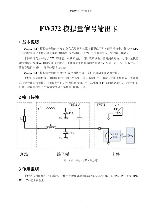
FW372模拟量信号输出卡1基本说明FW372(B)模拟信号输出卡为8路点点隔离型电流(Ⅱ型或Ⅲ型)信号输出卡。
作为带CPU 的高精度智能化卡件,具有实时检测输出状况功能,它允许主控制卡监控正常的输出电流。
卡件设计充分利用了CPU的性能,可独立运行,自行故障诊断,检测到故障后,可进行无扰动在线切换。
当SCnetⅡ网络通信中断时,卡件接受主控制器的数据命令,维持正常工作;当卡件与主控制器通信中断时,可保持原输出状态。
FW372(B)模拟信号输出卡设计有带电插拔电路,支持无扰动在线更换卡件。
卡件的前端面板有一组面板指示灯和一个按钮开关。
指示灯用于指示卡件的工作状态;按钮开关用于卡件的热插拔,在插拔卡件前,先按住此按钮。
卡件后端接有64脚的欧式插针,用于卡件的供电、与数据转发卡的数据交换以及模拟信号的输出等。
2接口特性图 2-1接口特性(以第1路为例)3使用说明卡件结构简图如图 3-1所示。
卡件由底板和背板两部分组成,其中J1、J6、JP1、JP2、JP3、JP4、JP5、JP6位于底板上。
图 3-1 FW372(B)结构简图3.1LED指示灯说明表 3-1指示灯说明3.2跳线表3-2 FW372(B)跳线设置跳1-2 正常工作状态JP1跳2-3 标定状态(用户禁止使用)跳1-2 单卡配置JP6跳2-3 冗余配置跳1-2 (HART通信保留)JP2,JP3跳2-3 (HART通信保留)跳1-2 (HART通信保留)JP4,JP5跳2-3 (HART通信保留)J1 跳7-8 IC1的下载接口,下载时连接下载线。
在正常工作中使用短路块连接7、8脚,其余引脚全部断开。
J6 IC2的下载接口,下载时连接下载线。
正常工作中全部断开跳1-2跳2-3J1跳7-8图 3-2 FW372(B)卡跳线示意图3.3端子板选择FW372(B)模拟信号输出卡在使用时必须与对应的端子板配合使用,端子板提供接线通道以及信号前级抗扰动处理。
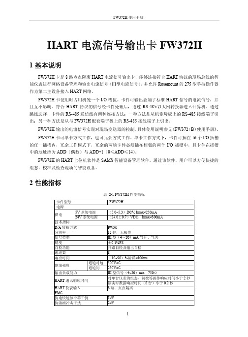
HART电流信号输出卡FW372H1基本说明FW372H卡是8路点点隔离HART电流信号输出卡,能够连接符合HART协议的现场总线的智能仪表进行网络设备管理和输出电流信号(Ⅲ型电流信号),并允许Rosemount的275型手持操作器作为第二主设备接入HART网络。
FW372H卡使用时占用机笼一个I/O槽位。
卡件可输出叠加了标准HART信号的电流信号,并且互不影响。
符合HART协议的信号经卡件处理后,通过RS-485/以太网转换器进入计算机。
通过跳线选择,卡件的RS-485通信线有两种连接方法:一种方法是从机笼母板上的RS-485接线端子引出;另一种方法是从与FW372H配套端子板上的RS-485接线端子上引出。
FW372H输出的电流信号实现对现场变送器的控制。
具体使用说明参见《FW372(B)使用手册》。
FW372H卡可单卡方式工作,也可冗余方式工作。
单卡工作方式下,卡件可插在16个I/O插槽的任一插槽内,冗余工作模式下,冗余的两块卡件必须插在相邻的两个I/O插槽中,且卡件在插槽中的地址应为ADD(偶数)与ADD+1(0≤ADD≤14)。
FW372H的HART上位机软件是SAMS智能设备管理软件。
通过该软件,用户可以方便快捷的组态、校准及检查现场的智能设备。
2性能指标表 2-1 FW372H性能指标卡件型号FW372H电源5V系统电源(5.0~5.3)DCV, Imax<250mA供电24V系统电源(24.0±0.7)VDC,Imax<300mA技术指标D/A转换方式PWM分辨率 12位,无极性信号类型 III型(4~20)mA气开、气关精度±0.1%FS自检功能开路自检及输出自检通道数8响应时间(10~90)%阶跃<100ms通道对地500V AC绝缘强度通道间250V AC输出负载能力 III型信号(4~20)mA 750Ω对单台仪表的组态、调校等操作响应时间小于2秒HART通讯响应时间读实时数据响应时间(8台)小于0.2秒HART仪表输入8路、点点隔离EMC抗电快速脉冲群干扰1kV抗浪涌冲击干扰2kV抗射频电磁波干扰10V/m抗静电放电干扰空气放电8kV,接触放电6kV其它工作温度(0~50)℃工作湿度(10~90)%,无凝露存储和运输温度(-40~+80)℃存储湿度(5~95)%,无凝露工作大气压(62~106)kPA3接口特性图 3-1接口特性图4使用说明卡件结构简图如图 4-1所示。

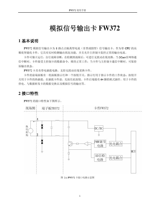
模拟信号输出卡FW3721基本说明FW372模拟信号输出卡为8路点点隔离型电流(Ⅱ型或Ⅲ型)信号输出卡。
作为带CPU的高精度智能化卡件,它具有实时检测输出状况功能,并且允许主控制卡监控正常的输出电流。
卡件可独立运行,自行故障诊断,在检测到故障后,可进行无扰动在线切换。
当SCnetⅡ网络通信中断时,卡件接受主控制卡的数据命令,维持正常工作;当卡件与主控制卡通信中断时,可保持原输出状态。
FW372卡具有带电插拔电路,支持无扰动在线更换卡件。
卡件的前端面板有一组面板指示灯和一个按钮开关。
指示灯用于指示卡件的工作状态;按钮开关用于卡件的热插拔,在插拔卡件前,先按住此按钮。
卡件后端接有64脚的欧式插针,用于卡件的供电、与数据转发卡的数据交换以及模拟信号的输出等。
2接口特性FW372的接口特性如下图所示。
图 2-1 FW372卡接口电路示意图3使用说明卡件外形图如图 3-1所示:图 3-1 FW372卡件外型图3.1LED指示说明表 3-1 FW372指示灯说明3.2跳线表 3-2 FW372跳线说明下图为不同工作方式下的跳线选择。
图 3-2 FW372卡件跳线示意图系统更新功能主要是给卡件微处理器下载内置程序用。
一般卡件出厂时由厂方进行内置程序下载,以后内置程序版本升级时才用到,用户不使用此功能。
JP7只用于设置卡件正常工作和标定的状态。
正常工作:跳1-2;标定:跳2-3。
3.3卡件工作方式FW372卡可单卡工作,也可冗余工作。
单卡工作模式下,卡件可插在16个I/O插槽的任一插槽内;冗余工作模式下,冗余的两块卡件必须插在相邻的两个I/O插槽中,且卡件地址应为ADD(偶数)与ADD+1。
3.4端子板选择FW372模拟信号输出卡在使用时必须与对应的端子板配合使用,端子板的功用为提供接线通道以及信号前级抗扰动处理。
具体情况请参照对应端子板的详细介绍。
选配标准如下。
表 3-3 FW372端子板选配标准描述型号使用范围备注8路电流输出端子板TB372-R 电流信号可配置两冗余FW372卡16路电流输出端子板TB372 电流信号可配置两不冗余FW372卡8路电流输出与HART 通信端子板TB372-HART电流信号和HART通信可连接FW372卡和FW356卡4性能指标表 4-1 FW372性能指标型号FW372电源5V电源(5±0.3)VDC, Imax<100mA供电24V电源(24±0.7)VDC,Imax<10mA(不含扩展设备)(24±0.7)VDC,Imax<170mA(含扩展设备)技术指标通道数8路通道隔离方式点点隔离现场侧与系统侧500V AC,50Hz,60s 隔离电压通道间 250V AC,50Hz,60s(0~10)mA DC输出范围(4~20)mA DC(0~10)mA DC ≤1500Ω负载能力(4~20)mA DC ≤750Ω精度±0.2%FS通信故障自检与报警指示通信中断,数据保持输出通道故障自检与报警指示通道自检错误共模抑制比120dB串模抑制比60dBEMC指标抗电快速脉冲群干扰信号线与地1kV抗浪涌冲击干扰信号线之间0.5kV,信号线与地1kV抗射频电磁波干扰10V/m抗静电放电干扰空气放电8kV,接触放电6kV其它工作温度≥0℃,≤+50℃工作湿度≥5%,≤90%(不结露)存储温度≥-40℃,≤+70℃存储湿度≤95%(不结露)工作大气压≥62 kPa,≤108kPa5工程应用举例FW372卡可以输出II型和III型电流信号,配合现场设备使用。

3/4"Drive Digital TorqueAdapterWhen unpacking your new digital torque adapter and related parts& accessories,please inspect it carefully for any damage that may have occurred during transit.If you have any questions,or require assistance with damaged or missing parts,please contact our factorycustomer service department at:1-800-386-0191Please have the serial number,model number,and date of purchase available for reference when calling.This instruction manual is intended for your benefit.Please read and follow the safety,installation,maintenance and troubleshooting steps described within to ensure your safety and satisfaction.The contents of this instruction manual are based upon the latest product information available at the time of publication.Due to continuing improvements,actual product may differ slightly from the prod-uct described herein.Tools required for assembly and servicing are not included.INTRODUCTIONAfter opening the carton,unpack your new digital torque wrench adapter and related parts &acces-sories.Please inspect it carefully for any damage that may have occurred during transit.Please check it against the photograph on carton.If any parts are missing,please call factory customer ser-vice at 1-800-386-0191.UNPACKING &INSPECTIONDo not operate this tool if damaged during shipment,handling or misuse.Do not operate the tool until the parts have been replaced or the fault rectified.Failure to do so may result in serious per-sonal injury or property damage.All damaged parts must be repaired or replaced asneeded prior to operating this tool.Check to see that all nuts,bolts and fittings are secure before putting this tool into service.If you have any questions,or require assistance with damaged or missing parts,please contact our factory customer service department at:1-800-386-0191Please have the serial number,model number,and date of purchase available for reference whencalling.WARNING -RISK OF FLYING PARTICLESREAD THIS MANUAL COMPLETELY BEFORE USING THE DIGITAL TORQUE ADAPTER•To insure accuracy,work must not move in angle mode.•For personal safety and to avoid adapter damage,follow good professional tool and fas-tener installation practices.•Periodic recalibration is necessary to maintain tool accuracy.USERS AND BYSTANDERS SHOULD ALWAYS WEAREYE PROTECTION•Besure all components,including adapters,extensions,drivers and sockets are rated to match or exceed the torque being applied with tool.•Observe all equipment,system and manufacturer’s warnings,cautions and procedures when using this adapter.•Always use the correct size socket for the fastener being torqued.•Do not use damaged sockets,showing signs of wear or cracks.•Always replace damaged fasteners before applying torque.WARNING -Electrical Shock Hazard•Electrical shock can cause injury.•Plastic handle is not insulated.•Do not use on live electrical circuits.Over-torquing can cause breakage.An out of calibration torque wrench can cause part or tool breakage.Broken hand tools,sockets or accessories can cause injury.Excess force can cause crow foot or flare nut wrench slippage.IMPORTANT SAFEGUARDSIMPORTANT SAFEGUARDSto applying torque.•Never use this digital torque adapter to loosen fasteners as damage may occur.•Do not exceed the rated maximum torque value for the digital torque adapter as break-age and/or a loss of accuracy could occur.•Always verify the calibration of the digital torque adapter if you know or suspect its capac-ity has been exceeded.•Always pull-do not push-on the drive tool(ratchet)handle that is connected to the digi-tal torque adapter.•Adjust your stance to prevent a possible fall while applying torque.•Apply torque slowly and grasp the center of the handle.Do not apply load to the end ofthe handle.•Avoid applying excessive torque,turn the ratchet slowly and steadily as you apply torque.Pay attention to the LED light and sound indicators.•Never submerge the digital torque adapter in water or any other liquid.•If the tool gets wet,immediately wipe it dry with a soft,clean towel.•Do not expose this wrench to dust or sand as this could cause serious damage.•Use the digital torque adapter only for its intended purpose as described in this manual.•Do not use the digital torque adapter if it is not working properly or if it has suffered anydamage.•Do not disassemble the digital torque adapter.•Do not expose the digital torque adapter to extreme temperatures,humidity,direct sun-light.•Do not shake violently or drop digital torque adapter.•Do not use this tool as a hammer.•Position batteries in proper polarity.•Do not mix batteries of different type.•Never clean the digital torque adapter with soap or solvents.•Use a soft,dry,clean cloth to clean the digital torque adapter and LCD panel.•Do not apply excessive force to the LCD display panel.•Store in a clean dry place.•Keep this tool away from magnets.PRODUCT SPECIFICATIONSDrive size:3/4inchAccuracy:CW:±1%CCW:±2%Memory presets:10Display resolution:0.1NmOperation mode:Peak/TraceUnit selection:kg-cm,kg-m,lb-in,lb-ft,N-mBattery:AAA x2pcsAmbient temperature range:Operating:-10°C–60°C(13.9°F–139.9°F)Storage:-20°C-70°C(-4°F–157.9°F)Auto shut-off:80secondsTorque range:50-600Ft-lbs(67.8-813.5N-m)PRODUCT FEATURES•Digital torque readout.•Selectable for five torque units of measure:lb-ft,lb-in,kg-cm,kg-m and N-m.•+/-1%CW and +/-2%accuracy•Clockwise (CC)and counterclockwise (CCW)operation indicated on display.•Peak torque hold mode and Tracking torque mode selectable.•White LED backlight for easy reading.•Reverisble LCD display viewing orientation.•Multiple preset torque value indicators:audible buzzer,vibration alarm,red LED warning light.•Displays percentage of preset torque value attained.•Power saving automatic sleep mode activates after 3minues of inactivity.•Uses two (2)AAA size batteries.•Batteries,storage caseand calibration adapterincluded.LCD displaywithbacklight Extension bar ModeKEYBOARDUnitsPeak hold/TraceDigit shiftAdd valueMode The Titan Digital Torque Adapter displays fastener torque specification settings,torque readings and peak hold measurements.Buzzerpreset torque battery icon value of measure LCD DISPLAY INDICATORSWhen battery voltage drops below 2.6volts,a low battery warning icon willappear on the LCD display.When the battery voltage drops below 2.4volts,the low battery warning icon will begin to flash,indicating that immediate battery replacement isrequired.LOW BATTERY VOLTAGE INDICATIONBattery voltage under 2.4VPOWERING ON DIGITAL TORQUE ADAPTERPress Mode button to turn digital torque adapter on and activate auto-zeroing process.Auto-zeroing processNormal mode(Preset number 0shown)CAUTION:Make sure the displayed applied torque value is zero during the auto-zeroing period.Otherwise a torque offset will be included.Select 1of 10user programable memory presets.SELECTING MEMORY PRESETSSETTING PRESET VALUES4.Five different unit selections are available:kg-cm,k-gm,in-lb,ft-lb,and N-m.SELECTING UNITS OF MEASURENOTE:When you change units,any target torque setting you have already entered will now be displayed in the new unit value.SELECTING PEAK HOLD/TRACKING MODESPressIn Track mode -The display will register “real-time”torque as it is applied.This is useful when you are able to observe the digital display while applying torque to a fastener.Watching the torque value increase can assist you in applying torque evenly and safely,especially as you approach your target torque setting.FullyreleaseDisplay retains peak torque achieved.PEAK HOLD MODE OPERATIONPeak Hold ModePercent of Target torqueApplytorque activatesRelease torque to zero-out torquereading and then apply torque again.Select pre-setting:200kg-cm(in this example)Applytorque and hold2sec.Toggle screen from Auto mode to Manual mode.Continue applying torque until preset torque value In Peak hold mode,the digital display shows the maximum torque applied,which can be helpful for verifying that the correct torque was applied when the digital display is not visible during use.This mode is also handy when using the adapter to calibrate a torque wrench.TRACKING MODE OPERATIONTracking ModeAt50%of Target torque:•Percentage of preset torque value is displayed•Buzzer sounds:Bi---Bi---Bi---•Select pre-setting:200kg-cmApply torque to reach preset torque value(200kg-cm in this example)At70%of target torque:At90%of target torque:At100%of target torque:•Percentage of preset torque value is displayed•Buzzer sounds:Bi-Bi-Bi-Bi•Red LED flashes:alert•Percentage of preset torque value is displayed•Buzzer sounds:BiBiBiBiBiBiBi•Percentage of preset torque value is displayedApplytorqueApplytorqueApplytorqueIn Tracking mode,the display will register torque as it is applied in real-time.This allows you to observe the digital display while applying torque to a fastener.Watching the torque value increase can assist you in applying torque evenly and safely,especially as you approach your target torque setting.1.Requires two (2)alkaline AAA batteries.2.Unscrew battery cover fastener with 2.5mm hex key wrench.3.Remove the battery cover.4.Remove the old batteries.5.Clean battery terminals.6.Install fresh batteries in the digital torque adapter (with the “+”sign ends away from the contact springs).7.Replace the battery cover and screw tight.Note•Remove batteries if stored for a long period of time.•DO NOT mix batteries by type,brand,or condition.•Oil,water,dirt and sweat can prevent a battery’s terminals from making electrical contact.Wipe both terminals before installing batteries.•Typical battery life is 2000uses.Battery disposalOnly dispose of batteries when they are fully discharged.DO NOT dispose of batteries in a fire.Dispose of expended batteries and packaging materials in an environmentally responsible manner.Press and hold Mode button for 2seconds to turn unit off.NOTE:This tool will automatically enter sleep mode after 3minutes of inactivity.BATTERYINSTALLATIONANDREPLACEMENT POWERING OFF DIGITAL TORQUEADAPTORPress and for 2seconds to toggle the orientation of the display readout.CHANGING ORIENTATION OFDISPLAYPressCALIBRATING A TORQUE WRENCH USING DIGITAL ADAPTER 1.Set your torque wrench to a value of approximately25%of its maximum capacity.For example,ifyour torque wrench has a maximum capacity of150lb-ft,set it to40lb-ft.2.Program the digital torque adapter for a torque value that matches the torque wrench setting.Inour example,you would set the adapter for40lb-ft.Ensure the adapter is in the“peak”mode as this will make it easy to reference actual torque versus the torque indicated on the wrench.3.Connect the pre-set torque wrench and the included calibration adapter to the digital torque adapt-er.Secure the calibration adapter in a bench vise.Ensure the calibration adapter is securely tight-ened in the vise.4.Turn the torque wrench smoothly and steadily,applying torque to the calibration adapter until yourtorque wrench reaches the preset value,either by“clicking”(micrometer style torque wrench),or displaying the desired setting(digital or dial torque wrench).5.Read the peak torque value shown on the digital torque adapter.Adjust your torque wrench andrepeat the procedure until the trque wrench and digital torque adapter show identical torque val-ues.PLEASE NOTEDisposalDo not dispose of this device in normal domestic waste.Observe the currently valid regulations.In case of doubt,consult your waste disposal facility.IMPORTANT-Service,repair and calibration are to be performed by Star-Asia USA,LLC only.Cali-bration by the user is recorded in the wrench and voids factory certification.Contact Star-Asia USA, LLC for information on calibration service.USER QUICK REFERENCE GUIDEMeasure Torque Presetting Target Torque90DAY LIMITED WARRANTY-STAR ASIA-USA,LLC POWER TOOLSStar Asia-USA,LLC(hereinafter“seller”)warrants to the original purchaser only,that this product will be free from defects in material or workmanship for a period of one year from date of purchase for home domestic use. Warranty PerformanceWarranty coverage is conditioned upon purchaser furnishing seller or its authorized service center with adequate written proof of the original purchase date.Products returned,freight prepaid and insured,to our factory or to an Authorized Service Center will be inspected and repaired or replaced,at seller‘s option,free of charge if found to be defective and subject to warranty.Defective parts not subject to normal wear and tear will be repaired or replaced,at our option during the above stated warranty periods.In any event,reimbursement is limited to the pur-chase price paid.Other than the postage and insurance requirement,no charge will be made for repairs or replacements covered by this warranty.Under no circumstances shall the manufacturer bear any responsibility for loss of the unit,loss of time or rental,inconvenience,commercial loss or consequential damages.There are no warranties which extend beyond the description of the face hereof.ExclusionsThis warranty does not cover parts damaged due to normal wear,abnormal conditions,misapplication,misuse, abuse,accidents,operation at other than recommended pressures or temperatures,improper storage or freight damage.Parts damaged or worn by operation in dusty environments are not warranted.Failure to follow recom-mended operating and maintenance procedures also voids warranty.Additional items not covered under this warranty:product failure caused by rain,excessive humidity,corrosive environments or other contaminants;cosmetic defects that do not interfere with product‘s functionality.This warranty shall not apply when:the product has been used for commercial or rental purposes;defects in mate-rials or workmanship or damages result from repairs or alterations which have been made or attempted by others or the unauthorized use of nonconforming parts;this damage is due to abuse,improper maintenance,neglect or accident;or the damage is due to use of the product after partial failure or use with improper accessories.Warran-ty does not apply to accessory items such as batteries.Seller will not be liable for:labor charges,loss or damage resulting from improper operation,maintenance or repairs made by persons other than a Star Asia-USA,LLC Authorized Service Center.The use of other than genuine Star Asia-USA,LLC Repair Parts will void warranty.Warranty DisclaimersNO WARRANTY,ORAL OR WRITTEN,OTHER THAN THE ABOVE WARRANTY IS MADE WITH REGARD TO THIS PRODUCT,ANY IMPLIED WARRANTIES OF SELLER REGARDING THIS PRODUCT INCLUDING BUT NOT LIMITED TO,THE IMPLIED WARRANTIES OF MERCHANTABILITY OR FITNESS FOR A PARTICULAR PURPOSE,ARE EXCLUDED.BUYER‘S OR USER‘S REMEDIES ARE SOLELY AND EXCLUSIVELY AS STATED ABOVE.STAR ASIA-USA,LLC SHALL IN NO EVENT BE LIABLE FOR INCIDENTAL,CONSEQUENTIAL,INDI-RECT,OR SPECIAL DAMAGES.IN NO EVENT,WHETHER AS A RESULT OF A BREACH OF CONTRACT, WARRANTY,TORT(INCLUDING NEGLIGENCE)OR OTHERWISE,SHALL SELLER‘S LIABILITY EXCEED THE PRICE OF THE PRODUCT WHICH HAS GIVEN RISE TO THE CLAIM OR LIABILITY.ANY LIABILITY CON-NECTED WITH THE USE OF THIS PRODUCT SHALL TERMINATE UPON THE EXPIRATION OF THE WAR-RANTY PERIODS SPECIFIED ABOVE.Limitations on Warranty DisclaimersAny implied warranties shall be limited in duration to one year from the date of purchase.In some states of the U.S.A.and in some provinces of Canada there is no limitation for how long an implied warranty is valid,so the aforementioned limitation may not apply to you.Star Asia-USA,LLC(hereinafter“seller”)warrants to the original purchaser only,that this product will be free from defects in material or workmanship for a period of one year from date of purchase for home domestic use. Distributed by Star Asia-USA,LLCP.O.Box58399,Renton,WA98058Consumer Service:800-386-0191e-mail:*****************©2013Star Asia-USA,LLC。
OverviewTM SIWAREX WP341 HF weighing electronicsTM SIWAREX WP341 HF weighing electronicsThe SIWAREX WP341 is a compact, precise weighing electronics in the SIMATIC ET 200SP format.With a width of just 20 mm it is one of the slimmest weighing electronics on the market, yet its firmware includes the functionalities of a continuous belt weighing electronics. Optionally the WP341can be used for operation of solids flowmeters.The load cells and the speed sensor are directly connected to the ET 200SP Base Unit (type U0) and therefore the complete system is directly integrated into the automation system.•Low space requirements with only 20 mm module width •Seamless integration into SIMATIC ET 200SP •1 000 Hz sampling rate und processing time•Dedicated firmware for continuous belt weighing applications •Operation with SIMATIC S7-300, S7-400, S7-1200 and S7-1500controllers•Operation in Ethernet IP or Modbus TCP-based systems using ET 200SP multi-field bus IM•Three digital inputs and outputs each ex works•High degree of scalability in connection with all available SIMATIC standard components•Open SIWAREX concept – all settings and parameters accessible,no encapsulated black box in the field•Unrestricted access to all scale parameters and functions from the SIMATIC S7 Controller / HMI•Internal, protocol memory for up to 1 000 000 entries•Commissioning and maintenance from HMI or weighing electronics-internal web server•Advanced diagnostic features in combination with SIWAREX DBSIWAREX WP341 offers a compact and extremely versatile solution for continuous belt weighing applications with high requirements for accuracy and performance.Typical areas of application include:•Belt weighers in recycling, mining, aggregate, cement, chemical and food industries•Easy and completely integrated realization of weigh feeding applications•Operation with solids flowmetersThe SIWAREX WP341 is a technology module of the SIMATIC ET 200SP distributed I/O system.Installation is on a type U0 BaseUnit. The load cells, serial RS 485interface and digital inputs/outputs are wired directly on theBaseUnit with user-friendly push-in terminals. This makes is quick and easy to replace weighing electronics without any wiring effort. The web server is addressed via an Ethernet interface in the weighing electronics. Should more interfaces and I/O be required, they can be added with the ET 200SP system components.The load cells of the belt scale as well as the speed sensor are directly wired to the BaseUnit. The weighing electronics internally calculates the current flow rate based on the current weight and speed signal. Six individual totalizers are available and can be easily read out of the weighing electronics into the connected CPU. The totalizers are resettable by software command or alternatively by a 24 V signal connected to one of the on board digital inputs. Different methods of commissiong are supported: by test weight, by test chain, by material batch or based on load cell data.A correction factor calculated by a material test can be applied.Additionally a correction factor curve based on different belt load levels can be defined. Digital signal filters for speed and load offer the possibility to optimize the results of the weighing process. A logging function for all calibration actions with time stamp provide a transparent and secure operation of the scale. In combination with the digital junction box SIWAREX DB up to four connected load cells can be individually monitored and diagnosed down from the single sensor up into the MES level.The free of charge function block and HMI visualization give full access to all available data and parameters of the WP341 from the controller / HMI. Therefore the belt weighing application can be easily integrated into existing HMI visualizations and allow an intuitive operation and service of the scale.© Siemens AG 2023TM SIWAREX WP341 HF weighing electronicsTM SIWAREX WP341 HF weighing electronicsTM SIWAREX WP341 HF weighing electronics。
SPECIFICATIONSService: Compatible liquids and gases, adhesives, slurries, materials that canharden, or where a pressure cavity is not desired.Wetted Materials:316 & 15-5 SST.Accuracy: ±0.5% FSO (includes non-linearity, hysteresis, and repeatability).Stability: ≤ ±0.25% FSO per year.Temperature Limits: -40 to 200°F (-40 to 93°C).Compensated Temperature Limits:0 to 170°F (-18 to 77°C).Pressure Limit:150% FS; Burst: 200% FS.Thermal Effect:±1.5% FSO over compensated range.Power Requirements: 8 to 38 VDC.Output Signal:FDT-A: 4 to 20 mAdc; FDTV: 0 to 5 VDC.Response Time: <1mS.Loop Resistance:FDT-A: 0-1.5 Ω; FDT-V: ≤ 100 Ω.Electrical Connections: Bendix 4 pin.Process Connection:7/16-20 UNF Male Flush Diaphragm. Optional 1/4” maleNPT.Enclosure Rating:NEMA 4x (IP66).Mounting Orientation:Mount in any position.Weight: 2 oz (57 g).Agency Approvals:CE.The Series FDT Flush Diaphragm Transmitter is designed for highly cyclicalconditions. This unit has a non-oil filled sensor element that provides resistance totemperature fluctuations. Manufactured from a solid piece of steel, the sensingdiaphragm can withstand the most abrasive/cyclical applications. Unit performswell in high cyclical environments with the presence of water-hammering orspiking.Flush feature greatly reduces chance of leakage. Tough materials allow the unit towithstand harsh process conditions. Advanced manufacturing techniques, extremeenvironmental burn-in, and thorough residual stress relieving procedures ensureunit will maintain its high performance standard over time.INSTALLATIONLocationSelect a location where the temperature of the transmitter will be between -40 and200°F (-40 to 93°C). Distance from the receiver is limited only by total loopresistance. The tubing or piping supplying pressure to the unit can be practicallyany length required but long lengths will increase response time slightly.PositionThe transmitter is not position sensitive. However all standard models are originallycalibrated with the unit in a position with the pressure connection downward.Although they can be used at other angles, for best accuracy it is recommendedthat units be installed in the position calibrated at the factory.Pressure ConnectionUse a small amount of plumbers tape‚ thread tape or other suitable sealants toprevent leaks. Be sure the pressure passage inside the port is not blocked.Electrical ConnectionsUnits must “see” the proper excitation to perform within specifications. Insufficientpower may prevent the unit from providing the full rated output at the full ratedpressure. Electronics can be damaged by electric surges. Surge arresters aresuggested for applications where surges are possible. Mechanical isolation mayalso be required. Electrical termination must be made in a NEMA 4 enclosure.Care must be taken to prevent migration of fluid into the cable jacket. Unlessotherwise specified, the unit’s electronics should not be exposed to temperaturesabove 250°F.Note:Wrench only on the wrench flats for mounting or removing the unit. Do notuse the housing or electrical termination for wrenching. The pressure cavities ofFDT series unless otherwise specified are manufactured with 15-5 and 316stainless steels and are suitable for use with all media compatible with thosematerials. Foreign objects should not be introduced into the pressure cavity. Unitsmust be protected from exposure to transient pressure spikes and pressures overtheir rated proof pressure range.CURRENT (4 to 20 mA) OUTPUT OPERATIONAn external power supply delivering 8 to 38 VDC with minimum current capabilityof 40 mA DC (per transmitter) is required to power the control loop. See Fig. A forconnection of the power supply, transmitter and receiver. The range of appropriatereceiver load resistance (RL) for the DC power supply voltage available isexpressed by the formula:RL Max = Vps - 820 mA DCShielded cable is recommended for control loop wiring.VOLTAGE (0 to 5 V) OUTPUT OPERATION(Other output contact the factory) See Fig. A for connection of the power supply,transmitter and receiver.MAINTENANCEAfter final installation of the pressure transmitter and its companion receiver, noroutine maintenance is required. A periodic check of system calibration issuggested. The Series FDT transmitters are not field reparable and should bereturned if repair is needed (field repair should not be attempted and may voidwarranty). Be sure to include a brief description of the problem plus any relevantapplication notes. Contact customer service to receive a return goods authorizationnumber before shipping.0 - 5 or 0 - 10 VDC MODELStandard WiringMODELFDT-VFDT-AOUTPUT0-5 VDC 3 Wire4-20 mAdcPower(+)Pin APin APower(-)Pin BSignal(+)Pin CPin BFig. ADo not exceed specified supply voltage ratings. Permanentdamage not covered by warranty will result. This device is notdesigned for 120 or 240 volt AC operation. Use only on 8 to 38 VDC.。
Description High Voltage Current Mode Step-Down ConverterDemonstration Circuit 736A is a 200kHz high voltage, current-mode DC/DC step-down converter featuring the L T®3724.The circuit operates from a V IN range of 30V to 55V and outputs 24V at 3A (72W). A soft-start feature controls the output voltage slew rate at start-up, reducing current surges and voltage overshoots. Burst Mode® operation that improves the efficiency at light loads can be enabled with a jumper.An optional boost bias circuit is provided on the bottom side of the board for back-driving the LT3724 internal regulator from the output voltage. Customers might want to use this optional circuit with modified applications that have relatively high input voltages and low (~5V) output voltages. In such applications, the optional circuit can increase the overall efficiency by reducing the power lostperformance summary in the LT3724. The demonstration circuit has also been layed out with the option for a second switching MOSFET to facilitate higher output currents. The circuit design can be modified for a boost converter configuration.This circuit is suitable for a wide range of Industrial control systems and particularly suitable for 12V/42V automotive applications and 48V Telecom power supplies.The LT3724 data sheet gives a complete description of the part, operation and application information. The data sheet must be read in conjunction with this demo manual. Design files for this circuit board are available at /demoL, L T, L TC, L TM, Linear Technology, the Linear logo and Burst Mode are registered trademarks of Linear Technology Corporation. All other trademarks are the property of their respective owners.Specifications are at T A = 25°CPARAMETER CONDITIONS MIN TYP MAX UNITS Input Voltage Range3055VEfficiency V IN = 30V, I OUT = 3.0AV IN = 48V, I OUT = 3.0AV IN = 55V, I OUT = 3.0A 97.495.494.7%%%Switching Frequency200kHz Output Voltage I OUT = 0A to 3.0A24V Output Voltage Ripple V IN = 48V, I OUT = 3.0A 100mV1dc736af2dc736afQuick start proceDureDC736A is easy to set up to evaluate the performance of the LT3724. Refer to Figure 1 for proper measurement equipment setup and follow the procedure below:NOTE: When measuring the input or output voltage ripple, care must be taken to avoid a long ground lead on the oscil-loscope probe. See Figure 2 for the proper scope technique. 1. Place JP1 in the RUN position.2. Place JP2 in the desired operating mode: fixed frequency or Burst Mode operation.3. With power off, connect the input power supply to V IN and GND.4. With power off, connect the load to V OUT and GND.5. Turn on the power at the input and adjust the input voltage until the LT3724 turns on. NOTE: Make sure that the input voltage does not exceed 55V.6. Check for the proper output voltage.NOTE: If there is no output, temporarily disconnect the load to make sure that the load is not set too high or is shorted.7. Once the proper output voltage is established, adjust the input voltage and load within the operating range and observe the output voltage regulation, ripple voltage,efficiency and other parameters.Figure 1. Proper Measurement Equipment SetupFigure 2. Measuring Output Rippleparts ListITEM QTY REFERENCE PART DESCRIPTION MANUFACTURER/PART NUMBER11CIN1Cap., Aluminum 68µF 63V 20%Sanyo 63MV68AX-T22CIN2, CIN3 Cap., X7R 2.2µF 100V 20%TDK C4532X7R2A225M31COUT1 Cap., Alum 330µF 35V 10%Sanyo 35CV330AX-T42COUT3, COUT2 Cap., X7R 22µF 25V 20%TDK C5750X7R1E226M51C1 Cap., NPO 1000pF 100V 10%AVX 08051A102KAT1A61C2 Cap., X5R 0.22µF 16V 10%Taiyo Yuden EMK107BJ224KA71C3 Cap., X7R 1000pF 25V 10%AVX 04023C102KAT2A81C4 Cap., X5R 0.1µF 16V 10%AVX 0402YD104KAT2A91C5 Cap., X5R 1µF 16V 10%Taiyo Yuden EMK212BJ105KG101C6 Cap., X7R 120pF 25V 10%AVX 04023C121KAT2A111C7 Cap., X7R 1500pF 16V 20% 0402AVX 0402YC152MAT2A121C12Cap., X7R 0.01µF 16V 10%AVX 0402YC103KAT2A131D1 Diode, Speed Switching Diodes Inc. BAS19141D2 Schottky Diode 60V IR 30BQ060151D5Diode, 75V/200mW Diodes Inc. 1N4148WS161L1 Inductor, 47µH Coilcraft DO5040H-473MLB171Q1 MOSFET N-Channel, PowerPak SO8 Vishay Siliconix Si7852DP181R1 Res, Chip 1M 0.1W 5%AAC CR10-105JM191R2 Res/Jumper, Chip 0Ω 0.06W 1A AAC CJ05-000M201R3 Res., Chip 52.3k 1/16W 1%Vishay CRCW0402 52.3K 1%211R4 Res., Chip 402K 1/16W 1%AAC CR05-4023FM221R5 Res., 0.025 0.5W 1%IRC LRF2010-01-R025-F231R6 Res., Chip 1M 0.1W 5%AAC CR16-105JM241R7 Res., Chip 4.99k 0.06W 1%AAC CR05-4991FM251R8 Res., Chip 93.1k 1/16W 1%AAC CR05-9312FM261R9 Res., Chip 2.21k 1/16W 1%AAC CR05-2211FM271R14Res., Chip 470 1/16W 5%AAC CR05-471JM281R15Res., Chip 47k 1/16W 5%AAC CR05-473JM291U1 I.C., Voltage Regulator Linear Technology Corporation LT3724EFE Additional Demo Board Circuit Components10C8 Cap., X5R C-4.7µF, 6.3V-0805 6.3V 20%Taiyo Yuden JMK212BJ475MG-T20C9 Cap., X5R 1µF 16V 20%Taiyo Yuden EMK212BJ105MG30C10 Cap., NPO 220pF 25V 10%AVX 04023A221KAT2A40C11Cap., Aluminum 22µF 35V 10%Sanyo 35MV22UAX50D3,D4 Schottky Diode, 40V Zetex ZHCS40060L2 Inductor, L-10µH Murata LQH3C100M2470R10 Res./Jumper, Chip 0Ω 0.06W 1A AAC CJ05- 000M80R11 Res., Chip 107k 0.06W 1%AAC CR05-1073FM90R12 Res., Chip 10k 0.06W 5%AAC CR05-103JM100R13 Res., Chip 12.4k 1/16W 1%AAC CR05-1242FM110U2 I.C., Voltage Regulator Linear Technology Corporation LT1613CS53dc736afparts ListITEM QTY REFERENCE PART DESCRIPTION MANUFACTURER/PART NUMBER Hardware – For Demo Board Only14E1, E2, E3, E4 Testpoint, Turret Mill Max 2501-220E5 Testpoint, Turret Mill Max 2501-232JP2, JP1 Headers, 3 Pins 2mm Ctrs. Comm Con Connectors 2802S-03G242XJP1, XJP2JMP, 3 Pin 1 Row .079CC Comm Con Connectors CCIJ2MM-138GW 4dc736af5dc736afInformation furnished by Linear Technology Corporation is believed to be accurate and reliable. However, no responsibility is assumed for its use. Linear Technology Corporation makes no representa-tion that the interconnection of its circuits as described herein will not infringe on existing patent rights.schematic Diagram6dc736afLinear Technology Corporation1630 McCarthy Blvd., Milpitas, CA 95035-7417(408) 432-1900 ● FAX : (408) 434-0507 ● www.linear .comLINEAR TECHNOLOGY CORPORA TION 2012LT 0912 • PRINTED IN USADEMONSTRATION BOARD IMPORTANT NOTICELinear Technology Corporation (L TC) provides the enclosed product(s) under the following AS IS conditions:This demonstration board (DEMO BOARD) kit being sold or provided by Linear Technology is intended for use for ENGINEERING DEVELOPMENT OR EVALUATION PURPOSES ONL Y and is not provided by L TC for commercial use. As such, the DEMO BOARD herein may not be complete in terms of required design-, marketing-, and/or manufacturing-related protective considerations, including but not limited to product safety measures typically found in finished commercial goods. As a prototype, this product does not fall within the scope of the European Union directive on electromagnetic compatibility and therefore may or may not meet the technical requirements of the directive, or other regulations.If this evaluation kit does not meet the specifications recited in the DEMO BOARD manual the kit may be returned within 30 days from the date of delivery for a full refund. THE FOREGOING WARRANTY IS THE EXCLUSIVE WARRANTY MADE BY THE SELLER TO BUYER AND IS IN LIEU OF ALL OTHER WARRANTIES, EXPRESSED, IMPLIED, OR STATUTORY, INCLUDING ANY WARRANTY OF MERCHANTABILITY OR FITNESS FOR ANY PARTICULAR PURPOSE. EXCEPT TO THE EXTENT OF THIS INDEMNITY, NEITHER PARTY SHALL BE LIABLE TO THE OTHER FOR ANY INDIRECT , SPECIAL, INCIDENTAL, OR CONSEQUENTIAL DAMAGES.The user assumes all responsibility and liability for proper and safe handling of the goods. Further , the user releases L TC from all claims arising from the handling or use of the goods. Due to the open construction of the product, it is the user’s responsibility to take any and all appropriate precautions with regard to electrostatic discharge. Also be aware that the products herein may not be regulatory compliant or agency certified (FCC, UL, CE, etc.).No License is granted under any patent right or other intellectual property whatsoever. L TC assumes no liability for applications assistance, customer product design, software performance, or infringement of patents or any other intellectual property rights of any kind.L TC currently services a variety of customers for products around the world, and therefore this transaction is not exclusive .Please read the DEMO BOARD manual prior to handling the product . Persons handling this product must have electronics training and observe good laboratory practice standards. Common sense is encouraged .This notice contains important safety information about temperatures and voltages. For further safety concerns, please contact a L TC applica-tion engineer .Mailing Address:Linear Technology 1630 McCarthy pitas, CA 95035Copyright © 2004, Linear Technology Corporation。
模拟信号输出卡FW372
1基本说明
FW372模拟信号输出卡为8路点点隔离型电流(Ⅱ型或Ⅲ型)信号输出卡。
作为带CPU的高精度智能化卡件,它具有实时检测输出状况功能,并且允许主控制卡监控正常的输出电流。
卡件可独立运行,自行故障诊断,在检测到故障后,可进行无扰动在线切换。
当SCnetⅡ网络通信中断时,卡件接受主控制卡的数据命令,维持正常工作;当卡件与主控制卡通信中断时,可保持原输出状态。
FW372卡具有带电插拔电路,支持无扰动在线更换卡件。
卡件的前端面板有一组面板指示灯和一个按钮开关。
指示灯用于指示卡件的工作状态;按钮开关用于卡件的热插拔,在插拔卡件前,先按住此按钮。
卡件后端接有64脚的欧式插针,用于卡件的供电、与数据转发卡的数据交换以及模拟信号的输出等。
2接口特性
FW372的接口特性如下图所示。
图 2-1 FW372卡接口电路示意图
3使用说明
卡件外形图如图 3-1所示:
图 3-1 FW372卡件外型图3.1LED指示说明
表 3-1 FW372指示灯说明
3.2跳线
表 3-2 FW372跳线说明
下图为不同工作方式下的跳线选择。
图 3-2 FW372卡件跳线示意图
系统更新功能主要是给卡件微处理器下载内置程序用。
一般卡件出厂时由厂方进行内置程序下载,以后内置程序版本升级时才用到,用户不使用此功能。
JP7只用于设置卡件正常工作和标定的状态。
正常工作:跳1-2;标定:跳2-3。
3.3卡件工作方式
FW372卡可单卡工作,也可冗余工作。
单卡工作模式下,卡件可插在16个I/O插槽的任一插槽内;冗余工作模式下,冗余的两块卡件必须插在相邻的两个I/O插槽中,且卡件地址应为ADD(偶数)与ADD+1。
3.4端子板选择
FW372模拟信号输出卡在使用时必须与对应的端子板配合使用,端子板的功用为提供接线通道以及信号前级抗扰动处理。
具体情况请参照对应端子板的详细介绍。
选配标准如下。
表 3-3 FW372端子板选配标准
描述型号使用范围备注
8路电流输出端子板TB372-R 电流信号可配置两冗余FW372卡
16路电流输出端子板TB372 电流信号可配置两不冗余FW372
卡
8路电流输出与HART 通信端子板TB372-HART
电流信号和
HART通信
可连接FW372卡和
FW356卡
4性能指标
表 4-1 FW372性能指标
型号FW372
电源
5V电源(5±0.3)VDC, Imax<100mA
供电
24V电源(24±0.7)VDC,Imax<10mA(不含扩展设备)(24±0.7)VDC,Imax<170mA(含扩展设备)技术指标
通道数8路通道隔离方式点点隔离
现场侧与系统侧500V AC,50Hz,60s 隔离电压
通道间 250V AC,50Hz,60s 输出范围(0~10)mA DC
(4~20)mA DC
(0~10)mA DC ≤1500Ω
负载能力
(4~20)mA DC ≤750Ω
精度±0.2%FS
通信故障自检与报警指示通信中断,数据保持
输出通道故障自检与报警指示通道自检错误
共模抑制比120dB
串模抑制比60dB
EMC指标
抗电快速脉冲群干扰信号线与地1kV
抗浪涌冲击干扰信号线之间0.5kV,信号线与地1kV
抗射频电磁波干扰10V/m
抗静电放电干扰空气放电8kV,接触放电6kV
其它
工作温度≥0℃,≤+50℃
工作湿度≥5%,≤90%(不结露)
存储温度≥-40℃,≤+70℃
存储湿度≤95%(不结露)
工作大气压≥62 kPa,≤108kPa
5工程应用举例
FW372卡可以输出II型和III型电流信号,配合现场设备使用。
在工程应用中,对应不同的现场实际信号类型,可在组态中设置II型或III型、正输出或反输出。
例如:现场设备为III型气开阀门,卡件采用冗余工作方式。
在工程应用中就应选用一块型号为TB372-R的端子板与此卡件相匹配,I/O卡件组态时选中冗余工作方式,I/O点参数组态时选择信号类型为“III型”和输出特性为“正输出”。
此外卡件跳线设置为:JP2~JP5跳2-3脚,JP6跳1-2脚,JP7跳1-2脚。
6故障分析及维护方法
表 6-1 常见故障及维护方法
序号故障特征故障原因排除方法
1 COM灯暗和数据转发卡无通信检查数据转发卡
2 FAIL灯快闪卡件复位,CPU没有正常工作重新插拔卡件,如仍不正常请更换卡件
3 FAIL灯常亮单卡时某通道故障或卡件公共
电路故障或冗余时卡件公共电
路故障
检查该通道的现场连线,当确定现场该
通道负载无问题时,插拔卡件,如果
FAIL灯继续常亮,则请更换卡件
7资料版本说明
表 7-1版本升级更改一览表
资料版本号输出时间更改说明FW372使用手册(V1.0)
FW372使用手册(V2.0)2008-11-11
适用硬件模板版本:FW372-V34.43.00 更改故障分析及维护方法FAIL灯常亮项。