单串口ETH001快速使用手册2013
- 格式:docx
- 大小:1.06 MB
- 文档页数:19

Contents1 Introduction (3)2 Hardware Description (3)2.1 Front Panel (3)2.2 LED Indicators (3)2.3 Rear Panel (4)2.4 Specification (4)3 Getting Started (5)3.1 Management Options (5)3.2 Using Web-based Management (5)4.Configuration (6)4.1 Welcome (6)4.2 Administrator (7)4.3 Port Management (11)4.4 VLAN Setting (13)4.5 Per Port Counter (15)Per Port Counter -> Port Counter (15)4.6 QoS Setting (16)4.7 Security (17)4.8 Spanning Tree (19)4.9 DHCP Relay Agent (20)4.10 Backup/Recovery (22)4.11 Miscellaneous (22)4.12 SNMP Settings (23)4.13 Logout (23)4.14 PoE Settings (24)1 IntroductionPower-over-Ethernet (PoE) eliminates the need to run DC power to other devices on a wired LAN. Using a Power-over-Ethernet system, installers need to run only a single Category 5 Ethernet cable that carries both power and data to each device. This allows greater flexibility in the locating of network devices and, in many cases, significantly decreases installation costs.There are two system components in PoE - the PSE (Power Sourcing Equipment) and the PD (Powered Device). The IEEE 802.3af/at specification defines PSE as a device that inserts power onto an Ethernet cable. The PSE may be located at the switch (End-span configuration). or it may be a separate device located between the switch and the PD (Mid-span configuration). The PD is the natural termination of this link, receiving the power, and could be an IP phone, a WLAN access point, or any other IP device that requires power. The current is transmitted over two of the four twisted pairs of wires in a Category-5 cable.Power-over-Ethernet follows the IEEE 802.3af/at specification and is completely compatible with existing Ethernet switches and networked devices. Because the Power Sourcing Equipment (PSE) tests whether a networked device is PoE-capable, power is never transmitted unless a Powered Device is at the other end of the cable. It also continues to monitor the channel. If the Powered Device does not draw a minimum current, because it has been unplugged or physically turned off, the PSE shuts down the power to that port. Optionally, the standard permits Powered Devices to signal t0 the PSEs exactly how much power they need.The PoE switch is a multi-port fast Ethernet switch that can be used to build high-performance switched workgroup networks. This switch is a store-and-forward device that offers low latency for high-speed networking. It also features a ‘store-and-forward switching’ scheme that allows the swi tch to auto-learn and store source addresses in a 8K-entry MAC address table. The switch is targeted at workgroup, department or backbone computing environments.2 Hardware Description2.1 Front PanelThe front panel consists of LED indications, reset button and 8x10/100 PoE ports + TX+1 GigabitCombo+1Gigabit SFP with 8 PoE Ethernet Switch2.2 LED IndicatorsPower LED: The Power LED lights up when the switch is connected to a power source.Link/Act LED:Green (for megabit ports): Indicates that the port is running at 100M.Green (for gigabit ports): Indicates that the port is running at 100M.Blinking: Indicates that the switch is either sending or receiving data to the port.Light off: No link.PoE LED:Green: Indicates the PoE powered device (PD) is connected and the port supplies power successfully.Light off: Indicates no powered device (PD) connected.Reset: By pressing the Reset button for 5 seconds the switch will change back to the default configuration and all changes will be lost.2.3 Rear PanelThe rear panel view of the switch consists of Reset button and DC input plug.2.4 Specification3 Getting StartedThis chapter introduces the management interface of the switch.3.1 Management OptionsThe Switch can be managed through any port on the device by using the Web-based ManagementEach switch must be assigned its own IP Address, which is used for communication with Web-Based Management. The PC’s IP address should be in the same range as the switch. Each switch ca n allow only one user to access the Web-Based Management at a time.Please refer to the following installation instructions for the Web-based Management.3.2 Using Web-based ManagementAfter a successful physical installation, you can configure the switch, monitor the network status, and display statistics using a web browser.Connecting to the SwitchYou will need the following equipment to begin the web configuration of your device:⏹ A PC with a RJ-45 Ethernet connection⏹ A standard Ethernet cableConnect the Ethernet cable to any of the ports on the front panel of the switch and to the Ethernet port on the PC. Login Web-based ManagementIf DHCP is not enabled on the local LAN, the switch will be able to log in to the web page with 192.168.2.1 after 2 minutes. If DHCP is enabled, the DHCP server (router) will assign the address to the switch, and use DHCP to log in to the switch. Login to the switch web page.In case no DHCP server, In order to login and configure the switch via an Ethernet connection, the PC must have an IP address in the same subnet as the switch. For example, if the switch has an IP address of 192.168.2.1, the PC should have an IP address of 192.168.2.x(where x is a number between 2 ~ 254), and a subnet mask of 255.255.255.0. Open the web browser and enter 192.168.2.1 (the factory-default IP address) in the address bar. Then press <Enter>.When the following logon dialog box appears, enter the username and password then click OK. The default username is admin and password is system.Note: If the DHCP server (routing) to the switch assigned address, you can use the Auto Discovery tool to query the switch ip4.ConfigurationThe features and functions of the switch can be configured for optimum use through the Web-based Management.4.1 WelcomeAfter a successful login you will see the screen bellows:4.2 AdministratorAdministrator -> Authentication ConfigurationHere you can enter a new Username/Password and confirm it.The factory defaultIP address: 192.168.2.1Username: adminPassword: systemAdministrator -> System IP ConfigurationThere are two ways for the switch to obtain an IP address: Static and DHCP (Dynamic Host Configuration Protocol).If the switch is used to open the DHCP environment, the switch will automatically obtain an IP address from a DHCP server, the switch for the landing web page, As shown below:When using static mode, the IP address, Subnet Mask and Gateway can be manually configured. When using DHCP mode, the Switch will first look for a DHCP server to provide it with an IP address (including network mask and default gateway) before using the default or previously entered settings. By default the IP setting is static mode with IP address is 192.168.2.1 and subnet mask is 255.255.255.0Administrator -> System StatusComment: By entering a Comment, the device can more easily be recognized on the LAN.Idle Time Security: It controls the idle time-out period for security purposes, when there is no action for a specific time span in the Web-based Management. If the current session times out (expires), the user is required a re-login before using the Web-based Management again. Selective range is from 3 to 30 minute, and the defaultsetting is 5 minutes.Administrator -> Load default settingProvide a safe reset option for the switch. All configuration settings in non-volatile RAM will be reset to factorydefault and then the switch will reboot.Administrator -> Firmware UpdateYou must enter the password of device in order to determine the firmware needs to be updated.After a correct password the switch will erase the old firmware first.After completing the erase you will see the screen bellows. Specify the Firmware Path (or Browse for one) that you are going to use, and then click Update. The state will show ‘OK’ after completion and ‘Fail’ is firmware upgrade fails or cannot be completed for any reason.Administrator -> Reboot DeviceProvide a safe way to reboot the system. Click Reboot to restart the switch.4.3 Port ManagementPort Management -> Port ConfigurationIn this page, the status of all ports can be monitored and adjusted for optimum configuration.Enable: Enable or disable the port’s connectionAuto-Nege: Enable or disable port auto-NDI/MDIXSpeed: Copper connections can operate in Forced Mode settings (1000M Full, 100M Full, 100M Halt, 10M Full,10M Half), Auto, or Disabled. The default setting for all ports is Auto.Duplex: Copper connections can operate in Full-Duplex or Half-Duplex ModeAddr. Learning: Enable or disable port learning MAC address.Port Management -> Port MirroringPort Mirroring is a method of monitoring network traffic that forwards a copy of each incoming and/or outgoing packet from one port of the Switch to another port where the packet can be studied. This enables network managers to better monitor network performances.TX (transmit) mode: Duplicates the data transmitted from the source port and forwards it to the Target Port. Click “all” to include all ports into port mirroring.RX (receive) mode: Duplicates the data that received from the source port and forwards it to the Target Port. Click “all” to include all ports into port mirroring.Both (transmit and receive) mode: Duplicate both the data transmitted from and data sent to the source port, and forwards all the dat a to the assigned Target Port. Click “all” to include all ports into port mirroring.The target ports will stop mirroring packets if there are unknown tags or destination packets sent out by source ports.Port Management -> Bandwidth ControlThe Band width Control page allows network managers to define the bandwidth settings for a specified port’s transmitting and receiving data rates.TX Rate: This allows you to enter data receive rate from 0 to 255 (base on speed base), 0 for full speed.RX Rate: This allows you to enter data transmit rate from 0 to 255 (base on speed base), 0 for full speed. Speed Base:Port Management -> Broadcast Storm ControlThe Broadcast Storm Control feature provides the ability to control the receive rate of broadcast packets. Once a packet storm has been detected, the Switch will drop packets coming into the Switch until the stormhas subsided.4.4 VLAN SettingVLAN Setting -> VLAN ModeA VLAN is a group of ports that can be anywhere in the network, but communicate as though they were in thesame area. VLANs can be easily organized to reflect department groups (such as R&D, Marketing), usagegroups (such as e-mail), or multicast groups (multimedia applications such as video conferencing), andtherefore help to simplify network management by allowing users to move devices to a new VLAN without having to change any physical connections.Prot Based VLAN: Port-Based VLANs are the simplest and most common form of VLAN. It assigns the appliance LAN ports to VLANs, effectively transforming the appliances. You can assign multiple ports to the same VLAN, or each port to a separate VLAN.802.1Q VLAN: By default, 802.1Q VLAN is disabled. With 802.1Q VLAN enabled, the VLAN VID 1 is created by default with an empty VLAN name field and all ports are configur ed as “Untagged” members.VLAN SettingAdd VLAN: Click to create a new VLAN name and to select VLAN ports. The VLAN name should be less than 10 characters. To save the members in a group, click Add.VLAN Setting ->VLAN Setting ->4.5 Per Port CounterPer Port Counter -> Port CounterThe Statistics screen displays the status of each port packet count.QoS Setting -> Priority ModeQoS Setting -> Port, 802.1p ,IP/DS basedQoS Setting -> TCP/UDP Port BasedSecurity -> MAC Address BindingSecurity -> Scan MACSecurity -> TCP/UDP FilterSecurity -> Web Management Filter 4.8 Spanning TreeSpanning Tree -> STP Bridge SettingsSpanning Tree -> STP Port SettingsSpanning Tree -> Loopback DetectionDHCP Relay Agent -> DHCP Relay AgentDHCP Relay Agent -> Relay ServerDHCP Relay Agent -> VLAN MAP Relay Agent4.10 Backup/RecoveryAllow the current configuration settings to be saved to a file (not including the password), and if necessary, you can restore configuration settings from the file.Backup or restore the configuration file to or from your local drive.Click Download to save the current settings to your disk.Click Browse to browse your inventories for a saved backup settings file.Click Update after selecting the backup settings file you want to restore.Switch will reboot after restore and all current configurations will be lost4.11 MiscellaneousMiscellaneous -> Miscellaneous Settings4.12 SNMP Settings4.13 LogoutClick this to end this sessionIf you close the web browser without clicking the Logout button, it will be seen as an abnormal exit and the login session will still be occupied.4.14 PoEPoE -> PoE SettingThis section provides PoE (Power over Ethernet) Configuration and PoE output status of PoE Switch.Main Power consumption:The Statistics screen displays the total Watts usage of PoE Switch.Status: Can enable or disable the PoE function.Class: Class 0 is the default for PDs. However, to improve power management at the PSE, the PD may opt to provide a signature for Class 1 to 4.The PD is classified based on power. The classification of the PD is the maximum power that the PD will draw across all input voltages and operational modes. A PD shall return Class 0 to 4 in accordance with theCurrent (mA): It shows the PoE device current Amp.Current-Limit (mA): It can limit the port PoE supply Amp. Per port maximum value must less 600. Once power overload detected, the port will auto shut down and we should manually enablethe PoE port.PoE -> PoE Power DelayThis section provides PoE Power Delay Configuration.Delay Mode: Enable or disable the port’s PoE Power Delay function.Delay Time: Set PoE power delay time (0~300).PoE -> PoE SchedulingPoE Schedule user can configure a duration time for PoE port as default value does not provide power.: Please enable NTP and correct the System Time first.As default value, all PoE Schedule Profile functions are disabledPlease use mouse to click on the block about what time you want to supply power for PoE port. PoE -> NTP SettingThis section provide the NTP Configuration of PoE SwitchSystem Time: Display current time informationNTP Server: Allow assign #1 or #2 NTP server IP address manuallyTime Zone: Allow select the time zone according to current locationPoE -> PoE Auto-checkThe PoE Switch can be configured to monitor connected PD’s status in real-time via ping action. Once the PD stops working and without response, the PoE Switch is going to restart PoE port power, and bring the PD back to work. It will greatly enhance the reliability and reduces administrator management burden.If you do not fill inautoping address, will have the following tips.If the address is not filled, there will be web tipsSet Port No.: Select the port wich you want to set IP AddressIP Address: Allow assign IP address which you want to monitorChecking Time: Select checking time ping action (1-10Min)Reset Delay Time: Select PD Reset time (1-3Seconds)Enable Checking Port. No: Select the port which you want to enable PoE Auto-check------------------------The end------------------------------------。

CPE-0001 user manual1.1 ProductDescription (3)1.2 Product Features (4)1.3 Product Specifications (5)2.1 HardwareDescription (8)2.1.1 Front LED (10)2.1.2 LEDIndications (10)2.1.3 RearPanel (11)3.1 System Requirements (13)3.2 Installing theRouter (13)4.1 Manual Network Setup - TCP/IPConfiguration (15)4.1.1 Obtaining an IP AddressAutomatically (15)4.1.2 Configuring the IP AddressManually (18)4.2 Starting Setup in the Web UI (21)5.1 Home (26)5.1.1 Internet (26)5.1.2 CPE-0001 (26)5.1.3 ConnectedClients (27)5.2 Settings (28)5.2.1 WAN (28)5.2.1.1. IPv4 (28)5.2.1.2. IPv6 (31)5.2.1.3. Status (33)5.2.2 Mobile network (33)5.2.2.1. Basic Settings (33)5.2.3 Operation Mode (33)5.2.4 Wi-Fi (34)5.2.4.1. Wi-Fi (34)5.2.4.2. Security (36)5.2.4.3. ACL (36)5.2.4.4. Site Survey (37)5.2.4.5. WPS (37)5.2.5 LAN (38)5.2.5.1. IPv4 (38)5.2.5.2. Static DHCP (39)5.2.5.3. IPv6 (39)5.2.5.4. RADVD (40)5.2.5.5. TUNNEL 6 over 4 (41)5.2.6 VPN (41)5.2.6.1. PPTP (41)5.2.6.2. L2TPv2 (42)5.2.6.3. L2TPv3 (42)5.2.6.4. Status (43)5.3 Features (44)5.3.1 QoS (44)5.3.2 Firewall (45)5.3.2.1. Advanced (45)5.3.2.2. Dos (45)5.3.2.3. IP Filtering (46)5.3.2.4. PortFiltering (47)5.3.2.5. MAC Filtering (48)5.3.3 Port Forwarding (48)5.3.4 URLFilter (49)5.3.5 Route (49)5.3.5.1. Default Route (49)5.3.5.2. Static Route (50)5.3.6 DynamicDNS (51)5.4 Management (52)5.4.1 Time (52)5.4.1.1. NTP Server (52)5.4.1.2. Auto Reboot (52)5.4.2 SystemLog (53)5.4.3 SystemSettings (53)5.4.3.1. Administrator (53)5.4.3.2. System (54)5.4.4 Statistics (55)5.4.4.1. User Statistics (55)5.4.4.2. Interface Statistics (55)5.4.5 TR069 (55)5.4.6 Upgrade (57)5.4.6.1. Firmware Upgrade (57)5.4.6.2. LTE Fota Upgrade (57)1.1 ProductDescriptionCPE-0001 Wireless Broadband Router supports IEEE 802.11b/g/n/ac standard, dual band, and Gigabit LAN and WAN, thus providing the wireless speed of 867Mbps in the 5GHz frequency band and 300Mbps in the 2.4GHz frequency bandat the same time, which is 16 times faster than that of the traditional 11gaccess point. With its outstanding stability of high-speed wireless transmission and enhanced reliability, theCPE-0001can provide users with excellent multimedia streaming through their mobile devices anywhere,anytime in the home and office.1.2 Product Features⏹Compliant with IEEE 802.11a/b/g/n/ac dual band [2.4G (300Mbps) and 5G (867Mbps)] wireless⏹Equipped with 4x 10/100/1000Mbps Fast Ethernet ports and 1x 10/100/1000Mbps WAN ethernetport which supports auto MDI/MDI-X⏹Supports WAN connection types: DHCP, static IP, PPPoE⏹Supports DDNS and DHCP Servers⏹Supports 2G/3G and LTE technology⏹Supports auto APN settings⏹Supports AP /client / repeater mode⏹Supports WMM(Wi-Fi Multimedia) and wireless QoS to enhance the efficiency of multimediaapplication⏹Supports multiple SSID⏹Supports TX and RX restrict⏹Supports Wi-Fi Protected Setup(WPS)⏹Support WEP/WPA/WPA2 wireless security encryption⏹Supports NAT firewall, IP / URL-based access control and MAC address filtering⏹Supports Bandwidth Control (QoS) based on different local IP addresses⏹Supports NTP, Port Forwarding, UPnP and DMZ for various networking applications⏹Supports USB storage(Samba)⏹Web-based UI and Quick Setup Wizard for easy configuration⏹Remote Management allows configuration from a remote site⏹System status monitoring includes DHCP Client List and System Log1.3 Product SpecificationsPlease follow the instructions below to connect the CPE-0001 to the existing network devices and your computers.2.1 HardwareDescriptionDimensions: 200 x 128 x 33 mm (W x D xH)Diagram:Figure 2-1Figure 2-22.1.1 Front LEDThe front LED provides a simple interface monitoring the router. Figure 2-1-1 shows the front LED of the CPE-0001.Figure 2-1-1 CPE-0001 Top View2.1.2 LEDIndicationsThe LEDs on the front panel indicate instant status of port links, wireless data activity, system power, LTE, USB and WPS, and help monitor and troubleshoot when needed. Figure 2-1-1and Table 2-1 show the LED indications of the Wireless Router.Table 2-1 LED Indications2.1.3 RearPanelThe rear panel provides the physical connectors connected to the power adapter and any other network device. Figure 2-1-3shows the rear panel of the CPE-0001.Figure 2-1-3 Rear Panel of the CPE-0001Table 2-2 Interface Indications3.1 System Requirements⏹Broadband Internet Access Service (Cable/xDSL/Ethernetconnection)⏹One Cable/xDSL Modem that has an RJ45 connector (not necessary if the Router is connected directly to theEthernet.)⏹PCs with a working Ethernet Adapter and an Ethernet cable with RJ45connectors⏹PCsubscribersuseWindowsXP,WindowsVista,Windows7/8/10,MACOS9orlater,orLinux,UNIX or other platforms compatible with TCP/IP protocols⏹The above PC is installed with a Webbrowser1. The Router in the following instructions means CPE-0001.2. It is recommended to use Internet Explorer 7.0 or above to access theRouter.3.2 Installing theRouterBefore installing the Router, make sure your PC is connected to the Internet through the broadband service successfully at this moment. If there is any problem, please contact your local ISP. After that, please install the Router according to the following steps. Don't forget to pull out the power plug and keep your hands dry. Step 1. Power off your PC, Cable/xDSL Modem and theRouter.Step 2. Locate an optimum location for the Router. The best place is usually at the center of your wirelessnetwork.Step 3. Connect the PC or Switch/Hub in your LAN to the LAN Ports of the Router with Ethernet cableStep 4. Connect the power adapter to the power socket on the Router, and the other end into an electrical outlet. Then power on the Router.Step 5. Power on your PC and Cable/xDSLModem.This chapter will show you how to configure the basic functions of your Wireless Router using Quick Setup within minutes.A computer with wired Ethernet connection to the Wireless Router is required for the first-time configuration.4.1 Manual Network Setup - TCP/IPConfigurationThe default IP address of the Wireless Router is 192.168.0.1 and the default Subnet Mask is 255.255.255.0. These values can be changed as you desire in the web UI of the Wireless Router. In this section, we use all the default values for description.Whether the Wireless Router is configured via wired or wireless connection, the PC needs to be assigned an IP address first. Before you connect the local PC to the Wireless Router via wired or wireless connection, please configure the IP address for your PC in the following two ways first.⏹Obtaining an IP addressautomatically⏹Configuring the IP addressmanuallyInthefollowingsections,we’llintro ducehowtoinstallandconfiguretheTCP/IPcorrectlyin Windows7.Andtheprocedures in other operating systems are similar. First, make sure your Ethernet Adapter is working, and refer to the Ethernet adapter’s manual ifneeded.4.1.1 Obtaining an IP AddressAutomaticallySummary:1. Set up the TCP/IP Protocol in "Obtain an IP address automatically " mode on yourPC.2. Then the Wireless Router built-in DHCP server will assign IP address to the PCautomatically.If you are sure the DHCP server of Wireless Router is enabled, you can set up the TCP/IP Protocol in "Obtain anIPaddressautomatically "modeonyourPC.AndthentheWirelessRouterbuilt-inDHCPserverwillassign anIPaddress to the PCautomatically.1. Installing TCP/IPComponent1) On the Windows taskbar, click the Start button, point to Control Panel, and then clickit.Figure 4-1 Change Adapter Settings3) Right-click on the Wireless Network Connection, and select Properties in the appearingwindow.Figure 4-2 Network Connection Properties2) Under the Network and Internet icon, click on t he View network status and tasks. And then clickChange adapter settings .4) In the prompt window shown below, double-click on the Internet Protocol Version 4(TCP/IPv4).Figure 4-3 TCP/IP Setting5) Choose Obtain an IP address automatically, and Obtain DNS server address automatically asshown in the figure below. Then click OK to save your settings.Figure 4-4 Obtain an IP Address Automatically4.1.2 Configuring the IP AddressManuallySummary:⏹Set up the TCP/IP Protocol for yourPC.⏹Configure the network parameters. The IP address is 192.168.0.xxx ("xxx" is any number from 2 to254), Subnet Mask is 255.255.255.0, and Gateway is 192.168.0.1(The Router's default IPaddress)If you are sure the DHCP server of Wireless Router is disabled, you can configure the IP address manually. The IP address of your PC should be 192.168.0.xxx (the same subnet of the IP address of the Wireless Router, and "xxx"isanynumberfrom2to254),SubnetMaskis255.255.255.0,andtheGatewayis192.168.0.1(Thedefault IP address of the WirelessRouter)1) Continue the settings from the last figure. Select Use the following IP address radiobutton.2)If the LAN IP address of the Wireless Router is 192.168.0.1, enter IP address 192.168.0.x (x is from 2 to254), and Subnet mask 255.255.255.03)Enter the LAN IP address of the Wireless Router (the default IP is 192.168.0.1) into the default gatewayfield.4) Select Use the following DNS server addresses radio button. In the preferred DNS Server field, you canenter the DNS server IP address provided by your local ISP. Then click OK to save your settings.Figure 4-5 IP and DNS Server AddressesNow, you can run the Ping command in the command prompt to verify the network connection between your PC and the Router. The following example is in Windows 7 OS. Please follow the steps below:1. Click on Start2. Type “cmd” in the Searchbox.Figure 4-63.Open a command prompt, and type ping 192.168.0.1, and then press Enter .⏹If the result displayed is similar to Figure 4-7, it means the connection between your PC and t he Router has been establishedwell.Figure 4-7 Successful Ping Command⏹If the result displayed is similar to Figure 4-8, it means the connection between your PC and t he Router hasfailed.Figure 4-8 Failed Ping CommandIf the address is 0.0.0.0, check your adapter installation, security settings, and the settings on your router. Some firewall software programs may block a DHCP request on newly installed adapters.If the Router's IP address is 192.168.0.1, your PC's IP address must be within the range of 192.168.0.2 ~ 192.168.0.254.4.2 Starting Setup in the Web UIIt is easy to configure and manage the CPE-0001 with the web browser.Figure 4-9 Login the RouterAfter a moment, a login window will appear. Enter admin for the User Name and Password, both in lower case letters. Then click the Log In button or press the Enter key.Figure 4-10 Login WindowDefault IP Address: 192.168.0.1Default User Name: adminDefault Password: adminAfter entering the user name and password, click the red “X”, the Wizard Setup page screen appears as Figure 4-11.Figure 4-11 CPE-0001 Web UI ScreenshotStep2. Choose “Next” and you can configure the router Operation Mode byyourself.Figure 4-12 Configure the Operation Mode.Step3. Choose “Next” and you can configure the Time Zone Setting.Figure 4-13 Configure the Time Zone Setting.Step4. Choose “Next” and you can configure the LAN Interface Setup.Figure 4-14 Configure LAN Interface Setup.Step5. Choose “Next” and you can configure the WAN Interface Setup.Figure 4-15 Configure WAN Interface setup.Step6. Choose “Next” and you can configure the Wi-Fi Interface Setup.Figure 4-16 Configure Wi-Fi Interface setup.Step 7. Please enter the Wi-Fi Settings. Then click Next button for Wi-Fi security setup and finished.Figure 4-17 Wi-Fi SettingsFigure 4-18 Wi-Fi Security SettingsThis chapter delivers a detailed presentation of router’s functions and features under 4 main menus shown below, allowing you to manage the router with ease.Figure 5-1 Router’s Functions5.1 Home5.1.1 InternetFigure 5-1-1 Router IPv4 StatusFigure 5-1-2 Router IPv6 StatusFigure 5-1-3 Router Mobile network Status5.1.2 CPE-0001On this page, you can view information about the current LAN and Wi-Fi status of the CPE-0001.Figure 5-1-4CPE-0001 Info5.1.3 ConnectedClientsThis page shows the IP addresses and host names of all the PCs in your networkFigure 5-1-5 Connected Clients5.2 Settings5.2.1 WANOn this page, you can configure the parameters of the WAN interface.Figure 5-2-1 WAN5.2.1.1. IPv4There are four wan connection can be use, each wan connection can be configured as difference mode, such as DHCP router mode, PPPoE router mode, Static router mode, and each wan connection can be configured to have VLAN tag, this will more helpful for user to meet different environment usage.DHCP Choose “DHCP” and the router will automatically obtain IP addresses, subnet masks and gateway addresses from your ISP.Figure 5-2-2 DHCPStaticIP If your ISP offers you static IP Internet connection type, select “Static IP " and then enter IP address, subnet mask, primary DNS and secondary DNS information provided by your ISP in the corresponding fields.Figure 5-2-3 Static IPPPPoE Select PPPoE, if your ISP is using a PPPoE connection and provide you with PPPoE user name and password information.Figure 5-2-4 PPPoE5.2.1.2. IPv6You can config IPv6 in this page. It’s support 3 kinds of IPv6 origin types.Figure 5-2-5 IPv6 StaticFigure 5-2-6 IPv6 autoFigure 5-2-7 IPv6 6RD5.2.1.3. StatusThis page will show all the status of the wan connections.Figure 5-2-8 Status5.2.2 Mobile network5.2.2.1. Basic SettingsThis page is used to configure the parameters for Internet network which 3G or LTE.5.2.3 Operation ModeYou can setup different modes to LAN and WLAN interface for NAT and bridging function.Figure 5-2-16 Operation Mode5.2.4 Wi-Fi5.2.4.1. Wi-FiFigure 5-2-17 2.4GHz Wi-Fi5.2.4.2. Security5.2.4.3. ACLFigure 5-2-19 Wi-Fi security5.2.4.4. Site SurveyThis page provides tool to scan the wireless network. If any Access Point or IBSS is found, you could choose to connect it manually when client mode is enabled.Figure 5-2-20 Site Survey5.2.4.5.WPSFigure 5-2-21 WPS5.2.5 LAN5.2.5.1. IPv4This page is used to configure the parameters for local area network which connects to the LAN port of your Access Point. Here you may change the setting for IP address, subnet, DHCP, etc.Figure 5-2-22 LAN IPv45.2.5.2. Static DHCPIf user want to reserve specific IP for some device, you can bind the mac and the IP in this page.Figure 5-2-23 Static DHCP5.2.5.3. IPv6This page shows the information of IPv6.5.2.5.4. RADVDThis page shows the information of IPv6 RADVD.Figure 5-2-25 RADVD5.2.5.5. TUNNEL 6 over 4This page used for Tunnel 6 over 4.5.2.6 VPN5.2.6.1. PPTPThis page is used to configure the parameters for Internet network which connects to the PPTP server.Figure 5-2-27 PPTP5.2.6.2.This page is used to configure the parameters for Internet network which connects to the L2TPv2 server.5.2.6.3. L2TPv3This page is used to configure the parameters for Internet network which connects to peer by L2TPv3.5.2.6.4. StatusThis page shows the status information for PPTP , L2TPv2 and L2TPv3Figure 5-2-30VPN status5.3 Features5.3.1 QoSFigure 5-3-1 QoS5.3.2 Firewall5.3.2.1. Advanced5.3.2.2. DosA denial-of-service (DoS) attack is characterized by an explicit attempt by hackers to prevent legitimate users of a service from using that service.5.3.2.3. IP FilteringFigure 5-3-4 IP Filtering5.3.2.4. PortFilteringFigure 5-3-5 Port Filtering5.3.2.5. MAC FilteringFigure 5-3-6 MAC Filtering5.3.3 Port ForwardingFigure 5-3-7 Port Forwarding5.3.4 URLFilterURL filter is used to deny LAN users from accessing the internet. Block those URLs which contain keywords listed below. Please note: URL Filter can not filter the HTTPS encrypted domain name.Figure 5-3-8 URL Filter5.3.5 RouteThis menu shows you the current default route and static route. Static Route reduces route selection problems and corresponding data overload and accelerates data packet forwarding.5.3.5.1. Default RouteYou can select which wan connection as default gateway route.if not ,system will auto select a connect up wan as default gateway route.Figure 5-3-9 Default Route5.3.5.2. Static RouteFigure 5-3-10 Static Route。

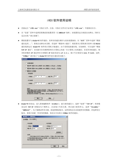
iVEX软件使用说明★直接运行“iVEX.exe”可执行文件,注意:可执行文件名字必须为“iVEX.exe”,不能修改名字;★从“设备”菜单中选择需要测试的装置类型(以DMR201P为例),该装置的运行画面自动弹出,同时右边会出现“演示面板”;★模拟装置可与SCADA-NT软件通信,其所有的通信规约与实际装置兼容;从“编辑”菜单中选择“模拟通信选项。
”,系统自动弹出对话框。
若选择“模拟串口通信”,则需要从计算机相关的串口接RS232通信线到运行SCADA-NT软件的计算机才能通信,由于需要连接通信线,比较麻烦。
可以选择“模拟TCP/IP通信”,该功能可在局域网的两台计算机之间或一台计算机上实现通信。
若采用本机通信,则本机参数的IP地址和对方参数的IP地址均设为127.0.0.1,端口号分别设为5101和5100。
这样,“VCEMLU”就具备了与SCADA-NT软件进行通信的功能了。
★SCADA-NT的设定:进入系统编辑软件(SysEdit),建立新的通信口,选择“标准”“TCP/IP”,将参数设定的TCP/IP参数设为下图所示。
注意端口号的互换。
然后建立新的单元,选择“ThinkBoy”“DMR201P”,为了能测试所有功能,请选择测试版本,这样系统会自动创建所有的数据。
若选择发行版本,系统只创建一些常用的数据。
保存后可实现与VCEMLU软件的通信。
★演示面板的使用:上部是装置的出口继电器KH1~KH6;左边是交流电流电压输入,可设幅值和相位,输入分“正常状态”和“故障状态”两种,并且可以相互切换,以测试保护,正常状态和故障状态的实际输入幅值和相位可分别通过“正常状态设定”和“故障状态设定”进行设置,以模拟不同的故障类型,其中在“故障状态设定”的对话框中可设定故障过渡时间,由正常状态切换到故障状态时,数据会从正常状态等比例连续变化到故障状态,由故障状态切换到正常状态时,数据立即变化到正常状态;右边是所有开关量输入(其中IN01直接从模拟断路器接入),其它的控制输入量包括控制电源失电、合闸回路断线、跳闸回路断线、CT断线、PT断线,以模拟各种告警状态;演示面板内置一个模拟断路器,其中的“○”“┃”分别表示外部控制断路器的分闸和合闸。

第一步:上电运行根据不同型号供电电压一定要注意,ETH2232D供电为3.3V,ETH2232AT-5V为5V供电,ETH001有5V供电和宽电压供电版本。
第二步:连接网络常用的连接方式有两种:1)转换器和电脑(用于配置转换器参数)同在一个局域网内(连在同一个路由或者同一个交换机下)。
2)转换器直接和电脑网口通过一根网线(网线对交叉和平行线没有要求,都可以)连接。
这时候电脑有线网卡需要设定一个静态IP,如图:第三步:配置模块参数1)确保模块在运行模式,ETH2232D/ETH2232AT PW管脚悬空,ETH001开关不要打到串口配置模式(我们在这里使用网络来配置参数)。
2)安装最新配置软件,可以问销售人员或技术支持人员索取。
3)搜索设备:点配置软件上面的扫描按钮,即可在左上角方框内搜索到设备,显示的是模块现有IP和MAC地址,如图:扫描按键提示:如扫描不到,可以进行如下检查:a)供电是否正常b)模块是否在运行模式下,而非串口配置模式下c)是否被电脑防火墙屏蔽,关掉电脑Windows防火墙。
4)修改界面上的参数(具体修改按需要进行,后面将有示范设置方法)。
5)将参数下载到转换器。
a)鼠标点击左上角设备MAC地址,点连接按钮(选中一个设备后连接按钮会从灰色的不可控状态转换到可以点击的按钮状态),如图:b)点连接后,会出现“配置”按钮,点击“配置按钮”参数会下载到转换器(因为下载采用的是UDP广播而导致偶尔会提示出错,这种情况只需要重新点击配置进行下载即可),如图:第四步如何测试串口转以太网数据传输1)如何配置转换器的IP地址等参数本地IP:即分配给转换器的IP地址,转换器在工作的时候使用这个IP和网络里面其它设备进行通信。
子网掩码:A类IP子网IP为:255.0.0.0,B类IP子网为:255.255.0.0,我们通常使用的C类IP子网为:255.255.255.0网关地址:即转换器所在网络的路由的IP地址远程IP:远程IP即目标IP,是转换器工作在客户端时需要连接的远程服务器IP配置举例(电脑和转换器在同一个路由下面):可以通过电脑知道网关地址,如图。
串口以太网服务器用户手册(使用前请先阅读本手册)版本号:2.0.1重要声明本公司将尽可能地提供本系列产品可靠而详尽的资讯,努力使本手册中提供的信息准确和适用,然而本公司并不对这些信息的使用承担任何责任,也不对这些信息的使用承担任何连带责任。
本公司并无义务提供此系列产品详尽的应用资讯,或对因非法使用本系列产品所遭受的损害负任何责任。
本公司保留在不事先通知情况下更改本使用手册全部或部分内容的权力。
由于产品和技术的不断更新、完善,本资料中的内容可能与实际产品不完全相符,敬请谅解。
如需查询产品的更新情况,请查询本公司网站或直接与本公司业务代表联系。
商标&著作权本书提到的所有公司商标、商标名称及产品名称分别属于该商标或名称的拥有者所有。
1目录一、产品介绍 (3)1、产品概述 (3)2、简明特点 (3)3、外形图及指示灯说明 (4)4、引脚定义 (6)二、产品应用 (8)1、应用概述 (8)2、跳线说明 (9)3、接线说明 (9)4、设备配置 (11)5、设备应用 (16)1)通信帧说明 (16)2)使用方式 (17)6、安装尺寸 (19)7、常见故障排除方法 (19)三、选型指南 (21)1、电源配置 (21)2、产品型号定义 (21)2一、产品介绍1、产品概述重要设备联网是工厂企业发展的趋势。
串口以太网服务器的主要功能就是将标准的串口总线数据(RS-232、RS-422、RS-485)与标准的支持TCP/IP协议的以太网数据进行双向转换,用来解决普通串口设备在Internet/Intranet上的联网问题。
串口以太网服务器系列包含如下几种型号:型号说明单串口-A 一路串口信号与以太网的双向转换,非隔离型单串口-B 一路串口信号与以太网的双向转换,隔离型双串口-A 二路串口信号与以太网的双向转换,非隔离型双串口-B 二路串口信号与以太网的双向转换,隔离型以上几种型号大部分功能与特性是一致的,有不同的地方会特别说明。
前言感谢您购买Siemens Energy Subsea 产品。
本文档涵盖DigiTRON 连接器产品系列的保护、存储、运输、开箱、部署和维护相关信息。
重要信息请在使用前仔细阅读请妥善保存,以供日后参考修订摘要本页记录了整个文件的修订状态及其发行授权。
版权所有 © 2020 Siemens Energy Subsea Connectors(Siemens Energy plc 的一个分部),Subsea Excellence Centre, Ulverston, Cumbria, LA12 9EE, England。
版本编制人日期批准人发布日期受影响的页面/备注7 R Wyatt 2020 年 11月 9 日R Wyatt 2020 年 11 月9 日更新了第 1 节的 IOM 列表6 R Wyatt 2020 年 6月 26 日E Chaize 2020 年 6 月26 日更新为新的 IOM 模板,明确确定了产品安全建议。
新增了 DigiTRONe 和 DigiTRON3。
新增了有关盖子和占位连接器的章节。
新增了备选测试连接器(来自 IOM-002-CAM,因此此 IOM 可以作废)。
5 R Wyatt 2020 年 2月 21 日J.Hardisty 2020 年 2 月21 日增加了有关不用于固定压力容器装置的额定压差产品的安全警告。
4 P.Westwell 2014 年 11月 27 日B.Leach 2014 年 11 月27 日更新了偏离公差,增加了第 5 节的警告事项。
3 P.Westwell 2014 年 4月 29 日B.Leach 2014 年 4 月29 日新的设计封面和重新创建整个文件格式。
2 P.Westwell B.Leach 2014 年3 月12 日重新创建格式、各种文本修改,1 P.Westwell B.Leach 2013 年 8 月1 日第一版目录1本手册涵盖的产品 (6)2基本信息和快速参考 (7)2.1产品概览 (7)2.2产品规格和认证 (8)2.3 联系信息和反馈 (9)2.4 产品建议标签 (9)2.5 产品标志 (10)2.6 CE 标签/标志 (10)2.7 产品示例 (10)3产品安全 (12)3.1 与操作相关的警告 (12)3.2 预期用途 (12)3.3 一般安全信息 (13)3.4 相关文档 (16)3.5 危害健康物质管制条例 (COSHH) (17)4缩写 (18)5规格 (19)5.1连接器规格 (19)6准备产品的使用或储存 (21)6.1 产品保护和包装 (21)6.2 开箱 (22)6.3 存储、保护和使用寿命终止 (22)7安装和装配 (24)7.1 阴极保护 (24)7.2 安装设备 (24)8正常运行和故障状态期间的用户信息 (34)8.1视觉/声音信号 (34)8.2 正常和故障/危险操作 (34)8.3 故障排除 (34)9产品操作与维护 (35)9.1 安全注意事项 (35)9.2 产品维护和保养 (35)9.3 插座触点插针的水下保护 (35)9.4 产品保护;端盖和占位连接器 (36)9.5 带电插拔 (37)9.6 去除海洋微生物和钙沉积物 (38)9.7 产品测试 (38)9.8 插接产品前的检查 (38)9.9 ROV 连接器的插拔 (38)9.10 插板连接器的插拔 (41)9.11 潜水员操作连接器的插拔 (41)10客户意见/反馈 (43)表格表 1 与 DigiTRON 产品系列相关的其他安装、操作和维护手册列表 (6)表 2 DigiTRON 产品系列标识 (7)表 3 DigiTRON 产品规格和认证 (8)表 4 DigiTRON 产品联系信息 (9)表 6 产品故障排除联系信息 (34)图示图 1 产品建议标签 (9)图 2 DigiTRON 产品上的产品标志 (10)图 3 典型法兰安装连接器 (10)图 4 典型 ROV 穿板式连接器 (11)图 5 典型的飞线型和法兰型 ROV 占位连接器 (11)图 6 典型的潜水员操作占位停车连接器 (11)图 7 可接受的装运包装 (21)图 8 不可接受的包装和存储 (21)图 9 典型插板连接器 (25)图 10 插板连接器的法兰类型 (26)图 11 典型穿板式 ROV 连接器 (28)图 12 ROV 穿板式连接器剖视图 (28)图 13 典型兼容法兰安装型 ROV 连接器 (29)图 14 兼容法兰安装 ROV 插头的安装 (29)图 15 兼容法兰安装连接器的安装和部件剖视图30图 16 显示 ROV 兼容安装法兰文本的视图 (30)图 17 密封式隔板 Diver Mate 插头连接器 (31)图 18 典型的法兰安装占位停车连接器 (32)图 19 测试连接器,ROV、潜水员和插板型 (33)图 21 ROV 型运输保护盖(左)和保护盖 (36)图 22 ROV 型水下保护盖 (37)图 23 ROV 型水下环境防护盖和占位连接器(飞线型和法兰型) (37)图 24 对齐标记和唇形密封配合指示器 (39)图 25 ROV 拔出工具,零件号 BQ-30090-00 (40)图 26 潜水员操作型连接器(显示插接特性) (42)1 本手册涵盖的产品本手册涵盖有关DigiTRON 单连接器的信息,包括其电气和机械规格。
NETCOM-100IE+以太网转串口设备修订历史目录1. 产品简介 (1)1.1产品概述 (1)1.2产品特性 (1)1.3产品规格 (1)1.3.1电气参数 (1)1.3.2工作温度 (2)1.3.3防护等级 (2)1.3.4机械尺寸 (2)2. 产品硬件接口说明 (3)2.1面板布局 (3)2.2电源接口 (4)2.3按钮 (4)2.4LED状态指示灯 (4)2.5以太网接口 (4)2.6串行接口 (5)2.6.1RS-232模式 (5)2.6.2RS-485模式 (5)2.6.3RS-422模式 (6)3. 工作模式 (7)3.1TCP Server模式 (7)3.2TCP Client模式 (7)3.3Real COM模式 (8)3.4UDP模式 (8)3.5DISABLE模式 (9)4. 配置参数的功能和含义 (10)4.1本地网络参数配置 (10)4.2工作串口参数配置 (11)5. 快速使用说明 (13)5.1各模式快速使用基本步骤 (13)5.1.1TCP Server模式 (13)5.1.2TCP Client模式 (19)5.1.3Real COM模式 (21)5.1.4UDP模式 (26)5.1.5DISABLE模式 (33)6. WEB网页配置 (34)6.1登录网页配置系统 (34)6.2系统参数配置 (35)6.3串口参数配置 (35)6.4系统工具 (36)7. 附录 (38)A.1TCP和UDP中默认已经被占用的端口列表 (38)产品问题报告表 (40)产品返修程序 (41)免责声明 (42)1. 产品简介1.1 产品概述NETCOM-100IE+是广州致远电子有限公司开发的一款TCP/IP以太网转串口设备。
它内部集成了TCP/IP协议栈,可以轻松完成嵌入式设备的网络功能,使得嵌入式系统设计更加简洁方便,极大地提高了开发效率,大大缩短了产品的开发周期,使产品能够更快投入市场,明显增强产品的市场竞争力。
单串口- ETH001(带外壳)
宽电压(9-48)供电
图一
核心模块
图二
一ETH001功能简介
ETH001(升级版)是一个串口转网络的联网转接设备—高端工业级串口服务器,它使用我们公司十年来主推的模块ETH2232D为核心模块。
该模块内部集成了硬件TCP/IP协议栈、socket编程实现,全透明传输,串口波特率高达230kbps。
该核心模块长期使用于银行加密和铁路等专属行业,稳定性和可靠性得到了长时间的验证。
ETH001正是我们基于此款高性能的模块而推出的一款完整的联网转接产品。
用户可以利用它轻松的完成设备串口到网络的联网升级,可以大大节省产品研发成本和时间。
使产品更快的投入应用,一鸣惊人。
功能特点:
●10/100M网络接口。
串口最大波特率230400bps。
●工业级高稳定性可靠性。
●可以轻松利用网口或者串口进行参数配置。
●TCP服务器,TCP客户端,UDP,MODBUS网关工作模式。
●支持动态IP(DHCP),或静态设置IP地址。
●内嵌模块尺寸小。
●支持自动极性转换(MDI/MDIX)。
●内部32kByte存储作为TCP/IP通信缓存。
●宽电压9-36V或者5V供电系统。
●功耗少于250MA。
●支持串口和485传输同时支持RTU转modbus TCP IP。
●支持固件现场可升级可以为客户订制合适的通信协议
●支持跨网段扫描配置(可以在忘记设备参数的情况下轻松读取和配置参数)
二ETH001硬件说明
ETH001接口包括通信所需要的网口、串口、485等接口,同时包括电源的开关和复位功能,明确的LED灯指示,同时包含一个功能强劲的选择功能,可以实现设备的串口配置网络配置以及固件升级功能。
三硬件连接使用说明
设备的硬件连接非常方便,只需简单的供电,网络和串口、485的连接即可,网线支持交叉平行自适应,大大方便了工程现场的设备安装。
四接口详细说明
串口DB9:公头针型
我们的串口和电脑连接使用交叉的串口线。
与设备连接时请注意
连接的对应顺序,以免因为2、3脚的错位而造成设备无法正常通信485接口
A 为+(正)B为-(负)
如果设备上是NC 短接为120欧阻抗
如果设备上是G R
G 地GND
R 短接R—A/+ 为120阻抗
请按照正确连线连接
从左到右依次:
1 电源插头请根据标签的指示电压供电分为9-36V宽电压
内正外负
2 电源端子正负请参看标签+为正–为负
3 功能选择—正常通信请拨到上面
BOOTEN :拨到下面为固件升级功能方便客户现场协议处理
PW:拨到下面为通过串口配置设备参数信息。
注:网口配置不需要拨动PW 在设备运行时随时配置4 RJ45网络连接传输指示灯
设备简单测试步骤
1 设备网线直接连到pc机
测试前的准备:
1设备网线插到pc机网口—普通能上网的网线即可
2 连接串口到电脑---如果是DB9串口线请用交叉线连接。
3 给PC机设置一个固定ip,为了确保测试能顺利完成请按照我们的图示设置:
4 给设备供电9-36v或者5V 按照所购设备供电说明供电
配置设备参数信息:
安装设备配置软件打开配置软件:
点击扫描:
更改我们要更改的设备参数主要是ip地址串口波特率端口号工作模式等
更改如图:
串口信息:主要是改了波特率9600 和端口号10000 IP地址测试默认18 服务器模式
配置参数我们这里通过网口配置设备支持通过串口和网口两种方
式配置所有的参数信息一般使用网口
选中扫描到得IP左上角点击连接点击后连接变为配置
点击配置:等配置完成点击读取配置查看配置信息是不是我们配置的
测试通信:
串口到网络的测试
串口对应的网络端口号是10000 服务器模式IP 192.168.0.18 波特率9600
打开调试助手TCP调试助手和串口调试助手按照我们的配置填写数据如图
打开串口和连接网络
打开后如图测试通信:
2 设备网线连接到路由
对于网络设备来说连到路由和直连电脑的通信测试是大同小异的,具体的步骤请参看前面直连电脑的测试这里我们要注意的是如果是连接到路由IP地址子网掩码网关这三个信息要符合局域网路由的设定,1 网关和子网掩码要设置成和你局域网电脑一样
2 IP最后一位要设置成和你的局域网所有电脑不一
样的数值以免冲突
简单说IP信息的配置就像您增加了一台电脑要实现上网的
IP配置规则即可
这样通信测试完成如果测试通信的时候遇到连接不上或者通信不上请断电复位一下设备
虚拟串口的使用VCOM3
如果您没有涉及到这个的使用,可以直接跳过。
如果您需要这个功能,那么请您先会上面的通信操作,因为如果您上面的操作还没搞懂,这个会使您的测试过程更加不可理解,也不可能成功。
在上面的基础上上面测试的是网络—串口现在我们是串口—串口。
也就是说要用网口虚拟一个串口。
1 保持上面的操作把网络那部分断开我们现在把网络虚拟成一个串口。
2安装第三方虚拟软件《vcom3虚拟串口软件》如果您没有请和我们的技术支持人员索要。
3 安装完后打开—
4
我们配置的是服务器所以选第一个确定
5
6
删除后
7
8
9
10 好了这样我们的电脑就多出了一个com6口,我们打开串口工具选择com6打开,这样就是完成了虚拟串口,就可以测试通信了
设备的实际应用
通过前面的操作我们已经知道了设备的功能和具体通信测试方式,这样我们就可以连接到我们设备进行通信测试了。
硬件连接
如果您是串口的设备请连接到我们设备的串口连接线序请按照您的设备串口顺序和我们设备串口顺序正确连接以确保通信正常进行。
如果您是485设备,请按照A正B负的规定A-A B-B连接起来。
设备上电连接上网络这样硬件连接就完成了。
设备参数的配置
网络参数可以保持前面测试设备的参数不变
串口参数请配置成您自己设备串口或者485端口相同的波特率数据位停止位奇偶校验位即可。
如果需要用虚拟串口请按照前面的步骤设置这样你就可以用您自己的设备控制软件或者直接发设备能反映的命令进行测试了
核心模块型号ETH2232D。