GMN电主轴使用说明书_手动换刀型_cn
- 格式:pdf
- 大小:1.65 MB
- 文档页数:78
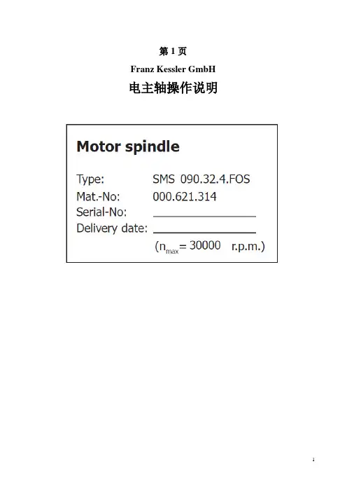
第1页Franz Kessler GmbH 电主轴操作说明第2页目录EC制造商声明 (3)注意 (4)预期使用 (4)安全说明 (5)安全运输 (5)安全装配和维修 (6)安全检查 (6)永磁性转子的安全处理 (6)安全操作 (7)储存 (8)装配 (9)准备工作 (9)机械连接 (9)连接电路 (9)连接传感器 (9)电动机绕组温度传感器(S7) (9)速度和位置测量传感器(S5/S6) (10)刀具夹紧监测(S1-S3) (11)主轴与电机冷却 (12)冷却润滑回路 (13)连接 (13)时间顺序 (14)松夹钳单元的液压连接 (15)气动连接 (16)油气润滑 (17)投入运行 (18)退役和拆卸 (19)重要操作说明 (20)维护 (21)主轴刀具 (21)旋转传动单元 (21)刀具夹紧系统 (23)更换零件 (24)更换夹紧装置 (24)更换旋转传动单元 (26)更换渐近开关 (27)备件 (28)故障表 (28)故障检查表 (30)第3页EC制造商声明产品名称:交流电主轴类型: SMS090.32.4.FOS对上述提及的产品,我们作为制造商确认符合以下标准:• EN 60 034-1 ,评级• EN 60 034-5,各类保护• EN 60 034-6 ,冷却的方式• EN 60 034-9 ,噪声限值• EN 602041,机床安全上述产品是组件不能独立投入运行,只能被安装在预定的机床或工厂(最终产品)才能运行。
包括上述产品的最终产品还必须符合EC发布的声明标准。
在调试终端产品前必须检查它是否符合指令98/37/ECE.herwanger(经理)Franz Kessler GmbHFranz-Kessler-Straße 2D – 88 422 Bad Buchau (Germany)第4页注意在应用电主轴之前,必须仔细阅读该文件。
通过了解这些作业的指示,才能避免主轴故障和确保无故障工作。
大型数控加工中心使用说明正天恒业数控目录自动换刀雕刻机的使用说明 (3)自动换刀雕刻机新代系统常用参数设定表 (12)使用 GHOST 制作系统卡(DOS) (14)自动换刀雕刻机的使用说明以下为工作步骤:1.把主控制箱的总开关扳到ON状态,此时控制箱红色电源指示灯亮。
2.按下控制箱面板的驱动器电源绿色按钮、变频器电源绿色按钮,使其处于上电状态。
检查气路压力要达到6bar,气缸吸合,除尘毛刷气缸处于行程的上部。
3.SYNTEC控制系统上电,进入界面后,提示:X、Y、Z轴尚未回机械原点。
如下操作完成回机械原点:先按(键左上角灯亮),再按、、,此时雕刻机的XYZ方向往设定的机械坐标零点位置移动,直到面板界面里边机械坐标各轴都显示0,证明回机械原点动作完成,X回到最左边,Y回到最前面,Z上升到顶部。
如下图:回机械原点时出现问题处理方法:故障现象:回机械原点方向反。
原因是限位感应器始终处于触发状态,检查感应器触发信号。
4.把要使用的刀具安装到刀具夹头,并用手放到刀具库中:如下图刀具排列的循序为左边是第一把刀(系统默认为T1), 以此类推。
从左到右依次为T1, T2,T3, T4, T5, T6, T7, T8.如下图:放上加工材料,按下开启真空吸附泵的绿色按钮吸附住材料,按下开启吸尘泵绿色按钮。
5. 加工开始之前需要设定机器的X Y Z 三轴的工作原点(工件原点):先手动将刀具头装上主轴(一般是程序中的第一把刀),按(键左上角灯亮),再通过按X+, X-,Y+, Y-,Z+ Z- ,如图把机头移动到雕刻物件的左下角,既该图案路径的零点位置。
精确定位需要用手轮时,操作如下,先按下灯亮,手轮模式已启动。
通过手轮进行精确定位,主轴运行到加工物件的左下角的状态。
在系统控制器当前界面,如下操作→(Position)→(Workpiece Coor)→移动方向键,使光标移动到需要设置的G54-G59对应的X、Y坐标→(tched),如下图:再继续设T1的Z工件原点,回初始界面,选,再选,界面如下,把光标移动到序号01(即对应T1)Length列输入对应机械坐标,即完成T1Z轴的原点设定。
电主轴操作及维护(MAKINO)1.特点2.注意事项2.1电主轴启动时注意事项2.2电主轴操作时注意事项2.3操作结束时注意事项3.操作3.1刀具夹紧/松开3.2旋转速度指令3.3主轴启动/停止3.4主轴准停3.4.1主轴准停的调整4. 主轴检查4.1 主轴锥体清洁4.2 主轴润滑检查4.3 压缩空气压力检查4.4 芯轴密封O型圈检查4.5 夹头及套管的润滑5. 主轴调整与维护5.1 LS, SOL 的功能5.2 LS,SOL的布置图5.3 刀具夹紧/松开的机械妆态5.4 LS的调整5.4.1 LS00的调整5.4.2 LS01的调整5.4.3 LS601和LS602的外形5.4.4 LS601的调整5.4.5 LS602的调整5.5 更换芯轴O形圈的步骤5.6 更换刀具夹紧装置的步骤5.6.1 结构5.6.2 更换步骤5.7 主轴单元更换步骤.见维修工段编撰的《电主轴更换工艺》6.故障处理6.1 主轴旋转过程中急停按钮被按压6.2 主轴不能启动停止6.3 主轴速度或主轴启动/停止时间不正常6.4 主轴准停故障6.5 刀具松开不能执行6.6刀具夹紧不能执行6.7 主轴旋转过程中有噪音6.8 主轴油渗漏1. 特点电主轴有如下特点●装电机直接驱动主轴●中心冷却主轴冷却油由温度控制系统进行冷却,从主轴尾部注入主轴部,冷却油从尾部流出后,将从外部冷却轴承的外表面,和电机。
●刀具占位检测当换刀时,LS601检测刀具是否装夹到位。
2. 注意事项2.1 电主轴启动时注意事项●设备启动前应检查冷却油(润滑)的液位是否符合要求。
当没有足够的冷却油(润滑)提供给主轴时,将出现轴承咬死,或其它问题。
●主轴启动后在转速达到3000—5000min-1时应预热超过5分钟,由于主轴从停止到从新启动,主轴需要在预热期间对轴承进行均匀的润滑。
●应确认通冷却液的芯轴O型密封圈是完好无损的。
Fig.H.1 主轴2.2电主轴操作时注意事项●确认刀具装夹到位,这一功能由LS602开关进行检测,通过LS602开关检测刀具装夹是否到位,可以防止主轴旋转时不平衡,或者防止轴承咬死。
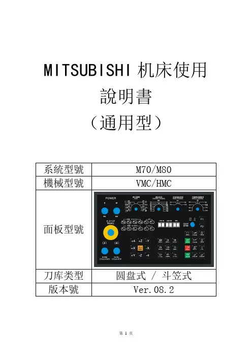
MITSUBISHI机床使用說明書(通用型)系統型號M70/M80機械型號VMC/HMC面板型號刀库类型圆盘式 / 斗笠式版本號Ver.08.2目錄第一章機床使用前注意事項1.1 電氣規範第一次啟動前注意事項機床用電安全機床操作注意事項1.2 機床接地及注意事項1.3 開機/關機順序開機操作順序關機操作順序機械原點複歸2.4 緊急停止及恢復第二章操作面板2.1 機械操作面板外觀圖2.2 機械操作面板功能說明A. 電源及緊急停止區B. 模式選擇區C. 軸的移動以及速度/倍率選擇區D. 主軸控制區E. 自動操作功能區F. 周邊功能區G. 警示燈區H. 指示燈區第三章M功能代碼表第四章異警排除附錄 A ATC設定與調整A、刀臂式刀庫ATC調整1. Z軸換刀點的調整2. 主軸定位點的調整3. 刀庫分解動作說明B、斗笠式刀庫ATC調整1. Z軸換刀點的調整2. 主軸定位點的調整C、刀具表重新排列步驟附錄 B I/O列表附錄 C 掃描面板地址表第一章機床使用前注意事項1.1 電氣規範本機床目的是用於金屬切削。
例如銅、鐵、不銹鋼、鋼、鋁以及鋁合金屬。
其他金屬或用途是不允許的。
而且不適合使用在易燃物質或硬脆材質如鎂、陶瓷、木頭、玻璃和有毒物質等。
假如有任何標準問題,為了防止人員的安全和保障貴公司的權益,請和本公司聯絡。
第一次啟動前注意事項●操作前請仔細閱讀本書和數控系統的使用手冊●由於經過運輸過程中的顛簸,拆箱後請先檢查XYZ三向的運輸固定裝置是否完好,檢查主軸箱與配重錘之間的連接件是否牢固可靠。
●在機床運行之前,必須檢查XYZ三向及主軸箱和配重錘的運輸固定架和固定螺釘是否已全部拆除。
●首次啟動機床或停用較長時間後,再次啟動機床時,打開電源後,應等待15分鐘,待機床充分潤滑後,再操作機床。
●在機床首次使用前,必須將主軸打刀用增壓缸的油杯注滿液壓油,並排除缸體中的氣體,以確保打刀的可靠性及打刀力,從而避免損傷機床及人員。
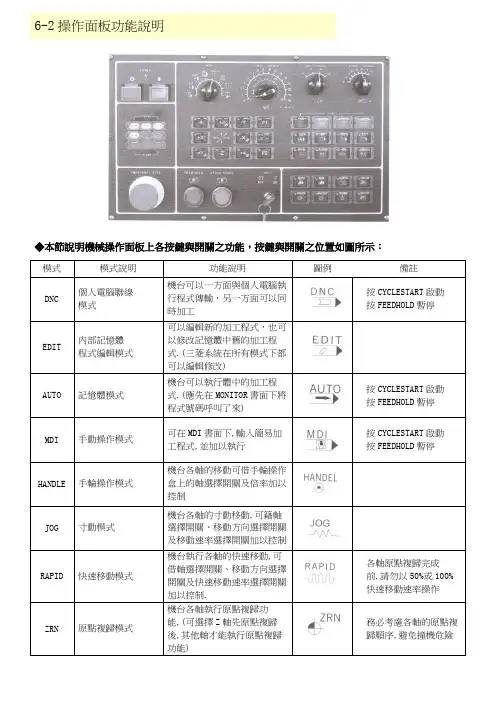
6-2操作面板功能說明◆本節說明機械操作面板上各按鍵與開關之功能,按鍵與開關之位置如圖所示:模式模式說明功能說明圖例備註DNC 個人電腦聯線模式機台可以一方面與個人電腦執行程式傳輸,另一方面可以同時加工按CYCLESTART啟動按FEEDHOLD暫停EDIT 內部記憶體程式編輯模式可以編輯新的加工程式,也可以修改記憶體中舊的加工程式.(三菱系統在所有模式下都可以編輯修改)AUTO 記憶體模式機台可以執行體中的加工程式.(應先在MONITOR書面下將程式號碼呼叫了來)按CYCLESTART啟動按FEEDHOLD暫停MDI 手動操作模式可在MDI書面下,輸入簡易加工程式,並加以執行按CYCLESTART啟動按FEEDHOLD暫停HANDLE 手輪操作模式機台各軸的移動可借手輪操作盒上的軸選擇開關及倍率加以控制JOG 寸動模式機台各軸的寸動移動,可籍軸選擇開關、移動方向選擇開關及移動速率選擇開關加以控制RAPID 快速移動模式機台執行各軸的快速移動,可借軸選擇開關、移動方向選擇開關及快速移動速率選擇開關加以控制.各軸原點複歸完成前,請勿以50%或100%快速移動速率操作ZRN 原點複歸模式機台各軸執行原點複歸功能,(可選擇Z軸先原點複歸後,其他軸才能執行原點複歸功能)務必考慮各軸的原點複歸順序,避免撞機危險◆軸的移動方向移動速率選擇開關名稱功能說明圖例有效模式JOG/FEEDRATE OVERRIDE各軸的寸動及切削移動速率選擇開關,JOG模式下各軸的移動速率 mm/min為單位,DNC/AUTOMDI等模式以%為單位JOG/DNC/AUTO/MDIRAPID OVERRIDE 快速移動速率選擇開關RAPID/ZRN/DNC/AUTO/MDI+X +X 軸的移動方向選擇按鈕開關JOG/RAPID/ZRN-X -X 軸的移動方向選擇按鈕開關JOG/RAPID/ZRN+Y +Y 軸的移動方向選擇按鈕開關JOG/RAPID/ZRN-Y -Y 軸的移動方向選擇按鈕開關JOG/RAPID/ZRN◆軸的移動方向移動速率選擇開關名稱功能說明圖例有效模式+Z +Z 軸的移動方向選擇按鈕開關JOG/RAPID/ZRN-Z -Z 軸的移動方向選擇按鈕開關JOG/RAPID/ZRN+4 +4 軸的移動方向選擇按鈕開關JOG/RAPID/ZRN-4 -4 軸的移動方向選擇按鈕開關JOG/RAPID/ZRN◆主軸控制功能開關名稱功能說明圖例有效模式SPENDLE OVERRIDE 主軸旋轉轉速調整DNC/AUTO/MDT SPINDLE CW 主軸CW旋轉HANDLE/JOG/RAPID/ZRN SPINDLE STOP 主軸停止旋轉HANDLE/JOG/RAPID/ZRN SPINDLE CCW 主軸CCW旋轉HANDLE/JOG/RAPID/ZRN SPINDLE ORT 主軸定位HANDLE/JOG/RAPID/ZRN◆自動操作功能開關名稱開關說明功能說明圖例CYCLE START 程式啟動啟動程式的執行.(應先在MONITOR 書面下將程式號碼呼叫出來)。

YG62-60L使用说明书目录一、产品概述 (1)▷产品简介 (1)▷产品用途 (1)二、主轴外形图 (2)三、技术参数表 (3)四、电机特性曲线 (4)五、主轴安装说明 (5)▷测温传感器及其阻温特性对照表 (6)▷循环冷却系统说明 (8)▷换刀装置的控制 (8)▷空气密封及主轴吹尘的控制 (8)▷压缩空气气体质量要求 (9)▷跑合程序说明 (9)▷主轴驱动要求 (9)▷主轴安装要求 (10)六、使用注意事项 (11)▷主轴装机过程注意事项 (11)▷启动注意事项 (11)▷维护和保养注意事项 (12)一、产品概述▷产品简介1.本主轴为电机内装式主轴, 内置三相交流异步感应电机, 有变频器进行无级变速控制。
由于本主轴具有结构紧凑、重量轻、惯性小、振动小、噪声低等特点因此能够实现高转速, 高精度及高运转稳定性。
2.本主轴轴承采用油脂润滑陶瓷复合球轴承, 可在轴承的使用寿命周期内实现终生润滑3.本主轴使用强制冷却的方式对电机、前后轴承进行冷却。
冷却液流经主轴机体合理布置的循环水道带走主轴高速旋转产生的热量, 达到热平衡, 使电主轴的温度恒定在一定值内。
外置的冷却装置: 保持冷却液的温度恒定。
4.本主轴内置PTC130测温传感器( 其技术参数详见本说明书其它章节) , 如需进行对电机做温度保护时能够读取。
5.刀具加紧方式: 本主轴内置自动换刀装置, 刀柄形式为直接换刀, 标配为ф6, 可选配ф4, ф3.175.▷产品用途本产品为基础主轴, 主要用于雕铣机或加工中心进行有色金属、黑色金属、玻璃、石墨等材料的加工。
二、主轴外形图三、技术参数表20 电机绕组耐压试验1500V/min四、电机特性曲线▷功率、扭矩-转速曲线▷电压-频率曲线五、主轴安装说明▷测温传感器技术参数1.传感器类型: PTC(正温度系数), 常温阻值R25≤255Ω2.开关特性: 温控点Tk=130℃,Tk-5≤1650Ω,Tk+5≧4200Ω偏差△T=±5℃, Tk重复性△T=±0.5℃4.热动作时间: ≤2S5.最大工作电压30V(DC),绝缘强度2.5KW6.最高允许存放温度180℃, 最低允许存放温度-25℃▷循环冷却系统说明◆水冷要求: 推荐使用蒸馏水, 同时推荐使用费诺克斯( Femox) 保护剂F1(使用配比1:200).冷却液的温度建议为24℃-28℃, 当不能达到时, 应该与环境温度基本一致, 进水管、回水管温差不超过5℃◆一般在冷却系统的回水管中设置流量开关, 以便控制冷却液的流量, 确保主轴冷却液的正常供给。
电主轴使用说明电主轴是一种高速高刚度精密的电动机,其由精密滚动轴承支承,油脂润滑,外循环水冷却,雕刻(铣)主轴一般为立式使用,使用的方法正确与否将直接影响雕刻和雕铣质量,以及主轴的工作寿命。
1、避免撞击强烈撞击,特别是主轴端部及前端盖部位绝不许撞击,否则会损坏精密轴承及主轴精度,造成主轴回转精度的丧失。
2、正确安装和夹紧安装前应确认主轴电机状态正常,主要指外观无损伤,主轴转动轻匀。
用500V摇表查定子之对地绝缘电阻在100мΩ以上。
主轴电机套筒外径与夹持座孔间的配合公差必须保证主轴电机之套筒能顺利滑入座孔,在任何情况下都不能使用锤子或其他工具来使主轴定位,夹紧力不宜过大,否则会造成精密轴承的钢球滚道变形,使主轴精度及寿命受到影响。
夹持后要检查主轴前端锥孔定心面的跳动应不大于0.005MM,主轴回转轻匀。
3、筒夹(ER型)压帽和刀具的安装刀具的安装必须保证回转精度,否则会产生剧烈振动,影响雕刻(铣)质量和效率及轴承寿命。
必须十分小心的地擦净筒夹,压帽和刀具以及主轴前端之锥孔,装拆刀具应避免用力过猛。
组装后要查看刀具根部跳动﹤0.015MM若超差要通过反复放松和拧紧并调整变换刀具柄接触面来纠正,若无改善要检查各接触面是否处于正常状态,切忌乱敲打。
4、启动前必须1)确认主轴套筒所须的循环冷却水已开通,冷却水的温度一般不要超过35°c,但也不宜过低,不宜直接接用自来水,因水温过低会造成主轴电机内部热空气遇冷而形成凝水影响绝缘和轴承生锈,冷却水流量一般可在3-5L/MIN,冷却水应干净无杂屑以防堵塞通道。
冷却水箱中水量约50L—100L,建议水泵用AB-25或AB-50。
进出水口不能相距太近,必须使水在箱内有一冷却过程,力求使进出口水温差能达到2—3°c,要避免造成热水循环而达不到冷却效果。
2)确认电源电压,频率与主轴匹配关系正确,按主轴名牌数据或产品检测报告中提供的电压与频率对应关系设置变频器的U/F 曲线,主轴插头座的1号芯接地,2.3.4号芯接变频器的U V W。
主轴电机购买技巧买主轴电机的时候要看好以下几点:1、电主轴特性有恒转矩和恒功率两种,恒功率的贵些,雕刻机主轴采用恒转矩比较合适;2、种类有风冷和水冷,风冷主要是早期几百瓦的小功率主轴,现在雕刻机上基本上都是使用的水冷式电主轴,功率大噪音小;3、润滑方式有油雾和油脂,24000转以上的高转速电主轴采用油雾,由专门油路供油,安装使用复杂;雕刻机大多采用油脂润滑,转速可在6000-24000转左右变频调速;4、支撑方式有2轴承、3轴承和4轴承,3、4轴承适合雕刻钢材等重载荷1.5kW以上主轴采用较多,一般软金属采用2轴承轴承够用;5、主轴芯架有铝合金和不锈钢焊接形式,目前大多的主轴芯架采用的是铝合金,重量轻,但是体积大,现在有一些新产品采用不锈钢焊接芯架,同功率下可以缩小主轴尺寸,如通常1.5kW主轴的体积为Φ80×215mm左右,不锈钢焊接芯架主轴新产品可以做到Φ65×210mm左右,更适合雕刻机使用,不过价格贵一二百元钱;6、选择变频器功率要比主轴功率大些,这样能充分发挥主轴的输出功率,1.2kW主轴配1.5kW变频器,1.5kW主轴配2.2kW变频器。
主轴电机常见故障及排除方法主轴电机的维修注意事项1、主轴电机运行中发现声音或振动异常,应停机检查轴承,是否损坏,必要时更换新轴承,运行中发出异常气味,或停机切断电源,用兆母表插电机定子电阻,如电阻为0示为烧坏,应更换定子线圈。
2、主轴电机定期更换润滑脂,油脂为特种高速锂基润滑脂。
3、主轴电机轴承为精密工件,拆装时作用力不能直接作用轴承的滚珠上,外圈上,即在主轴上拆装轴承时,力应作用在轴承内圈上,以免降低轴承精度影响寿命。
4、清洗轴承时先93#标号浸15分钟后,用毛刷刷洗衣,每次应用清洁的清洗三次以上,严禁在未清洗干净时转动,待凉干后加入高速锂基润滑脂,油脂填充量约占轴承空间的20%-50%。
5、装配轴承时,角接触轴承应保证和拆卸时的配置一致(注意:轴承内圈或外圈端面的一边是宽边,别一边是窄边,切勿装错,否则会造成内外圈分离,主轴径向跳动磊,轴承易失损坏。

电主轴使用说明电主轴是一种高速高刚度精密的电动机,其由精密滚动轴承支承,油脂润滑,外循环水冷却,雕刻(铣)主轴一般为立式使用,使用的方法正确与否将直接影响雕刻和雕铣质量,以及主轴的工作寿命。
1、避免撞击强烈撞击,特别是主轴端部及前端盖部位绝不许撞击,否则会损坏精密轴承及主轴精度,造成主轴回转精度的丧失。
2、正确安装和夹紧安装前应确认主轴电机状态正常,主要指外观无损伤,主轴转动轻匀。
用500V摇表查定子之对地绝缘电阻在100мΩ以上。
主轴电机套筒外径与夹持座孔间的配合公差必须保证主轴电机之套筒能顺利滑入座孔,在任何情况下都不能使用锤子或其他工具来使主轴定位,夹紧力不宜过大,否则会造成精密轴承的钢球滚道变形,使主轴精度及寿命受到影响。
夹持后要检查主轴前端锥孔定心面的跳动应不大于0.005MM,主轴回转轻匀。
3、筒夹(ER型)压帽和刀具的安装刀具的安装必须保证回转精度,否则会产生剧烈振动,影响雕刻(铣)质量和效率及轴承寿命。
必须十分小心的地擦净筒夹,压帽和刀具以及主轴前端之锥孔,装拆刀具应避免用力过猛。
组装后要查看刀具根部跳动﹤0.015MM若超差要通过反复放松和拧紧并调整变换刀具柄接触面来纠正,若无改善要检查各接触面是否处于正常状态,切忌乱敲打。
4、启动前必须1)确认主轴套筒所须的循环冷却水已开通,冷却水的温度一般不要超过35°c,但也不宜过低,不宜直接接用自来水,因水温过低会造成主轴电机内部热空气遇冷而形成凝水影响绝缘和轴承生锈,冷却水流量一般可在3-5L/MIN,冷却水应干净无杂屑以防堵塞通道。
冷却水箱中水量约50L—100L,建议水泵用A B-25或AB-50。
进出水口不能相距太近,必须使水在箱内有一冷却过程,力求使进出口水温差能达到2—3°c,要避免造成热水循环而达不到冷却效果。

DMG培训照片文件整理总结(详见机床操作说明书)目录:一.手动拆刀和装刀:1.进入手动模式。
2.按刀具表软件,进入刀具表。
3.打开编辑开关。
4.建刀库刀位以外的刀具。
5.按结束。
6.进入MDI模式。
7.调用刚建立的刀具。
8.按START键执行。
9.显示更换刀具。
10.按开门键,打开工件间门。
11.按换刀键。
12.屏幕T 开始闪烁。
13.旋转按刀按扭,听到有松夹声音。
14.注意刀具的缺口方向,放刀具到位,松开换刀按扭,听到夹紧的声音,松开刀具。
15.刀具在主轴。
16.关闭工作间的门。
17.屏幕显示更换刀具。
18.刀具已经换入。
19.确认换刀完成。
20.换刀结束,二.手动拆除刀库以外的刀具。
1.按MDI 进入2.调用零号刀具。
3.按START 键执行。
4.屏幕显示从轴上取下刀具。
5.按开门键开工作间门。
6.按换刀键。
7.屏幕T 开始闪烁。
8.用手拿住刀具。
9.旋转拆刀旋扭,拆除刀具。
10.关闭工作间的门。
11.屏幕显示 T0 。
12.屏幕显示从轴人取下刀具,按START 键完成拆刀。
三.从刀库装入刀具。
1.按手动按扭,进入手动数据输入。
2.按刀具表软键,进入刀具表。
3.把光标移到要装入刀具的一行。
4.按左边的刀库管理软键。
5.按刀具拆除,6.等待屏幕显示 1。
20(1号刀库,20号刀位),刀库已经准备好。
7.因为只是装刀,并不是真正拆除,所以按中断结束。
8.打开后面的刀库门,放入刀具,注意缺口方向在里面,完成刀库装刀。
2.把光标移到要拆除的刀具的一行。
3.按刀具管理软键。
4.按刀具拆除。
5.屏幕显示(1。
32)一号刀库32号刀位。
6.按中断软键,不清除刀具参数。
7.打开刀库门,拆除刀具。
8.手动清除刀具数据,按结束,完成刀库拆除刀具。
五.标准刀的校正Z零点。
1.把标准刀放入32号刀位。
按MDI 进入。
2.调用32号刀具。
3.按START 执行。
4.调入标准刀具。
5.在刀具表中输入,标准刀的长度和半径。
目录GSK980T数控车床 (1)第一章手动操作 (1)1.1手动返回机床参考点 (1)1. 2手动返回程序起点 (1)1.3手动连续进给 (1)1.4单步进给 (2)1.5手动换刀 (2)1.6主轴运转操作 (3)1.7主轴倍率修调 (3)1.8 MDI运行 (3)第二章程序编辑 (5)2.1进入程序编辑状态 (5)2.2建立新程序 (6)2.3打开已有的程序 (7)2.4编辑程序 (7)第三章数据设置 (8)3.1设置刀补数据 (8)第四章自动运行操作 (8)4. 1启动自动运转 (8)4.2停止自动运转 (8)4.3单段运行 (9)GSK928TC数控车床 (10)第一章手动操作 (10)1.1手动点动 (10)1.2手动单步进给 (11)1.3手动进给速度选择 (11)1.4手动快速进给速度选择 (12)1.5设置程序参考点 (13)1.6执行M功能 (14)1.7手动主轴控制 (14)1.8手动返回程序参考点 (14)1.9手动返回机床参考点 (15)第二章程序编辑 (15)2.1编辑方式 (15)2.2零件程序的建立、选择和删除 (17)2.3零件程序内容编辑 (18)第三章数据设置 (19)3.1设置刀偏数据 (19)第四章自动运行操作 (19)4.1功能键说明 (19)4.2自动运行加工程序 (20)GSK980T数控车床第一章手动操作1.1手动返回机床参考点1.按机械回零键;2.分别按移动轴键、,机床沿选择轴方向移动;3.当轴返回机床参考点后,相应轴的参考点指示灯亮。
当两轴都返回参考点后,参考点指示灯均亮,如下图。
1. 2手动返回程序起点1.按程序起点键;2.分别按移动轴键、,机床沿程序起点方向移动;3.当返回程序起点后,相应轴的参考点指示灯亮。
当两轴都返回后,指示灯均亮,如下图。
1.3手动连续进给1.按手动方式键,屏幕右下角显示文字“手动方式”;2.点击进给倍率或快速进给键,调整机床移动速度。
GMN Paul Müller Industrie GmbH & Co. KGSPINDELTECHNIK Original operating and assembly manualGMN oil-air-lubrication devicePRELUB GP…GMN Operating and assembly manual 106 02 02PRELUB GP / 2013-10GMN Operating and assembly manual 106 02 02 2 Table of contents1Basic notes ..................................................................................................3 2Safety information........................................................................................7 3Mode of operation........................................................................................9 4Transport and storage................................................................................10 5Device description......................................................................................11 6Assembly manual.......................................................................................17 7Start-up......................................................................................................21 8Operation...................................................................................................27 8.1Operational mode.......................................................................................27 8.2Malfunctionen.............................................................................................30 8.3Shut-down..................................................................................................32 9Maintenance ..............................................................................................33 10Disposal.....................................................................................................34 11Technical data............................................................................................35 12 Enclosure (36)12.1 Dimensional drawing (36)12.2 Electric connection (37)12.3 Lubrication scheme (38)12.4 Spare part list and drawing (41)12.5 Control plan (43)PRELUB GP / 2013-10GMN Operating and assembly manual 106 02 02 31 Basic notesUse in accordance with the regulationsThe oil-air-lubrication device is only allowed for industrial use. The oil-air-lubrication device is for delivering the lubricating oil ac-cording to the specification.The oil-air-lubrication device may only be put into operation if it isinstalled in or at another machine and if it is operated together withthe machine.The oil-air-lubrication device may only be used according to thetechnical data (see chapter …technical data“).High-handed structural changes at the oil-air-lubrication device arenot permitted.For damages at machines and persons resulting from that, we donot assume liability.This also belongs to a use in accordance with the regulations:∙ Pay attention to all notes in the operating manual.∙ Carry out all maintenance work.∙ Follow all appropriate regulations for the work safety and accident prevention during all life cycles of the oil-air-lubrication device.∙ Having the required professional education and authorization of your company to carry out the necessary works at the oil-air-lubricating device.Another use or a use beyond can not be considered to be in accordance with the regulations.PRELUB GP / 2013-10GMN Operating and assembly manual 106 02 02 4 Obligation of the operator The operator carries the responsibility for the correct installation, operation and maintenance of the oil-air-lubrication device by qualified and trained staff accord-ing to the manual’s details.In addition to this he is responsible to use the oil-air-lubrication device only in accordance with the regulations.∙ If hot or cold machine parts lead to danger, the customer must se-cure them from being touched. The guards on "moving parts" mustnot be removed.∙ Remove leakages of dangerous material to be conveyed such that people or the environment are not endangered∙ Comply with legal regulations.∙ Eliminate any danger due to electrical energy.∙ A safety data sheet for the current used lubricating oil of oil-air-lubrication device must be provided.Scope of guaranteeGuarantee regarding operational safety, reliability and capacity can only be granted by the manufacturer under the following conditions:∙ Assembly, connection, construction, maintenance and repair are carried out by professional staff.∙ The oil-air-lubrication device is used according to the manual’s details espe-cially to the use in accordance with the regulations.∙ The limiting values, mentioned in the technical data, must not be exceeded in any case.∙ Retrofitting and repair works at the oil-air-lubrication device, may only be done by GMN.All guarantees and warranties expire for damages to central lubri-cation systems that are caused by operation with improper lubri-cating oil (e.g. piston wear, piston jamming, pluggings, embrittledsealings). We do not assume liability on damages caused by lubri-cating oils, even if these lubricants have been tested and releasedby laboratory tests, as damages caused by lubricants (e.g. by ex-pired or improper stored lubricating oils, batch variations etc.) cannot be retraced to their root cause in retrospect.PRELUB GP / 2013-10GMN Operating and assembly manual 106 02 02 5Emphasises Please pay attention, not only to the safety instructions under this main point, but also to those special security advices which are inserted on the other pages.This symbol warns of electrical voltage.Safety instructions which, if not complied with, may endanger per-sons, are marked specifically with the general hazard symbol.This heading is used if inaccurate compliance or non-compliance with the operating instructions or specified work proceduresetc.may result in damage of the device or men.Points out special information!PRELUB GP / 2013-10GMN Operating and assembly manual 106 02 02 6 Manufacturer of oil-air-lubrication deviceSales and ServicePRELUB GP / 2013-10GMN Operating and assembly manual 106 02 02 72 Safety informationBasic notes regarding the construction, operation and maintenance are listed as follows. This operating manual absolutely must be read before assembly and start-up, by the mechanics as well as by the specialist staff/operator.In addition to this, it must be permanently available at the site.Notes attached directly at the machine, must strictly be followed and held into completely readable condition!Qualification and training of the personnelThe operating, maintenance, inspection and assembly personnel must have appropriate qualifications for this work. The operator must pre-cisely regulate the personnel's areas of responsibility and monitor them. If the personnel do not have the necessary knowledge, they must be trained and instructed. The operator must ensure that the personnel have completely understood the contents of the user information.Danger due to non-observance of the safety informationNot observing the safety information can lead to people, the environ-ment and the machines being endangered.Not observing the safety information can lead to the loss of any and all claims for damages. In individual cases, non-observance can, forexample, lead to the following dangers :∙ Failure of important plant functions∙ Failure of prescribed methods of maintenance and preventive main-tenance∙ Endangering people due to electrical, mechanical and chemical ef-fects∙ Endangering the environment due to leakages of dangerous materi-alsPRELUB GP / 2013-10GMN Operating and assembly manual 106 02 02 8 Safety information for maintenance, inspection and assembly workAll maintenance, inspection and assembly work may only be carried out by trained specialists who have been informed appropriately by studying the user information closely.All work must only be carried out when the plant is at a standstill and pressure less and free from tension. Always wear appropriate protec-tive clothing (e.g. safety goggles). Always comply with the procedures for bringing the plant to a standstill that are described in the operating manual.All the safety and protective equipment must be replaced immediately after com-pleting work. Media that are a threat to the environment must be disposed of in accordance with pertinent official specifications.Secure the system during maintenance and repair works, against intentional or unintentional reoperation.Dispose of process materials in accordance with the safety data sheets of the lu-bricant manufacturer.Alterations and manufacture of spare parts without authorityRebuilding and alterations to the plant are only allowed after consulta-tion with the manufacturer. Original manufacturer spares and manu-facturer/authorized accessories are for safety purposes. Using other parts may lead to liability for the consequences being invalidated. The manufacturer does not assume liability or claims for damages for as-sembly, retrofitted by the operator.Inadmissible methods of operationOperational security of the system is only guaranteed if it is operated in accor-dance with the operating instructions . The limit values stated in the technical data must not be exceeded under any circumstances.General risk referenceAll components of the oil-air-lubrication device are lent according to the prevailing regulations of the construction of technical machines in re-gards to the operational safety and accident prevention. Independently of this, the use can lead to dangers fort the user respectively third per-sons or other technical facilities. The oil-air-lubrication device therefore may fulfil only in technically fault-free condition its intended use. This may only be carried out under compliance of the safety regulations and the attention of the operating manual.Therefore please observe regularly the unit and its assembly and check it for possible damages or leakages .PRELUB GP / 2013-103 Mode of operationDescriptionThe oil-air-lubrication device is based on the fact that an exact metered oil drop is transported by air into the lubrication line and a lubricating film coats the complete lubricating line. With this procedure the lube point is supplied with oil continu-ously.The oil supply is done in time intervals by the single line unit. The exact oil measurement into the air stream of the individual outlet is done by the measuring valve. The air stream can be adjusted via the adjusting throttles for every outlet.FunctionThe oil air lubrication device supplies lubricating oils according to the specification.As soon as the device control of the gear pump starts to operate it for a pump pulse, oil is supplied to the oil metering valves in the connected oil mixing distribu-tor. The integrated pressure limiting valve limits the line pressure to 30 bar.During this pressure build-up and the following pressure hold time lubricant is ap-plied onto the connected lube points via the installed oil metering valves.The metering oil reaches the non-return valve and flows into the mixing chamber.Then lubricant is supplied to the lube points by the connected lubrication line and via a regulated air stream.When switching off the pump, the pressure relief valve opens so that oil pressure is reduced to a residual pressure in the connected main line network.After the break time is processed a new lubrication cycle begins.If the air throttle is completely closed a new oil lubrication is carried out.Device versionThe oil air lubrication device can be designed with or without installed oil-air mixing distributor:∙ PRELUB GP 0:Without installed oil-air mixing distributor. In this case theoil air lubrication unit has one outlet for oil and one for air.You can connected external oil-air mixing distributors tothis outlets.∙ PRELUB GP 2: With installed oil-air mixing distributor, 2 lube point connec-tions.∙ PRELUB GP 4: With installed oil-air mixing distributor, 4 lube point connec-tionsGMN Operating and assembly manual 106 02 02 9PRELUB GP / 2013-10GMN Operating and assembly manual 106 02 02 10 Operation with reduced air inlet pressure The mentioned standard device versions are designed for an operation pressure of 6 bar. In special cases these devices can also be operated with a compressed air with lower pressure. The compressed air source must, in any case, offer a min. pressure of 4 bar .Prerequesite for the operation with reduced air inlet pres-sure is that the necessary lubricant pressure is definitelyreached according to the operating manual for the machinespindle!Further notes see chapter 7 …start-up“.General notes∙ The oil-air lubrication device sends an error signal in case of a malfunction (oil supply, compressed air supply). This must result in switching off the machine spindle in order to avoid damages.∙ The quantity of lubricating oil for the lube point must be calculated and applied according to the details of the spindle manufacturer.∙ When correcting the adjustment of the oil/air mixing distributor, the transporting air leaves the bearing point almost oil free.∙ Check all lubricating points within short intervals for a correct lubrication during the first operating hours.∙ If necessary correct the air consumption or pulsing of the oil-air lubrication device.4 Transport and storageUse suitable lifting devices for the transport. Do not throw or shock the device. The storage place shall be cool and dry to avoid corrosion of the individual parts. Transport the oil-air lubrication device only when it is empty.Observe the valid safety- and accident prevention regulations. Wear appropriate protection clothes. Keep distance to suspending loads.5 Device descriptionVersion GP 0Connecting blockFilter entityLevel switchMotor gear pumpPressure switch for oil 20 barPressure switch for air 4,5 barLubricant connection or air-and oil connection (number and type depend on device typeFilling socket for lubricating oilPressureconnection G1/4 ManometerOil reservoirOil drain screw Control unitHARTING plugFixing linkVersion GP 2 and GP 4Gear pumpThe gear pump is supplied with voltage in selectable time intervals and lubricating oil flows towards the oil-air mixing distributor. Oil-air-mixing distributorIn the oil air mixing distributor the supplied lubricating oil is metered and conducted to the continuous air flow to get transported to the lubrication outlets of the oil-air mixing distributor.The oil-air mixing distributor can be equipped with two (PRELUB GP 2) or four (PRELUB GP 4) lubrication outlets. Those are independently and individual adjust-able.The oil metering volume per lubrication outlet and the pump pulse depend on the installed oil-air mixing distributor a pprox. 10 mm³ or 30 mm³, compare the details with the type plate.Closing the air-core choke completely, a pure oil lubrication is done. Pay also attention to chapter 7 …adjustment of air supply“.If the pressure sensor for air of the oil-air-mixing distributor sends a malfunction, there is not enough air pressure.Oil-air mixing distri-butor(version 2 or 4 outlets)Filter entity Ventilation block with feedbackLevel switchMotor gear pumpPressure Switch for oil 20 barPressure Switch for air 4,5 barExternal oil-air mixing distributorThe external oil-air mixing distributor is used together with the device version PRELUB GP 0.The external oil-air mixing distributor is available with two or four outlets. They can be adjusted separate.The oil-metering volume per lubrication outlet and pulse is approx.. 10 mm³ or 30 mm³.Closing the air-core choke completely, a pure oil lubrication is done.Pay also attention to chapter 7 article …adjustment of airsupply“. Filling level switchThe filling level switch is for monitoring the oil level in the reservoir and it protects the oil-air-lubrication device and the lubricated machine from damages resulting from lack of lubrication oil. As soon as the switch contact sends a signal (pre-warning) lubrication oil should be refilled to ensure the lubrication procedure. After the switch contact sends a signal, up to 950 lubrication cycles can be carried out (adjustment via the control menu), until the oil-air-lubrication device signals a malfunction.Ventilation block (only for PRELUB GP 2 and PRELUB GP 4)The ventilation block serves for ventilation as described under chapter 8.1 “ventilation operation“.The ventilation block is not installed in the oil-air lubrication device PRELUB GP 0.Lubrication outletOil connectionAir connectionAir throttleOil reservoirThe oil reservoir has a total capacity of approx. 2,7 liter. In order to change the oil, use the oil drain screw. When the level switch sends a signal (prewarning) approx. 1,2 liter of lubrication oil must be refilled.Compressed air maintenance unitThe compressed air maintenance unit consists of the following components.∙Air filter, filter fineness 5 µm∙compressed air control valve∙ solenoid valve∙ manometerThe air filter cleans compressed air from dirt, pipe sinter, rust and condensed water. We recommend to filter the compressed air of the oil-air lubrication device with 25 to 50 µm to ensure a suitable stand time of the filter cartridge. Condensed water of the air filter is collected in the water separator. Drain it via the drain screw. For this purpose switch off voltage and compressed air.The operating air pressure is controlled at the compressed air control valve. The pressure is necessary for the operation of the oil-air lubrication device.The solenoid valve closes when the device is switched off (voltage interrupted) and if an error message is send. Hence it can be avoid that the lubrication lines are blown dry due to the available air flow.The operating air pressure can be set at the compressed air control valve of the manometer (device front). It has to have at least 4,5 bar as otherwise the air pressure switch of the oil-air mixing distributor sends a fault message.In certain cases the operating pressure may have a lower value (see chapter 6).Air filterFilter fineness 5µmAir supplyOperatingair lineSolenoidvalveCompressedair controlvalveWater trapLubricating oil filterThe lubricating oil filter filters the oil. If the filter is dirty, the oil pressure after the filter falls. The installed oil pressure switch sends a fault message. Exchange filter insert, see chapter 9 …maintenance“.Control unitWith the control, unit the system operation canbe monitored and controlled.It has a keyboard and a display. Regarding de-tails for remedy, please see item 8.2 “malfunc-tions”.Adjustment of the several parameters can bedone via the keyboards. With the control planyou can see how to get to the parameter whichshould be adjusted.The buttons “up” and “down” are for selecting themenu items as well as for enter the values in themenu.The buttons “left” and “right” are for the cursor’s movement. The button “se-lect/enter” confirms an entry. With the button “ESC” the menu is left.Parameter of the control unitThe following parameter can be adjusted at the control unit:Parameter Option State of delivery Language ChinesetraditionalChinese simplifiedGermanEnglishFrenchItalianJapaneseSpanishGermanLevel impuls counter 1 - 999 950Lubrication time in sec. 5 - 9 5Break time (hh.mm.ss) 00.00.03 – 09.59.59 00.03.00ImpulsVentilation operation1 - 99 1Lubrication timeVentilation operation insec.not adjustable 20Break timeVentilation operation insec.not adjustable 2Pre-lubrication impulse 0 - 99 10Lubrication timePre-lubrication operationin sec.5 - 9 5Break timePre-lubrication operationin sec.2 - 9 8Stand-by operation ON insec.0 - 59 30Stand –by operation OFFin sec.0 - 59 5Monitoring time stand-byoperation in hours0 - 99 4The individual parameters have to be coordinated with the lubricated ma-chine/machine spindle. In chapter 11.5 “control unit plan”, the pictures show how to get to the different parameter.Some parameter can only be changed when entering a password. The authorized access of GMN differs from the user authorization.In certain cases the parameter can be set for a specific machine /machine spindle. In this case the details regarding the deliverycondition of above mentioned table are not valid.6 Assembly manualThe following conditions have to be satisfied during the assembly of theoil-air-lubrication device, thus it can be assembled with other parts to acomplete machine without affect the safety and health of human:∙Set up the oil-air-lubrication device on both sides at the place where it has to be installed. Pay also attention to the mentioned data regarding the fastening bore in the dimensional drawing. (chapter 12.1).∙Use the already installed securing straps at the housing for the assembly.∙The installation location has to be free from vibrations and shocks.∙The oil-air-lubrication device must not be installed on movable machine parts. Pneumatic (Compressed air supply)∙The pressure in the compressed air system has to have min. 6 bar!The device can be operated also with reduced air inlet pressure. The switch point of the air pressure switch must be changed for this purpose. Notes for the operation with reduced air pressure and the setting of the switch point can be found in chapter 7 “start-up”. Remove the sealing cap and assemble a suitable hose fitting.∙The compressed air connection of the oil-air-lubrication device has an internal thread G ¼. Remove the sealing cap and assemble a proper hose fitting.∙Internal diameter of the connection hose: min. 8 mm∙Commercial compressed air lines can be used for the compressed air supply!∙The filter fineness of the installed compressed air maintenance unit in the oil-air lubrication device has 5 µ. The compressed air that is lead into the oil-air lubri-cation unit shall be dry and prefiltered with 25 to 50 µm to ensure a proper stand time of the filter cartridge.∙Other requirements regarding the compressed air quality (oil concentration etc.) can be found in the assembly and operating manual of the machine spindle or the lube point. The compressed air for the oil-air lubrication device must already there fulfil the requirements.∙Take care that the pipe lines are clean!∙Assemble the pipe lines professional and free from distortion!Lubrication line assembly (PRELUB GP 2 and PRELUB GP 4)The installed oil-air mixing distributor hast two and four outlets (depends on cus-tomer request) for polyamide pipe Ø6x1 mm or Ø4x0,85 mm, depends on meter-ing volume of oil-air mixing distributor.∙Remove the sealing cap from the lubrication line connection and assemble the polyamide pipe.∙Use only transparent polyamide pipe acc. to DIN 73378 (plastic pipes with tol-erated outside diameter, transparent plastic pipes enable a visual control of the oil transport)!∙The line length between oil-air mixing distributor and the lube point shall be between 0,5 m to 5 m. The minimum length is necessary that the lubrication oil that is fed into the air flow can build a constant oil flow. Lubrication lines with a length of over 5 m need a longer waiting time until a complete application with lubricating oil.∙In case the distance between the oil-air mixing distributor and the lubrication point is smaller than 0,5 m or larger than 3 m, GMN recommends to use coils (4 to 5 coils) near the lubrication point. The lubrication oil that is collected in the coil after the system is switched off, will immediately be available at the lube point (e.g. spindle bearing) at the reactivation.∙Observe that all pipe lines are clean.∙Assemble the pipe line professional and free from distortion!∙If not all lubrication line connections are necessary at the oil-air mixing distribu-tor the according lubricant outlets can be closed:- Close the air throttles of the outlets that need to be closed.- If necessary pull out lubrication lines from the outlet fittings.- Close lubricant outlets with a suitable sealing plug.Assembly of external oil-air mixing distributor (PRELUB GP 0)The device version PRELUB GP 2 and PRELUB GP 4 have the air ducts and the oil lines between lubrication pump and oil-air mixing distributor already assembled in the device cabinet.The oil-air mixing distributor for the version PRELUB GP 0 (also various) are in-stalled outside the device cabinet. The connections for the air and the oil lines to-wards the oil-air mixing distributor are on the left side of the device cabinet:G1/4∙ Compressed air: Thread∙Oil: Hydraulic fitting for pipe outside ø 6 mmLines between oil-air lubrication unit and external oil-air mixing distributor.∙Compressed air ductInternal diameter: min. 8 mm∙Oil pressure lineLine quality: High pressure line (pump pressure 30 bar).Line length: max. 30 m.∙We recommend to assemble the oil air mixing distributor in a way that they are higher than the compressed air- or oil pressure connection of the oil-air lubrica-tion unit. The last oil-air mixing distributor in the main line must be equipped with a ventilation unit and shall be installed at the highest point. This is for a bet-ter ventilation of the lubrication oil line. If the recommended assembly of the oil-air mixing distributor is not possible, the correct ventilation of the lubrication oil line must be ensured by more and/or longer pump cycls.Ventilation unit∙The order of more oil-air mixing distributors is done in a row. Never connect more than 8 lubrication outlets to one oil-air lubrication device. The oil-air mix-ing distributor with two and four lubrication outlets can be combined as re-quested.∙When connecting the lubrication line to the hydraulic fitting of the external oil-air mixing distributor, use the delivered sleeves to support the polyamide pipe.∙The installation position of the individual oil-air mixing distributor shall be ob-served as shown on the pictures.Correct Correct Correct Wrong∙Furthermore please observe the assembly notes regarding the lubrication lines or for closing non-used lubricant outlets regarding the versions PRELUB GP 2 and PRELUB GP 4 in above mentioned section “lubricant line assembly (PRE-LUB GP 2 und PRELUB GP 4)”.Current supplyThe electric connection should only be done by a professional electrician!The oil-air lubrication unit is connected at the 10 pole Harting plug at the device box.∙Connect the oil-air lubrication device professional according to theenclosed connection plan.∙Attention! The existing mains voltage has to match with the neces-sary supply voltage (see type plate)!7 Start-upFilling with lubricating oilFill up the lubricating oil reservoir with clean lubricating oil via the filling connection until the max. level is received! Receiving a signal by the level switch (Prewarn-ing), refill approx. 1.2 liter lubricating oil according to the specification.Do not overfill!∙ When selecting the lubricating oil also observe the operating manual of the lu-bricated machine / machine spindle.∙ The oil-air lubrication device is equipped with an oil fine filter. In order to enlarge the stand time of the installed filte cartridge we recommend to fill in cleaned lu-brication oil∙ Pay attention to the lubricating oil manufacturers safety data sheet!∙ The lubricating oil viscosity range changes with the operating temperature!∙ Check the oil level regularly during the first operating hours, and refill clean lu-bricant if necessary!If the parameter …prelubrication“ is set with 1 or higher, the oil-air lubrication unit always, starts after it is connected to voltage , witha prelubrication . Please also read therefore the paragraph inchapter 8.1 “pre-lubrication”.Starting the oil-air-lubrication device∙ Make sure that all supply lines are correctly connected.∙ Set the operating pressure at the compressed air maintenance unit.Standard device: 5 barAt reduced operating pressure: 3,5 bar min.∙ The oil-air lubrication device has no ON/OFF switch.∙ The oil-air-lubrication device operates in the pre-lubrication mode.。
CNC 数控铣床使用说明书型号KX3-PC使用之前请仔细阅读说明书目录一、安全须知二、机床三、机床功能及参数四、随机附件五、安装调试六、刀具装夹七、辅助夹具安装八、第四轴安装九、手轮功能十、机床维护十一、故障分析十二、特殊附件十三、零件爆炸图及目录表十四、电气原理图一、安全须知安全注意事项:在安装,通电,运行,维护检查之前,必须熟悉本说明中条款,和一切有关安全和注意事项,以保证正确使用。
警告使用本产品必须使用防护眼镜保护眼睛,防止铁削等溅伤,不可带手套操作,建议戴防护面罩,防止吸入粉尘。
勿让小孩接近,擅动加工工具,以免造成伤害。
否则可能引起重大事故。
警告请确认地面的强度。
不能让水,纱头,木片,尘土,金属等异物掉入电控箱内。
否则可能引起火警或发生事故。
搬运时请握持床身。
否则可能引起人身伤害或设备损坏事故。
产品零件受损或带有缺陷时要及时,请勿投入安装和运行。
确保机器安装牢靠,工作位置正确。
否则可能引起人身伤害或设备损坏事故。
注意!当搬运产品时,请使用正确的升降工具以防止损伤。
包装箱堆叠层数不要高于限定的以上。
请不要使本产品跌落,或受到强烈冲击。
请保证机械的通风口顺畅。
警告必须安装本体后再插上电源线和接插件。
否则可能发生电击或伤害事故。
必须确认电源开关断开后才可插上电源线。
配线操作必须由专业电工进行。
否则可能发生电击事故。
必须连接地线,接地电阻小于10Ω。
否则可能发生电击或火灾事故。
警告机器运转前检查各紧固螺钉是否紧固可靠。
机器运转时卡盘钥匙不可插在卡盘上。
刀具,加工零件必须夹紧。
操作人员请远离机器回转范围。
否则可能发生人身伤害事故保持工作区域和手部整洁和干燥。
在设备输入电源后请不要打开电控箱。
请在开机后回机床原点。
否则可能发生人身伤害或电击事故。
注意!在机器运转前请确认刀具与加工零件之间的距离,和切削深度。
不要在通电状态下插拔任何连接线。
短时间内不可连续操作电源开关。
否则可能发生设备损坏。
警告对机器做任何调整之前,要关闭电源,机器停止转动。
FANUC0i Mate—TB数控车床第一章数控系统面板1.1 数控系统面板1.2 键盘说明名称功能说明复位键按下这个键可以使CNC 复位或者取消报警等.帮助键当对MDI键的操作不明白时,按下这个键可以获得帮助。
软键根据不同的画面,软键有不同的功能.软键功能显示在屏幕的底端。
地址和数字键按下这些键可以输入字母,数字或者其它字符。
切换键在键盘上的某些键具有两个功能。
按下<SHIFT〉键可以在这两个功能之间进行切换。
输入键当按下一个字母键或者数字键时,再按该键数据被输入到缓冲区,并且显示在屏幕上.要将输入缓冲区的数据拷贝到偏置寄存器中等,请按下该键。
这个键与软键中的[INPUT]键是等效的。
取消键取消键,用于删除最后一个进入输入缓存区的字符或符号。
程序功能键、、:替换键:插入键:删除键功能键按下这些键,切换不同功能的显示屏幕。
光标移动键有四种不同的光标移动键。
这个键用于将光标向右或者向前移动。
这个键用于将光标向左或者往回移动。
这个键用于将光标向下或者向前移动。
这个键用于将光标向上或者往回移动.翻页键有两个翻页键。
该键用于将屏幕显示的页面往前翻页.该键用于将屏幕显示的页面往后翻页。
1。
3 功能键和软键功能键用来选择将要显示的屏幕画面.按下功能键之后再按下与屏幕文字相对的软键,就可以选择与所选功能相关的屏幕.1.3。
1 功能键:按下这一键以显示位置屏幕.:按下这一键以显示程序屏幕。
:按下这一键以显示偏置/设置(SETTING)屏幕。
:按下这一键以显示系统屏幕。
:按下这一键以显示信息屏幕:按下这一键以显示用户宏屏幕。
1.3。
2 软键要显示一个更详细的屏幕,可以在按下功能键后按软键.最左侧带有向左箭头的软键为菜单返回键,最右侧带有向右箭头的软键为菜单继续键。
1。
4 输入缓冲区当按下一个地址或数字键时,与该键相应的字符就立即被送入输入缓冲区。
输入缓冲区的内容显示在CRT屏幕的底部。
为了标明这是键盘输入的数据,在该字符前面会立即显示一个符号“>"。