FSW1×4-SM-B型单模光开关说明书(中性)
- 格式:docx
- 大小:53.66 KB
- 文档页数:7

®/powerswitch2Component Switches30 A, 40 A, 60 AManual Motor ControllersOVERVIEWPowerswitch ® industrial grade AC Manual Motor Controllers provide safe, reliable control of a variety of motor loads. Suitable for use as motor disconnect*, these switches are available for both single-phase and three-phase applications, with a continuous current rating at voltages up to 600 VAC and maximum horsepower ratings of 30 hp. Metallic andnon-metallic enclosures are available, including NEMA Type 1, Type 3R, and Type 4X, to suit a wide variety of applications.* 30 A & 40 A onlyMS603-FWMS303-DSWMS403-DSMS303-DSSpowerswitch®ORDERING GUIDE/powerswitch 3FEATURES•All molded parts are thermoplastic to resist impact,chemicals, temperature, tracking and arcing• Cam-driven mechanism enhances fast-make/slow-break • Listed to UL 60947-4-1 (formerly UL 508)• Silver-alloy contacts for maximum conductivity and service life •30 A and 40 A switches feature external clamps for back and side wiring; 60 A switches available in front-wire orback-wire versions•Insulating barrier between terminals provide isolationbetween phases•Nickel-plated brass mounting strap, terminal screw andexternal clamps for superior strength and corrosion resistance •Oversized toggle provides positive actuation,even with gloved hand•Short toggle verisons (DSS) available in 30 A and 40 Afor when shorter depth is required • Backed by a Limited Ten-Year Warranty•30 A standard toggle versions (DSW) available in white‡ MS4X Series Disconnectsare NSF CertifiedEnclosed Switches30 A, 40 A, 60 AN1303-TDSMS4X-303N3303-DSN1303-DSORDERING GUIDE/powerswitch4Stainless Steel Disconnect SwitchesSlope Top 30/32 A, 60 A, Non-FusedFlat Top 30/32 A, 60 A, 80 A, 100 A, Non-FusedMDS6-AXMDS3-AXMDS8-AXMDS3-ASTSafety Disconnect SwitchesOVERVIEWPowerswitch ® safety disconnect switches are designed for superior performance in food and beverage processing,manufacturing, marinas and shipyards, and OEM applications. Available in both stainless steel as well as PBT enclosures these devices are built to withstand the rigors of harsh environments, addressing the needs for safety, washdown procedures, reduced downtime and code compliance. All Powerswitch safety disconnect switches are backed by an industry leading 3 year warranty.powerswitch®IP69KFEATURES• Type 304 stainless steel resists heat, corrosion and abuse •Watertight, dust-tight, submersible and suitable for high pressure, high temperature washdown • IP66, IP67, IP68 and IP69K• UL 50E Type 3R, 4X, 12, 13•Slope top versions feature a 15° slope towards wall,pushing water and debris away from door, handle, gasketand front of device (30/32 A and 60 A versions only)•Overmold handle provides firm grip, durability andwithstands washdown• Handle accommodates 3 padlocks for OSHA compliant lockout/tagout•Removable cover door makes installation and servicingsimple and quick• NSF Certified for hygiene requirements in food & beverage processing•¾" standoff from mounting surface allows for easy cleaning/powerswitch 5ORDERING GUIDESAFETY DISCONNECT SWITCH ACCESSORIES APPEAR ON BACK COVERSlope top versions feature a 15° slope towardswall, pushing water and debris away from door, handle, gasket and front of device(30/32 A and 60 A versions only)/powerswitch6Non-Metallic Disconnect Switches30/32 A, 60 A, 100 A, Fused & Non-FusedFEATURES• PBT enclosure resists impact, abuse and corrosion •Watertight, dust-tight, submersible and suitable for high pressure, high temperature washdown• IP66, IP67, IP68, IP69 and IP69K•UL 50E Type 3R, 4, 4X, 6P , 12, 13•Curve top versions push water and debris away from door, handle, gasket and front of device (30/32 A only)•Overmold handle provides firm grip,durability and withstands washdown• Handle accommodates 3 padlocks for OSHA compliant lockout/tagout• NSF Certified for hygiene requirements in food & beverage processing•Operating temperature ranges from -40°C to 75°C(-40°C to 65°C for Inform units)•Captive, triple head cover screws constructed of stainless steelUnderstand what’s going on inside your devices without maintenance, and minimizing unplanned downtime.LDS60-AXLDS30-F AXLABELLESS DESIGN!Safety Disconnect Switchespowerswitch®All Powerswitch safety disconnect switches from Leviton are certified to NSF International hygiene requirements for food & beverage processing to help ensure public health and safety. Manufacturers, regulators and consumers look to NSF International for thedevelopment of public health standards and certification programs that help protect the world’s food, water, consumer products and environment.LDS30-AXCLDS30-CTSIP69KORDERING GUIDESAFETY DISCONNECT SWITCH ACCESSORIES APPEAR ON BACK COVERCurve top versionspush water and debris away fromdoor, handle, gasket and front of device(Available in 30/32 A only) /powerswitchSafety Disconnect Switch AccessoriesNOTE: Separate mounting bracket needed for attaching fused auxiliary contacts to switch. Contact Customer Service for availability.LEV SeriesMechanical Interlocks with Inform TechnologyLearn more at /levseries•••••ALSO AVAILABLE WITH INFORM!。
通用型调光执行模块,1联产品号 : 3901 REGHE通用型调光执行模块,2联产品号 : 3902 REGHE通用型调光执行模块,4联产品号 : 3904 REGHE使用说明1安全指南电气设备的安装和连接只允许由电气专业人员执行。
可能引发严重伤害、火灾或财物损失。
请完整阅读并遵守操作说明。
电击危险。
在对设备或负载施工前先安全断开。
电击危险。
设备不应断开。
即使在输出端关闭时,负载也不得孤立于电网。
当设置的运行方式与负载类型不匹配时,可能导致调光器和负载毁坏危险。
在连接或更换负载之前正确设置调光原理。
火险。
在使用感应变压器操作时,必须遵守每种变压器相应制造商的使用说明。
只能使用符合EN 61558-2-6(VDE 0570,第 2-6 部分)的安全隔离变压器。
该说明书属于产品的组成部分,必须由最终用户妥善保管。
LED 灯的连接功率和调光质量取决于灯类型和安装情况。
连接功率可能与给定的值存在偏差。
对于功能的正常运作,调光结果和调光质量,我们无法做出任何保证。
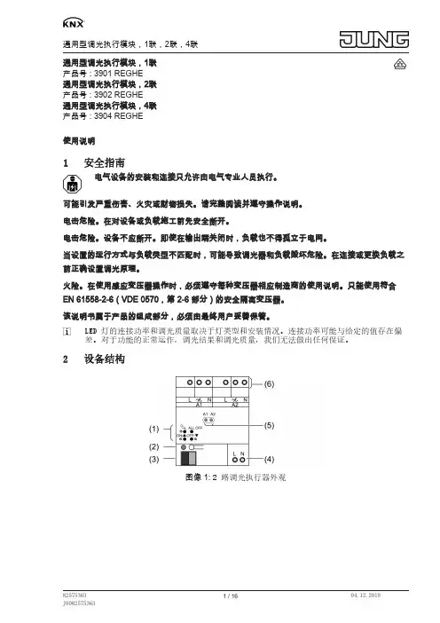
2设备结构图像 1: 2 路调光执行器外观图像 2: 4 路调光执行器外观(1)手动操作键盘(2)编程按键和编程 LED(3)KNX 接口(4)电网接口(选配,如果工作时无总线电压,应该配备)(5)状态 LED(6)输出端接线端子3功能系统信息该设备为 KNX 系统的产品,符合 KNX 标准。
可通过 KNX 培训掌握详细的专业知识。
设备功能会根据软件有所不同。
软件版本、功能范围及软件本身的详细信息请参阅制造商的产品数据库。
借助 KNX 认证软件设计、安装及调试设备。
可以在我们的网页上实时查询最新的产品数据库以及技术说明。
正常应用V04 以上设备版本(参见压印)以及应用程序。
–开关和调光:白炽灯,高压卤素灯,可调光的高压 LED 灯,可调光的节能灯,可调光的电感变压器(带低压卤素灯或低压 LED 灯),可调光的电子变压器(带低压卤素灯或低压 LED 灯)–按照 EN 60715 安装至配电箱中的支承轨道上。

技术手册传感器/开关执行器 1/1 路;2/1 路;2/2 路1/1 路 (SSA-F-1.1.PB.1) 2/1 路 (SSA-F-2.1.PB.1) 2/2 路 (SSA-F-2.2.PB.1)ABB-free@home®目录1手册提示__________________________________________________________________ 3 2安全______________________________________________________________________ 42.1使用的标志 _________________________________________________________________ 42.2按规定使用 _________________________________________________________________ 52.3未按规定使用 _______________________________________________________________ 52.4目标人群/人员资质___________________________________________________________ 52.5安全提示 ___________________________________________________________________ 63环保提示__________________________________________________________________ 7 4产品说明__________________________________________________________________ 84.1供货范围 ___________________________________________________________________ 94.2型号概览 ___________________________________________________________________ 94.3功能概要 ___________________________________________________________________ 94.41/1 路和 2/1 路传感器/开关执行器设备概览_____________________________________ 104.5传感器/开关执行器 2/2 路设备概览 ____________________________________________ 105技术数据_________________________________________________________________ 115.1概览 ______________________________________________________________________ 115.2负载类型 __________________________________________________________________ 115.3规格尺寸 __________________________________________________________________ 125.4接线图 ____________________________________________________________________ 126安装_____________________________________________________________________ 136.1规划提示 __________________________________________________________________ 136.2有关安装的安全提示________________________________________________________ 136.3安装 ______________________________________________________________________ 147调试_____________________________________________________________________ 167.1设备分配和通道设置________________________________________________________ 167.2每个通道的调节方式________________________________________________________ 217.3进行连接 __________________________________________________________________ 248升级方式_________________________________________________________________ 26 9操作_____________________________________________________________________ 27 10保养_____________________________________________________________________ 2810.1清洁 ______________________________________________________________________ 28ABB-free@home®手册提示1手册提示仔细通读本手册并遵守列出的提示。

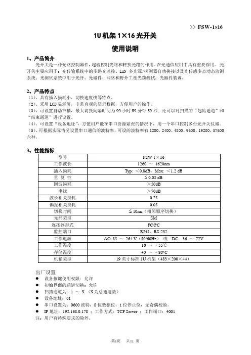
>> FSW-1×161U机架1×16光开关使用说明1、产品简介光开关是一种光路控制器件,起着控制光路和转换光路的作用。
在光通信应用中具有重要作用。
光开关主要应用于:光传输系统中的多路光监控、LAN多光源/探测器自动换接以及光传感多点动态监测系统;光测试系统中用于光纤、光器件、网络和野外工程光缆测试;光器件装调。
2、产品特点(1)、具有插入损耗小,切换速度快等特点。
(2)、采用LCD显示屏,非常直观的显示数据,方便用户的操作。
(3)、可设置自动扫描,最大切换间隔时间为99小时59分钟59秒;还可以对扫描的“起始通道”和“结束通道”进行设置。
(4)、可设置“设备地址”,方便用户能在串口资源紧张的情况下,用一个串口控制多台光开关仪器。
(5)、可根据实际情况设置串口通信的波特率,可设的波特率有1200、2400、4800、9600、19200、57600六种。
3出厂设置●设备按键使用权限:允许●初始界面的通道切换:允许●扫描通道为:1 ~ N (N为总通道数)●设备地址:01●串口设置为:9600波特,8位数据位,1位停止位,无奇偶校验。
●IP地址:192.168.0.178 ;工作方式:TCP Server ;工作端口:4001注:用户有特殊要求的除外。
>> FSW-1×164、使用说明4.1 结构示意说明 4.1.1 面板说明前面板(1)、LCD 显示屏:设备地址、当前通道和相关信息的显示。
(2)、RJ45以太网接口、RS-232(或RS-485)串口:设备监控数据信息的通信接口。
(3)、电源指示灯Power1、Power2:工作电源指示。
(4)、▲——上移键;▼——下移键;Enter ——确定键;Esc ——取消键。
(5)、光接口说明:设备面板上的I/O 口为公共端口,1、2、3、……、16分别为各通道号。
4.2、设备连接说明4.2.1 内部光路连接示意说明1×N 光开关内部光路示意图4.2.2 通信接口连接说明 (1)、RS-232接口设备与计算机连接时,应该使用两端都是孔式DB9的串口交叉线。


KINDUSTRIAL STRENGTH IN-LINE PLASTIC FLOW SWITCHFSW-140 SeriesU P reset Switch Points, 0.07 to 2.00 GPM U ³⁄₈ NPT Male or¹⁄₄" Quick Disconnect U C hemical Resistant PolypropyleneU For Low Viscosity LiquidsThe FSW-140 Series rugged inline flow switches offer superior performance. Their fixed set-point and simple design make it adependable switch. This series is an ideal choice for coolantapplications requiring reliable flow detection in HVAC, semiconductor, welding, medical and otherindustries. The ¹⁄₄" quick disconnect units have a host of snap-on mating adaptors available to fit most piping requirements.SPeCiFiCaTioNSWetted Materials:H ousing: Glass reinforced polypropylene Piston: PPS composite S pring: 316 stainless steel o -Ring: Fluorocarbon operating Pressure:8.6 bar (125 psi) @ 21°C (70°F) 3.4 bar (50 psi) @ 100°C (212°F)operating Temperature: -18 to 100°C (0 to 212°F)Set Point accuracy: 20% of set point Set Point Differential: 20% maximum Switch: SPST , 10VA, normally open at no flowelectrical Termination: 610 mm (24") polymeric leads, 22 AWG Filtration: 100 micronFSW-142 plastic flow switch.FSW-143-QD quickFLOW25(1)¼" Quick Disconnect Male AdaptorSee next page for adaptor model numbers.Both models shown actual size.Comes complete with operator’s manualOrdering Examples: FSW-143, 0.25 GPM, plastic flow switch with 3⁄8 NPT connections.FSW-146-QD, 1.5 GPM plastic flow switch with quick disconnect, two FT-PLC170-04, 1⁄4" ID hose barb/quick disconnect fittings.PiPe THReaD iN LiNe, Streamline Design5⁄8" HexSPeCiFiCaTioNSThermoplastic Quick CouplingsWorking Pressure:Vacuum to 120 psi (8.3 bar)operating Temperature:-40 to 82°C (-40 to 180°F) continuous Materials:Bodies and Valves: Acetalinternal Spring: 316 Stainless Steel external Springs, Pin, Latch: Stainless Steel Seals: Buna, others available Color: Natural white, others available Tubing Sizes: 1⁄4 thru 3⁄8" ID, 1⁄4 and 3⁄8" OD 6 x 4 mm thru 12 x 8 mm (OD x ID)Acetal and chrome-plated brass coupling halves interchange.† Visit /rohs to determine specific RoHS compliance.†† PTF fittings are designed for semi-rigid tubing, i.e. polyethylene, nylon etc. and polyurethane tubing. FT-PLC170-04Both models shown actual size.FT-PLC100-04。

FSW -140 SeriesPlastic Flow SwitchInstallation:All NPT threads should be installed usi ng asuitable thread sealant (Teflon tape or Permatex “No more Leak s”). Sealant must be kept out of unit during installation. FSW -140 Flow S witches Can be Mounted In Various Positions Flow settings are based on a vertical position (inlet port down), using water at +70°F on increasing flow. Slight variation in set point actuation will occur in other mounting orientations.Switch RatingsContact rating: 10WSwitching Current (DC or AC): 0.4 A Max.Carry Current (DC or AC): 0.4 A Max.Break down Voltage: 230 VDC Mi n.M-5172/1112Electrical TerminationNo. 24 AWG, 24” to 26” Polymeric LeadsDimensions - Quick Disconnect PortsDimensions - 3/8” NPT PortsImportant Points:Omega products must be maintainedand installed in strict accordance with the National Electrical Code and the applicable Omega product instructi on Bulletin that cov ers installation, operati on and proper maintenance. Failure to observe this information may result in serious injury or damages.For hazardous area applications involving such things as, but not limited to, ignitable mixtures, combustible dust and flammable materials, use an appropriate explosionproof en-closure or intrinsicall y safe interface device.Please adhere to the pressure and temperature limitations shown throughout this catalog for our level and flow sensors. These limitations must not be exceeded. These pressures and temperatures take into consideration possibl e system surge pressures/ temperatures and thei r frequencies.Selection of materials for compatibility with the media is critical to the life and operation of Omega products. Take care in the proper selection of materials of construction, testing is required.NSF -approvedsensors are made of materials approved for potable water applications according to Standard 61.Stainless steel is generall y regarded as safe by NSF and FDA.Life expectancy of switch contacts varies with application. Ambient temperature changes do affect switch set points, since the gravity of a liquid can vary with temperature.Our sensors have been designed to resist shock and vibra-tion. However, shock and vibrati on shoul d be minimized.Filter liquid media containi ng particulate and/or debris to ensure the proper operation of our products.Electrical entries and mounting points in an enclosed tank may require liquid/vapor sealing.Our sens ors must not be field -repaired.Physical damage sustained by product may render it unser-viceable.240329 rev B。

N A V I G A T I S W I T C H E R O C K E R S W I T C H E S R O T A R Y S W I T C H E S S L I D E S W I T C H E S S N A P A C T I O NS W I T C H E ST A C T I L E S W I T C H E ST O G G L E S W I T C H E S C A P O P T I O N SP U S H B U T T O N S W I T C H E SAudio / Visual Security Devices Industrial ControlsElectrical Housewares Kiosks SpecificationsPart Number ConfiguratorFeatures & BenefitsApplications / Markets• 16mm diameter panel cutout• Single, Bi-color, and RGB LED options • Dot or ring illumination options available• Illuminated ring with laser etched power symbol graphic option• Illuminated ring and power symbol graphic option • Multiple actuator options • Pilot indicator option• IP65 rated, Off-(On), SPST•Soldered wire leads (300mm long) optionalElectrical Rating: 2A, 48VDCMechanical Life: 1,000,000 Cycles Electrical Life: 50,000 CyclesContact Resistance: 50mΩ Max. Insulation Resistance: 1000 MΩ Min. Dielectric Strength: 2,000VACOperating/Storage Temperature: -20°C to 55°C Travel: 1.80mm (Non-Illuminated) 2.20mm (Illuminated) Moisture Protection: IP65Contact Arrangement: SPST Off-(On)Actuation Force: 400 gf Panel Thickness: 1-10mmMounting Nut Torque: 5-14NmF - Flat H - HighActuator Options Medical Equipment2 - Solder W - Wire Terminal Options 4 - Off - (On)*Function OptionsANTI-VANDAL SWITCHES DETECTOR SWITCHES DIP SWITCHESKEYLOCK SWITCHESNAVIGATION SWITCHES ROCKER SWITCHESROTARY SWITCHESSLIDE SWITCHESSNAP ACTION SWITCHESTACTILE SWITCHESTOGGLE SWITCHESCAP OPTIONSPUSHBUTTON SWITCHES ANTI-VANDAL SWITCHESBody DimensionsLED IlluminationBody Dimensions RGB Illumination+12+2-1.50[.059 in]16.50[.650 in]20.0[.787 in]M16 x 1.0THREAD8.50[.335 in].84[.033 in]1.88[.074 in]SHOWN WITH OPTIONAL DOT ILLMINATION9.40[.370 in] 11.80[ .465 in]SHOWN WITH OPTIONALRING ILLUMINATION18.00[.709 in]7.00[.276 in] 3.50[.138 in]2.00[.079 in]20.00[.787 in]16.50[.650 in]1.50[.059 in]M16 x 1.0THREAD9.80[.386 in]3.00[.118 in]ANODE RED LED ANODE GREEN LED ANODE BLUE LEDLED CATHODE ALL 3 COLORS18.00[ .709 in]A N T I -V A N D A L S W I T C H E SD E T E C T O R S W I T C H E SD I P S W I T C HE S K E Y L O C K S W I T C H E SN A V I G A T I O N S W I T C H E S R O C K E R S W I T C H E S R O T A R Y S W I T C H E SS L I D E S W I T C H E SS N A P A C T I O N S W I T C H E S T A C T I L E S W I T C H E S T O G G L E S W I T C H E SC A P O P T I O N SP U S H B U T T O N S W I T C H E SS W I T C H E S Body Dimensions Standard LED Wire Lead** WIRE LEADS PROVIDED ARE DEPENDANT ON THE FUNCTION AND/OR ILLUMINATION SELECTED **WITH GRAPHIC WITHOUT GRAPHIC(4) WIRE, 22 AWG,AWM UL1007 WITH ENDS PRE-STRIPPEDM16x1.0HEATSHRINK OVER SOLDERED CONNECTIONSCABLE TIE25.4[1.0 in]()13.0 2.0.5 .1 in []1.50[.06 in]16.5[.65 in]300.0 10.011.8 .4 in [](+)(-)12SWITCH WIRELENGTH SW1-1WIRE, 22AWG AWM UL1007, WHITE 300.0 [11.8 in]SW1-2WIRE, 22AWG AWM UL1007, GREEN 300.0 [11.8 in]SW1- (+)WIRE, 22AWG AWM UL1007, RED 300.0 [11.8 in]SW1- (-)WIRE, 22AWG AWM UL1007, BLACK300.0 [11.8 in]16.00 -.00.20+.630-.000.008+ in[ ]16.00 -.00.20+.630-.000.008+ in[ ]15.40-.00.10+.606-.000.004+in[]PANEL THICKNESS1-10mm'sRecommended Panel CutoutsANTI-VANDAL SWITCHES DETECTOR SWITCHES DIP SWITCHES KEYLOCK SWITCHESNAVIGATION SWITCHES ROCKER SWITCHESROTARY SWITCHESSLIDE SWITCHES SNAP ACTION SWITCHESTACTILE SWITCHESTOGGLE SWITCHESCAP OPTIONSPUSHBUTTON SWITCHESANTI-VANDAL SWITCHESRecommended Panel CutoutsBody DimensionsStandard RGB Wire LeadBOTTOM VIEWSHOWN WITHOUTWIRING** WIRE LEADS PROVIDED ARE DEPENDANT ON THE FUNCTION AND/OR ILLUMINATION SELECTED **WITH GRAPHIC WITHOUT GRAPHIC(4) WIRE, 22 AWG,AWM UL1007 WITH ENDS PRE-STRIPPEDHEATSHRINK OVER SOLDERED CONNECTIONSM16 X 1.0CABLE TIE13.0 2.0.5 .1 in []1.50[.06 in]25.4[1.0 in]()16.5[.65 in]300.0 10.011.8 .4 in []LEDCATHODE (-)RED LED ANODE (+)BLUE LED ANODE (+)GREEN LED ANODE (+)12SWITCH WIRESW1-1WIRE, 22AWG STRANDED AWM UL1007, WHITE SW1-2WIRE, 22AWG STRANDED AWM UL1007, YELLOW SW1-RED (+)WIRE, 22AWG STRANDED AWM UL1007, RED SW1-GREEN (+)WIRE, 22AWG STRANDED AWM UL1007, GREEN SW1-BLUE (+)WIRE, 22AWG STRANDED AWM UL1007, BLUE SW1- (-)WIRE, 22AWG STRANDED AWM UL1007, BLACK16.00-.00.20+.630-.000.008+ in[]16.00 .20.630 .008 in [ ]15.40-.00.10+.606-.000.004+ in[]PANEL THICKNESS1-10mm'sANTI-VANDAL SWITCHES DETECTOR SWITCHESDIP SWITCHESKEYLOCK SWITCHESNAVIGATION SWITCHESROCKER SWITCHESROTARY SWITCHESSLIDE SWITCHESSNAP ACTION SWITCHESTACTILE SWITCHESTOGGLE SWITCHESCAP OPTIONSPUSHBUTTON SWITCHES ANTI-VANDAL SWITCHESPV6 Series Anti-vandal SwitchRecommended Panel CutoutsHigh ActuatorFlat Actuator Actuator OptionsGraphic OptionsSchematics and Panel CutoutsWITH GRAPHIC WITHOUT GRAPHIC12NON-ILUMINATEDSTANDARD ILLUMINATED+-R G BRGBILLUMINATED-1122 11.90[.469 in]ACTUATOR FLUSH TO TOP OF BEZEL1.50[.059 in]2.90[.114 in]11.90[.469 in]PANEL THICKNESS1-10 mm's16.00 -.00.20+.630-.000.008+ in[ ]LASER ETCHEDILLUMINATEDORIENTATION FLAT FOR GRAPHICILLUMINATEDORIENTATION FLAT FOR GRAPHIC16.00 -.00.20+.630-.000.008+ in[ ]15.40-.00.10+.606-.000.004+ in[]M01 - Illuminated Ring LaserEtched Power Symbol M15 - Illuminated Ring andPower Symbol。
单火线触摸屏遥控调光开关说明书本系列产品依据国际电工惯例,并采用国内外最先进的电子线路设计,电磁兼容性好,性能稳定可靠。
开关面板符合国家:GB16915.1-2003标准;该系列产品荣获国家两项专利:实用新型专利:200920167799.8 外观专利:200930083453.5特别适合家庭、酒店客房、别墅、商场、办公室、医院、仓库等照明场所使用。
一:产品结构示意图及规格说明:1、大小: 88mm*88mm*36mm2、装饰: 常规本白:镀金/镀银/PU银色/PU金色等(颜色装饰任选或自定)。
3、颜色: 面板钢化玻璃为黑色/纯白/银色/粉红(四种任选);底壳为黑色、ABS防火材料。
4、触摸屏:采用最新最先进的电子触控技术,手动触摸。
5、接线柱釆用纯铜。
二:技术指标:1、最大负载电流:总负载≤400W ; 大于400W时可订做。
2、使用寿命:10,0000 次操作;3、工作电压:交流AC:160-250V 50Hz/60H;4、温度环境:-10~60 度; 相对湿度≤90%;(无结露)5、工作电流:AC220V 时,待机功耗<0.2W。
6、遥控距离:空旷距离≥30米(无金属屏蔽情况)7、调节方法:电压调节每级10﹪,共十级或无级调节光式两种。
最低可调到20V左右。
8、安装方法:接线:与普通的传统开关完全一样, 可以直接更换和安装(不需要接零线)。
9、适用灯具:可以适用于市场上常见可调光灯具,常见的白炽灯,射灯,部分LED灯等,(对于节能灯管不适用) ;10:上电系统默认为100﹪最亮。
每级调整10﹪。
三:主要功能:1、多向控制--即可墙上用手动触摸控制,也可移动遥控器控制,手动遥控互动使用更方便;2、集中遥控-- 一个多键的遥控器可集中控制全家的智能遥控开关;3、隔墙遥控-- 可隔墙进行无线远距离遥控(在房间可遥控客厅的灯具);4、来电自熄-- 电网停电后再来电,开关自动处于关闭状态,避免浪费电能;5、互不干扰-- 采用数字编解码技术,无方向性,与邻居家同型号产品间不会互相干扰;6、群控功能-- 可让遥控器上的一个按键同时控制任意多路灯具的同时开、或同时关;7、总开总关-- 遥控器上可自由设定总开/总关按键轻松按下一个按键就能打开或关掉,(己学习并在控制距离范围内的)所有灯具;8、配合我公司的场景遥控器可实现:延时关、娱乐、夜、总开、总关等功能,还可通过电话控制器、防盗报警、网络控制。