双插板阀说明书
- 格式:doc
- 大小:635.50 KB
- 文档页数:3
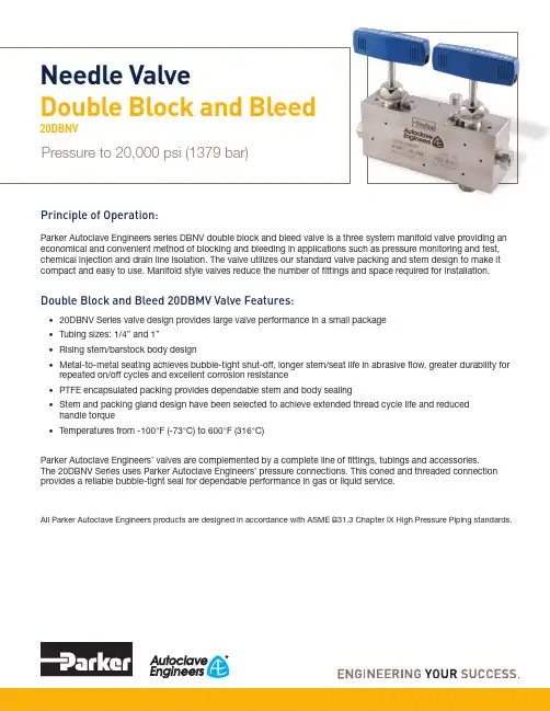
Principle of Operation:Parker Autoclave Engineers series DBNV double block and bleed valve is a three system manifold valve providing an economical and convenient method of blocking and bleeding in applications such as pressure monitoring and test, chemical injection and drain line isolation. The valve utilizes our standard valve packing and stem design to make it compact and easy to use. Manifold style valves reduce the number of fittings and space required for installation.Double Block and Bleed 20DBMV Valve Features:• 20DBNV Series valve design provides large valve performance in a small package • Tubing sizes: 1/4” and 1”• Rising stem/barstock body design• Metal-to-metal seating achieves bubble-tight shut-off, longer stem/seat life in abrasive flow, greater durability for repeated on/off cycles and excellent corrosion resistance• PTFE encapsulated packing provides dependable stem and body sealing• Stem and packing gland design have been selected to achieve extended thread cycle life and reduced handle torque• Temperatures from -100°F (-73°C) to 600°F (316°C)Parker Autoclave Engineers’ valves are complemented by a complete line of fittings, tubings and accessories. The 20DBNV Series uses Parker Autoclave Engineers’ pressure connections. This coned and threaded connection provides a reliable bubble-tight seal for dependable performance in gas or liquid service.All Parker Autoclave Engineers products are designed in accordance with ASME B31.3 Chapter IX High Pressure Piping standards.Needle ValveDouble Block and Bleed20DBNVPressure to 20,000 psi (1379 bar)Double Block & Bleed 20DBNV Series:Pressures to 20,000 psi (1379 bar)TubeOutside DiameterSize (inches)1/43/89/169/16NotesB Standard valve with cryogenic trim materials and PTFE packing to -100°F (-73°C)For additional valve options, contact your Sales Representative.Note: Refer to the Tools, Installation, Operation and Maintenance section for proper maintenance procedures.2Needle Valves: Double Block and Bleed 20DBNV Series 02-9259BE 03183Needle Valves: Double Block and Bleed 20DBNV Series 02-9259BE 0318Ordering Guide:For complete information on available end connections, see end connections options below. 20DBNV valves are urnished complete with tube connections.Connection Options:MAWP: Maximum Allowable Working Pressure4Needle Valves: Double Block and Bleed 20DBNV Series 02-9259BE 0318Material of Construction:Basic Repair Kits for 316 SS Material:Consult your Parker Autoclave Engineers representative for other kit numbers, body part numbers, and pricing. Visit for product Operation manuals.Double Block and Bleed 20DBNV Series Dimensions:G - Packing Gland mounting hole drill size • G1 - Bracket mounting hole size • H* - Dimension is with stem in closed positionPanel mounting drill size: 0.22” all valves • All dimensions for reference only and subject to change • For prompt service, Parker Autoclave stocks select products. Consult factory.For complete information on available options, contact your Sales representative. 20DBNV Series valves are furnished with connection components unless otherwise specified.5Needle Valves: Double Block and Bleed 20DBNV Series 02-9259BE 03186Needle Valves: Double Block and Bleed 20DBNV Series 02-9259BE 0318Electric Valve Actuators :Remotely controlling process flow at high pressure enhances safety and low-ers labor costs. Parker Autoclave Engineers developed a flow control valve available in several models including weatherproof and explosionproof options.The Electrically Actuated Shut-off/Flow Regulating Actuator (FRC Series) is available for most of our Needle Valves through 9/16” tubing size and up to 60,000 psi maximum pressure. They are available in all body patterns except 3-Way / 2-Stem Manifold, and can withstand wide process temperature ranges.Please consult the appropriate needle valve brochure for information on valve options, ratings, flow coefficient, body dimensions, and other specifications.Pneumatic Valve Actuators :The need to control process and vent valves from a remote location makes air operated valves a vital component to many processing operations. All Parker Autoclave Engineers’ valves are available with piston type actuators. Five sizes of air actuators (light, mini-light, medium, heavy duty or extra heavy, single and double stage) are offered to meet the service require-ments of Parker Autoclave Engineers’ Low, Medium and High Pressure needle valves. Both air-to-open (normally closed) and air-to-close (normally open) designs are included in the product line. Optional air to open AND close actuators available upon request. Please see our Pneumatic ValveActuator Brochure to help size the proper actuator for your application.both control and shut-off. While it is not as precise as the control associated with the MicroMetering stem, especially with smaller flows, it does offer substantially better control than the Vee stem.increase service life.7Needle Valves: Double Block and Bleed 20DBNV Series 02-9259BE 0318High/Low Temperature Extension:Not typically needed for 10V/SW Series valves as temperature range does not exceed the barriers below, but option is shown for consideration.-HT High Temperature (over 800°F (427°C))-LTLow Temperature (under -100°F (-73°C))ES Stem Extender:Stem extenders are offered for High and Low temperature operation or to extend through panel or barricade.To order valve with Stem Extender, add “ES-” and length (6”, 12”, 18”, 24”) to beginning of valve part number e.g. ES12-20SM6071. Other lengths to special order.To order Stem Extender only, provide valve model prefix e.g. ES12-20SM6. Handle not included – use same provided with original valve.Needle Valve Clam Shell Handle Lockout:(order separately using part numbers shown below, padlock not included)Clam Shell Handle locks are provided to lockout valves in open or closed position preventing unauthorized personnel from actuating valve during shutdown or emergency situations.This clamshell design is available in four (4) sizes dependent on handle length:P/N AE004855 – 1" to 2.5" handle length P/N 90088 – 2.5" to 5.0" handle length P/N 90194 – 6.5" to 10" handle lengthP/N AE004350 – 8" to 13" handle length! CAUTION !Do not mix or interchange component parts or tubing with those of other manufacturers. Doing so is unsafe and will void warranty.Parker Autoclave Engineers Valves, Fittings, and Tools are not designed to interface with common commercial instrument tubing and are designed to only connect with tubing manufactured toParker Autoclave Engineers AES specifications. Failure to do so is unsafe and will void warranty.Offer of SaleThe items described in this document are available for sale by Parker Hannifin Corporation, its subsidiaries or its authorized distributors. Any sale contract entered by Parker will begoverned by the provisions stated in Parker's standard terms and conditions of sale (copy available upon request).©2018 Parker Hannifin Corporation | Autoclave Engineers is a registered trademark of the Parker Hannifin Corporation Literature #: 02-9259BE March 2018Parker WorldwideAE – UAE, Dubai Tel: +971 4 8875600********************AR – Argentina, Buenos Aires Tel: +54 3327 44 4129******************AT – Austria, Wiener Neustadt Tel: +43 (0)2622 23501-0*************************AT – Eastern Europe, Wiener NeustadtTel: +43 (0)2622 23501 970****************************AU – Australia, Dandenong Tel: +61 (0)3 9768 5555******************************AZ – Azerbaijan, Baku Tel: +994 50 2233 458****************************BE/LX – Belgium, Nivelles Tel: +32 (0)67 280 900*************************BR – Brazil, Sao Jose dos Campos Tel: +55 12 4009 3504******************BY – Belarus, Minsk Tel: +375 17 209 9399*************************CA – Canada, Grimsby, Ontario Tel +1 905-945-2274*********************CH – Switzerland, Etoy Tel: +41 (0) 21 821 02 30*****************************CL – Chile, Santiago Tel: +56 (0) 2 2303 9640******************CN – China, Shanghai Tel: +86 21 2899 5000*****************************CZ – Czech Republic, Klecany Tel: +420 284 083 111*******************************DE – Germany, Kaarst Tel: +49 (0)2131 4016 0*************************DK – Denmark, Ballerup Tel: +45 43 56 04 00*************************ES – Spain, Madrid Tel: +34 902 33 00 01***********************FI – Finland, VantaaTel: +358 (0)20 753 2500*************************FR – France, Contamine s/Arve Tel: +33 (0)4 50 25 80 25************************GR – Greece, Athens Tel: +30 210 933 6450************************HU – Hungary, Budapest Tel: +36 1 220 4155*************************ID – Indonesia, Tangerang Tel: +62 (0)21 7588 1906********************IE – Ireland, DublinTel: +353 (0)1 466 6370*************************IN – India, MumbaiTel: +91 22 6513 7081-85IT – Italy, Corsico (Ml)Tel: +39 02 45 19 21***********************JP – Japan, Tokyo Tel: +(81) 3 6408 3900******************KR – South Korea, Seoul Tel: +82 2 559 0400*******************KZ – Kazakhstan, Almaty Tel: +7 7272 505 800****************************LV – Latvia, Riga Tel: +371 6 745 2601************************MX – Mexico, Toluca Tel: +52 722 275 4200*******************MY – Malaysia, Selangor Tel: +603 784 90 800*******************NL – The Netherlands, Oldenzaal Tel: +31 (0)541 585 000********************NO – Norway, Stavanger Tel: +47 (0)51 826 300************************NZ – New Zealand, Mt Wellington Tel: +64 9 574 1744PL – Poland, Warsaw Tel: +48 (0)22 573 24 00************************PT – Portugal, Leca da Palmeira Tel: +351 22 999 7360**************************RO – Romania, Bucharest Tel: +40 21 252 1382*************************RU – Russia, Moscow Tel: +7 495 645-2156************************SE – Sweden, Spånga Tel: +46 (0)8 59 79 50 00************************SG – Singapore,Tel: +65 6887 6300*******************SK – Slovakia, Banská Bystrica Tel: +421 484 162 252**************************SL – Slovenia, Novo Mesto Tel: +386 7 337 6650**************************TH – Thailand, Bangkok Tel: +66 2 186 7000*********************TR – Turkey, Istanbul Tel: +90 216 4997081************************TW – Taiwan, Taipei Tel: +886 2 2298 8987*************************UA – Ukraine, Kiev Tel: +380 44 494 2731*************************UK – United Kingdom, Warwick Tel: +44 (0)1926 317878********************USA – IPD, Huntsville Tel: +1 256 881 2040*****************USA – Autoclave Engineers, Erie Tel: +1 814 860 5700*******************VN – Vietnam, Hochi Minh City Tel: +84 (0)8337 546 51**********************ZA – South Africa, Kempton Park Tel: +27 (0)11 961 0700*****************************ISO-9001 CertifiedInstrumentation Products Division Autoclave Engineers Operation 8325 Hessinger Drive Erie, PA 16509-4679Tel: 814 860 5700Fax: 814 860 /ipdusInstrumentation Products Division Autoclave Engineers Operation, Houston15340 Vantage Parkway, East Houston, TX 77032Tel: 281 987 3828Fax: 281 987 2318Parker Hannifin Manufacturing Ltd.Instrumentation Products Division, EuropeRiverside RoadPottington Business ParkBarnstaple, UK, EX31 1NP , UK Tel: 44 1271 313131Fax: 44 1271 373636WARNINGFAILURE, IMPROPER SELECTION OR IMPROPER USE OF THE PRODUCTS AND/OR SYSTEMS DESCRIBED HEREIN OR RELATED ITEMS CAN CAUSE DEATH,PERSONAL INJURY AND PROPERTY DAMAGE.This document and other information from Parker Hannifin Corporation, its subsidiaries and authorized distributors provide product and/or system options for further investigation by users having technical expertise. It is important that you analyze all aspects of your application and review the information concerning the product or system in the current product catalog. Due to the variety of operating conditions and applications for these products or systems, the user, through its own analysis and testing, is solely responsible for making the final selection of the products and systems and assuring that all performance, safety and warning requirements of the application are met. The prod-ucts described herein, including without limitation, product features, specifications, designs, availability and pricing, are subject to change by Parker Hannifin Corporation and its subsidiaries at any time without notice.Needle Valves: Double Block and Bleed 20DBNV Series 02-9259BE 0318。
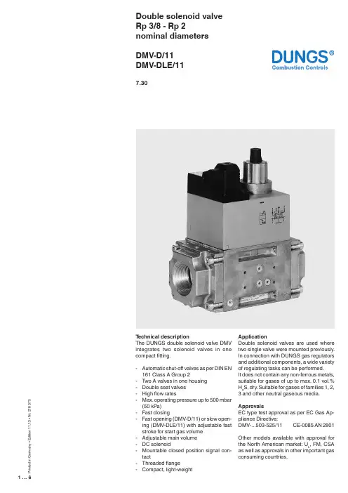
1 (6)P r i n t e d i n G e r m a n y • E d i t i o n 11.13 • N r . 218 375Double solenoid valve Rp 3/8 - Rp 2nominal diameters DMV-D/11DMV-DLE/117.30T echnical descriptionThe DUNGS double solenoid valve DMV integrates two solenoid valves in one compact fitting.- Automatic shut-off valves as per DIN EN 161 Class A Group 2- T wo A valves in one housing - Double seat valves - High flow rates- Max. operating pressure up to 500 mbar (50 kPa)- Fast closing- Fast opening (DMV-D/11) or slow open -ing (DMV-DLE/11) with adjustable fast stroke for start gas volume - Adjustable main volume - DC solenoid- Mountable closed position signal con -tact- Threaded flange- Compact, light-weightApplicationDouble solenoid valves are used where two single valve were mounted previously. In connection with DUNGS gas regulators and additional components, a wide variety of regulating tasks can be performed.It does not contain any non-ferrous metals, suitable for gases of up to max. 0.1 vol.% H 2S, dry. Suitable for gases of families 1, 2, 3 and other neutral gaseous media.ApprovalsEC type test approval as per EC Gas Ap -pliance Directive:DMV-...503-525/11 CE-0085 AN 2801Other models available with approval for the North American market: U L , FM, CSA as well as approvals in other important gasconsuming countries.SpecificationsNominal diameters Flange with pipe thread as per ISO 7-1Max. operating pressure Solenoid valve V1 Solenoid valve V2 Closing timeOpening timeFast strokeMain volume restrictor Materials of gas conveying parts Ambient temperature Installation positionDirt trapMeasuring gas connectionIgnition gas connection Burner pressure monitor p Br Voltage/frequencyRating / power consumption Degree of protection Switch-on duration Electrical connection Radio interference Closed position signal contact DMV 503 DMV 507 DMV 512, 520 DMV 525Rp 3/8,Rp 1/2 Rp 1/2,Rp 3/4,Rp 1 Rp 1,Rp 1 1/4,Rp 1 1/2,Rp 2 Rp 2and their combinations500 mbar (50 kPa)Automatic shut-off valve as per EN 161: Class A, Group 2Automatic shut-off valve as per EN 161: Class A, Group 2< 1 sDMV-D…/11: < 1 sDMV-DLE…/11: approx. 20 s at room temperature +20 °C and without fast stroke AdjustableDMV-D.../11 and DMV-DLE adjustable at V1, DMV-503/11 at V2 Housing: aluminium, steel, no non-ferrous metalsSeals at valve seat: NBR basis, suitable for gases as per G260/l-15 °C to +60 °CSolenoid vertically upright to lying horizontallySieve installed. T o protect the complete gas train we recommend you to install an upstream gas filter (refer to Datasheet 11.02)G 1/8 DIN ISO 228 on both sides upstream of V1, between V1 and V2, down-stream of V2 at input and output flanges.Pressure switch can be mounted to input and output flanges. By mounting a pressure switch, measuring/ignition gas connection can be partly excluded.G 1/2 ignition gas flange as per ISO 228, possible on both sides between V1 and V2 Connection downstream of V2GW...A2 pressure switch can be mounted to the adapter laterally and to the flange50 - 60 Hz, 220 V - 240 V AC, -15 % +10 %, further voltages on requestOther preferred voltages: 50 - 60 Hz, 110 V - 120 V AC, 24 V - 28 V DCat 230 V AC, +20 °C: refer to type overviewIP 54100 %Plug connection as per DIN EN 175301-803, PG* 11 cable gland on request (* = heavy-gauge conduit thread)Degree of interference NType K01/1 (DIN tested), can be mounted to V1 and V2, DMV-503/11 only to V22 (6)c♦ = standard (♦) = on request-- = not possibleFlow losses in (m3/h) air when in-Gas pressure regulator, type FRIThe DMV-507-520/11 double solenoid valve is already prepared for connection with the gas pressure regulator, type FRI.../6 at the factory.The pressure regulator can be installed upstream or downstream of the double solenoid valve depending on the task.FRI.../6 mounting set to DMV.../11Order No. 219 967FRI 705 - 707/6 to DMV 507/11Order No. 219 968FRI 710-712/6 to DMV 512/11-520/11Information on system accessoriesVPS 504 valve proving systemPressure regulator with integrated FRI gas filterPressure limiter ÜB, NB...A2 for multiple actuatorsCompact pressure switch for mul-tiple actuators GW…A5K01/1 closed position signal con-tact to monitor closed position of valvesIf a system accessory isadded, it may not be possibleto mount further devices.5 (6)6 (6)We reserve the right to make any changes in the interest of technical progress.Double solenoid valve Flow diagram Rp 3/8 - Rp 2nominal diameters DMV-D/11DMV-DLE/11Head Offices and FactoryKarl Dungs GmbH & Co. KG Siemensstraße 6-10D-73660 Urbach, Germany T elephone +49 (0)7181-804-0Fax +49 (0)7181-804-166Postal addressKarl Dungs GmbH & Co. KG Postfach 12 29D-73602 Schorndorf, Germany ********************Internet 。

插板闸门浙江永嘉双金自控阀门厂插板闸门一、概述:插板(螺旋)闸门用于建材、冶金、矿山、电力、化工、玻璃、轻工、粮食等行业的库顶、库底及进出口等。
是控制流量变化较大,启动频繁,切断迅速的理想设备。
二、结构特点:结构简单、操作灵活、重量轻、无卡阻、切断快,特别适用于各类无粘度的固体、粉料及小于Φ 10mm 的颗粒料,晶粒料的输送及流量调节,安装不受角度限制,操作方便,能随时调节开度。
该阀门有手轮和链轮操纵两种操作形式, I 型为手轮, II 为链轮。
单向和双向两种结构形式, LZD 为单向、 LZS 为双向。
三、工作原理:主要由框架、闸板、丝杆、螺母等零件构成,用手转动手轮使丝杆带着丝杆螺母和闸板沿水平方向往复运动,达到闸门的启闭目的。
四、主要零件材料及连接尺寸:类A B C×C H L n-d 重量 单2 2296×296 820 100 8-Φ12 62 2 3346×346 930 100 8-Φ14 70.5 3 3396×396 1050 100 8-Φ14 81 4 4496×496 140 100 12-Φ14 114 4 5556×556 1450 120 12-Φ18 130 5 5606×606 1610 120 16-Φ18 147 双6 6706×706 1830 120 16-Φ18 169 77820×820 2130 140 20-Φ18 236五、使用说明:1.本阀可水平安装或垂直安装,安装时两法兰连接中间必须加密封垫片,然后锁紧螺栓。
2.操作时手轮顺时针旋转为阀关,反之为开,不得在手轮上再增加辅助杠杆。
3.若长期存放应使设备处于关闭状态,各传动部位应加润滑油,不允许露天存放或堆置。
4.电动装置可根据客户要求配型,(电压、电流、调节型、开关型、力矩等)。
双层气动插板阀使用说明书
概述
双层气动插板阀是根据蘑菇头式、锥形阀等结构的卸灰阀所存在的“体积大、泄漏率高、阀头易磨损以及卡料、心机易烧毁、在工业生产流程中无法进人自动控制”等缺陷而研制的一种结构简单、设计新颖的更新换代之产品。
可广泛应用于冶金、矿山、建材、电力、化丁等工业生产流程需要远程控制或现场控制卸灰的过程中。
特点
1、使用气缸驱动可实现远距离控制、中央调度室监控和微机控制;
2、通电后,自动完成上、下阀之间互相交替工作,确保正压或负压卸料的工况下不会泄压,至设定的卸料量后自动停止,双阀全部关闭;
3、卸料途中遇到卡料现象时,可自动处理故障;
4、泄漏率低,泄漏率≤0.05%;
5、采用气源作动力源,过载自动卸荷,白锁性好,不漏油,运行平稳;能耗低;
6、采用插板结构卡料现象比其它结构卸灰阀的频率低且不易磨损。
工作原理
本阀为双层气动插板式的卸料装置,接通电源后,上阀气缸自动打开闸板,停留数秒卸料,然后关闭上阀闸板,后转入下阀工作,下阀气缸打开闸板后,停留数秒卸料,然后关闭下阀闸板,转入上阀工作。
如此交替工作,至设定的卸灰量后,自动停止全过程工作。
全程通过PLC自动控制。
上、下阀打开时间,卸灰周期都可以通过触摸屏进行调节。
层气动插板排灰阀选型规格及技术参数
备注:1、用户如需表中未列出的特殊要求,可按用户要求设计制造;。
浙江四通阀门制造有限公司
插板阀使用说明书
一、产品用途:
插板阀是一种粉料、晶粒料、颗粒料及小块物料输送管道,调节或切断物料流量的主要控制设备,广泛地应用于冶金、矿山、建材、化工等行业系统中,控制物料的流量调节或切作用。
二、产品特点:
具有结构简单、操作灵活、重量轻、无卡组、特别适用于各种固体物料、50mm左右、团状物料的输送及流量调节、安装不受角度限制、操作方便、能随时调节开度等优点。
三、产品使用性能:
公称压力:0.05Mpa;介质流量:≤28m/s;工作温度:≤300℃;适用介质:无粘度的粉尘气体、固体粉料、小颗粒物料。
四、安装与使用:
1. 本阀门安装在管道上时,阀杆可以向上,也可以水平.
2.检查各螺纹连接是否有松懈,并调节拧紧;
3.卸掉阀门通道两端闷盖,清洁内腔,去除油垢;
4.剥去阀杆防护油纸后,在阀杆上重新涂润滑脂;
5.冲洗、清洁管路,以免损坏密封面。
4.阀门启闭时,开启电动(气动)执行器通过阀杆升降进行开启和关闭,启闭过程中受力应均匀,到位前应缓速逐渐开启到位或关闭至密封。
五、储备
1.本阀门应存放在干燥通风的室内,做到防潮、防雨、防锈。
2.阀门存放与运输时启闭件应处于关闭位置,
3.通径两端用闷盖塞紧,予以防尘、防锈,保持通道清洁;
4.长久放置时应定期检查。
对阀杆表面、两通道、密封面、两端法兰上的污垢和锈迹进行检查后,重新涂刷防锈油及予以防护。
六、结构图
六、可能发生的故障和消除方法:。
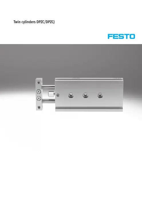
Twin cylinders DPZC/DPZCJTwin cylinders DPZC/DPZCJ Key featuresVariantsDPZC-…-S2DPZCJMounting optionsHorizontal mounting from above Horizontal mounting frombelowSide mounting frombelowStroke precision adjustment•The screw allows adjustment of thestandard strokes within a range of10mm.Flexible cushioningbufferScrew-U-Type discontinuedAvailable up until2010Subject to change–2010/02 2 Internet:/catalogue/...2010/02–Subject to change 3Internet:/catalogue/...Twin cylinders DPZC/DPZCJProduct range overview-U-Type discontinuedAvailable up until 2010Twin cylinders DPZC/DPZCJPeripheralsoverviewAccessoriesBrief description Page/Internet 1Proximity sensorSME/SMT-10Can be integrated in the cylinder profile barrel222One-way flow control valveGRLAFor speed regulation223Push-in fittingQSFor connecting compressed air tubing with standard O.D.to CETOP RP54P quick star–Centring sleeveZBH 6pieces included in scope of delivery22-U-Type discontinuedAvailable up until2010Subject to change–2010/02 4 Internet:/catalogue/...2010/02–Subject to change 5Internet:/catalogue/...Twin cylinders DPZC/DPZCJType codesDPZC—10—40—P—A—GF—S2TypeDouble-acting DPZC Twin cylinder with one yoke plateDPZCJ Twin cylinder with through piston rods and two yoke plates Piston ∅[mm]Stroke [mm]Cushioning PFlexible cushioning rings/plates at both endsPosition sensing A For proximity sensingGuide GF Plain-bearing guideKF Recirculating ball bearing guide Variant S2Through piston rods-U-Type discontinuedAvailable up until 2010Subject to change –2010/026 Internet:/catalogue/...Twin cylinders DPZCTechnical data Function-N-Diameter 6,10,16mm -T-Stroke length 10…100mm-W-VariantsS2DPZC-…DPZC-…-S2General technical data Piston ∅61016Pneumatic connection M3M3M5Operating medium Filtered compressed air,lubricated or unlubricated Operating pressure [bar]GF 2.5…10 1.5…101…10p g p []KF2...10 1.5...101 (10)Constructional design Parallel piston rodsg Parallel piston rods with yokeCushioning Flexible cushioning rings/plates at both ends Position sensing For proximity sensing Type of mounting Via through-holes yp gVia female thread Mounting positionAnyProtection against torsion/guide Parallel piston rods/with plain-bearing or ball bearing guideAmbient conditions VariantPlain-bearing guide GFRecirculating ball bearing guide KF Ambient temperature 1)[°C]–5…+60Corrosion resistance class CRC2)2–ATEXSpecified types 1)Note operating range of proximity sensors2)Corrosion resistance class 2according to Festo standard 940070Components requiring moderate corrosion resistance.Externally visible parts with primarily decorative surface requirements which are in direct contact with a surrounding industrial atmosphere or media such as cooling or lubricating agentsSpeeds [m/s]with maximum stroke length Piston ∅61016Maximum speed 0.5 1.0 1.0Minimum speed0.050.050.05-U-Type discontinuedAvailable up until 20102010/02–Subject to change 7Internet:/catalogue/...Twin cylinders DPZCTechnical dataForces [N]and impact energy [J]Piston ∅61016Theoretical force at 6bar,advancing 3494241Theoretical force at 6bar,retracting 1960181Max.impact energy at the end positions 0.010.080.16v perm.=2x E perm.m dead +m loadᎩm load =2x E perm.v 2−m deadMaximum permissible load:Permissible impact velocity:v perm.Permissible impact velocity E perm.Max.impact energy m dead Moving load (drive)m loadMoving work load-H-NoteThese specifications represent the maximum values which can be re-ached.Note the maximum permitted impact energy.Maximum permissible load m as a function of the impact speed v Plain-bearing guide GFRecirculating ball bearing guideKFm [g ]v[m/s]m [g ]v [m/s]Through piston rod with plain-bearing guide GF Through piston rod with recirculating ball bearing guideKFm [g ]v [m/s]m [g ]v [m/s]-U-Type discontinuedAvailable up until 2010Subject to change –2010/028 Internet:/catalogue/...Twin cylinders DPZCTechnical data Weights Piston ∅6mm Piston ∅10mm Piston ∅16mm Stroke [mm]Piston rods at one end Through piston rods Piston rods at one end Through piston rods Piston rods at one end Through piston rods Product weight [g]1075901201602303202010513016021029041030140170200260350500401702102403204205805020025028037048067080––––670930100––––8001100Moving load [g]10374659821271772039486387135185304150659114319340435272961502005045547610015820880––––182216100––––198224Safety distances Cylinder to cylinderSafety distance X must be main-tained when positioning cylinders together in series,as the stray fields of the switching magnets can result in faulty switching.1Slot 12Slot 2Piston ∅6101661016Min.safety distance X SME-10…162015162416y [mm]SMT-10…59681214-U-Type discontinuedAvailable up until 20102010/02–Subject to change 9Internet:/catalogue/...Twin cylinders DPZCTechnical data Materials Sectional viewTwin cylinder Plain-bearing guide GF Recirculating ball bearing guide KF 1Housing Wrought aluminium alloy Wrought aluminium alloy 2Yoke plate Tool steelTool steel3Plug cap Wrought aluminium alloy Wrought aluminium alloy 4Piston rod High-alloy stainless steel Case-hardened steel–Seals Polyurethane,nitrile rubber Polyurethane,nitrile rubber Note on materialFree of copper,PTFE and siliconeFree of copper,PTFE and siliconeMaximum effective load F [N]Plain-bearing guide GF and recirculating ball bearing guide KFPiston rods at one end Piston ∅XS Stroke [mm][mm][mm]1020304050801006GF0 1.9 1.6 1.35 1.2 1.1––KF 1.9 1.5 1.3 1.10.95––10GF 0 4.5 3.9 3.4 3.0 2.7––KF 5.2 4.3 3.7 3.3 2.9––C t f it f ff ti l d16GF 08.17.1 6.3 5.6 5.1 4.0 3.51Centre of gravity of effective load KF8.57.26.35.65.03.83.3Through piston rodsPiston ∅XS Stroke [mm][mm][mm]1020304050801006GF0 2.7 2.7 2.65 2.65 2.6––KF 2.7 2.6 2.55 2.5 2.5––10GF 0 6.7 6.7 6.7 6.6 6.6––KF 9.29.08.88.78.6––16GF 014.814.714.614.514.414.314.2KF15.615.214.914.714.514.114.0-U-Type discontinuedAvailable up until 2010Twin cylinders DPZCTechnical dataPermissible torque load M[Nm]Plain-bearing guide GF and recirculating ball bearing guide KFPiston rods at one endPiston∅Stroke[mm][mm]1020304050801006GF0.0150.0130.0110.0090.008––KF0.0150.0120.0100.0090.008––10GF0.0450.0390.0340.0300.027––KF0.0520.0430.0370.0320.029––16GF0.1010.0880.0780.0700.0640.0500.043KF0.1060.0900.0790.0700.0630.0480.041Through piston rodsPiston∅Stroke[mm][mm]1020304050801006GF0.0210.0210.0210.0210.021––KF0.0220.0210.0200.0200.020––10GF0.0670.0670.0670.0660.066––KF0.0920.0900.0880.0870.086––16GF0.1850.1830.1820.1810.1810.1780.177KF0.1950.1900.1860.1830.1810.1760.175Torsional backlash pPlain-bearing guide GF and recirculating ball bearing guide KF+ρ–ρPiston∅61016In retracted stateTorsional backlash[°]GF0.070.050.05[]KF0.090.080.06In advanced state with maximum strokeTorsional backlash[°]GF0.400.300.30[]KF0.700.500.50Deflection of piston rod Graphs 11f=f1+f2f=Total deflection of piston rodf1=Deflection due to bearing backlashf2=Deflection due to lateral force-U-Type discontinuedAvailable up until2010Subject to change–2010/02 10 Internet:/catalogue/...Technical dataDeflection f1due to bearing backlash as a function of the stroke l Plain-bearing guide GFRecirculating ball bearing guide KFl [mm]f 1[m m ]f 1[m m ]l [mm]Through piston rod with plain-bearing guide GFThrough piston rod with recirculating ball bearing guide KFl [mm]f 1[m m ]l [mm]f 1[m m ]Deflection f2due to lateral force Fq as a function of the stroke Piston ∅6mmPiston ∅10mmf 2[m m ]Fq [N]Fq [N]f 2[m m ]Piston ∅16mmf 2[m m ]Fq [N]110mm stroke 220mm stroke 330mm stroke 440mm stroke 550mm stroke 680mm stroke 7100mm strokeTechnical dataTechnical data∅B1B2B3B4±0.1B5B6D1∅D2∅H7D3∅H7D4∅D5∅D6∅H7[mm]GF KF63537162818.554h84h6556 3.37 10444620352356h86h6758 4.27 165658254529 5.58h88h6758 4.27∅D7D8EE H1H2H3H4L9L10L11L12±0.1L13±0.1L14±0.1[mm]6M4M3M31614 3.588.5823.51320–10M5M4M31614 3.589.5829222012 16M5M5M52119 5.516101034.5222012∅L15L16±0.1L17T1T2T3T4T5T6T7ß1ß2[mm]6– 6.532 1.30.74 1.3 4.5 3.4 1.6 5.5 5.5 10201236 1.60.54 1.3 5.5 4.5 1.687 16201240 1.60.55 1.36 4.5 1.698∅Stroke L1L2L3L4L51)±0.1L61)±0.1L71)±0.1[mm][mm]BasicversionS2BasicversionS2BasicversionS2BasicversionS2BasicversionS2610738856.571.549.24826.5–40–––20839866.581.559.25836.54040–––309310876.591.569.26846.54040–––4010311886.5101.579.27856.54040–––5011312896.5111.589.28866.54040–80–101081100.563.58355.55427.5–––––2091110.573.59365.56437.5–––––30101120.583.510375.57447.54040–––40111130.593.511385.58457.54040–––50121140.5103.512395.59467.54040–80–161090118.57098.561.56427–––60–20100128.580108.571.574374040–––30110138.590118.581.584474040–80–40120148.5100128.591.594574040–80–50130158.5110138.5101.51046740406080–80160188.5140168.5131.51349740408080–100180208.5160188.5151.5154117404080801201)Tolerance between centring holes±0.02mmTechnical dataTechnical dataFunction-N-Diameter6,10,16mm-T-Stroke length10…100mmGeneral technical dataPiston∅61016Pneumatic connection M3M3M5Operating medium Filtered compressed air,lubricated or unlubricatedp g p[]Operating pressure[bar]GF 2.5...10 1.5...101 (10)KF2...10 1.5...101 (10)gConstructional design Parallel piston rodsParallel piston rods with yokeCushioning Flexible cushioning rings/plates at both endsPosition sensing For proximity sensingyp gType of mounting Via through-holesVia female threadMounting position AnyProtection against torsion/guide Parallel piston rods/with plain-bearing or ball bearing guideAmbient conditionsVariant Plain-bearing guide GF Recirculating ball bearing guide KFAmbient temperature1)[°C]–5…+60Corrosion resistance class CRC2)2–ATEX Specified types 1)Note operating range of proximity sensors2)Corrosion resistance class2according to Festo standard940070Components requiring moderate corrosion resistance.Externally visible parts with primarily decorative surface requirements which are in direct contact with a surrounding industrial atmosphere or media such as cooling or lubricating agentsSpeeds[m/s]with maximum stroke lengthPiston∅61016Maximum speed0.50.80.8Minimum speed0.050.050.05Forces[N]Piston∅610161960181Theoretical force at6bar,advancingand retractingTechnical data Impact energy [J]Piston ∅61016Max.impact energy at the end positions 0.0160.080.16v perm.=2x E perm.m dead +m loadᎩm load =2x E perm.v 2−m deadMaximum permissible load:Permissible impact velocity:v perm.Permissible impact velocity E perm.Max.impact energy m dead Moving load (drive)m loadMoving work load-H-NoteThese specifications represent the maximum values which can be re-ached.Note the maximum permitted impact energy.Maximum permissible load m as a function of the impact speed v Plain-bearing guide GFRecirculating ball bearing guide KFm [g ]v [m/s]m [g ]v [m/s]Weights Stroke Piston ∅6mm Piston ∅10mm Piston ∅16mm[mm]Product weight [g]101302104102017026050030210310580402503606705029041076080––1020100––1200Moving load [g]10871282562091136272309514528840991543045010316332080––367100––398Technical dataSafety distancesCylinder to cylinderSafety distance X must be main-tained when positioning cylinderstogether in series,as the stray fieldsof the switching magnets can resultin faulty switching.1Slot12Slot2Piston∅6101661016 yMin.safety distance X SME-10 (162015162416)[mm]SMT-10 (59681214)MaterialsSectional viewTwin cylinder Plain-bearing guide GF Recirculating ball bearing guide KF1Housing Wrought aluminium alloy Wrought aluminium alloy2Yoke plate Tool steel Tool steel3Plug cap Wrought aluminium alloy Wrought aluminium alloy4Piston rod High-alloy stainless steel Case-hardened steel–Seals Polyurethane,nitrile rubber Polyurethane,nitrile rubberNote on material Free of copper,PTFE and silicone Free of copper,PTFE and siliconeTechnical dataMaximum effective load F[N]Plain-bearing guide GF and recirculating ball bearing guide KFPiston∅XS Stroke[mm][mm][mm]1020304050801006GF0 2.7 2.7 2.65 2.65 2.6––KF 2.7 2.6 2.55 2.5 2.5––10GF0 6.7 6.7 6.7 6.6 6.6––KF9.29.08.88.78.6––16GF014.814.714.614.514.414.314.2 1Centre of gravityof effective load KF15.615.214.914.714.514.114.0Permissible torque load M[Nm]Plain-bearing guide GF and recirculating ball bearing guide KFPiston∅Stroke[mm][mm]1020304050801006GF0.0210.0210.0210.0210.021––KF0.0220.0210.0200.0200.020––10GF0.0670.0670.0670.0660.066––KF0.0920.0900.0880.0870.086––16GF0.1850.1830.1820.1810.1810.1780.177KF0.1950.1900.1860.1830.1810.1760.175Torsional backlash pPlain-bearing guide GF and recirculating ball bearing guide KF+ρ–ρPiston∅61016In retracted state[]Torsional backlash[°]GF0.070.050.05KF0.090.080.06In advanced state with maximum stroke[]Torsional backlash[°]GF0.250.200.20KF0.300.250.20Technical data Deflection of pistonrodf =f1+f2f =Total deflection of piston rodf1=Deflection due to bearing backlash f2=Deflection due to lateral forceDeflection f1due to bearing backlash as a function of the stroke l Plain-bearing guide GFRecirculating ball bearing guide KFl [mm]f 1[m m ]l [mm]f 1[m m ]Deflection f2due to lateral force Fq as a function of the stroke Piston ∅6mmPiston ∅10mmf 2[m m ]Fq [N]Fq [N]f 2[m m ]Piston ∅16mmf 2[m m ]Fq [N]110mm stroke 220mm stroke 330mm stroke 440mm stroke 550mm stroke 680mm stroke 7100mm strokeTechnical data∅Stroke D9L1L2L8L10L18L19ß3ß4[mm][mm]6108871.518.5209881.528.53010891.538.540118101.548.550128111.558.51010M8x1100.58319.5815371020110.59329.530120.510339.540130.511349.550140.512359.51610118.598.52020128.5108.53030138.5118.54040M10x1148.5128.5501022101350158.5138.5603380188.5168.590100208.5188.51102010/02–Subject to change 21Internet:/catalogue/...Twin cylinders DPZCJTechnical data-U-Type discontinuedAvailable up until 2010Subject to change –2010/0222 Internet:/catalogue/...Twin cylinders DPZC/DPZCJAccessories1)Packaging unit quantity-U-Type discontinuedAvailable up until 2010。
177908-1177914-1177915-1179463-1179465-1 177915-1179595-1179595-1177917-1177906-6The power double lock connectors are available in wire-to-wire (including free-hanging and panel mount) and wire-to-board configurations. This connector system consists of plug and cap housings for wire termination, optional double lock plates, crimp contacts and PC board pin headers, and is available in a contact centerline spacing of 3.96 mm for wire-to-wire and centerline spacing of 3.96 mm, 6.5 mm, and 13.00 mm for wire-to-board. The power double lock connector system accepts 26-16 AWG wire with insulation diameters up to 3.1 mm and is rated up to 14 Amps per line.POWER DOUBLE LOCK (PDL) CONNECTORSQuick Reference GuideFEATURES & BENEFITS• Discrete wire interconnect available in 1-12 position wire-to-board and wire-to-wire• Multiple colors available for ease of connector identification during assembly and maintenance • Audible click when contact is fully inserted into the housing• Polarizing ribs on plug housing allows for proper mating • Board-mounted headers are compatible with resin or conformal coatings — No drain holes•Solder tail kink along with the polarization peg (boss) feature, secures the header on the board during the solder process• UL recognized, CSA certified, and VDE approved •TPA and GWT availablePRODUCT APPLICATIONS• Household appliances • Gaming • Vending• Garage door openers • Security systems • Industrial controls • HVAC system controls • Fan modules • Business equipment •Small UAVCONTACTS * Part Number suffix -2 represents high contact pressure typePLUG HOUSINGS**2.Available in Type II lock, see catalog 82181 for details.3. Available in Type B lock, see catalog 82181 for details.4.Color Key Code: -1 Natural, -2 Red, -4 Yellow, -6 Blue, -9 Black**GWT version products are also available, please contact our sales representatives for more informationQuick Reference GuideThe PDL contacts are phosphor bronze with pre-tin plating and designed without lances to prevent entanglement of contacts with one another. The receptacle contact gets loaded into the plug housings and the tab contact gets loaded into cap housings.The semi-inner locking system of the PDL design helps eliminate unmating by external force and the audible click helps indicate the connector system is fully latched. The smooth compact design prevents snagging when mated.CAP HOUSINGS**HEADERS**GWT version products are also available, please contact our sales representatives for more informationQuick Reference GuideA double lock plate is available for both plug and cap housings to ensure positive loading and to help prevent contact back-out.The PDL headers offer a kink in the solder tail along with the kink in the mounting boss which secures the header on theboard firmly while soldering. Board mounted headers are compatible with resin or conformal coatings (no drain holes).Positive mounting achieved with Double Lock Mechanism:1. Contact is partially-mounted.2. Double Lock Plate is set.3. Contact is fully pushed in asDouble Lock Plate is pressed.TE Connectivity, TE Connectivity (logo) and Every Connection Counts are trademarks. All other logos, products and/or company names referred to herein might be trademarks of their respective owners.The information given herein, including drawings, illustrations and schematics which are intended for illustration purposes only, is believed to be reliable. However, TEConnectivity makes no warranties as to its accuracy or completeness and disclaims any liability in connection with its use. TE Connectivity‘s obligations shall only be as set forth in TE Connectivity‘s Standard T erms and Conditions of Sale for this product and in no case will TE Connectivity be liable for any incidental, indirect or consequential damages arising out of the sale, resale, use or misuse of the product. Users of TE Connectivity products should make their own evaluation to determine the suitability of each such product for the specific application.© 2016 TE Connectivity Ltd. family of companies All Rights Reserved.1773458-5 APP 08/16 OriginalQuick Reference GuideDESIGN-IN QUESTIONS1.What are the current and voltage requirements for your application?The power double lock connector system has a maximum current rating of 14 Amps per line (based on initial t-rise vs. current testing using 16 AWG in a 2 position connector) and is rated for 300 Volts AC/DC wire-to-wire and 50 Volts AC/DC wire-to-board.2.What are the wire type and size requirements?The power double lock connector system is approved for use with 26-16 AWG wire with an insulation range between 1.3 mm and 3.1 mm.3.What are the number of positions and available space?The power double lock connector system is available in select positions (1-12) on four contact centerline spacings; 3.96 mm, 6.5 mm, 7.92 mm and 13.0 mm. Theoverall mated length of the free-hanging system is 38.7 mm and the maximum height of the wire-to-board system is 25.5 mm.4. What are the operating temperature requirements?The power double lock connector system has a maximum operating temperature of 105°C. For more information regarding operating temperatures refer to Product Specification 108-5410.5.Is contact back-out a concern?Do you need confirmation that the contacts are seated? The power double lock connector system offers an optional double lock plate. The purpose of the double lock plate is two-fold: 1) allows contacts to be fully seated in the housing and 2) it helps prevent the possibility of contact disengagement when wires are exposed to external pressure.TE Connectivity T echnical Support CenterUSA: +1 (800) 522-6752Canada: +1 (905) 475-6222Mexico: +52 (0) 55-1106-0800Latin/S. America +54 (0) 11-4733-2200Germany: +49 (0) 6251-133-1999UK: +44 (0) 800-267666France: +33 (0) 1-3420-8686Netherlands: +31 (0) 73-6246-999China:+86 (0) 400-820-60156.Do you need to differentiate this connector from other connectors in the application?The power double lock connector system offers multiple options of colored housings for ease of connector identification during manufacturing and assembly.7.What is the benefit of choosing a header with a polarization peg (boss)?The power double lock connector system offers headers with or withoutpolarization pegs. The purpose of this feature is to polarize the headers to the PCB so the header can not be placed on the PCB in the wrong orientation. For more information regarding PCB layout please refer to the header product drawing.8.What is the benefit of choosing a high force contact?The power double lock connector system offers high force contacts for use in applications where vibration is prominent. It is important to note that the high force contacts increase the amount of mating force. Refer to Product Specification 108-5410 for more information.9.What is the benefit of choosing Lock Type II or Lock Type B (non-standard) latch?• Lock Type II is offered on the 3.96 mm plugs allowing for easier unmating (more finger room to depress the latch).•Lock Type B is offered on the 6.5 mm plugs providing a slightly lower profile and can be used when the application will not have to be unmated often.177915-2177908-1177914-1177915-1179463-1179465-1 177915-1179595-1179595-1177917-1177906-6。
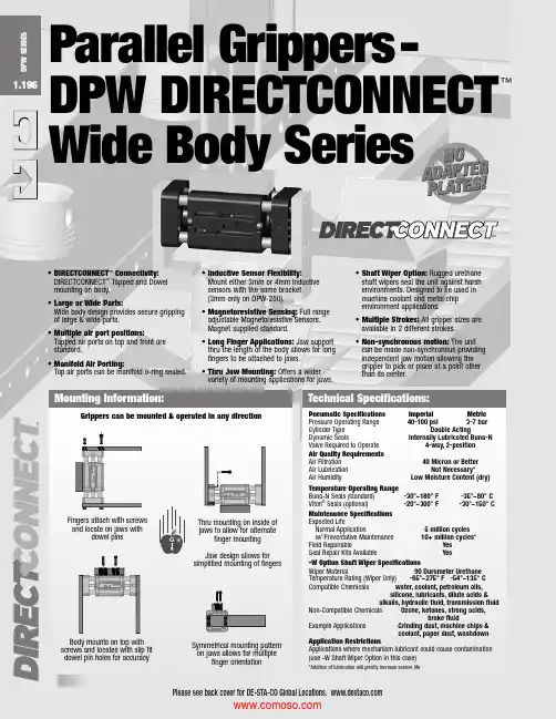
Pneumatic Specifications Imperial Metric Pressure Operating Range 40-100 psi 3-7 bar Cylinder Type Double ActingDynamic Seals Internally Lubricated Buna-N Valve Required to Operate 4-way, 2-position Air Quality RequirementsAir Filtration 40 Micron or Better Air Lubrication Not Necessary *Air Humidity Low Moisture Content (dry)Temperature Operating RangeBuna-N Seals (standard) -30°~180° F -35°~80° C Viton ®Seals (optional) -20°~300° F -30°~150° C Maintenance Specifications Expected LifeNormal Application 5 million cycles w/ Preventative Maintenance 10+ million cycles *Field Repairable Yes Seal Repair Kits Available Yes -W Option Shaft Wiper SpecificationsWiper Material 90 Durometer Urethane Temperature Rating (Wiper Only) -65°~275° F -54°~135° C Compatible Chemicals water, coolant, petroleum oils, silicone, lubricants, dilute acids & alkalis, hydraulic fluid, transmission fluid Non-Compatible Chemicals Ozone, ketones, strong acids, brake fluidExample Applications Grinding dust, machine chips & coolant, paper dust, washdown Application RestrictionsApplications where mechanism lubricant could cause contamination (use -W Shaft Wiper Option in this case)*Addition of lubrication will greatly increase service lifeTechnical Specifications:Grippers can be mounted & operated in any directionFingers attach with screws and locate on jaws withdowel pinsMounting Information:Parallel Grippers-DPW DIRECTCONNECT ™Wide Body SeriesG• DIRECTCONNECT ™Connectivity:DIRECTCONNECT ™Tapped and Dowel mounting on body.• Large or Wide Parts:Wide body design provides secure gripping of large & wide parts.•Multiple air port positions:Tapped air ports on top and front are standard.• Manifold Air Porting:Top air ports can be manifold o-ring sealed.• Inductive Sensor Flexibility:Mount either 3mm or 4mm Inductive sensors with the same bracket (3mm only on DPW-250).• M agnetoresistive Sensing:Full range adjustable Magnetoresistive Sensors. Magnet supplied standard.• Long Finger Applications:Jaw support thru the length of the body allows for long fingers to be attached to jaws.• Thru Jaw Mounting:Offers a wider variety of mounting applications for jaws.• Shaft Wiper Option:Rugged urethane shaft wipers seal the unit against harsh environments. Designed to be used in machine coolant and metal chip environment applications.• Multiple Strokes: All gripper sizes are available in 2 different strokes.• Non-synchronous motion: The unit can be made non-synchronous providing independent jaw motion allowing the gripper to pick or place at a point other than its center.Thru mounting on inside of jaws to allow for alternatefinger mounting Jaw design allows for simplified mounting of fingersBody mounts on top with screws and locates with slip fit dowel pin holes for accuracySymmetrical mounting pattern on jaws allows for multiplefinger orientation1.196D P W SE R I E STM1.197D P W SE R I E SSealed Design (-W option)Urethane shaft wipers prevent against dirty environments (machining chips & coolant, grinding dust, paper millenvironments, etc.)Thru-Jaw MountingC’bores on inside of jaws for thru mounting to increase range ofapplicationsSensorMounting SlotsStandard mounting slots for magneto resistive and inductive sensors (sensors sold separately)Square-Faced JawsAllow for a symmetrical, multi-positional mounting pattern for simplified finger design and increased range of applicationsMultiple Air Port Locations2 standard airport location(front & top)Quality ComponentsHardened precision stainless steel shafting for wear resistance andlong lifeSuperior Jaw SupportEach jaw is supported by 2 shafts that extend the entire length of the body and are guided by 2 oil impregnated bronze bushings pershaftMagneto ResistiveSensorsAn alternative option to inductive sensors (magnets supplied standard)Dowel HolesSlip fit dowel pin holes in body and jawsSimplified Finger MountingLarge jaw configuration allows for simplified finger mountingOptional Non-SynchronousOperation• Two shafts, one with a rack cut into it, are securely fastened to each of the jaws and ARE supported through the length of the body.• Two double acting opposed pistons provide power to the jaws.• The rack shafts of each jaw slide in opposite directions of one another and are synchronized by a piston gear.• This gripper is suitable for internal or external gripping and can be mounted in any orientation.Pressure ExhaustOpen PositionProduct FeaturesOperating PrincipleU.S Patent #5,163,729 Designed, manufactured and assembled in the USAPressureExhaust End PlateJawBodyUrethane Shaft Wipers(-W Option)PistonBearingPinion Gear and Radial BearingRack ShaftClosed PositionMounting PatternsDIRECTCONNECT ™Tapped & Dowel mounting surfaceon top of bodyEnd of Stroke CushionsReduce shock of fully open and close strokesHigh TemperatureOptional Viton ®seals are available for high temperature applicationsSee Page1.198Style -DPW Parallel GripperSize -250M-1 250M-1Stroke: 0.75 in. 19.1 mmGrip Force: 50 lbs. 222 NWeight: 0.662 lbs. 0.30 KgSee Page1.200Style -DPW Parallel GripperSize -250M-2Style: 250M-2Stroke: 1.25 in. 31.8 mmGrip Force: 50 lbs. 222 NWeight: 0.856 lbs. 0.39 KgSee Page1.202Style -DPW Parallel GripperSize -375M-1Style: 375M-1Stroke: 1.00 in. 25.4 mmGrip Force: 100 lbs. 445 NWeight: 1.80 lbs. 0.81 KgSee Page1.204Style -DPW Parallel GripperSize -375M-2Style: 375M-2Stroke: 2.00 in. 50.8 mmGrip Force: 100 lbs. 445 NWeight: 2.66 lbs. 1.20 KgSee Page1.206Style -DPW Parallel GripperSize -500M-1Style: 500M-1Stroke: 1.50 in. 38.1 mmGrip Force: 180 lbs. 800 NWeight: 3.27 lbs. 1.48 KgStyle -DPW Parallel GripperSize -500M-2Style: 500M-2Stroke: 2.50 in. 63.5 mmGrip Force: 180 lbs. 800 NWeight: 4.39 lbs. 2.0 KgShown with -W Shaft Wiper OptionShown with -W Shaft Wiper OptionShown with -W Shaft Wiper OptionShown with -W Shaft Wiper OptionShown with -W Shaft Wiper OptionShown with -W Shaft Wiper OptionPiston ShaftShaftMagnetManifold Air PortsTop air ports can be O-Ring manifold sealed to eliminateair linesCombined 3mm and 4mm Inductive SensorMountingAllows for either 3 or 4mmInductive sensors (3mm only on DPW-250)See Page1.2081.198.3759.5[M3 X 5 DP.][[M3 X 5 DP.](CLOSE PORT)10.52X .166 4.2SENSOR ENTRANCE SLOT 7.92X .227 5.82X .246C L[M4 X 8DP.][4 H7 X 5DP.]37.6PARALLEL GRIPPERS DPW-250M-1DIRECTCONNECT WIDE BODY SERIESNOTE: DIRECTCONNECT DIMENSIONS ARE SHOWN IN BLUE1.199D P W SE R I E SPARALLEL GRIPPERS DPW-250M-1DIRECT CONNECT WIDE BODY SERIESSpecifications Total Rated Grip Force F @ 100 psi, 7 bar............. 50 lbs. 222 N Stroke...................................................................... 0.75 in. 19.1 mm Pressure Range....................................................... 40-100 psi 3-7 bar Cylinder Bore Ø....................................................... 0.625 in. 15.9 mm Displacement.......................................................... 0.023 in 3. 3.8 cm 3Weight..................................................................... 0.662 lbs. 0.30 Kg Temperature Range: Standard Seals...................... -30°~180° F -35°~80° C Viton ® Seals........................... -20°~300° F -30°~150° C Actuation ................................................................ 0.12 sec. 0.12 sec.Accuracy................................................................. ±0.003 in. ±0.08 mm Repeatability............................................................ ±0.001 in. ±0.03 mm Valve required to actuate........................................ 4-way, 2-positionMaximum Tensile T 60 lbs. [267 N ] 12 lbs. [53 N] Maximum Compressive C 60 lbs. [267 N] 12 lbs. [53 N]Maximum Moment M x 120 in.-lbs. [14 Nm] 24 in.-lbs. [3 Nm]Maximum Moment M y 180 in.-lbs.[20 Nm] 36 in.-lbs.[4 Nm]Maximum Moment M z 120 in.-lbs.[14 Nm] 24 in.-lbs.[3 Nm]Capacities are per set of jaws and are not simultaneous111896745220N EFFECTIVE FINGER LENGTH - LF I NG E R F O R C E - F /2255075102127 mmGRIP FORCE PER FINGER1.200.3759.5[(CLOSE PORT)16.9(JAW)2X .166 4.2 SENSOR ENTRANCE SLOT7.92X .2897.3.24 6C L[M4 X 8DP.][37.6PARALLEL GRIPPERS DPW-250M-2DIRECTCONNECT WIDE BODY SERIESNOTE: DIRECTCONNECT DIMENSIONS ARE SHOWN IN BLUE1.201D P W SE R I E SPARALLEL GRIPPERS DPW-250M-2DIRECT CONNECT WIDE BODY SERIESTotal Rated Grip Force F @ 100 psi, 7 bar............. 50 lbs. 222 N Stroke...................................................................... 1.25 in. 31.8 mm Pressure Range....................................................... 40-100 psi 3-7 bar Cylinder Bore Ø....................................................... 0.625 in. 15.9 mm Displacement.......................................................... 0.383 in 3. 6.3 cm 3Weight..................................................................... 0.856 lbs. 0.39 Kg Temperature Range: Standard Seals...................... -30°~180° F -35°~80° C Viton ® Seals........................... -20°~300° F -30°~150° C Actuation ................................................................ 0.14 sec. 0.14 sec.Accuracy................................................................. ±0.003 in. ±0.08 mm Repeatability............................................................ ±0.001 in. ±0.03 mm Valve required to actuate........................................ 4-way, 2-positionMaximum Tensile T 60 lbs. [267 N ] 12 lbs. [53 N] Maximum Compressive C 60 lbs. [267 N] 12 lbs. [53 N]Maximum Moment M x 120 in.-lbs. [14 Nm] 24 in.-lbs. [3 Nm]Maximum Moment M y 180 in.-lbs.[20 Nm] 36 in.-lbs.[4 Nm]Maximum Moment M z 120 in.-lbs.[14 Nm] 24 in.-lbs.[3 Nm]Capacities are per set of jaws and are not simultaneous111896745220N F I N G E R F O R C E - F /2255075102127 mmGRIP FORCE PER FINGER1.20219.1[M5 X 7 DP.][5 H7 X 5 [M5 X 7 DP.](CLOSE PORT)13.04X .166 4.2 SENSOR ENTRANCE SLOT17.82X .262 6.7[M3 X 4 DP.].18 5C L[54.0PARALLEL GRIPPERS DPW-375M-1DIRECTCONNECT WIDE BODY SERIESNOTE: DIRECTCONNECT DIMENSIONS ARE SHOWN IN BLUE1.203D P W SE R I E SPARALLEL GRIPPERS DPW-375M-1DIRECT CONNECT WIDE BODY SERIESSpecifications Total Rated Grip Force F @ 100 psi, 7 bar............. 100 lbs. 445 N Stroke...................................................................... 1.00 in. 25.4 mm Pressure Range....................................................... 40-100 psi 3-7 bar Cylinder Bore Ø....................................................... 0.938 in. 23.8 mm Displacement.......................................................... 0.690 in 3. 11.3 cm 3Weight..................................................................... 1.80 lbs. 0.81 Kg Temperature Range: Standard Seals...................... -30°~180° F -35°~80° C Viton ® Seals........................... -20°~300° F -30°~150° C Actuation ................................................................ 0.16 sec. 0.16 sec.Accuracy................................................................. ±0.003 in. ±0.08 mm Repeatability............................................................ ±0.001 in. ±0.03 mm Valve required to actuate........................................ 4-way, 2-positionMaximum Tensile T 120 lbs. [534 N ] 24 lbs. [107 N] Maximum Compressive C 120 lbs. [534 N] 24 lbs. [107 N]Maximum Moment M x 210 in.-lbs.[24 Nm] 42 in.-lbs.[5 Nm]Maximum Moment M y 300 in.-lbs.[34 Nm] 60 in.-lbs.[7 Nm]Maximum Moment M z 210 in.-lbs.[24 Nm] 42 in.-lbs.[5 Nm]Capacities are per set of jaws and are not simultaneous223 178 134 89 45 0lbs.N F I N G E R F O R C E - F /2 GRIP FORCE PER FINGER 02550178 mmWARNING!102 127153761.20419.1[(CLOSE PORT)4X .166 4.2SENSORENTRANCESLOT2X .46211.7.18 5C L5 H7 X 5 DP.]54.0 PARALLEL GRIPPERS DPW-375M-2DIRECTCONNECT WIDE BODY SERIESNOTE: DIRECTCONNECT DIMENSIONS ARE SHOWN IN BLUE1.205D P W SE R I E SSpecifications Total Rated Grip Force F @ 100 psi, 7 bar............. 100 lbs. 445 N Stroke...................................................................... 2.00 in. 50.8mm Pressure Range....................................................... 40-100 psi 3-7 bar Cylinder Bore Ø....................................................... 0.938 in. 23.8 mm Displacement.......................................................... 1.382 in 3. 22.6 cm 3Weight..................................................................... 2.66 lbs. 1.20 Kg Temperature Range: Standard Seals...................... -30°~180° F -35°~80° C Viton ® Seals........................... -20°~300° F -30°~150° C Actuation ................................................................ 0.20 sec. 0.20 sec.Accuracy................................................................. ±0.003 in. ±0.08 mm Repeatability............................................................ ±0.001 in. ±0.03 mm Valve required to actuate........................................ 4-way, 2-positionPARALLEL GRIPPERS DPW-375M-2DIRECT CONNECT WIDE BODY SERIESMaximum Tensile T 120 lbs. [534 N ] 24 lbs. [107 N] Maximum Compressive C 120 lbs. [534 N] 24 lbs. [107 N]Maximum Moment M x 210 in.-lbs.[24 Nm] 42 in.-lbs.[5 Nm]Maximum Moment M y 300 in.-lbs.[34 Nm] 60 in.-lbs.[7 Nm]Maximum Moment M z 210 in.-lbs.[24 Nm] 42 in.-lbs.[5 Nm]Capacities are per set of jaws and are not simultaneous223 178 134 89 45 0lbs.N F I N G E R F O R C E - F /2 GRIP FORCE PER FINGER 02550178 mmWARNING!102 127153761.206[5 H7 X 5 [M5 X 5 DP.](CLOSE PORT)19.119.24X .166 4.2 SENSOR SLOT18.8.47512.1(OPEN PORT).20 5C L[M6 X 13 DP.][6 H7 X8 DP.]51.00PARALLEL GRIPPERS DPW-500M-1DIRECTCONNECT WIDE BODY SERIESNOTE: DIRECTCONNECT DIMENSIONS ARE SHOWN IN BLUE1.207D P W SE R I E SPARALLEL GRIPPERS DPW-500M-1DIRECT CONNECT WIDE BODY SERIESMaximum Tensile T 600 lbs. [2668 N ] 60 lbs. [267 N] Maximum Compressive C 600 lbs. [2668 N] 60 lbs. [267 N]Maximum Moment M x 600 in.-lbs.[68 Nm] 60 in.-lbs.[7 Nm]Maximum Moment M y 900 in.-lbs.[102 Nm] 90 in.-lbs.[10 Nm]Maximum Moment M z 600 in.-lbs.[68 Nm] 60 in.-lbs.[7 Nm]Capacities are per set of jaws and are not simultaneousSpecifications Total Rated Grip Force F @ 100 psi, 7 bar............. 180 lbs. 800 N Stroke...................................................................... 1.50 in. 38.1 mm Pressure Range....................................................... 40-100 psi 3-7 bar Cylinder Bore Ø....................................................... 1.250 in. 31.8 mm Displacement.......................................................... 1.841 in 3. 30.2 cm 3Weight..................................................................... 3.27 lbs. 1.48 Kg Temperature Range: Standard Seals...................... -30°~180° F -35°~80° C Viton ® Seals........................... -20°~300° F -30°~150° C Actuation ................................................................ 0.20 sec. 0.20 sec.Accuracy................................................................. ±0.003 in. ±0.08 mm Repeatability............................................................ ±0.001 in. ±0.03 mm Valve required to actuate........................................ 4-way, 2-position40035631226722317813489450lbs.NF I NG E R F O R C E - F /2GRIP FORCE PER FINGER517676102127330mm2032292542793051521781.208(CLOSE PORT)19.131.918.8(OPEN PORT)C L[M6 X 13 DP.][ 6 H7 X 8 DP.]51.00PARALLEL GRIPPERS DPW-500M-2DIRECTCONNECT WIDE BODY SERIESNOTE: DIRECTCONNECT DIMENSIONS ARE SHOWN IN BLUE1.209D P W SE R I E SPARALLEL GRIPPERS DPW-500M-2DIRECT CONNECT WIDE BODY SERIESMaximum Tensile T 600 lbs. [2668 N ] 60 lbs. [267 N] Maximum Compressive C 600 lbs. [2668 N] 60 lbs. [267 N]Maximum Moment M x 600 in.-lbs.[68 Nm] 60 in.-lbs.[7 Nm]Maximum Moment M y 900 in.-lbs.[102 Nm] 90 in.-lbs.[10 Nm]Maximum Moment M z 600 in.-lbs.[68 Nm] 60 in.-lbs.[7 Nm]Capacities are per set of jaws and are not simultaneousTotal Rated Grip Force F @ 100 psi, 7 bar............. 180 lbs. 800 N Stroke...................................................................... 2.50 in. 63.5 mm Pressure Range....................................................... 40-100 psi 3-7 bar Cylinder Bore Ø....................................................... 1.250 in. 31.8 mm Displacement.......................................................... 3.068 in 3. 50.3 cm 3Weight..................................................................... 4.39 lbs. 2.0 Kg Temperature Range: Standard Seals...................... -30°~180° F -35°~80° C Viton ® Seals........................... -20°~300° F -30°~150° C Actuation ................................................................ 0.28 sec. 0.28 sec.Accuracy................................................................. ±0.003 in. ±0.08 mm Repeatability............................................................ ±0.001 in. ±0.03 mm Valve required to actuate........................................ 4-way, 2-position40035631226722317813489450lbs.NF I NG E R F O R C E - F /2GRIP FORCE PER FINGER517676102127330mm2032292542793051521781.210DPW SERIES EXPLODED VIEWItem Qty Name01 1 Body02 8 Bushing, Oil Impregnated Bronze 03 2 End Cap 04 2 Jaw05*2 Guide Shaft, Rack06* 2 Guide Shaft (Qty 4 for -NS)07 2Piston Rod 08 2 Piston 09 1 Cap, Gear 10* 1 Gear11* 1 Bearing, Radial12* 2 Piston Rod Wiper (Shaft Wiper"-W" option only)13* 8 Shaft Wiper (Shaft Wiper "-W" option only)14 2 Piston Bumper 15 2 Piston O-ring 16 2 Teflon Ring 17* 2 Body O-ring 18 2 U-cup19 2 Jaw Bumper 20 1 Gear Cap O-ring 21 1 Retaining Ring 22 1 Magnet23 8 End Cap Mntg Screw 24 4 Guide Shaft Mntg Screw 25 4 Piston Shaft Mntg Screw 26* 2 Guide Shaft Alignment Dowel 27 2 Manifold Port Plug28 8 Retainer Ring (Shaft Wiper "-W" Option only)29 2 Retainer Ring (Shaft Wiper "-W" Option only)30* 4 End Cap Mntg Screw 31 4 End Cap Dowel Pins*Notes:1) Contact the Robohand Sales Department for a complete spare parts list with order numbers and prices.2) Q uantity of #6 is 4 when ordering a Non-synchronous gripper.3)Items #5, #10, #11, and #26 are for synchronous grippers only.4) Items #12 and #13 are for –W option only.5) Item #17 (Body O-ring) shown in body groove.6) Item #23 Quantity is 6 for 375-1 and 375-2 only.7) Item #30 is only used in 375-1 and 375-2.Assembly Procedure:1) Lubricate and install seals on piston.2) Install pistons and shafts.3) Mount end caps to enclose piston assembly.4) Install tooling plates and shafts.5) Place bearing, shaft, and gear into body and install cap and retaining ring for sync version.a) For disassembly, use magnet to pull gear out of body.b) Install 2 gear shafts with teeth facing syncing gear. Use dowel to align gear shafts in correct position.-W Option Assembly Procedure:1) Take out guide shaft and piston rod mounting screws.2) Remove jaws from guide shafts and piston rods.3) Take out end cap mounting screws and pull off end caps. Take out piston.4) Slide out shafts and press wipers in pockets thru front side. Install retaining rings.5) Replace shafts, pistons, and end caps.6) Be sure to apply thread locker to mounting screws. The gripper now has shaft wipers.1.211D P W SE R I E S M A I N T E N A N C EDPW SERIES ASSEMBLED VIEWAccessory Installation & Adjustment InstructionsItem Qty Name01 1 Body02 8 Bushing, Oil Impregnated Bronze 03 2 End Cap 04 2Jaw05* 2 Guide Shaft, Rack06* 2 Guide Shaft (Qty 4 for NS)07 2 Piston Rod 08 2 Piston 09 1 Cap, Gear 10* 1 Gear11* 1 Bearing, Radial12* 2 Piston Rod Wiper (Shaft Wiper“-W” option only)13* 8 Shaft Wiper (Shaft Wiper "-W" option only)14 2 Piston Bumper 15 2 Piston O-Ring 16 2 Teflon Ring 17* 2 Body O-Ring 18 2 U-cup19 2 Jaw Bumper 20 1 Gear Cap O-ring 21 1 Retaining ring 22 1 Magnet23 8 End Cap Mntg Screw 24 4 Guide Shaft Mntg Screw 25 4 Piston Shaft Mntg Screw 26* 2 Guide Shaft Alignment Dowel 27 2 Manifold Port Plug28 8 Retainer Ring (Shaft Wiper "-W" Option only)29 2 Retainer Ring (Shaft Wiper "-W" Option only)30* 4 End Cap Mntg Screw 31 4 End Cap Dowel Pinsis lost.Magneto-Resistive Sensors:1) Insert sensors #28 or #29 into the opening at the end of the profile slot and lock the sensor into position with the integrated screw.Inductive Sensors:1)Mount inductive sensor target (#32) to jaw using mounting screw (#36).2) Insert sensor bracket (#33) into slot of body.3) Insert sensor (#30 or #31) into appropriate 3mm or 4mm opening in bracket and adjust sensor depth so that sensor light indicates target (#32).4) Tighten sensor locking screw (#34).5) Position sensor bracket for desired stroke detection.6) T ighten sensor bracket with set screw (#35) to lock stroke detection position.1) Contact the Robohand Sales Department for a complete spare parts list with order numbers and prices.2) Q uantity of #6 is 4 when ordering a Non-synchronous gripper.3)Items #5, #10, #11, and #26 are for synchronous grippers only.4) Items #12 and #13 are for –W option only.5) Item #17 (Body O-ring) shown in body groove.6) Item #23 Quantity is 6 for 375-1 and 375-2 only.7) Item #30 is only used in 375-1 and 375-2.Item Qty Name28 1,2 Magneto Resistive Sensor (short barrel) w/Qk. Disconnect 29 1,2 Magneto Resistive Sensor (90° barrel) w/Qk. Disconnect 30 1,2 Inductive Sensor (3mm) w/Qk. Disconnect 31 1,2 Inductive Sensor (4mm) w/Qk. Disconnect(DPW-375 & 500 only)39 1,2 Adjustable Flow Control (Imperial) #10-32 elbow - 1/4" ODPush-in Style40 1,2 Adjustable Flow Control (Metric) M5 elbow - 6mm ODPush-in Style37 1 Fail Safe Valve (Imperial) #10-3238 1 Fail Safe Valve (Metric) M51.212DPW SERIES SPECIALSSmaller or Larger BoresMetallic Rod ScrapersExtended StrokesAlternate Materialsand more…Drawings are for concept only.Contact Robohand Tech Supportwith project requirements.Extended StrokeFixed JawCustom JawsPurge PortMulti-Positioning Sensing Spring Assist。
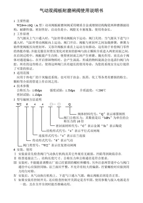
气动双阀板耐磨闸阀使用说明书1 主要性能WZ644-10Q(A型)动双阀板耐磨闸阀采用硬质合金或增韧结构陶瓷两种磨擦副结构,耐磨性强,密封性好,启动负荷小,阀腔无卡塞现象,使用寿命长。
2 工作原理当气源从上气口通入时,气缸杆带动阀板向下运动,阀门关闭。
当气源从下进气口通入时,气缸杆带动阀板向上运动,阀门开启。
阀板与密封环之间加载弹簧,弹簧力始终使阀板压向密封环,又容许阀板在垂直上运动方向移动,这有助于补偿阀门零件的热胀冷缩,并能克服任何背压变化对密封的影响与防止颗粒介质进入两密封面之间。
在启闭过程中,阀板能产生自转,使得密封面之间产生研磨、抛光作用。
而且由于阀体对通道偏心,在开启排卸物料时,会产生涡流,形成的物料旋涡会自选清扫阀门内腔。
所有的这些特点,使得这种阀门具有超长的使用寿命,为您的系统安全运行提供了可靠的保证。
3 适用范围应用于热电厂的干灰输送系统,也可用于冶金、医药、化工等各类有磨损的粉尘、颗粒等介质的管道上作启闭之用。
4 技术参数公称压力:1.0Mpa 强度试验:1.5Mpa 介质温度:≤200℃密封试验:1.1Mpa5 型号编制方法说明WZ 6 4 4 □—□Q阀体材料代号:“Q”表示球墨铸铁阀门公称压力:其数值是以“MPa”为单位的公称压力的10倍密封面材料代号:“C”表示金属“Tc”表示陶瓷结构形式代号:“4”表示平行式双闸阀连接形式代号:“4”表示法兰连接传动形式代号:“6”表示气动阀门类型号:“WZ”表示往复滑动闸阀6 安装、使用Ⅰ安装前首先检查阀门气动执行机构及其它外观有无破损,凹陷等到缺陷存在.Ⅱ检查连接法兰,、结构长度尺寸、公称压力和公称通径是符合要求。
Ⅲ安装时,不能随意调整出厂前已经紧固的螺柱和螺母。
另外注意两管道中心与阀门通径中心应保持同轴,法兰面应平整,不允许有较大的偏斜,拧紧螺栓时应做到用力均匀对称。
Ⅳ安装后,从气动执行机构上、下进气口通入气源,确认阀板启闭是否正常。

aerospaceclimate controlelectromechanicalfiltrationfluid & gas handlinghydraulicspneumaticsprocess controlsealing & shieldingParker 7321B/7322B SeriesWater ValvesHigh performance 2-ways pilot operatedsolenoid valves for water, light oils and steamParker 7321B/7322B Series Water ValvesApplicationsParker 7321B/7322B 2/2 pilot operated valves is the best solution anywhere a perfect control media such water, steam, and light oils is required.7321B/7322B Series are diaphragm pilot operated valves and require a minimum diff erential pressure to operate.Water is the basic element for human life, and water control makes possible a wide varety of human activities such as irrigation and food production, breeding, water dispensing, energy production, car and tools washing; water is the basic element in many applications like fi re-fi ghting, domotic, plumbing. Basing on solenoid technology, among the features this product provides a high fl ow rate, a fast reaction time and a superior reliability in a robust and modern design. Manual override is available to open and close the valve without electrical supply, as well as speed control option against water hammer eff ect.Our 7321B/7322B Water Valves range is usable with the most of our FCDE coil ranges, including ATEX, low power and IP67 electrical parts.Th anks to the best performances in fl ow rate,7321B/7322B Series can be used for many applications with high fl ow rates and media such as water, hot water and steam. Typical applications can befound in: Plumbing mkt, industrial washing machines,car wash installations, cooling of machine tools, hydrocleaners, autoclaves, irrigation systems, etc…Benefi tsAmong the most valuable features you can fi nd in this product:●Best performances for minimum and maximumoperating pressure diff erential●Exclusive diaphragm design for a Superior Flow Rate,higher than the competition valves with the samedimensional specs and fl at diaphragm●One of the Fastest in electrical and hydraulic opening response time●Modular concept: a wide range of electrical partsincreases the versatility of this product●Robust design: areas under mechanical stress have beenstudied and oversized●Manual override control option: valve can be easilyactivated also when there’s no energy supply●Stainless steel pilot for superior life endurance withspe c ial sealing●Easy access to internal parts, to permit easy and quick maintenan c eAE - UAE, Dubai Tel: +971 4 8127100********************AR - Argentina, Buenos Aires Tel: +54 3327 44 4129AT - Austria, Wiener Neustadt Tel: +43 (0)2622 23501-0*************************AT - Eastern Europe, Wiener NeustadtTel: +43 (0)2622 23501 900****************************AU - Australia, Castle Hill Tel: +61 (0)2-9634 7777AZ - Azerbaijan, Baku Tel: +994 50 2233 458****************************BE/LU - Belgium, Nivelles Tel: +32 (0)67 280 900*************************BR - Brazil, Cachoeirinha RS Tel: +55 51 3470 9144BY - Belarus, Minsk Tel: +375 17 209 9399*************************CA - Canada, Milton, Ontario Tel: +1 905 693 3000CH - Switzerland, Etoy Tel: +41 (0) 21 821 02 30*****************************CL - Chile, Santiago Tel: +56 2 623 1216CN - China, Shanghai Tel: +86 21 2899 5000CZ - Czech Republic, Klecany Tel: +420 284 083 111*******************************DE - Germany, Kaarst Tel: +49 (0)2131 4016 0*************************DK - Denmark, Ballerup Tel: +45 43 56 04 00*************************ES - Spain, Madrid Tel: +34 902 330 001***********************FI - Finland, Vantaa Tel: +358 (0)20 753 2500parker.fi ****************FR - France, Contamine s/ArveTel: +33 (0)4 50 25 80 25************************GR - Greece, Athens Tel: +30 210 933 6450************************HK - Hong Kong Tel: +852 2428 8008HU - Hungary, Budapest Tel: +36 1 220 4155*************************IE - Ireland, Dublin Tel: +353 (0)1 466 6370*************************IN - India, MumbaiTel: +91 22 6513 7081-85IT - Italy, Corsico (MI)Tel: +39 02 45 19 21***********************JP - Japan, Tokyo Tel: +(81) 3 6408 3901KR - South Korea, Seoul Tel: +82 2 559 0400KZ - Kazakhstan, Almaty Tel: +7 7272 505 800****************************LV - Latvia, Riga Tel: +371 6 745 2601************************MX - Mexico, Apodaca Tel: +52 81 8156 6000MY - Malaysia, Shah Alam Tel: +60 3 7849 0800NL - The Netherlands, OldenzaalTel: +31 (0)541 585 000********************NO - Norway, Ski Tel: +47 64 91 10 00************************NZ - New Zealand, Mt Wellington Tel: +64 9 574 1744PL - Poland, Warsaw Tel: +48 (0)22 573 24 00************************PT - Portugal, Leca da Palmeira Tel: +351 22 999 7360**************************RO - Romania, Bucharest Tel: +40 21 252 1382*************************RU - Russia, Moscow Tel: +7 495 645-2156************************SE - Sweden, Spånga Tel: +46 (0)8 59 79 50 00************************SG - Singapore Tel: +65 6887 6300SK - Slovakia, Banská Bystrica Tel: +421 484 162 252**************************SL - Slovenia, Novo Mesto Tel: +386 7 337 6650**************************TH - Thailand, Bangkok Tel: +662 717 8140TR - Turkey, Istanbul Tel: +90 216 4997081************************TW - Taiwan, Taipei Tel: +886 2 2298 8987UA - Ukraine, Kiev Tel +380 44 494 2731*************************UK - United Kingdom, WarwickTel: +44 (0)1926 317 878********************US - USA, Cleveland Tel: +1 216 896 3000VE - Venezuela, Caracas Tel: +58 212 238 5422ZA - South Africa,Kempton ParkTel: +27 (0)11 961 0700*****************************Parker WorldwideEuropean Product Information Centre Free phone: 00 800 27 27 5374(from AT, BE, CH, CZ, DE, DK, EE, ES, FI, FR, IE, IL, IS, IT, LU, MT, NL, NO, PL, PT, RU, SE, UK, ZA)E d . D e c e m b e r 2009Fluid Control Division Europe Parker Hannifi n S.p.A.Via Enrico Fermi, 520060 Gessate (MI) - Italia Tel.: + 39 02 95125251Fax: + 39 02 95382051*******************/fcde8810/UKYour local authorized Parker distributor© 2009 Parker Hannifi n Corporation. All rights reserved.。
劲达科技风门使用说明书使用说明书电动插板式风门德阳劲达节能科技有限责任公司劲达科技电动插板风门使用说明书目录一、概述二、特点三、结构四、电气控制与调试五、插板门、电动装置安装及使用维护注意事项劲达科技风门使用说明书一、概述插板式风门是用插板作启闭元件,并随插板上下移动,以实现全开、全关的一种阀门。
插板门在管路中主要起关断介质流量,压力、和切断通路之用。
大型高温风门一般用于烟风道和煤气管道。
广泛用于电力、水力、石油、化工、矿山等部门。
二、特点1.方便迅速、流体阻力小、可以经常操作;2.结构简单、体积小、质量轻、维修方便;3.在低压下,可以实现良好的密封,关断性能好;三、主要结构(1)插板式风门由外框架、内框架、门板、轨道、驱动装置、执行器、下部行走连接支耳、密封条等组成;(2)通风机插板式风门材料:钢板、槽钢、工字钢;(3)拉紧装置为梯形螺纹轴;(4)门枢采用滑动轴承;(5)外框架由门框、上部行走导轨、框架密封板、检修盖板、罩壳、轴封等组成。
考虑到门启闭时会产生一定的外泄露,为此外框架是全封闭的。
四、电气控制与调试1.电气原理图及电装调试详见配套电动装置厂说明书。
五、插板门、电动装置安装及使用维护注意事项<一>插板门的安装及使用维护注意事项:1.安装时门板要停止在全关闭的位置上;2.开启位置应按门板的高度来确定;3.质量大的插板门设置在牢固的基础上;4.一般为法兰式连接;5.插板门的位置允许水平布置或垂直布置。
6.运行中如轴端密封处有外泄现象,需更换法兰处密封垫片。
〈二〉电动装置安装及使用维护注意事项:1.阀门电动装置与阀门安装之前,须检查一下电动装置的接盘与轴孔尺寸是否与阀门的一致。
阀门电动装置安装位置应按要求接管,电机尽量呈水平位置,在不可避免的情况下,电机非倾斜不可时,电机的轴伸应向下倾斜,防止因以外润滑油时进入电机内部,并应把电气箱盖和导线进出密封好,以防潮气和雨水进入电气箱内,造成电气元件失效及零件锈蚀。
Principle of OperationAdjusting screw Spring Valve Piston Lower diaphragm Lower diaphragm chamber Upper diaphragm Upper diaphragm chamber Exhaust port Adjusting spring Adjusting screw Spring Valve PistonExhaust port Adjusting spring Adjusting screw Spring Valve Piston Lower diaphragm Lower diaphragm chamber Upper diaphragm Upper diaphragm chamber Exhaust port Adjusting spring OUT1OUT2Standard SpecificationsNote 1) Provide a differential pressure of 0.1 MPa or morebetween the signal pressure and set pressure.If the differential pressure is small, the internal part which may affect the characteristics.Note 2) Pressure difference between lock activated and released¡ T he lock-up valve is used if any air source or air supply piping line failure occurs in the air operated process control line.Single acting, Double acting: Retains pressure at the operating area as emergency operation until the air source is recovered to its normal state.3 Port: Changes the supply port if a trouble occurs.Lock-Up ValveSeries IL201/211/220SuffixC)C)C)C)How to OrderThe signal air pressure enters the upper diaphragm chamber q to generate a force. When this force is larger than the force generated by compressing the adjusting spring e , the upper diaphragm w is pushed up, the exhaust port r chamber t and acts the lower diaphragm y pushes down the piston u to open the valve.the status, in which the flow path between IN1 and OUT is opened. If the signal air pressure drops to a level below the set pressure for some reason, the upper diaphragm w is pushed down, the pressure inside the lower diaphragm t is exhausted from the exhaust port r , and the valve i is closed by the force of the spring o . At this time, IN and OUT and OUT are shut down, and the flow path between IN2 and OUT is opened. The set pressure is adjusted with the adjusting screw !0.56R e g u l a t o r sR E e c t r o -P n e u m a t i c T r a n s d u c e r sD e t e c t i o n o n v e r s i o n U n i ti r P r e p a r a t i o n E q u i p m e n t I p i n g M a t e r i a l sConstructionIL211IL201Series IL201/211/220DimensionsIL201Panel fitting dimensionIL220IL21158Lock-Up Valve SeriesIL201/211/220RegulatorsREectro-PneumaticTransducersDetectiononversionUnitirPreparationEquipmentIpingMaterials。
穿透式气动插板阀说明书
结构特点
穿透式气动插板阀是一种闸板与阀座始终紧密接触密封的阀门,其原理是闸板上开有一个通径大小的圆口,通过闸板启闭使得闸板上圆口跟通径做完全脱离和相吻合的动作。
此阀门的优点在于阀体通径无凹槽,介质不会卡阻堵塞,并且具有全通径流通特性,适合粉体颗粒介质的管道中使用。
其密封结构可以分软密封、硬密封结构。
穿透式插板阀是具有精密构造,工艺性好,结构紧凑等特点,密封阀座为活动结构设计,有防磨损和自动补偿功能,因而寿命更长。
在关闭和开启过程中阀座跟闸板一直紧贴运动,使得阀门启闭力稳定,并且具有切断介质等特点。
根据客户要求可配电磁阀、限位开关、过滤器等。
连接方式:法兰、螺栓连接
传动机构:气动
主要材质:WCB
闸板材质:2Cr13、201、304、316、316L
适用温度:≤300℃
泄漏等级:D级(1×DNmm3/s)
密封形式:H
填料密封:石墨盘根
适用介质:适用于矿山电厂的选煤、排渣、食品、造纸、医药、化工等管路上,接通或截断管路中的水泥浆、金矿粉、矿砂、炉渣、煤泥、纸浆、木浆、尾矿、纤维、粉尘、化学品处理污水、沉淀池、沥青、料仓出口等介质。
使用说明
一、用户在安装阀门前必须校对阀门型号、连接尺寸及注意介质流
向,保证与阀门要求一致性。
二、用户在安装阀门时,必须预留阀门驱动的必要空间。
三、驱动装置的接线须按线路进行。
四、阀门必须定期保养,不得随意碰撞挤压,以免影响密封。
C O M B U S T I O N331Features• Double solenoid gas train provides the most compact configuration for space restrictive requirements• Double Hydramotor ®gas train provides the highest flow and pressure to meet industry’s most demanding requirments • Solenoid and Hydramotor combination provides the most economical solution for slow opening applications • Optional NPT threaded flange adapters allow direct piping that simplifies the installation and maintenance • Suitable for boilers, furnaces, ovens, kilns, heatingequipment, and gas generators used in commercial and industrial applications• Low pressure drop and extremely high flow capacity, ideal in low gas supply pressure applications/locationsPlease reference 8214(200), AH(E), or V710(B) catalog pages for additional features.^ #Adapter & Connecting Hardware Kits (Optional)Approvals8214(200) valveUL listed to standard 429 “Electrically Operated Valves,”Guide YIOZ, File MP618 Safety Shutoff Valves.FM Approved to Class 7400 “liquid and gas safety shutoff valves.”CSA Certified to:1) Standard C22.2 No. 139 “Electrically Operated Valves,” File 010381.2) Automatic Gas Valves Z21.21 (6.5), C/I, File 112872.3) Automatic Gas Safety Shutoff Valves (3.9), File 112872.V710(B) valve with AH(E) HydramotorUL listed to standard 429 “Electrically Operated Valves,” Guide YIOZ, File MP932 Safety Valves FM Approved to Class 7400 “liquid and gas safety shutoff valves.”CSA Certified to:1. Automatic Gas Valves ANSI Z21.21 CSA 6.5, C/I, File 109157 and 113070.2. Automatic Gas Safety Shutoff Valves (CGA3.9), File 1130703. Standard C22.2 No. 139, File 109157 and 113070FluidFuel GasSpecifications(English units)Note:The flow values are calculated for joined double valve construction, please reference 8214(200) and V710(B) catalog pages for discrete valve flows, and optional features.Specifications (Metric units)332333Specifications (English units)Note:The flow values are calculated for joined double valve construction, please reference 8214(200) and V710(B) catalog pages for discrete valve flows, and optional features.334Specifications (English units)Note:The flow values are calculated for joined double valve construction, please reference 8214(200) and V710(B) catalog pages for discrete valve flows, and optional features.C O M B U S T I O N335Dimensions inches (mm)Adapter & Joining Hardware Kits (Optional)336。
目录
一、适用范围 (1)
二、特点 (1)
三、主要技术参数 (1)
四、安装、使用要点 (1)
五、常见故障及排除方法 (2)
六、安装尺寸及外形图 (2)
双阀板闸阀采用双阀板,密封副采用硬质合金等耐磨材料,具有较好的机械性能和耐磨性能,解决了密封面因物料冲刷而易被冲蚀、寿命不高的问题,因而具有更长的使用寿命,能为用户带来理想的使用效果和经济效益,有利于设备检修和运行调节,从而使整体运行的安全性、经济性明显提高。
一、适用范围
用于热电厂干灰系统仓泵进出料阀,也可用于矿山、造纸、化工等各类有磨损的干粉尘、水、蒸汽等介质的管道上作启闭之用。
二、特点
1、料口全流通无阻挡物,有吹堵装置,卡灰、积灰现象少。
2、耐磨性好,使用寿命长。
3、可任意位置、角度安装。
4、结构紧凑、安装方便。
5、密封填料自调整装置。
三、主要技术参数
公称压力:1.0MPa 介质温度:≤200℃
强度试验:1.5MPa 密封试验:1.1MPa
四、安装、使用要点
1、安装前应仔细阅读本说明书,并核对阀门型号、通径及技术参数。
2、严禁装上阀门后施焊法兰。
管道自先预留的阀门安装距离应适当,法兰两边
加垫片。
3、两管道中心与阀门通径中心应保持同轴,法兰面应平整,不允许法兰面有较
大的偏斜,以保证阀门的夹紧和正常工作。
拧紧螺栓应做到均匀对称。
五、常见故障及排除方法
六、安装尺寸及外形图。