DN150眼镜阀说明书new
- 格式:doc
- 大小:1.14 MB
- 文档页数:5
电动扇形盲板阀永嘉瓯北双金阀门有限公司结构特点及用途:电动扇形盲板阀主要由左阀体、右阀体、丝阀体、翻板、密封圈、杠杆、液压油缸等零件组成,并由底座、支撑柱构成一个钢性结构体。
阀体中没有夹紧油缸和翻板油缸,夹紧油缸通过杠杆副和丝杠螺旋副驱动左、右阀体完成松开、夹紧动作,翻板油缸驱动翻板完成开关动作。
橡胶密封圈镶嵌在翻板上,具有耐高温、密封性能好、更换方便、使用帮命长等特点。
本阀体可以单台远距离控制,亦可多台联网远距离控制,非正常情况下还可以利用阀门本身装置手动操作。
F943X- 型主要外形及连接尺寸表0.5、1.5 1.0、2.5结构特点及用途: 本系列眼镜按GB6222《工业企业煤气安全规程》的有关标准同时消化吸收国内外先进技术基础上,自行研究开发的新一代产品,广泛适用于工矿企业、环境保护等行业的煤气、有毒气体介质管理中,作为可靠的切断装置。
主要性能参数:主要零件材质:技术性能:本阀有左右阀体、扇形阀板、不锈钢波纹管、电动驱动装置、电动夹紧装置等部件组成。
阀体采用三点式锁紧扇形阀板结构。
密封部位采用不锈钢与橡胶密封圈,密封性能好,使用寿命长,密封圈设在阀板上,便于维护时更换密封圈。
电动操作、工作平稳、启动灵活、动作可靠。
夹紧机构采用丝杆螺母副进行夹紧,自锁性好。
电动眼镜阀设有不锈钢波纹管,具有伸缩性强,使用寿命长等特点。
安装及使用说明:本阀安装完毕后,应做支架固定阀门底座,在动作时阀门受力于支架上。
首先启动电动夹紧装置把左右阀体位移阀体和阀板完全脱离,在开启阀板电动装置阀板开启或关闭,随后再启动电动夹紧装置,检查左右阀体是否紧贴在阀体上及电动装置动作时限位开关是否动作。
F943X- 电动扇形盲板阀主要外形及连接尺寸表0.5 1.0 2.5。
150TQ/PVⅡ347F-150AS型清管阀使用说明书西安泵阀总厂有限公司一. 清管阀介绍清管阀是一种被广泛应用于石油、天然气管线的阀门,它的主要用途是通过对清管器的发射或接收,来清理输送天然气、油品等介质的管线。
过去石油天然气行业,对输送气液管线的清理常采用由发射筒、接收筒、阀门组、压力表、传动机构、安全阀等组成的发射、接收组合装置。
通过这种组合装置对清管器的发送与接收来清理管线。
我厂生产的清管阀是国家专利产品,专利号ZL97239827.9。
其可以在介质不断流的情况下,通过介质压力作用在清管器上,对清管器进行发射和接收,达到清理管线的作用。
现在,只用一台清管阀就可以达到以前由一组组合装置完成的工作。
清管阀的使用首先可以简化管路,提高现场的工作效率,同时清管阀又具有体积小、操作简单等优点。
使采用发射、接收组合装置所造成的装置占地面积大、制造费用高、操作麻烦、费时等缺点得到全面的改善。
二适用范围和性能规范:1本阀适用于温度在-29℃~121℃的石油、天然气、油品等介质的管道上,做清管器的发射或接收用。
2 性能规范:公称压力PN(MPa): 15公称通径DN(mm): 150工作温度: -29℃~121℃压力试验:按JB/T9092-99的规定,并按Q/XGF2011-2005的有关规定进行防静电试验。
三工作原理和结构说明:1工作原理:清管器在介质作用下被本阀接收或发射。
工作原理示意图(俯视图)如下:(1) 清管器发射:正常工作状态1.确保平衡阀开启状态;顺时针旋转手动装置手轮,使手动装置的指针应指向“关”2.关闭平衡阀(注:本阀平衡阀在左上端)3. 将前端卸压球阀完全打开卸压,再打开后端卸压球阀4.完全卸压后,逆时针旋转快卸盖手柄,打开快卸盖5.装入清管器(注意清管器装入方向)6.顺时针旋转快卸盖手柄,关闭快卸盖 7.关闭前后卸压球阀 8.打开平衡阀9.逆时针旋转手动装置手轮,使手动装置的指针指向“开” 10.发射清管器介质流向(2)清管器接收:介质流向1.确保平衡阀处于开启状态;顺时针旋转手动装置手轮,使手动装置的指针指向“关”2.关闭平衡阀3. 将前端卸压球阀完全打开卸压,再打开后端卸压球阀4.完全卸压后,逆时针旋转快卸盖手柄,打开快卸盖5.取出清管器6. 顺时针旋转快卸盖手柄,关闭快卸盖7.关闭前后卸压球阀8.打开平衡阀9.逆时针旋转手动装置手轮,使手动装置的指针指向“开”,恢复正常工作状态。

![各种阀门说明书[1]](https://uimg.taocdn.com/34d2b918fad6195f312ba62c.webp)
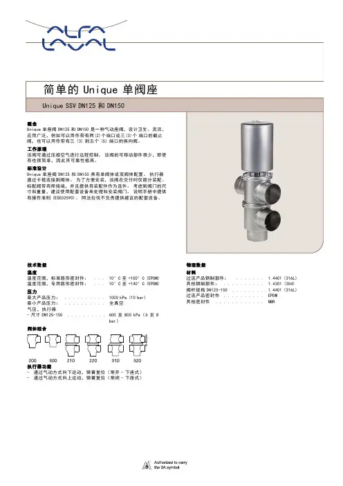
技术数据温度温度范围,标准唇形密封件:...10°C至+100°C(EPDM)温度范围,专用唇形密封件:...10°C至+140°C(EPDM)压力最大产品压力:..........1000kPa(10bar)最小产品压力:..........全真空气压,执行器-尺寸DN125-150..........600至800kPa(6至8bar)阀体组合执行器功能-通过气动方式向下运动,弹簧复位(常开-下座式)-通过气动方式向上运动,弹簧复位(常闭-下座式)物理数据材料过流产品钢制部件:....... 1.4401(316L)其他钢制部件:.......... 1.4301(304)阀杆规格DN125-150.........1.4401(316L)过流产品密封件..........EPDM其他密封件............NBR选件A.符合所要求标准的外螺纹部件。
B.控制和指示(IndiTop、ThinkTop 或ThinkTop Basic)。
C.过流产品部件的表面粗糙度:Ra ≤0.8µm。
D.NBR 或FPM 过流产品密封件。
E.执行器维修工具。
F.阀塞密封件NBR/FPM。
执行器保修期为5年尺寸(mm)DIN DN125150标称尺寸NC NO NC NO A 1571573584586A 2614618627631A 3740737777775A 4781778818816C 167167192192OD 129129154154ID 125125150150t 2.0 2.0 2.0 2.0E 1150150150150E 2150150150150F 143454345F 241414141H199199199199M/DIN 外螺纹46465050重量(kg)-截流阀40.340.340.940.9重量(kg)-换向阀505051.351.3a.截流阀。
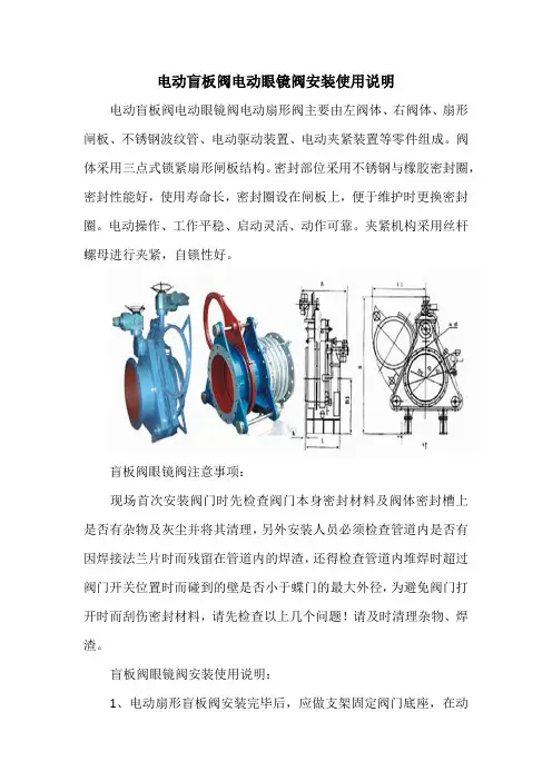
电动盲板阀电动眼镜阀安装使用说明
电动盲板阀电动眼镜阀电动扇形阀主要由左阀体、右阀体、扇形闸板、不锈钢波纹管、电动驱动装置、电动夹紧装置等零件组成。
阀体采用三点式锁紧扇形闸板结构。
密封部位采用不锈钢与橡胶密封圈,密封性能好,使用寿命长,密封圈设在闸板上,便于维护时更换密封圈。
电动操作、工作平稳、启动灵活、动作可靠。
夹紧机构采用丝杆螺母进行夹紧,自锁性好。
盲板阀眼镜阀注意事项:
现场首次安装阀门时先检查阀门本身密封材料及阀体密封槽上是否有杂物及灰尘并将其清理,另外安装人员必须检查管道内是否有因焊接法兰片时而残留在管道内的焊渣,还得检查管道内堆焊时超过阀门开关位置时而碰到的壁是否小于蝶门的最大外径,为避免阀门打开时而刮伤密封材料,请先检查以上几个问题!请及时清理杂物、焊渣。
盲板阀眼镜阀安装使用说明:
1、电动扇形盲板阀安装完毕后,应做支架固定阀门底座,在动
作时阀门受力于支架上。
首先启动电动夹紧装置把左右阀体位移,阀体和闸板完全脱离,在开启闸板电动装置,闸板开启或关闭,随后再启动电动夹紧装置,检查左右阀体是否紧贴在阀体上及电动装置工作时限位开关是否工作。
2、橡胶密封圈不得与阀体粘连或发生硬摩擦,以防止损坏橡胶密封圈,破坏阀门的工作性能。
3、扇形盲板阀为敞开式阀门,左右阀体松开时,介质要外溢,为确保安全,在关闭时,请先关闭眼镜阀前的煤气蝶阀,请采用通风和其它能保证安全的措施,同时建议阀板下不能站人,以防万一造成人员伤害。
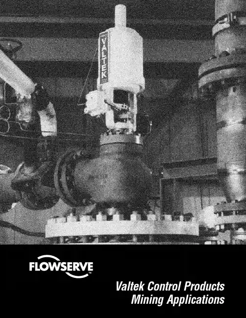
Mining ApplicationsMining ApplicationsMining precious metals today requires more technology than ever before. With the known world deposits of gold shrinking, the mining industry is squeezing as much metal as possible from each ton of ore. As we use up the richer deposits we are required to use more arduous methods such as high-pressure acid leaching which result in severe operating conditions.To increase productivity, the industry continues to look for new and innovative ways to increase output from the refractory ore deposits available. New processes and the refinement of existing operations are more impor-tant today than ever before. Leaching, rotary kiln and now pressure oxidation processes have been devel-oped over the years to extract more metal from every ton of ore. As each successive process is developed,the pressures and temperatures become harsher,sometimes reaching 450 psi / 3100 kPa and 650° F /343° C and higher.StarPac II on a Valtek Mark One controlling flow on an oxygen sparge into an autoclave.Survivor and Shear Stream ceramic ball valves used in erosive vent applications.ing new ideas – looking for progressive designs and using innovative technologies to handle severe ser-vices. Working closely with industry leaders, they routinely custom design products for specific processes.Flowserve is known for its innovative approach to tough applications. Flowserve engineers are always pursu-Mining ApplicationsWith years of experience machining various metals (titanium, zirconium, Ferralium TM and Inconel TM ) and the application of ceramic components, Flowserve has extended the valve-life in many tough erosive and corrosive mining applications. Our engineers helped pioneer the use of ceramic materials in control valves At the same time, Flowserve’s basic valve advantages are maintained: high thrust cylinder actuators with stiff throttling capabilities, protected stem designs for long-life operation, and excellent rangeability for responsive and accurate control in severe applications with long durability. In addition, high parts interchangeability means reduced parts stocking requirements and faster repair capabilities.Today, Valtek control valves are used extensively throughout the mining process, from light applications to severe service systems. In the carbon-in-leach process, the standard Valtek Mark One TM control valve helps maintain an accurate mixture of carbon particles and cyanide. In the oxidative pressurization circuit, the sweep-angle body Survivor TM valve is used to let down the 50 percent solids slurry from the autoclave through a 300 psi / 20.7 bar pressure drop. The ceramic-lined ShearStream TM ball valve controls particle-entrained steam vent lines.In addition, Flowserve uses the advanced StarPac technology to precisely control the flow of oxygen spurges. Also, the Logix 1000 Series allows precise control of stem position on the autoclave letdown ing a team approach, Flowserve and many of its customers have developed new product variations to meet the needs of an increasingly complex process for recovering precious metals from ore.Logix 1200 on a Valtek Survivor Valve in a high-pressure flash letdown application.Erosive service ShearStream controlling on solids-laden abrasive steam.Mining Applications Typical ApplicationsValtek SurvivorFeatures•Sweep-angle and large gallery design decreases fluid velocity and minimizes impingement of par-ticles on valve body •Ceramic trim provides durable control in flashing slurry or other high velocity erosive applications •Venturi seat design safely channels the slurry into flash vessels; protects valve body from erosive damage caused by high velocities •Wiper rings and purged bonnet restrict particles suspended in fluids from entering the bonnet,reducing damage to guides and surfaces, prevent-ing stem seizureSpecificationsMining ApplicationsMining Applications SpecificationsValtek Mark OneFeatures•Corrosion resistant materials provide long-life operation in harsh services•Adaptability of trim for changing conditions and applications•Double top-stem guiding designed out of stream,prevents fluid particulate from galling stem •Large stem diameter ensures shutoff and no galling or sticking•Wide application in both liquids and gases •Serve service trim availableMining ApplicationsMining Applications©1999 Flowserve Corporation. Flowserve Corporation, Valtek Control Products, Tel. USA 801 489 8611Rev. 3/99Flowserve Corporation has established industry leadership in the design and manufacture of its products. When properly selected, this Flowserve product is designed to perform its intended function safely during its useful life. However, the purchaser or user of Flowserve products should be aware that Flowserve products might be used in numerous applications under a wide variety of industrial service conditions. Although Flowserve can (and often does) provide general guidelines, it cannot provide specific data and warnings for all possible applications. The purchaser/user must therefore assume the ultimate responsibility for the proper sizing and selection, installa-tion, operation and maintenance of Flowserve products. The purchaser/user should read and understand the Installation OperationMaintenance (IOM) instructions included with the product, and train its employees and contractors in the safe use of Flowserve products in connection with the specific application.While the information and specifications presented in this literature are believed to be accurate, they are supplied for informative purposes only and should not be considered certified or as a guarantee of satisfactory results by reliance thereon. Nothing contained herein is to be construed as a warranty or guarantee, express or implied, regarding any matter with respect to this product. Because Flowserve is continually improving and upgrading its product design, the specifications, dimensions and information contained herein are subject to change without notice. Should any question arise concerning these provisions, the purchaser/user should contact Flowserve Corporation at any of its worldwide operations or offices.For more information, contact:For more information about Flowserve and its products,contact or call USA 972 443 6500Regional Headquarters 1350 N. Mt. Springs Prkwy.Springville, UT 84663Phone 801 489 8611Facsimile 801 489 371912 Tuas Avenue 20Republic of Signapore 638824Phone (65) 862 3332Facsimile (65) 862 494012, av. du Québec, B.P. 64591965, Courtaboeuf Cedex, France Phone (33 1) 60 92 32 51Facsimile (33 1) 60 92 32 99Quick Response Centers 5114 Railroad StreetDeer Park, TX 77536 USA Phone 281 479 9500Facsimile 281 479 8511104 Chelsea ParkwayBoothwyn, PA 19061 USA Phone 610 497 8600Facsimile 610 497 66801300 Parkway View Drive Pittsburgh, PA 15205 USA Phone 412 787 8803Facsimile 412 787 1944Flowserve and Valtek are registered trademarks of Flowserve Corporation.。
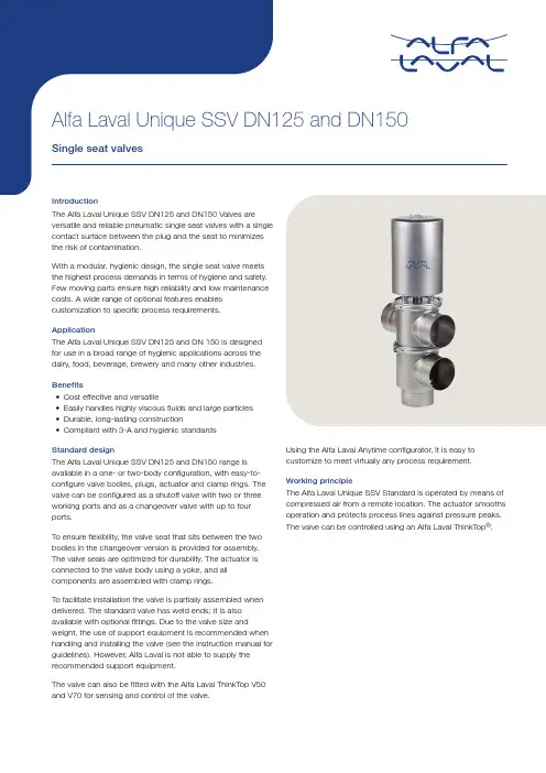
Standard designThe Alfa Laval Unique SSV DN125 and DN150 range is available in a one- or two-body configuration, with easy-to-configure valve bodies, plugs, actuator and clamp rings. The valve can be configured as a shutoff valve with two or three working ports and as a changeover valve with up to four ports.To ensure flexibility, the valve seat that sits between the two bodies in the changeover version is provided for assembly. The valve seals are optimized for durability. The actuator is connected to the valve body using a yoke, and all components are assembled with clamp rings.To facilitate installation the valve is partially assembled when delivered. The standard valve has weld ends; it is also available with optional fittings. Due to the valve size and weight, the use of support equipment is recommended when handling and installing the valve (see the instruction manual for guidelines). However, Alfa Laval is not able to supply the recommended support equipment.The valve can also be fitted with the Alfa Laval ThinkTop V50 and V70 for sensing and control of the ing the Alfa Laval Anytime configurator, it is easy to customize to meet virtually any process requirement.Working principleThe Alfa Laval Unique SSV Standard is operated by means of compressed air from a remote location. The actuator smooths operation and protects process lines against pressure peaks. The valve can be controlled using an Alfa Laval ThinkTop®.TECHNICAL DATAMin. product pressure:Full vacuumAir pressure, actuator - Sizes DN125-150600 to 800 kPa (6 to 8 bar)Valve body combinations2200-0179200300210220310320Actuator function•Pneumatic downward movement, spring return (NO-lower seat)•Pneumatic upward movement, spring return (NC-lower seat)PHYSICAL DATAOther steel parts:1.4301 (304)Plug stem sizes DN125-150: 1.4401 (316L)Product wetted seals:EPDM Other seals:NBROptions •Male parts in accordance with required standard•Control and Indication (IndiTop, ThinkTop or ThinkTop Basic)•Surface roughness, product wetted parts: Ra ≤ 0.8 µm •Product wetted seals of NBR or FPM •Service tools for actuator •Plug seals NBR/FPMDimensions (mm)Figure 1. Shut-offFigure 2. Change-over valve1A2614618627631 A3740737777775 A4781778818816 C167167192192 OD129129154154 ID125125150150 t 2.0 2.0 2.0 2.0 E1150150150150 E2150150150150 F143454345 F241414141 H199199199199 M/DIN male46465050 Weight (kg) - Shut-off valve40.340.340.940.9 Weight (kg) - Change-over valve505051.351.3Please note!Opening/closing time will be effected by the following:•The air supply (air pressure).•The length and dimensions of the air hoses.•Number of valves connected to the same air hose.•Use of single solenoid valve for serial connected air actuator functions.•Product pressure.Air Connections Compressed air:R 1/8" (BSP), internal thread.Actuator functionShut-off / Change-over valve Actuator functionNC NOShut-off / Change-over valve Actuator function 3.6 x Air pressure (bar) 2.9 x Air pressure (bar)NC (Support air for closing)NO (Support air for opening)Pressure drop/capacity diagrams50454035302520151050Q [m³/h)A = DN125B = DN150P [kPa]Figure 3. Shut-off50454035302520151050Q [m³/h)A = DN125B = DN150P [kPa]Figure 4. Shut-off50454035302520151050Q [m³/h)A = DN125B = DN150P [kPa]Figure 5. Change-over valve50454035302520151050Q [m³/h)A = DN125B = DN150P [kPa]Figure 6. Change-over valve50454035302520151050Q [m³/h)A = DN125B = DN150P [kPa]Figure 7. Change-over valve5045403530252015105020Q [m³/h)A = DN125B = DN150P [kPa]Figure 8. Change-over valveNote!For the diagrams the following applies:Medium: Water (20 °C)Measurement: In accordance with VDI 2173Pressure drop can also be calculated in Anytime configurator Pressure drop can also be calculated with the following formula:Q = Kv x √Δp Where:Q = Flow in m 3/hKv = m 3/h at a pressure drop of 1 bar (see table above)Δ p = Pressure drop in bar over the valveHow to calculate the pressure drop for an ISO 2.5" shut-off valve if the flow is 40 m 3/h2.5" shut-off valve, where Kv = 111 (See table above)Q = Kv x √Δp 40 = 111 x √Δp0.13 bar (This is approx. the same pressure drop by reading the y-axis above)Pressure data for Unique Single Seat Valve DN125 and DN150Figure 9. 1Figure 10. 2Figure 11. 3Figure 12. 4Actuator type / function10. Pneumatic downward movement, spring return (NO-lower seat)20. Pneumatic upward movement, spring return (NC-lower seat)Stop and change-over valvesFigure 10. 25NO DIN 8.76NO DIN 4.4Figure 11. 35NC 8.1*6NC 3.7Figure 12. 4NCDIN5.2Figure 13. 5Figure 14. 6Figure 15. 7Figure 16. 8= Values are valid for 8 bar air pressure = Actual product pressureStop and change-over valvesFigure 14. 6610 (NO) 8.1660 (NO)min. 10Figure 16. 820 (NC)8.9Max. pressure in psi against which the valve can openopens87.6NC 145.0opensNO 145.0This document and its contents are subject to copyrights and other intellectual property rights owned by Alfa Laval Corporate AB. No part of this document may be copied, re-produced or transmitted in any form or by any means, or for any purpose, without Alfa Laval Corporate AB’s prior express written permission. Information and services provided in this document are made as a benefit and service to the user, and no representations or warranties are made about the accuracy or suitability of this information and these services for any purpose. All rights are reserved.200004004-3-EN-GB© Alfa Laval Corporate ABHow to contact Alfa LavalUp-to-date Alfa Laval contact details for all countries are always available on our website at 。
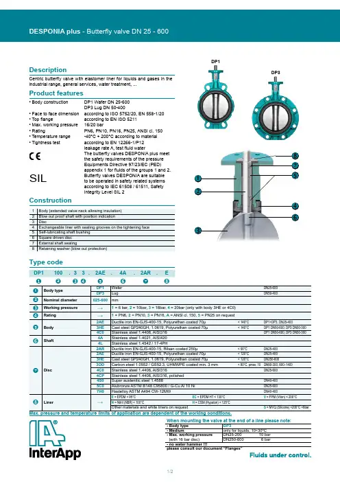
1/2DP1DP3❺❻❼❽❷❶❹❸DP1100.33.2AE.4A.2AR.EDescriptionCentric butterfly valve with elastomer liner for liquids and gases in the industrial range, general services, water treatment, ...ConstructionProduct features• Body construction DP1 Wafer DN 25-600DP3 Lug DN 50-400• Face to face dimension according to ISO 5752/20, EN 558-1/20• Top flangeaccording to EN ISO 5211• Max. working pressure 16/20 bar• RatingPN6, PN10, PN16, PN25, ANSI cl. 150• Temperature range -40°C ÷ 200°C according to material • Tightness testaccording to EN 12266-1/P12leakage rate A, test fluid waterThe butterfly valves DESPONIA plus meet the safety requirements of the pressure Equipments Directive 97/23/EC (PED) appendix 1 for fluids of the groups 1 and 2.SILButterfly valves DESPONIA are suitable to be operated in safety related systems according to IEC 61508 / 61511, Safety Integrity Level SIL 2Type codeWhen mounting the valve at the end of a line please note:- Body type DP3- Medium only for liquids, 10÷30ºC - Max. working pressure (with 16 bar disc)DN25-20010 barDN250-600 6 bar - no water hammerplease consult our document “Flanges”Max. pressure and temperature limits of application are dependent of the working conditions.2/2DESPONIAplus_1138© 2011 InterApp AG, all rights reserved InterApp AG Grundstrasse 24CH-6343 RotkreuzPhone +41 (0) 41 7982233Fax +41 (0) 41 7982234****************.netInterApp GermanyAVK Mittelmann Armaturen Schillerstrasse 50D-42489 WülfrathPhone +49 (0) 2058 901 01Fax +49 (0) 2058 901 110**********************InterApp Austria Kolpingstrasse 19A-1230 WienPhone +43 (0) 1 6162371-0Fax +43 (0) 1 6162371-99****************.netInterApp Italy Via Gramsci 29I-20016 Pero (MI)Phone +39 02 339371Fax +39 02 33937200****************.netInterApp VálvulasCalderón de la Barca 12E-28860 Paracuellos de Jarama Phone +34 (0) 91 6584360Fax +34 (0) 91 6581430****************.netAVK VálvulasPoligono Industrial Francoli, parcela 27E-46006 Tarragona Phone +34 977 543 008Fax +34 977 541 622*******************InterApp Singapore11, Changi North Street 1, #03-11Singapore 498823Phone +65 62141048Fax +65 62140481****************.netDN25/32DN40/50/65DN80/100DN125/150/200DN450-600DN250-400DN 450-600DN 25-400enThe technical data are noncommittal and do not assure you of any properties. Please refer to our general sales conditions. Modifications without notice.DimensionsDP1 Wafer, DN 25-600DP3 LUG body, DN 50-400Top flange according to EN ISO 5211Further documentationPneumatic actuators, Electric actuators, Accessories according separate data sheets.Installation guide, Maintenance guide, Flanges : Please consult these guides for the installation and maintenance of our butterfly valves.。
SUNGO VALVES GROUP CO.,LTD闸阀Gate ValveCLASS 150/300/400/600/900/1500/2500# API 600 API 602闸阀使用说明书GATE VALVE OPERATING INSTRUCTIONS闸阀使用说明书Gate Valve Operating Instruction安装1.细心的拆卸阀门的包装物,对照材料,规范和明细表等清单,检查标签和标牌。
查看所选用的阀门型号,法兰尺寸,结构长度是否与系统的压力,温度等条件相适应。
2.检查阀门内部是否清洁,有无异物和危害性的腐蚀,如有请进行清洗干净后进行安装。
3.手轮操作的双闸板闸阀应直立安装(即阀杆处于垂直的位置,手轮在顶部),手动单闸板闸阀和泄压的高磅级的闸阀可安装在管道的任意位置上(见附图)。
4.手轮及传动机构不允许做起吊用。
5.阀门安装好后,请用水清洗管道,去除安装时可能带来的废物,以防止密封面被划伤。
6.对于法兰连接,对接焊,承插焊的阀门的具体安装步骤及注意事项请查阅〈〈MSS阀门用户指南〉〉。
7.安装时,要注意带泄压的高磅级闸阀必须保证介质的流向和阀体上的箭头方向保持同向。
操作1.闸阀是一种截断阀,用来接通和截断管路中的介质,应全开或全闭使用,不能用于调节流量。
2.手动操作的闸阀,顺时针旋转时为关闭阀门,逆时针旋转为开启阀门。
3.禁止在带压的情况下更换填料。
4.手动阀门的手轮按操作阀门所需开,关力矩进行设计,制造,用户不得借助辅助杠杆或其他工具来加大开关力矩。
5.对于电动阀门,电动装置的工作原理及操作说明请查阅相关的电动装置说明书保养1.每月定期给阀杆,阀杆螺母的梯形螺纹部分加注润滑油,以使螺纹旋合轻松。
2.定期检查密封面的磨损情况,如有损坏,及时进行修复或更换。
3.每月定期检查填料的磨损情况,如损坏或失效,应及时更换。
4.由于阀门长期保持在某个位置不动,会使阀杆螺母失去有效的润滑,填料老化,运动部件表面腐蚀等问题,所以我们建议客户最好要制定周期性的部分或全部循环操作计划。
手动扇形翻板阀使用说明一、概述眼镜阀又名扇形眼镜阀、扇形盲板阀、翻板阀、扇形阀,广泛用于工矿企业、市政、环保等行业的气体介质管理系统中,尤其适用于有害、有毒、易燃气体的绝对切断。
亦适宜做管道终端的盲板,以缩短检修时间或方便连接新的管路系统。
根椐不同规格采用不同的结构形式,以适应用户的能源条件、环境条件和工况条件的要求。
眼镜阀与其他在管道中做绝对切断的阀门设备比较,具有结构新颖、重量轻、体积小、操作方便、动作迅速、切断气体性能绝对可靠的特点。
二、结构特点眼镜阀主要由左阀体、右阀体、丝杆夹紧机构、阀板、伸缩机构等零件组成,阀门中设有阀体夹紧装置,阀体夹紧装置通过螺杆螺旋副驱动左右阀体完成松开、夹紧动作。
橡胶密封圈镶嵌在左右阀体或翻板上,具有耐高温、密封性能好、更换方便、使用寿命长等特点。
三、眼镜阀的结构形式眼镜阀分为短系列与长系列两种,长系列眼镜设有伸缩器、一般使用于较长管路中。
其伸缩器不能替代管网中应有的膨胀节,由于管道热胀冷缩等因素产生的外力,不得传递、施加于该伸缩器上,以防止对翻板阀产生不利影响。
短系列眼镜阀橡胶圈安装在左右阀体的密封面上,而长结构眼镜阀橡胶圈安装在阀板上,可以方便的更换密封圈。
短系列眼镜阀(一般用于小口径管道)长系列眼镜阀(一般用于大口径管道)四、眼镜阀的操作操作时依次旋动三个夹紧螺栓,使阀体与阀板分离有均衡、适量的间隙,确认后转动阀板扳到工作位置。
反向旋动夹紧螺栓,使阀板与阀体紧密接触,气体介质不外泄漏。
操作时务必注意:1.密封橡胶圈不得与阀体或阀板粘连或发生硬磨擦,以防止损坏橡胶密封圈,破坏阀门的工作性能。
2.旋动夹紧螺栓使阀体与阀板分离的间隙要均匀,间隙差异不得超过1mm。
3.旋动夹紧螺栓使阀体与阀板夹紧的间隙要均匀,间隙差异不得超过0.2mm。
4.眼镜阀活动部位应注意定期加油,每月加注润滑油(脂)一次,尤其夹紧螺栓、阀板转动部位更应保证润滑,以防止开启、关闭力矩增加,动作沉重。
使用说明书OPERATION MANUAL
名称:铸钢球阀
150Lb~600Lb
规格尺寸:1/2~2”(DN15~DN50)
一、用途:
本阀门应用在石油、石油化工和相关的工业管线上控制阀门,维持系统的正常运行。
二、储存、维护、安装和使用
1.阀门应该存放在干燥通风的室内。
阀门两端须堵塞,阀门长期存放应定期检查和清洁密封面,在加工表面涂防锈油。
2.阀门安装后应定期检查和维修:密封面、阀杆和阀杆螺母、填料、垫片。
3 安装前应清洗干净。
4安装时必须仔细核对阀门上的进口箭头和铭牌是否符合使用要求。
5阀门可安装于任何位置,但须便于操作和检修。
6传动部位要保持清洁,并要定期润滑。
7必须注意:手柄顺时针关,逆时针开。
三、可能发生的故障及消除办法:
1填料过久失效,应更换填料。
2填料未压紧,应均匀地拧紧填料压板上的螺钉。
3填料数量不够,应增加填料。
4密封面处夹有污物,应清洗干净。
5密封面有损伤,应重新研磨或重新加工。
6体盖垫片压的不紧,或松紧不均匀,应均匀压紧垫片。
7垫片损坏,应更换垫片。
1。
阀门安装、使用、维护说明1.阀门安装前要核对阀门上的标识内容与所要领用的阀门要求是否相符。
2.阀门安装前要检查1阀门、管道的内腔是否有残砂、杂物,必须保持阀腔和管道内部清洁。
2阀门法兰密封面是否被破坏,如被破坏,必须修复,修复后还达不到要求的必须更换,确保法兰连接的密封性。
3阀门部件间连接的螺栓是否拧紧。
4阀门的手柄或手轮转动是否灵活。
3.重量大,人工不能搬运的阀门必须按照阀门生产供应商提供的起吊方式吊装。
4.阀门在安装过程中对单向介质流向的阀门必须按阀门上介质流向箭头方向安装。
5.阀门在使用过程中启闭扭矩要适当,一般情况不要使用加力扳手,以免损坏阀杆和手轮。
6.阀门在使用过程中如有故障需要维修必须由专业人员操作,在维修前必须切断管道内部压力,排除管道内部介质,有必要时将阀门拆出管道进行修理。
具体修理规范如下:铸钢、铸铜阀体和PN≤1.6MPa、DN≥80的灰铸铁、球墨铸铁的阀体,有裂纹或液压强度试验渗漏时,可以按规定的工艺规程进行焊补。
阀体均匀腐蚀深度达到厚度的30%、阀体法兰有裂纹、端面腐蚀无法修整和焊补后再次液压强度试验仍然渗漏的阀体,均予换新。
●阀体法兰用切削方法消除腐蚀、裂纹或翘曲,减薄厚度不得大于原始厚度的20%。
●钢、铜阀座,当PN≤1.6MPa、DN≥80的灰铸铁、球墨铸铁的阀座,有裂纹或与阀体密合部有环状腐蚀时允许补焊、研磨,无法修复时换新。
●经焊补的阀件,应做退火处理,以消除内应力。
焊补处应光滑。
●阀座磨损高度超过原高度的50%以上,或经多次加工影响密合强度的应换新。
●阀座经精车及研磨后,阀座与阀体结合部有松动或渗漏时,应另配阀座。
●阀盘密封面磨损时,允许光车研磨,PN≤1.6MPa、DN≥80的阀盘密封面,磨损高度超过原高度80%,应换新。
●当PN>1.6MPa、DN<80的灰铸铁、球墨铸铁的阀体、阀盘,有裂纹、环状腐蚀时换新。
●阀杆弯曲时,允许矫正,轻微腐蚀的进行光车,阀杆与密封衬套间隙过大或阀杆腐蚀影响密封时,应与换新。
电动盲板阀产品使用说明书浙江日高阀门有限公司一、产品概述本系列盲板阀,系GB6222-2005«工业煤气安全规程»要求的可靠切断气体介质的设备。
应用于工矿企业、市政、环保等行业的气体介质管道系统中。
尤其适用于有害、有毒、易燃气体的绝对切断。
亦适宜做管道终端的盲板,以缩短检修时间或方便连接新的管路系统。
该盲板阀有气动、液动、电动、电液动、手动等驱动方式。
并根椐不同规格采用不同的结构形式。
以适应用户的能源条件、环境条件和工况条件的要求。
该系盲板阀与其他在管道中做绝对切断的阀门设备比较,具有结构新颖、重量轻、体积小、操作方便、动作迅速、切断气体性能绝对可靠的特点。
二、主要性能主要零件材质三、结构特点该阀主要由左阀体、右阀体、丝杆副、翻板、密封圈、杠杆、装置等零件组成,并由底座、支撑柱构成一个刚性结实构体。
阀门中设有阀体夹紧装置和阀板移动装置,阀体夹紧装置通过杠杆副和丝螺旋副驱动左右阀体完成松开夹紧动作,阀板移动装置驱动翻板完成开关动作。
橡胶密封圈镶嵌在翻板上,具有耐高温、密封性能好、更换方便、使用寿命长等特点。
四、产品外形结构图01左阀体02阀板03密封圈04右阀体05阀杆06阀门底座07阀板移动装置08阀体夹紧装置四、安装注意盲板阀在开启时左、右阀体应有16-20mm的轴向位移。
因此,管路在阀门开启闭的过程也应具有满足上述位移的弹性变形或位移空间,建议按下述形式安装。
盲阀在能够保证管道外力不作用于阀门上的情况下对安装位置不做规定。
本阀不得承受由于管道热胀冷缩或其它原因发生的外力对其产生推拉扭曲作用,长结构型的伸缩器只用于阀门本身的启闭,不能代替管路中应设有的彭胀器。
管道中各种因素产生的外力也不应作用于该伸缩器。
五、操作方法:首先启动阀体夹紧装置,夹紧装置通过丝杆和左、右旋螺母的驱动使阀体和阀板完全脱离;再开启阀板移动装置,使阀板沿轴旋转,由盲孔变为通孔达到阀门开的目的,随后再启动阀体夹紧装置,检查左右阀体、阀板是否贴紧及电动装置动作时限位开关是否动作。
9410 - 20 Ave N.W.Edmonton, Alberta, Canada T6N 0A4Tel: (780) 437-9100 / Fax: (780) 437-7787June 05, 2020ES SERIES RSBFV CL.150 BUTTERFLY VALVES (1.5"-48")TORONTO, ON M9W 6N9345 CARLINGVIEW DRIVECRN :Drawing No. :Accepted on:0C22405.52Reg Type:NEW DESIGN May 07, 2030June 05, 2020Design registered in the name of : A-T CONTROLS INC Expiry Date:P03252Fitting type:Attention:The design submission, tracking number 2020-02867, originally received on June 02, 2020 was surveyed and accepted for registration as follows:Sincerely,DICK, ASHLING, P. Eng.TECHNICAL STANDARDS & SAFETY AUTHORITY Tanya FrancisIf you have any question don't hesitate to contact me by phone at (780) 433-0281 ext 3337 or fax (780)****************************.The registration is conditional on your compliance with the following notes:** See attached List of Plant Sites** See drawing P03252 for manufacturer's logo as it will appear on the fittingAs indicated on AB-41 Statutory Declaration form and submitted documentation, the code of construction are B16.34 and B16.42.- It is our understanding that the fitting(s), included as the scope of this submission, that is(are) subject to the Safety Codes Act shall comply with the requirements of the indicated Standard or Code of Construction on the AB-41 Statutory Declaration as supported by the attached data which identifies the dimensions, materials of construction, press./temp. ratings and the basis for such ratings, and the identification marking of the fittings.- This registration is valid only for fittings fabricated at the location(s) covered by the QC certificate attached to the accepted AB-41 Statutory Declaration form.- This registration is valid only until the indicated expiry date and only if the Manufacturer maintains a valid quality management system approved by an acceptable third-party agency until that date.- Should the approval of the quality management system lapse before the expiry date indicated above, this registration shall become void.DOP Cert. No. D0*******An invoice covering survey and registration fees will be forwarded from our Revenue Accounts.Page 1 of 12020-02867ABSASAFETY CODES ACT - PROVINCE OF ALBERTASee acceptance letter forconditions of registration.ASHLING DICK, P . Eng.2020-06-05Date:By:This stamp and signature have been affixed electronicallyto this registered design as required by Section 20(1) ofthe Pressure Equipment Safety Regulation, in accordancewith the Electronic Transactions Act.2020-02867ACCEPTED:0C22405.52May 07, 2020PETE VEZEYA-T CONTROLS INC9955 INTERNATIONAL BLVDCINCINNATI OH 45246USService Request Type: BPV-Fitting RegistrationService Request No.: 2833962Your Reference No.:Registered to: A-T CONTROLS INCDear PETE VEZEY,Technical Standards and Safety Authority (TSSA) is pleased to inform you that your submission has been reviewed and registered as follows:CRN No.: 0C22405.5Main Design No.: DWG P03252 and List of Plants documentExpiry Date: 07-May-2030Please be advised that a valid quality control system must be maintained for the fitting registration to remain valid until the expiry date.The stamped copy of the approved registration and the invoice are mailed separately. S hould you have any questions or require further assistance, please contact a Customer Service Advisor at1.877.682.TSSA(8772)*********************************.Wewillbehappytoassistyou.W hen contacting TSSA regarding this file, p lease refer to the Service Request number provided above...Yours truly,Liliana Constantinescu, P EngTel. : 416-734-3425************************THIS IS PART OF CRN 0C22405.5Technical Standards and Safety Authority Boilers and Pressure Vessels SafetyProgramDate:C.R.N.:May 7, 2020.0C22405.5Technical Standards and Safety Authority Boilers and Pressure Vessels Safety ProgramREGISTEREDSigned:C0C22405.5MAY 7, 2020MAY 7, 2030NOTES: 1. See attached stamped scope ofregistration and list of plant locations.2. Valves logo-see drawing PO3252Suite 600 - 2889 E 12th AveVancouver, BC V5M 4T5Toll Free: 1-866-566-7233www.technicalsafetybc.caDate:Account #:Journal #:35231June 24, 202075955TECHNICAL STANDARDS & SAFETY AUTHORITY 345 CARLINGVIEW DRIVE TORONTO ON M9W 6N9CECYLIA GARBACZApplication for Design RegistrationThe design, as detailed in your, CRN# 0C22405.5, for a Fitting is accepted for registration as follows:A-T CONTROLS INC CRN:0C22405.51Registered To:Drawing #:P03252 and List of Plants doc Drawing Revision:N/ARe:Attn:Reviewer's Notes:As required by CSA B51 4.2.1, this registration expires on 07-May-2030. This CRN is valid until the expiry date as long as the Manufacturer maintains a valid quality control program verified by an acceptable third-party agency until that date. Should the certification of the quality control program lapse before the expiry date, this registration shall become void. Any additional conditions of registration stated in TSSA CRN# 0C22405.5 registration shall apply to BC registration.Contact me if you have any questions. The invoice for registration will be forwarded under separate :Janina Mihailescu**************************************Design AdministrationThis design was registered based on a technical review performed by the province of initial registration in accordance with the Association of Chief Inspectors policy on reciprocal recognition of design review.GST #: 87391 2802 RT0001(PROD) 30400-20See drawing P03252** See attached Scope of Registration, and list of plant sites.ABSASAFETY CODES ACT - PROVINCE OF ALBERTA See acceptance letter forconditions of registration.ASHLING DICK, P. Eng.2020-06-05Date:By:This stamp and signature have been affixed electronically to this registered design as required by Section 20(1) of the Pressure Equipment Safety Regulation, in accordance with the Electronic Transactions Act.2020-02867ACCEPTED:0C22405.52THIS IS PART OF CRN 0C22405.5Technical Standards and Safety Authority Boilers and Pressure Vessels SafetyProgramO F F I C E o f t h e F I R E C O M M I S S I O N E R TSSA345 Carlington DriveToronto, ONT, M9C1A3CADear Cecylia GarbaczRe: Reciprocal CRN Registration in ManitobaYour application indicates that a CRN has been received in another Canadian Jurisdiction, and therefore your CRN has been registered in Manitoba as follows:File Number: 74-R721CRN: 0C22405.54Scope: P03252 and List of Plants documentManufacturer: A-T CONTROLS INC.Expiry Date: 7/May/30Please find attached invoice for registration.As indicated by the Regulatory Reconciliation and Cooperation Table and the Reconciliation Agreement for the Canadian Registration Number (CRN) for Pressure Equipment, a CRN issued in any Canadian Jurisdiction will be accepted for use in Manitoba.In accordance with Steam and Pressure Plants Regulation and CSA B51, it is the manufacturer’s responsibility to file a Manufacturers Data Report, including partial data reports, with our office, prior to shipping pressure equipment to Manitoba.Please contact me directly via email at ********************.ca for any questions or concerns. Cheryl Lashek, P.EngDirector, ITSMInspection and Technical ServicesOffice of the Fire Commissioner508 - 401 York Avenue, Winnipeg Manitoba R3C 0P8T (204) 945-3507 | F (204) 948-2309。
电动扇形盲板阀
永嘉瓯北双金阀门有限公
司
结构特点及用途:
电动扇形盲板阀主要由左阀体、右阀体、丝阀体、翻板、密封圈、杠杆、液压油缸等零件组成,并由底座、支撑柱构成一个钢性结构体。
阀体中没有夹紧油缸和翻板油缸,夹紧油缸通过杠杆副和丝杠螺旋副驱动左、右阀体完成松开、夹紧动作,翻板油缸驱动翻板完成开关动作。
橡胶密封圈镶嵌在翻板上,具有耐高温、密封性能好、更换方便、使用帮命长等特点。
本阀体可以单台远距离控制,亦可多台联网远距离控制,非正常情况下还可以利用阀门本身装置手动操作。
F943X- 型主要外形及连接尺寸表
0.5、1.5 1.0、2.5
结构特点及用途: 本系列眼镜按GB6222《工业企业煤气安全规程》的有关标准同时消化吸收国内外先进技术基础上,自行研究开发的新一代产品,广泛适用于工矿企业、环境保护等行业的煤气、有毒气体介质管理中,作为可靠的切断装置。
主要性能参数:主要零件材质:
技术性能:
本阀有左右阀体、扇形阀板、不锈钢波纹管、电动驱动装置、电动夹紧装置等部件组成。
阀体采用三点式锁紧扇形阀板结构。
密封部位采用不锈钢与橡胶密封圈,密封性能好,使用寿命长,密封圈设在阀板上,便于维护时更换密封圈。
电动操作、工作平稳、启动灵活、动作可靠。
夹紧机构采用丝杆螺母副进行夹紧,自锁性好。
电动眼镜阀设有不锈钢波纹管,具有伸缩性强,使用寿命长等特点。
安装及使用说明:
本阀安装完毕后,应做支架固定阀门底座,在动作时阀门受力于支架上。
首先启动电动夹紧装置把左右阀体位移阀体和阀板完全脱离,在开启阀板电动装置阀板开启或关闭,随后再启动电动夹紧装置,检查左右阀体是否
紧贴在阀体上及电动装置动作时限位开关是否动作。
F943X- 电动扇形盲板阀主要外形及连接尺寸表
0.5 1.0 2.5。