热像仪 FLIR E40 容祺
- 格式:pdf
- 大小:311.37 KB
- 文档页数:6

SpecificationsAccuracy: ±2% of nominal range; blackbody source Repeatability: ±1% rdgTemperature Coefficient: ±0.02% nominal range per °F Temperature Compensation Range: Complies with ASTM standards over 27 to 93°C (80 to 200°F) range Operating Ambient Temperature Range: -18 to 85°C (0 to 185°F) with internal cold junction compensationAmbient Temperature Compensation: Internal temperature cold junction compensation up to 538°C (1000°F)water-cooled, 400°C (750°F) air-cooled, with cooling jacket option model OS36-APCStorage Temperature Range: -45 to 121°C (-50 to 250°F)Output Impedance: 3 k ΩResponse Time: 80 msSpectral Response: 6.5 to 14 micronsField of View: 60°; specified accuracy for target distances up to 12.7 mm (0.5")Dimensions: 44.5 L x 12.7 mm Dia. (1.75 x 0.5"); 2.4 m (8') PFA coated lead wiresHousing: Stainless steel with silicon window, hermetically encapsulatedWeight: 15 g (0.5 oz) head onlyAir FittingU No Thermal Mass Errors U No Moving Parts U S elf-Powered with No Internal or External Power Requirements U N o Frictional Heat Errors for Moving SurfacesU Temperature Compensated U U se with Standard Thermocouple Indicators and ControllersThe unique OS36 infrared thermocouple combines low cost with the advantages of non-contact temperature measurement. It produces an output signal compatible with any standard J, K, T, or E thermocouple instrumentation. The thermocouple’s accuracy is specified for target emissivity between 0.8 and 1.0. For other emissivity values, readings can be corrected to provide accurate measurements. Even without correction, the readings are extremely repeatable, for use in process and quality-control applications.Infrared ThermocouplesF o r a Com p l e t e S e l e c ti o n o f M e t e r sa n d C o n t r o l l e r sF o r U s e w i t h O M EG A ’s I n f r a r e d T h er m o c o u p l e s ,S e e o m e g a .c o mTermination StylesGMP Low-NoiseMiniature Connector *GST Low-NoiseStandard Connector ** Both the GMP and GST termination styles include the mating connector.* Specify temperature range code from range chart above.(#) Specify calibration, J, K, E or T. Note: Kit includes 1 unit each of the most popular ranges (6 total) of 1 thermocouple calibration.Note: Standard unit configuration is stripped leads. To order with GMP subminiature low-noise thermocouple connector pair, add suffix “-GMP” to model number for additional cost. To order with GST standard size low-noise thermocouple connector pair, add suffix “-GST” to model number for additional cost.Ordering Examples: OS36-K-180F, infrared thermocouple sensor, Type K, with 160 to 220°F range.OS36-J-140F-GMP, infrared thermocouple sensor, Type J, with 80 to 180°F range, GMP low-noise subminiature connectors.OCW-3, OMEGACARE SM extends standard 2-year warranty to a total of 5 years for an additional cost.Right-Angle Models †To order with right-angle view, for use in difficult-to-viewapplications, change model number from “OS36” to “OS36-RA” for additional cost.†8-angle models come with 0.9 m (3') leadsOrdering Example: OS36-RA-K-240F, infrared thermocouple, Type K, 95 to 130°C range, right-angle view, stripped lead termination.OS36 Series with Stainless Steel housing shown actual size.The DP41 thermocouple indicator is a high-accuracy meter, with 0.01° resolution; computer interface and analog/digital outputs are available.StrippedLeads–StandardOMEGACARE SM extended warranty program is available for models shown on this page. Ask your sales representative for full details when placing an order. OMEGACARE SMcovers parts, labor and equivalent loaners.。
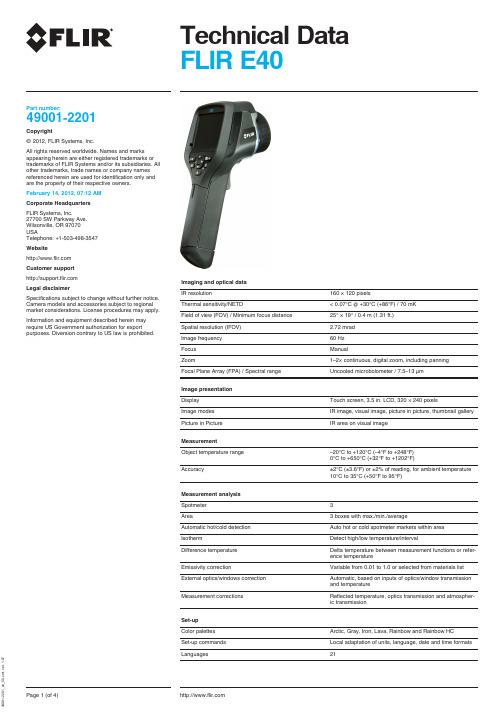
Technical Data FLIR E40Part number:49001-2201Copyright©2012,FLIR Systems,Inc.All rights reserved s and marks appearing herein are either registered trademarks or trademarks of FLIR Systems and/or its subsidiaries.All other trademarks,trade names or company names referenced herein are used for identification only and are the property of their respective owners.February 14,2012,07:12AM Corporate Headquarters FLIR Systems,Inc.27700SW Parkway Ave.Wilsonville,OR 97070USATelephone:+1-503-498-3547Website Customer support Imaging and optical data Legal disclaimerIR resolution160×120pixelsSpecifications subject to change without further notice.Camera models and accessories subject to regional Thermal sensitivity/NETD<0.07°C @+30°C (+86°F)/70mK market considerations.License procedures may apply.Field of view (FOV)/Minimum focus distance 25°×19°/0.4m (1.31ft.)Information and equipment described herein may require US Government authorization for exportSpatial resolution (IFOV) 2.72mrad purposes.Diversion contrary to US law is prohibited.Image frequency 60Hz Focus ManualZoom1–2×continuous,digital zoom,including panning Focal Plane Array (FPA)/Spectral range Uncooled microbolometer /7.5–13µmImage presentation Display Touch screen,3.5in.LCD,320×240pixelsImage modes IR image,visual image,picture in picture,thumbnail gallery Picture in Picture IR area on visual image MeasurementObject temperature range –20°C to +120°C (–4°F to +248°F)0°C to +650°C (+32°F to +1202°F)Accuracy±2°C (±3.6°F)or ±2%of reading,for ambient temperature 10°C to 35°C (+50°F to 95°F)Measurement analysis Spotmeter 3Area3boxes with max./min./averageAutomatic hot/cold detection Auto hot or cold spotmeter markers within area IsothermDetect high/low temperature/intervalDifference temperature Delta temperature between measurement functions or refer-ence temperatureEmissivity correctionVariable from 0.01to 1.0or selected from materials list External optics/windows correction Automatic,based on inputs of optics/window transmission and temperatureMeasurement correctionsReflected temperature,optics transmission and atmospher-ic transmissionSet-up Color palettes Arctic,Gray,Iron,Lava,Rainbow and Rainbow HC Set-up commandsLocal adaptation of units,language,date and time formats Languages21m l ,v e r .1.07Storage of images P/N:49001-2201Image storage Standard JPEG,including measurement data,on memory ©2012,FLIR Systems,Inc.cardAll rights reserved worldwide.Image storage modeIR/visual images;simultaneous storage of IR and visual imagesImage annotations TextText from predefined list or soft keyboard on touch screen Report generation•Separate PC software with extensive report generationVideo recording in camera Non-radiometric IR-video recording MPEG-4to memory cardVideo streamingRadiometric IR-video streaming Full dynamic to PC using USBNon-radiometric IR-video streaming Uncompressed colorized video using USB Digital camera Built-in digital camera 3.1Mpixel (2048×1536pixels),and one LED light Built-in digital lens data FOV 53°×41°Laser pointer LaserActivated by dedicated buttonLaser alignmentPosition is automatic displayed on the IR image Data communication interfaces Interfaces USB-mini,USB-A,composite video USB•USB-A:Connect external USB device•USB Mini-B:Data transfer to and from PC /Uncom-pressed colorized video Video out CompositePower system BatteryLi Ion,4hours operating timeCharging system In camera (AC adapter or 12V from a vehicle)or 2-bay chargerCharging temperature 0°C to +45°C (+32°F to +113°F)Power management Automatic shutdown and sleep mode (user selectable)Environmental data Operating temperature range –15°C to +50°C (+5°F to +122°F)Storage temperature range –40°C to +70°C (–40°F to +158°F)Humidity (operating and storage)IEC 60068-2-30/24h 95%relative humidity +25°C to +40°C (+77°F to +104°F)/2cycles EMC•EN 61000-6-2(Immunity)•EN 61000-6-3(Emission)•FCC 47CFR Part 15B (Emission)Encapsulation IP 54(IEC 60529)Bump 25g (IEC 60068-2-29)Vibration 2g (IEC 60068-2-6)SafetyPower supply:CE/PSE/EN/UL/CSA 60950-1Physical dataCamera weight,incl.battery 0.825kg (1.82lb.)Camera size (L ×W ×H)246×97×184mm (9.7×3.8×7.2in.)Tripod mountingUNC ¼"-20(adapter needed)m l ,v e r .1.07Scope of delivery P/N:49001-2201•Hard transport case©2012,FLIR Systems,Inc.•Infrared camera with lens All rights reserved worldwide.•Battery•Calibration certificate •Camera lens cap •Downloads brochure•FLIR Tools software CD-ROM •Handstrap •Memory card•Power supply,incl.multi-plugs •Printed Getting Started Guide•Printed Important Information Guide •Service &training brochure •USB cable•User documentation CD-ROM •Video cable•Warranty extension cardm l ,v e r .1.07All rights reserved worldwide.All rights reserved worldwide.All rights reserved worldwide.All rights reserved worldwide.All rights reserved worldwide.。

IMPROVE COMMUNICATION WITH CUSTOMERSCreate professional reports using FLIR Thermal Studio to better communicate problems and repairs Carry fewer tools with this convenient, all-in-one thermal camera, worklight, and pinless and pin moisture meter that meets RESNET standards GET TO THE PROBLEM FASTERVisually scan and investigate large areas for moisture, air leaks, and other building issues without opening the wallSpecifications are subject to change without notice. For the most up-to-date specs, go to S P E C I F I C A T I O N SWILSONVILLE27700 SW Parkway Ave. Wilsonville, OR 97070 USAPH: +1 866.477.3687NASHUA9 Townsend West Nashua, NH 03063 USAPH: +1 866.477.3687LATIN AMERICAAv. Antonio Bardella, 320 Sorocaba, SP 18085-852 BrasilPH: +55 15 3238 8070CANADA3430 South Service Road, Suite 103Burlington, ON L7N 3J5CanadaPH: +1 800.613.0507Equipment described herein is subject to US exportregulations and may require a license prior to export.Diversion contrary to US law is prohibited. Imagery forillustration purposes only. Specifications are subject tochange without notice. ©2021 Teledyne FLIR LLCAll rights reserved. Created 05/27/2121-0617-INSNASDAQ: TDYThermal ImagingThermal image resolution160 × 120 (19,200 pixels)Spectral response8 µm to 14 µmField of view (W × H)57° × 44°Sensitivity<150 mKObject temperaturerange0°C to 100°C (32°F to 212°F)Emissivity correction 3 pre-set and 1 custom emissivity settingImage update speedfrequency9 HzImage Modes and DisplaysThermal image palettes Iron, Rainbow, Arctic, White-hot, Black-hotMSX®Adds visual details to full resolution thermal image Image modes Thermal, Visual, MSXInternal memory8 GBImage gallery YesDisplay type QVGA (320 × 240 pixels) 2.8-in color TFT graphicaldisplayMoisture MeasurementsPin moisture range7% to 100%Pin moisture accuracy±1.5%, 7% to 30%, Reference only: 30% to 100% Pin moisture groups11 material groupsPinless moisture rangeand accuracy0 to 100; relativePinless measurementdepthMax of 19 mm (0.75 in)Measurement resolution0.1Response timepinless mode100 msResponse time pin mode 750 msGeneral InformationSaved image file format Radiometric jpgStored image capacity 15,000 ImagesDigital camera 2 MPDigital camerafield of view (FOV)83° (70.5° HFOV × 56° VFOV)Language options22Laser type Visible class 2, single laser pointer to center ofthermal imageWarranty Limited 10-Year WarrantyPower SystemContinuous run time10 hours maximumTypical usage 4 work weeksAuto power off Programmable: off, 5, 10, 20 and 30 minutesBattery Rechargeable 3.7 V nominal, 5400 mAh LiPoCertificationsCertification standards EN 61326 (EMC), EN 60825-1 Class 2 (laser),IEC61010-1Agency approvals CE, RCM, FCC Part 15B, UKCAEnvironmental and Physical DataOperating temperature0°C to 45°C (32°F to 113°F)Storage temperature-20°C to 60°C (-4°F to 140°F)Operating humidity10% to 90%Storage humidity90% relative humidity (no condensation)Drop test 2 m (6.6 ft)Weight392 g (0.7 lb)Size (L × W × H)17.7 × 8.9 × 3.6 cm (6.97 × 3.5 × 1.43 in)Shipping InformationPackaging contents FLIR MR265, FLIR MR02 Standard Moisture PinProbe, quick start guide, international USB charger,USB cable, and lanyard。

, opciones de lentes intercambiables,Cámara digital integrada de 5 MP, lámparas LED, puntero láser, botón de captura de imagen y capacidad de enfoque automático. Bloque óptico de rotación de 120ºLa orientación automáticamantiene vertical los datosde pantalla.Croquis en IR/visual:utilice la pantalla táctil paradibujar círculos, punteros,etc.en las imágenes guardadas.Especificaciones de la imagenAplicaciones55901-2302 ..........Cámara termográfica de infrarrojos (640 x 480) FLIR T620 con Wi-Fi y lente estándar de 25°55901-2303 ..........Cámara termográfica de infrarrojos (640 x 480) FLIR T620 con Wi-Fi y lente estándar de 45° 55902-2502 ..........Cámara termográfica de infrarrojos (640 x 480) FLIR T640 con Wi-Fi y lente estándar de 25°55902-2503..........Cámara termográfica de infrarrojos (640 x 480) FLIR T640 con Wi-Fi y lente estándar de 45°Mercado de empresas de servicios públicos: utilice cámaras de infrarrojos para localizar problemas o detectar puntos calientes yotros contratiempos antes de que se conviertan en averías y períodos de inactividad en la producción costosos o en incendios.Inspecciones eléctricas: con las cámaras termográficas FLIR los contratistas de servicios eléctricos pueden escanear cuadros, paneles y componentes eléctricos para conseguir una visión sin contacto de su estado. NASDAQ: FLIREl equipo descrito en este documento puede requerir la autorización del Gobierno de EE. UU. para su exportación. Quedan prohibidas las desviaciones contrarias a la ley de EE.UU. Las imágenes utilizadas tienen una función meramente informativa. Las especificaciones están sujetas a cambios sin previo aviso. ©2014 FLIR Systems, Inc. Todos los derechos reservados. 3592 (Ver. 09/13)FLIR Commercial Systems Luxemburgstraat 22321 Meer BélgicaTel.: +32 (0) 3665 5100Fax: +32 (0) 3303 5624Correoelectrónico:*************FLIR Systems AB SueciaTel.: +46 (0)8 753 25 00FLIR Systems UKTel.: +44 (0)1732 220 011FLIR Systems GmbH AlemaniaTel.: +49 (0)69 95 00 900FLIR Systems FranceTel.: +33 (0)1 60 37 55 02 FLIR Systems ItalyTel.: +39 (0)2 99 45 10 01FLIR Commercial Systems EspañaTel.: +34 91 573 48 27FLIR Systems, Middle East FZE Dubái - Emiratos Árabes Unidos Tel.: +971 4 299 6898FLIR Systems RussiaTel.: + 7 495 669 70 72ACCESORIOST197914 ........Lente IR, f=41,3 mm (15°) con estuche T197922 ........Lente IR, f=24,6 mm (25°) con estuche T197915 ........Lente IR, f=13,1 mm (45°) con estuche T198059 ........ L entes IR de aproximación, 2,9× (50 µm) conestucheT198060 ........ L entes IR de aproximación, 5,8× (100 µm) conestucheT198166 ........ L ente IR, f=88,9 mm (7°) con estuche ysoporteT198065 ........Lente IR, f=6,5 mm (80°) con estucheT198066 ........ L entes IR de aproximación, 1,5× (25 µm) conestucheT910814 ........Alimentación, incluidos varios conectores T198506 ........Paquete de batería de ión-litio, 37,7 V-29 Wh T911230ACC ..Tarjeta de memoria SDHC 4 GB 1910423 ........Cable USB Std A <-> Mini-B T198509 ........ K it adaptador para encendedor de cigarrillos,12 VCC, 1,2 m/3,9 ft.T910930ACC .Cable HDMI tipo C a DVI de 1,5 mT910891ACC ..Cable HDMI tipo C a cable HDMI tipo A 1,5 mT198625 ........Maletín de transporte rígido T198495 ........EstucheT198497 ........Ocular grandeT198498 ........Adaptador de trípode T198496 ........Lápiz ópticoT198499 ........Correa para cuello T197771ACC ..Auriculares Bluetooth T198583 ........FLIR Tools+ (solo licencia) T911093 ........Cinturón de herramientas。

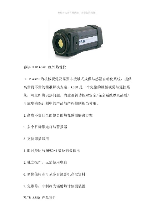
容祺FLIR A320 红外热像仪FLIR A320为机械视觉及需要非接触式成像与感温自动化系统,提供高贵而不贵的精准解决方案。
A320是一个完整的机械视觉与遥控系统,可立即辨识热问题。
内建逻辑功能对安全/保全系统以及品质/可靠度确保计划中的产品与产程控制相当使用。
1.高贵不贵且全面整合的热像感测解决方案2.多个目标聚光灯与警报器3.支持即插即用4.即时类比与MPEG-4数位影像输出5.独立操作,无需使用电脑6.多位使用者可从多台摄影机存取资料7.免维修,非制冷为辐射热计侦测装置FLIR A320 产品特性快速发现错误及早发现并解决问题可解决安全问题,减少报废与维护支出,提升产品品质,进而省下大笔支出。
A320的热成像、温度报警器、实际温度读出装置等功能,可以轻松侦测到其他方式无法侦测到的微幅温度变化。
非接触式立即温度感测功能A320的设计目的是希望为广大自动化应用领域提供精确的热成像及可重复温度感测功能。
每个热影像都是从76,800条个别像素组成,那些像素则由摄影机的内建感温电子与软体采样。
即时14位元320×240影像资料,有助于感测及控制产程,或经由摄影机的内建智能加以处理,自动产出多个独立是数位警报器。
MPEG-4压缩影像格式有助于数位影像传输。
先进热像与高热敏感度从一开始,A320就着眼于开发出精确的放射热像与可重复温度感测功能,具备先进非制冷未测辐射热计焦面阵列(FPA)侦测器,可在多个调色盘中传输清晰长波影像。
延伸连接选项多台 A320 摄影机可透过 100baseT高速乙太网络连结形成网络,并透过SNTP协定进行同步作业。
每台摄影机可分配到一个独有的IP位址,在网络上进行侦测与资料交换。
FLIR的红外线侦测软件可利用个人计算机透过网络完成摄影机控制、配置、检测作业,授权使用者也可透过 LAN/WAN 存取 A320热像及温度资料。
此外,还可利用SMTP 或 FTP 协定透过电子邮件将警告讯息传送到遥远的地点。
Feb 2007IPU 40124The IRI 4040 is an innovative thermal imager product, which offers outstanding imaging and temperature measurement performance together with the traditional IRISYS features of flexibility, ease of use, and minimal cost of ownership.IRISYS has produced an imager that is ideal for the thermographer and maintenance engineer alike; high quality images may be captured and manipulated offline or problems can be resolved on the spot. The camera comes with an industry leading 3 ½" display and delivers price and performance that are unique to IRISYS.The narrow angle 9.1° x 6.8° lens enables detection and temperature measurement of small objects over long distances. The IRI 4040 is especially suitable for use in the power utilities industries for the inspection of substation and overhead distribution and transmission lines.IRI 4040Long Range Thermal ImageraThe IRI 4040 Long RangeThermal ImagerInnovativeThermalImagingProduct DescriptionThe ergonomically designed imager houses the complete uncooled microbolometer-based camera core together with a long life Li-ion battery pack. For ease of use the image is displayed on a large 3½" colour LCD with LED backlight. Images can be captured using an MMC or SD card for recall and further analysis if required. Images can also be downloaded to a PC from the memory card for analysis, report generation and printing.OperationDesigned for self-contained use, the camera is the ideal tool for all maintenance engineers. The high capacity, field replaceable, rechargeable Li-ion battery allows continuous operation for a full working shift. The IRI 4040 is fully radiometric; temperature measurements can be made over the entire image, and hot spots can be identified by use of a trigger activated laser pointer.© 2007 InfraRed Integrated Systems Limited (IRISYS). No part of this publication may be reproduced without prior permission in writing from InfraRed Integrated Systems Limited. This document gives only a general description of the product and except where expressly provided otherwise shall form no part of any contract. IRISYS have a policy of continuous product improvement and reserve the right to change the specification of the products and descriptions in this data sheet. Prior to ordering products please check with IRISYS for current specification details.SPECIFICATIONPERFORMANCEField of view (FOV): 9.1o x 6.8o Focus: ManualMinimum Focus: 50cm (120cm for radiometry) Spectral Response: 8µm to 14µmThermal Sensitivity: 150mK (0.15°C) @21°C ambient and25°C scene temperatureImaging Range -10°C to 250°C Detector: 160x120 pixels uncooled microbolometerIMAGE STORAGENumber: Up to 1000 images on SD card supplied Medium: MMC/SD cardDISPLAY3½" colour LCD with LED backlight 4 colour palettesLASER POINTERA built in Class 2 laser is supplied to highlight the central measurement areaMEASUREMENTTemperature range: 0°C to +250°CRadiometry: Two movable temperature measurement cursors Temperature difference measurement Emissivity Correction:User selectable 0.2 to 1.0 in steps of 0.01 with reflected ambient temperature compensationAccuracy: The greater of +2o C or 2% of reading in o C.IMAGER POWER SUPPLYBattery: Lithium-ion field rechargeable, replaceable batteriesOperation time: Up to 6 hours continuous operation AC operation: AC adaptor suppliedMECHANICALHousing: Impact Resistant Plastic Dimensions: 230mm x 120mm x 135mmWeight: Less than 0.8kg including battery Mounting: Handheld & Tripod mountingIRI 4040 INCLUDESIR Camera, Battery, AC adaptor, USB Cable, usermanual and software CD, carrying case, wrist strap, SD card and SD card reader, light shade .OPTIONAL ACCESSORIESR eport writing software; desktop charger; 12V car charger; additional battery.INTERFACESUSB type BSETTINGS AND CONTROLS• On/Off soft power control • User selectable span control • User selectable level control • Auto adjust span and level• Display palettes: rainbow, ironbow, high contrast and greyscale• Laser trigger switch • Readout in °C, °F or K• Image capture, time and date • 2 x digital zoomFEATURES• Real time image and temperature measurement display• Crisp high resolution images • Large 3 ½ inch display • Simple operation• Multiple temperature measurement• Multiple image storage and retrieval at full digital resolution• Image browser with full image adjustment • Battery Charge indicator • LightweightUse, duplication or disclosure of data contained on this sheet is subject to the restrictions on the title page of this document. Whilst IRISYS endeavour to ensure that all descriptions, weights, temperatures, dimensions, and other statistics contained in this product information are correct, they are intended to give a general idea of the product only and IRISYS do not warrant their accuracy or accept liability for any reliance on them. This product may be protected by patents RE36136, RE36706, US4752694, US5286976, US5300915, US5420419, US5895233 and US5637871. All brands and product names are acknowledged and may be trademarks or registered trademarks of their respective holders.aInnovativeThermal ImagingInfraRed Integrated Systems Ltd, Park Circle, Tithe Barn WaySwan Valley, Northampton, NN4 9BG, UK Telephone: +44 (0) 1604 594200 Fax: +44 (0) 1604 594210 e-mail: ***************.uk web site: IRI 4040。
TECHNICAL NOTEIn the field of research and development (R&D) thermal imaging cameras are already an established tool for the evaluation of solar cells and panels. For these sophisticated measurements, usually high performance cameras with cooled detectors are used under controlled laboratory conditions.However, the use of thermal imaging cameras for solar panel evaluation is not restricted to the field of research. Uncooled thermal imaging cameras are currently being used more and more for solar panel quality controls before installation and regular predictive maintenance checkups after the panel has been installed. Because these affordable cameras are handheld and lightweight, they allow a very flexible use in the field.With a thermal imaging camera, potential problem areas can be detected and repaired before actual problems or failures occur. But not every thermal imaging camera is suited for solar cell inspection, and there are some rules and guidelines that needto be followed in order to perform efficient inspections and to ensure that you drawcorrect conclusions. The examples in this article are based on photovoltaic modules with crystalline solar cells; however, the rules and guidelines are also applicableto the thermographic inspection of thin-film modules, as the basic concepts of thermography are the same.PROCEDURES FOR INSPECTING SOLAR PANELS WITH THERMAL IMAGING CAMERAS During the development and production process, solar cells are triggered either electrically or by the use of flash lamps. This ensures that there is sufficient thermal contrast for accurate thermographic measurements. This method cannot be Thermal imaging cameras: a fast and reliable tool for testing solar panels.applied when testing solar panels in the field, however, so the operator must ensure that there is a sufficient energy input by the sun.To achieve sufficient thermal contrast when inspecting solar cells in the field, a solar irradiance of 500 W/m 2 or higher is needed. For the maximum result a solar irradiance of 700 W/m 2 is advisable. The solar irradiance describes the instantaneous power incident on a surface in units of kW/m 2, which can be measured with either a pyranometer (forglobal solar irradiance) or a pyrheliometer (for direct solar irradiance). It stronglydepends on location and local weather. Low outside temperatures may also increase thermal contrast.Quality assurance is of fundamental importance for solar panels. The failure-free operation of the panels is a prerequisite for efficient power generation, long life, and a high return on the investment. To ensure this failure free operation a fast, simple and reliable method to evaluate a solar panel's performance is required, both during the production process and after the panel has been installed. The use of thermal imaging cameras for solar panel evaluation offers several advantages. Anomalies can clearly be seen on a crisp thermal image and - unlike most other methods - thermal cameras can be used to scan installed solar panels during normal operation. Finally, thermal cameras also allow to scan large areas within a short time frame.Thermogram with level and span in automaticmode (above) and in manual mode (below).TECHNICAL NOTE predictive maintenance inspectionshighest when the camera is perpendicular, and decreases with an increasing angle. A viewing angle of 5–60° is a good compromise (where 0° is perpendicular).LONG DISTANCE OBSERVATIONS It is not always easy to achieve a suitable viewing angle during the measurement set-up. Using a tripod can provide a solution in most cases. In more difficult conditions it might be necessary to use mobile working platforms or even to fly over the solar cells with a helicopter. In these cases, the longer distance from the target can be advantageous, since a larger area can be seen in one pass. To ensure the quality of the thermal image, a thermal imaging camera with an image resolution of at least 320 × 240 pixels, preferably 640 × 480 pixels, should be used for these longer distances.The camera should also have an interchangeable lens, so the operator can switch to a telephoto lens for long distance observations, such as from a helicopter. It is advisable, however, to only use telephoto lenses with thermal imaging cameras that have a high image resolution. Low resolution thermal imaging cameras will be unable to pick up the small thermal details thatindicate solar panel faults in long distance measurements using a telephoto lens.LOOKING AT IT FROM A DIFFERENT PERSPECTIVE In most cases installed photovoltaic modules can also be inspected with a thermal imaging camera from the rear of amodule. This method minimizes interfering reflections from the sun and the clouds. In addition, the temperatures obtained at the back may be higher, as the cell is being measured directly and not through the glass surface.AMBIENT AND MEASUREMENT CONDITIONS When undertaking thermographic inspections, the sky should be clear since clouds reduce solar irradiance and also produce interference through reflections. Informative images can, however, be obtained even with an overcast sky, provided that the thermal imaging camera used is sufficiently sensitive. Calm conditions are desirable, since any airflow on the surface of the solar module will cause convective cooling and thus will reduce the thermal gradient. The cooler the air temperature, the higher the potential thermal contrast. Performing thermographic inspections in the early morning is an option.Another way to enhance thermal contrast is to disconnect the cells from a load, to prevent the flow of current, which allowsheating to occur through solar irradiance alone. A load is then connected, and the cells are observed in the heating phase.Under normal circumstances, however, thesystem should be inspected under standard operating conditions, namely under load. Depending on the type of cell and the kind of fault or failure, measurements under no-load or short-circuit conditions can provide additional information.MEASUREMENT ERRORSMeasurement errors arise primarily due to poor camera positioning and suboptimal ambient and measurement conditions. Typical measurement errors are caused by:• too shallow viewing angle • c hange in solar irradiance over time (due to changes in sky cover, for example)• r eflections (e.g., sun, clouds,surrounding buil d ings of greater height, measurement set-ups)• p artial shadowing (e.g., due to surrounding buildings or other structures).Thermal image made using a FLIR P660 cameraon a flight over a solar farm. (Thermogramcourtesy of Evi Müllers, IMM)In order not to draw false conclusions you need to hold the thermal imaging camera under a correct angle when inspecting solar panels.This thermal image shows large areas withelevated temperatures. Without more information, it is not obvious whether these are thermal anomalies or shadowing/reflections.Thermal image of the back of a solar module taken with a FLIR P660 camera. Its corresponding visual image is shown on the right.For more information visit or contact:FLIR Commercial Systems B.V.Charles Petitweg 214847 NW Breda - Netherlands Phone : +31 (0) 765 79 41 94Fax : +31 (0) 765 79 41 99e-mail :*************T 820228 {E N _u k }_ATECHNICAL NOTEWHAT CAN YOU SEE IN THE THERMAL IMAGEIf parts of the solar panel are hotter than others, the warm areas will show up clearly in the thermal image. Depending on the shape and location, these hot spots and areas can indicate several different faults. If an entire module is warmer thanusual that might indicate interconnection problems. If individual cells or strings of cells are showing up as a hot spot or a warmer ‘patchwork pattern’, the cause can usually be found either in defective bypass diodes, in internal short-circuits, or in a cell mismatch.Shadowing and cracks in cells show up as hot spots or polygonal patches in thethermal image. The temperature rise of a cell or of part of a cell indicates a defective cell or shadowing. Thermal images obtained under load, no-load, and short-circuit conditions should be compared. A comparison of thermal images of the front and rear faces of the module can also give valuable information. Of course, for correct identification of the failure, modules showing anomalies must also be tested electrically and inspected visually.CONCLUSIONSThe thermographic inspection of photovoltaic systems allows the fast localization of potential defects at the cell and module level as well as the detection of possible electrical interconnection problems. The inspections are carried out under normal operating conditions and do not require a system shut down.For correct and informative thermal images, certain conditions and measurement procedures should be observed:• a suitable thermal imaging camera with the right accessories should be used;• s ufficient solar irradiance is required (at least 500 W/m 2 – above 700 W/m 2 preferred);• t he viewing angle must be within the safe margins (between 5° and 60°);• s hadowing and reflections must be prevented.Thermal imaging cameras are primarily used to locate defects. Classification and assessment of the anomalies detected require a sound understanding of solar technology, knowledge of the system inspected, and additional electrical measurements. Proper documentation is, of course, a must, and should contain all inspection conditions, additional measurements, and other relevant information.Inspections with a thermal imagingcamera - starting with the quality control in the installation phase, followed by regular checkups - facilitate complete and simple system condition monitoring. This will help to maintain the solar panels' functionality and to extend their lifetime. Using thermal imaging cameras for solar panel inspections will therefore drastically improve the operating company’s return oninvestment.Table 1: List of typical module errors (Source: ZAE Bayern e.V , “Überprüfung der Qualität von Photovoltaik-Modulen mittels Infrarot-Aufnahmen” ["Quality testing in photovoltaic modules using infrared imaging”], 2007)These red spots indicate modules that are consistently hotter than the rest, indicating faulty connections.This hot spot within one solar cell indicates physical damage within the cell.This thermal image shows an example of the so-called ‘patchwork pattern’, which indicates that this panel has a defective bypass diode.。
FLIR A6750sc MWIRThermal imaging camera with FLIR cooled InSb detector HIGH SENSITIVITY, CRISP THERMAL IMAGESFLIR A6750sc incorporates a cooled FLIR Indium Antimonide (InSb) detector that operates in the 3- to 5-micron waveband. Optionally, a broadbandversion that operates in the 1-5 micron waveband is available. Both versions produce crisp thermal images of 640 x 512. Achieving a high thermal sensitivity of <20 mK, FLIR A6700sc is able to capture the finest image details.FAST INTEGRATION TIMESWorking in snapshot mode, the FLIR A6750sc is able to capture all pixels from a scene simultaneously in under 190µs for room temperature scenes. This is particularly important when monitoring fast moving objects where an uncooled thermal imaging camera would suffer from image blur. The camera supports image frame rates up to 4.1k frames per second when operating in windowing mode.STANDARD VIDEO INTERFACESUsing a standard GigE Vision ® interface to transmit full dynamic range digital video, and GenICam for camera control, the FLIR A6750sc is a true “plug and play” thermal imaging camera. Additional interfaces include a BNC analog video output. The Gigabit Ethernet and analog video are simultaneously active yet independently controlled allowing greater flexibility for recording and display purposes.CUSTOM COLD FILTERS AVAILABLECustom cold filtering options for specific spectral detection and measurement are available. Perfect for imaging through glass, measuring temperature of thin film plastics, laser profiling and detection, or optical gas imagingSOFTWAREFLIR A6750sc camera works seamlessly with FLIR ResearchIR Max software enabling intuitive viewing, recording and advanced processing of thethermal data provided by the camera. A Software Developers Kit (SDK) is optionally available.COMPATIBLE WITH 3RD PARTY SOFTWARE Control the A6750sc and capture data directly into MathWorks ® MATLAB software for custom image analysis and enhancement.KEY FEATURES• FLIR built cryo cooler and insb detector• Excellent image quality: 640 x 512 pixels • High sensitivity: <20 mK• High speed image acquisition: up to 4,1 kHz in windowing mode• Synchronization with other instruments and events • Wide choice of optics & extender ringsElectronics microscopyMotorcycle brake testingImaging Specifications NASDAQ: FLIRSpecifications are subject to change without notice©Copyright 2015, FLIR Systems, Inc. All other brand and product names are trademarks of their respective owners. The images displayed may not be representative of the actual resolution of the camera shown. Images for illustrative purposes only. (Created 04/15)PORTLANDCorporate Headquarters FLIR Systems, Inc.27700 SW Parkway Ave.Wilsonville, OR 97070USAPH: +1 866.477.3687BELGIUMFLIR Systems Trading Belgium BVBALuxemburgstraat 22321 Meer BelgiumPH: +32 (0) 3665 5100SWEDENFLIR Systems AB Antennvägen 6, PO Box 7376SE-187 66 Täby SwedenPH: +46 (0)8 753 25 00NASHUAFLIR Systems, Inc.9 Townsend West Nashua, NH 06063USAPH: +1 603.324.7611UKFLIR Systems UK 2 Kings Hill Avenue Kings HillWest Malling - Kent ME19 4AQUnited KingdomPH: +44 (0)1732 220 011On/Off switchStatus LEDsPower inCat 6 Ethernet portSyncVideo portAUX port。