OVM设备产品说明书_ZB4-500电动油泵
- 格式:pdf
- 大小:5.66 MB
- 文档页数:23
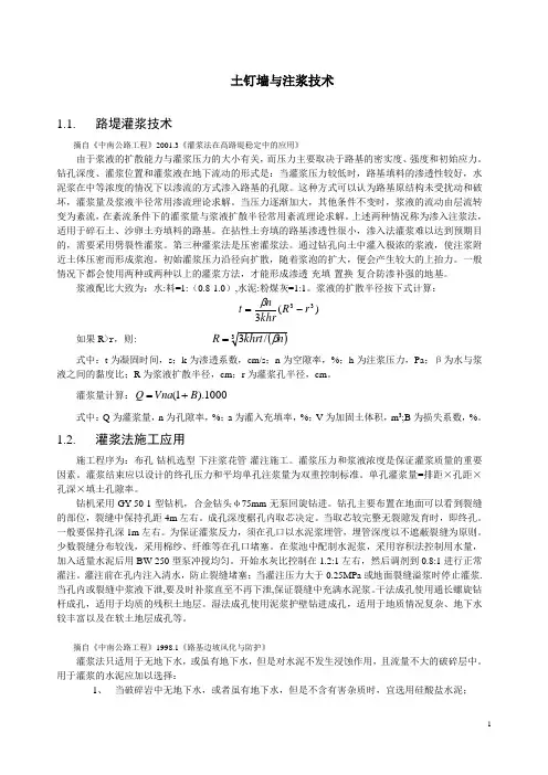
土钉墙与注浆技术1.1. 路堤灌浆技术摘自《中南公路工程》2001.3《灌浆法在高路堤稳定中的应用》由于浆液的扩散能力与灌浆压力的大小有关,而压力主要取决于路基的密实度、强度和初始应力。
钻孔深度、灌浆位置和灌浆液在地下流动的形式是:当灌浆压力较低时,路基填料的渗透性较好,水泥浆在中等浓度的情况下以渗流的方式渗入路基的孔隙。
这种方式可以认为路基原结构未受扰动和破坏,灌浆量及浆液半径常用渗流理论求解。
当压力逐渐加大,其他条件不变时,浆液的流动由层流转变为紊流,在紊流条件下的灌浆量与浆液扩散半径常用紊流理论求解。
上述两种情况称为渗入注浆法,适用于碎石土、沙卵土夯填料的路基。
在拈性土夯填的路基渗透性很小,渗入法灌浆难以达到预期目的,需要采用劈裂性灌浆。
第三种灌浆法是压密灌浆法。
通过钻孔向土中灌入极浓的浆液,使注浆附近土体压密而形成浆泡。
初始灌浆压力沿径向扩散,随着浆泡的扩大,便会产生较大的上抬力。
一般情况下都会使用两种或两种以上的灌浆方法,才能形成渗透-充填-置换-复合防渗补强的地基。
浆液配比大致为:水:料=1:(0.8-1.0),水泥:粉煤灰=1:1。
浆液的扩散半径按下式计算:)(333r R khr nt -=β 如果R >r ,则: ()3/3n khrt R β=式中:t 为凝固时间,s ;k 为渗透系数,cm/s ;n 为空隙率,%;h 为注浆压力,Pa ;β为水与浆液之间的黏度比;R 为浆液扩散半径,cm ;r 为灌浆孔半径,cm 。
灌浆量计算:1000).1(B Vna Q +=式中:Q 为灌浆量,n 为孔隙率,%;a 为灌入充填率,%;V 为加固土体积,m 3;B 为损失系数,%。
1.2. 灌浆法施工应用施工程序为:布孔-钻机选型-下注浆花管-灌注施工。
灌浆压力和浆液浓度是保证灌浆质量的重要因素。
灌浆结束应以设计的终孔压力和平均单孔注浆量为双重控制标准。
单孔灌浆量=排距×孔距×孔深×填土孔隙率。
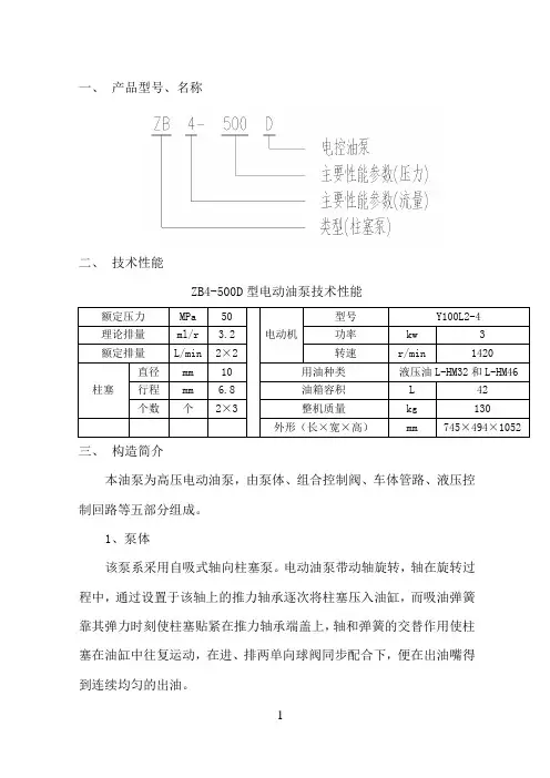
一、产品型号、名称二、技术性能ZB4-500D型电动油泵技术性能三、构造简介本油泵为高压电动油泵,由泵体、组合控制阀、车体管路、液压控制回路等五部分组成。
1、泵体该泵系采用自吸式轴向柱塞泵。
电动油泵带动轴旋转,轴在旋转过程中,通过设置于该轴上的推力轴承逐次将柱塞压入油缸,而吸油弹簧靠其弹力时刻使柱塞贴紧在推力轴承端盖上,轴和弹簧的交替作用使柱塞在油缸中往复运动,在进、排两单向球阀同步配合下,便在出油嘴得到连续均匀的出油。
该泵共有6个油缸,圆周等分排列又交错分成两条排油路,每一排油路均由三个相间120°角的油缸组成。
两条排油路单独出油,各不相扰。
本泵头系阀式配流,斜盘式轴向柱塞泵,设有5XΦ10柱塞副,公称流量为2L/min,最高压力为50MPa。
泵头结构示意图如图1。
图1 泵头构造示意图2、控制阀整组控制阀是在原ZB4-500型电动油泵控制阀基础上增加比例溢流阀PMVP4-44/24及球式电磁换向阀VZP1D22-G24而成。
工作时把与P 口(在阀块上打有钢印)连接的原ZB4-500电动油泵一侧控制阀关闭,另一侧控制阀开启,系统的压力由比例溢流阀调定,压力的高低变化与控制电流的变化有关。
千斤顶的伸缩缸通过电磁换向阀的切换来实现。
3、控制回路4、油箱小车车体采用薄板焊接结构,油在下部,主泵直接浸入油中。
泵、阀和电动油泵与翻板系固定联接,高压管采用Φ9x2.5紫铜管及Φ6高压胶管,低压管采用Φ11x0.5透明塑料管和Φ6高压胶管。
油箱采用钢板焊接,容量约为42L。
小车安装固定轮及万向轮,转向灵活,运输轻便。
5、电器开关采用磁力开关,以减少负载时的启动电流。
四、使用与保养(一)灌油本油泵采用优质矿物油,油内不含水、酸及其他杂质混合物,粘度约为2~3,根据环境温度实际情况一般可采用液压油L-HM32(冬用)或L-HM46(夏用)灌油前需经过滤,并应把油箱、泵体管路等处清洗干净,否则泥沙铁屑等脏物带入将可能发生不正常的磨损和刮伤,甚至造成事故。
预应力筋张拉施工工艺流程介绍(6)张拉平台的搭设:应在张拉端设置张拉平台,平台平面方向沿预应力束方向至少2.5m,宽度约为1.5m,平台高度应低于预应力束500mm左右,以保证张拉顺利进行。
(7)构件端头清理及钢绞线清理。
(8)动力电源及照明电源的布置:驱动油泵电源为380V,配电盘至少15A,要求电源拉至张拉平台位置。
(9)张拉班组布置及安全技术交底。
(10)工具锚、限位板、顶压器等配套设备及配套工具准备完毕。
二、张拉顺序预应力筋的张拉顺序,应考虑结构的受力特点、施工方便、操作安全等因素确定。
当框架结构的主次梁均施加预应力时,应先张拉次梁,后张拉主梁。
梁中预应力筋的张拉应左右对称进行。
三、预应力筋张拉程序首先从零加载至量测伸长值起点的初拉力(10%δcom),然后分级加载至所需的张拉力。
四、预应力筋张拉1、清理垫板及钢绞线表面的灰浆;2、安装锚板,夹片;3、千斤顶就位,千斤顶上的工具锚孔位与构件端部工作锚的孔位排列要一致,;5、工具锚夹片打紧,将夹片均匀打紧并外露一致;6、油泵供油给千斤顶张拉油缸,并随时检查伸长值与计算值的偏差。
6、张拉到规定油压后,持荷复验伸长值,合格后实施锚固7、千斤顶活塞回程;8、拆除千斤顶;9、切除多余的钢绞线;五、预应力的张拉管理1、预应力筋的张拉管理,采取应力控制,伸长校核。
实际伸长值与计算伸长值的允许偏差+10%,-5%。
如超过该值,应暂停张拉;采取措施予以调整后,方可继续张拉。
如伸长值偏小,可采取超张拉措施,但张拉力限值不得大于0.8fptk值。
2、锚固阶段张拉端预应力筋的内缩量允许值应不大于5mm。
六、张拉操作要点:1、张拉前安装锚具时必须把梁端埋件清理干净,先装好锚板后装夹片;2、组装张拉设备顺序是先装限位板,后装第二块限位板。
限位板必须和千斤顶相匹配,从而确保张拉力的作用线和预应力筋末端中心线一致;3、张拉时,要严格控制进油速度,要求缓慢、均匀、平稳;4、张拉过程中,应认真测量预应力筋的伸长值和张拉力,进行“双控”并作好记录;双控法张拉注意事项张拉注意事项(1)钢绞线张拉前应全面检查锚具、千斤顶及油泵等张拉设备的性能、型号、数量等是否附合设计和施工要求。
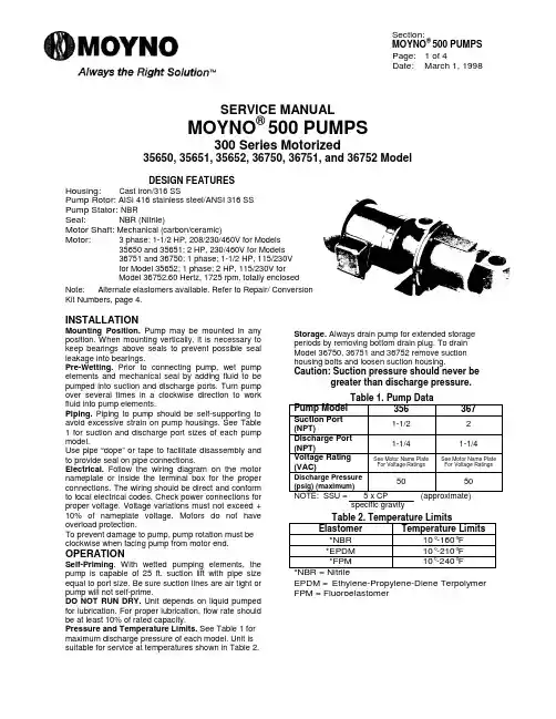
Section:MOYNO® 500 PUMPSPage: 1 of 4Date:March 1, 1998SERVICE MANUALMOYNO® 500 PUMPS300 Series Motorized35650, 35651, 35652, 36750, 36751, and 36752 ModelDESIGN FEATURESHousing:Cast iron/316 SSPump Rotor: AISI 416 stainless steel/ANSI 316 SSPump Stator: NBRSeal:NBR (Nitrile)Motor Shaft: Mechanical (carbon/ceramic)Motor: 3 phase; 1-1/2 HP, 208/230/460V for Models35650 and 35651; 2 HP, 230/460V for Models36751 and 36750; 1 phase; 1-1/2 HP, 115/230Vfor Model 35652; 1 phase; 2 HP, 115/230V forModel 36752.60 Hertz, 1725 rpm, totally enclosedNote:Alternate elastomers available. Refer to Repair/ ConversionKit Numbers, page 4.INSTALLATIONMounting Position. Pump may be mounted in any position. When mounting vertically, it is necessary to keep bearings above seals to prevent possible seal leakage into bearings.Pre-Wetting. Prior to connecting pump, wet pump elements and mechanical seal by adding fluid to be pumped into suction and discharge ports. Turn pump over several times in a clockwise direction to work fluid into pump elements.Piping. Piping to pump should be self-supporting to avoid excessive strain on pump housings. See Table 1 for suction and discharge port sizes of each pump model.Use pipe “dope” or tape to facilitate disassembly and to provide seal on pipe connections.Electrical. Follow the wiring diagram on the motor nameplate or inside the terminal box for the proper connections. The wiring should be direct and conform to local electrical codes. Check power connections for proper voltage. Voltage variations must not exceed + 10% of nameplate voltage. Motors do not have overload protection.To prevent damage to pump, pump rotation must be clockwise when facing pump from motor end. OPERATIONSelf-Priming. With wetted pumping elements, the pump is capable of 25 ft. suction lift with pipe size equal to port size. Be sure suction lines are air tight or pump will not self-prime.DO NOT RUN DRY. Unit depends on liquid pumped for lubrication. For proper lubrication, flow rate should be at least 10% of rated capacity.Pressure and Temperature Limits. See Table 1 for maximum discharge pressure of each model. Unit is suitable for service at temperatures shown in Table 2.Storage. Always drain pump for extended storage periods by removing bottom drain plug. To drainModel 36750, 36751 and 36752 remove suction housing bolts and loosen suction housing.Caution: Suction pressure should never begreater than discharge pressure.Table 1. Pump DataPump Model356367 Suction Port(NPT)1-1/22 Discharge Port(NPT)1-1/41-1/4 Voltage Rating(VAC)See Motor Name PlateFor Voltage RatingsSee Motor Name PlateFor Voltage Ratings Discharge Pressure(psig) (maximum)5050 NOTE: SSU = 5 x CP (approximate)specific gravityTable 2. Temperature LimitsElastomer Temperature Limits *NBR10°-160°F*EPDM10°-210°F*FPM10°-240°F*NBR = NitrileEPDM = Ethylene-Propylene-Diene Terpolymer FPM = FluoroelastomerTROUBLE SHOOTINGWARNING:Before making adjustments,disconnect power source andthoroughly bleed pressure fromsystem. Failure to do so could resultin electric shock or serious bodilyharm.Failure To Pump.1.Motor will not start: Check power supply. Voltagemust be ± 10% of nameplate rating when motor is in locked rotor condition.2.Motor runs and thermally kicks out: Check forexcessive pressure. Increase ventilation to motor.Do not use less than #14 wire size.3.Stator torn; possible excessive pressure: Replacestator, check pressure at discharge port.4. Flexible joint broken; possible excessive pressure:Replace joint, check pressure at discharge port. 5.Wrong rotation: Rotation must be clockwise whenfacing pump from motor end. Reverse the connections of any two line leads to the motor. 6.Excessive suction lift or vacuum.Pump Overloads.1.Excessive discharge pressure: Check pressure atdischarge port for maximum ratings given in Table 2.Fluid viscosity too high: Limit fluid viscosity to 100CP or 500 SSU.Noisy Operation.1.Excessive suction lift or vacuum: Maximum suctionlift is 25 feet for water.2.Suction line too small: Check pipe size. Be surelines are free from obstructions.3.Pump cavitates: Pump speed is 1725 rpm.Viscosity of fluid should not exceed 100 CP or 500 SSU.4.Flexible joint worn: Replace joint. Check pressureat discharge port.5.Insufficient mounting: Mount to be secure to a firmbase. Vibration induced noise can be reduced by using mount pads and short sections of hose on suction and discharge ports.Seal Leakage.1.Leakage at startup: If leakage is slight, allow pumpto run several hours to let faces run in.2.Persistent seal leakage: Faces may be crackedfrom freezing or thermal shock. Replace seal. Pump Will Not Prime.1.Air leak on suction side: Check pipe connections.PUMP DISASSEMBLYWARNING:Before disassembling pump,disconnect power source andthoroughly bleed pressure fromsystem. Failure to do so could resultin electric shock or serious bodilyharm.1.Disconnect power source.2.Remove suction and discharge piping.3.Remove screws (112) holding suction housing (2)to discharge housing (1). Remove suction housing(2) and stator (21).4.Rotor (22) can be detached from flexible joint (24)by using a punch to remove rotor pin (45). Support joint when removing pin.5.Flexible joint (24) can be removed from motorshaft by using a punch through the discharge port to remove shaft pin (46).6.Carefully slide mechanical seal (69) off motorshaft.7.Remove discharge housing (1) from motor (70) byremoving screws (112A and 112C) and washers (215).8.Carefully pry seal seat out of discharge housing(1). If any part of mechanical seal (69) is worn orbroken, the complete assembly should be replaced. Seal components are matched parts and not interchangeable.9.Remove slinger ring (77).PUMP ASSEMBLY1.Replace slinger ring (77).2.Attach discharge housing (1) to motor (70) usinglock washers (215) and body screws (112A).3.Install mechanical seal (69) using the followingprocedures:a.Clean and oil sealing faces using light oil (notgrease).Caution:Do not use oil on EPDM parts.Substitute glycerin or soap and water.b.Oil the outer surface of seal seat, and pushassembly over motor shaft into the bore of thedischarge housing (1) seating it firmly andsquarely.c.After cleaning and oiling the shaft, slide theseal body along the shaft until it meets the sealseat.d.Install seal spring and spring retainer on shaft.4.On Model 367, position seal spacer (69A) onmotor shaft with slots away from seal (69).5.Pin flexible joint (24) to motor shaft with shaft pin(46) using a punch through the discharge port. 6.Pin rotor (22) to flexible joint using rotor pin (45).Support joint while installing pin.7.Slide stator (21) on rotor (22) carefully locatingstator flange in housing groove.8.Secure stator (21) and suction housing (2) todischarge housing (1) using screws (112).9.Proceed as in installation instructions.Page 2Page 3PARTS LISTPump Model Numbers Item No.Description 3565035651356523675036751367521Discharge Housing 350-0632-007350-0632-000350-0632-007340-0951-007340-0951-000340-0951-0072Suction Housing 350-0489-000350-0280-000350-0489-000350-0302-007350-0302-000350-0302-007*21Stator 340-3505-120340-3506-120*22Rotor 320-6392-015320-6392-000320-4431-000330-3077-000330-2042-000330-3077-00024Flexible Joint 320-1618-000320-1749-000*45Rotor Pin 320-4069-003320-4439-002*46Motor Pin 320-4069-005320-4439-001*69Mechanical Seal 320-3945-000320-1750-00069A Seal Spacer 320-1737-00070Motor 330-7845-003330-7845-000330-8054-002330-2802-004300-2802-001330-8053-00472Motor Support 320-4446-00077Slinger Ring 320-6385-000103Nuts (2 req.)614-0010-111 (3/8-16)112Screw, Hex Hd 619-1530-161 (3/8-16 x 1) (4 req.)619-1530-161 (3/8-16 x 1) (6 req.)112A Screw, Hex Hd (4 req.)619-1530-161 (3/8-16 x 1)619-1550-161 (1/2-13 x 1)112B Screw, Hex Hd (2 req.)320-6918-000 (3/8-16 x 1-3/4)215Lock Washer 623-0010-411 (3/8) (4 req.)623-0010-411 (3/8) (6 req.)215A Lock Washer (4 req.)623-0010-411 (3/8)623-0010-431 (1/2)261Pipe Plug610-0120-011 (1/8 NPT)* Recommended spare partsREPAIR/CONVERSION KIT NUMBERS (For cast iron pumps only)Model 35651Model 36751Item No Description NBR EPDMFPMNBR EPDMFPM–Kit No.311-9123-000311-9125-000311-9126-000311-9060-000311-9036-000311-9124-00021• Stator 340-3505-120340-3505-320340-3505-520340-3506-120340-3506-320340-3506-52024• Joint 320-1618-000320-6508-000320-6509-000320-1749-000320-6378-000320-6515-00069• Seal 320-3945-000320-6380-000320-6510-000320-1750-000320-6390-000320-6517-00046• Pin (Motor)320-4069-005320-4439-00145• Pin (Rotor)320-4069-003320-4439-002*NBR = NitrileEPDM = Ethylene-Propylne-Diene Terpolymer FPM = FluoroelastomerABRASION RESISTANT SEALSModelsElastomer 356367NBR 320-6505-000320-6511-000EPDM 320-6506-000320-6512-000FPM320-6507-000320-6513-000© 1999 by Moyno, Inc.® Moyno is a registered trademark of Moyno Inc.Printed in U.S.A .Page 4。
预应力张拉用锚固体系的应用分析抚顺建设集团公司王焕军李国杰混凝土可用先张法、后张法或后张自锚法预加应力。
(一)安装张拉系统1)按要求编束、穿束;2)安装:①锚板②夹片③限位板④千斤顶⑤工具锚(二)张拉1)向张拉缸加油至设计值;2)测量伸长值;3)做好张拉记录。
(三)锚固1)打开高压油泵截止阀,张拉缸油压缓慢降至零;2)活塞回程。
(四)封端1)卸下工具锚、千斤顶、限位板;2)灌浆;3)切除多余钢绞线,封锚;4)用混凝土将端部封平。
1-锚板;2-夹片;3-限位板;图1 张拉工艺过程示意4-千斤顶;5-工具锚板;6-工具夹片;7-钢绞线预应力张拉用锚固体系及张拉装置有XM、QM、HVM、CQXM、OVM、STM、AM等型号,以下逐一介绍HVM型。
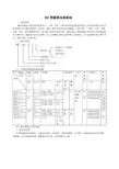
二、HVM锚固体系及张拉装置的种类及特点(一)锚固体系HVM锚固体系由张拉端锚具(HVM锚具、BM扁锚、HM锚具)、固定端锚具(H型、P型)、连接器(HVML)和波纹管组成。
按钢绞线的直径可分为HVM15、HVM13、BM15、BM13、HM15、HM13型锚具,该锚具体系具有如下优点:●应用范围广,可锚固标准强度为2000MPa及其以下级别的Φ12.7、Φ12.9、Φ15.24、Φ15.7mm钢绞线。
●可选择范围广,HVM锚固体系适用于钢绞线根数为1至55根;在此基础上还可增加钢绞线根数,以满足设计要求。
●具有良好的放张自锚性能,夹片跟进平齐,夹持性能稳定,施工操作简便。
●锚固效率系数高,锚固性能稳定、可靠。
1、锚具HVM锚具分为张拉端锚具和固定端锚具。
张拉端锚具分为圆型锚具、BM型扁锚、HM型环锚,固定端锚具分为H型压花锚、P型挤压锚。
1.1 HVM型张拉端锚固体系HVM多根数钢绞线张拉端锚固体系包括:HVM13、HVM15和HVM18圆形锚具,用于扁平结构的BM扁形锚具;用于环状应力结构的HM环形锚具。
HVM圆形锚具由夹片螺旋筋、锚板、锚垫板以及四部分组成。

Rev. DCONTENTS 50HzPage- SPECIFICATIONS200SELECTION CHART201TYPE KEY AND CURVE SPECIFICATIONS203PERFORMANCE CURVE MMD4 32-250205 PERFORMANCE CURVE MMD4 40-250206PERFORMANCE CURVE MMD4 50-250207PERFORMANCE CURVE MMD4 65-250208PERFORMANCE CURVE MMD4 80-160209PERFORMANCE CURVE MMD4 80-200210PERFORMANCE CURVE MMD4 80-250211PERFORMANCE CURVE MMD4 100-200212PERFORMANCE CURVE MMD4 100-250223PERFORMANCE CURVE MMD4 125-200214PERFORMANCE CURVE MMD4 125-250215PERFORMANCE CURVE MMD4 150-200216PERFORMANCE CURVE MMD4 200-250217- CONSTRUCTIONS300SECTIONAL VIEW300MECHANICAL SEAL 302- DIMENSIONS AND WEIGHT400PUMP 400- TECNICAL DATA500MOTOR DATA500NOISE DATA 501100Rev. DSELECTION CHART 50Hz 200Rev. DSELECTION CHART 50HzMMD 4 Poles: 32, 40, 50 Version201Rev. DSELECTION CHART 50HzMMD 4 Poles: 65, 80 VersionMMD 4 Poles: 100, 125, 150, 200 Version202Rev. DTYPE KEY AND CURVE SPECIFICATIONS 50Hz TYPE KEY:H P 1,5H P 2H P 3H P 4H P 5,5H P 7,5H P 10H P 15H P 20H P 25H P 30203Rev. DTYPE KEY AND CURVE SPECIFICATIONS 50Hz PERFORMANCE CURVE SPECIFICATIONS The specifications below qualify the curves shown on the following pages.Tolerances according to ISO 9906 Annex AThe curves refer to effective speed of asynchronous motors at 50 HzMeasurements were carried out with clean water at 20°C of temperature and with a kinematic viscosityof ν = 1 mm 2/s (1 cSt)The NPSH curve is an average curve obtained in the same conditions of performance curves.The continuous curves indicate the recommended working range. The dotted curve is only a guide.In order to avoid the risk of over-heating, the pumps should not be used at a flow rate below 10% of best efficiency point.Symbols explanation:Q =volume flow rateH =total headP 2=pump power input (shaft power)η=pump efficiencyNPSH =net positive suction head required by the pumpMEI =minimum efficiency indexThe minimun efficiency index (MEI) is a measure of the quality of a pump size in respect to its mean efficiency. The minimum efficiency index is based on the hydraulic efficiency and on the head at the best efficiency point.The efficiency of a pump with trimmed impeller is usually lower than that of a pump with the full impeller diameter. The trimming of the impeller will adapt the pump to a fixed duty point, leading to reduced energy consumption. The minimum efficiency index (MEI) is based on the full impeller diameter.The operation of these water pumps with variabile duty points may be more efficient end economic when controlled, for example, by the use of a variable speed drive that matches the pump duty to the system.204Rev. DPERFORMANCE CURVE 50HzMMD4 32-250/1.1 (1.1 kW) MEI > 0.40MMD4 32-250/1.5 (1.5 kW) MEI > 0.40Rotation speed ≈ 1400 min -1Test standard: ISO 9906 – Annex A205Rev. DPERFORMANCE CURVE 50HzMMD4 40-250/1.5 (1.5 kW) MEI > 0.40MMD4 40-250/2.2 (2.2 kW) MEI > 0.40Rotation speed ≈ 1400 minTest standard: ISO 9906 – Annex A206Rev. DPERFORMANCE CURVE 50HzMMD4 50-250/2.2 (2.2 kW) MEI > 0.40MMD4 50-250/3.0 (3.0 kW) MEI > 0.40Rotation speed ≈ 1400 minTest standard: ISO 9906 – Annex A207Rev. DPERFORMANCE CURVE50HzMMD4 65-250/4.0 (4.0 kW) MEI > 0.40MMD4 65-250/5.5 (5.5 kW) MEI > 0.40Rotation speed ≈ 1400 min Test standard: ISO 9906 – Annex A208Rev. DPERFORMANCE CURVE50HzMMD4 80-160/1.5 (1.5 kW) MEI > 0.40MMD4 80-160/2.2 (2.2 kW) MEI > 0.40Rotation speed ≈ 1400 min Test standard: ISO 9906 – Annex A209Rev. DPERFORMANCE CURVE50HzMMD4 80-200/3.0 (3.0 kW) MEI > 0.40MMD4 80-200/4.0 (4.0 kW) MEI > 0.40Rotation speed ≈ 1400 min Test standard: ISO 9906 – Annex A210Rev. DPERFORMANCE CURVE50HzMMD4 80-250/5.5 (5.5 kW) MEI > 0.40MMD4 80-250/7.5 (7.5 kW) MEI > 0.40Rotation speed ≈ 1400 min Test standard: ISO 9906 – Annex A211Rev. DPERFORMANCE CURVE50HzMMD4 100-200/4.0 (4.0 kW) MEI > 0.40MMD4 100-200/5.5 (5.5 kW) MEI > 0.40Rotation speed ≈ 1400 min Test standard: ISO 9906 – Annex A212Rev. DPERFORMANCE CURVE50HzMMD4 100-250/7.5 (7.5 kW) MEI > 0.40MMD4 100-250/11 (11 kW) MEI > 0.40Rotation speed ≈ 1400 min Test standard: ISO 9906 – Annex A213Rev. DPERFORMANCE CURVE50HzMMD4 125-200/5.5 (5.5 kW) MEI > 0.40MMD4 125-200/7.5R (7.5R kW) MEI > 0.40MMD4 125-200/7.5 (7.5 kW) MEI > 0.40 MMD4 125-200/11 (11 kW) MEI > 0.40.Rotation speed ≈ 1400 min Test standard: ISO 9906 – Annex A214Rev. DPERFORMANCE CURVE50HzMMD4 125-250/11 (11 kW) MEI > 0.40MMD4 125-250/15 (15 kW) MEI > 0.40Rotation speed ≈ 1400 min Test standard: ISO 9906 – Annex A215Rev. DPERFORMANCE CURVE50HzMMD4 150-200/7.5 (7.5 kW) MEI > 0.40MMD4 150-200/11R (11R kW) MEI > 0.40MMD4 150-200/11(11kW) MEI > 0.40MMD4 150-200/15 (15 kW) MEI > 0.40Rotation speed ≈ 1400 minTest standard: ISO 9906 – Annex A216Rev. DPERFORMANCE CURVE50HzMMD4 200-250/18.5R (18.5 kW) MEI > 0.40MMD4 200-250/18.5 (18.5 kW) MEI > 0.40MMD4 200-250/22R (22 kW) MEI > 0.40MMD4 200-250/22 (22 kW) MEI > 0.40Rotation speed ≈ 1400 min Test standard: ISO 9906 – Annex A217SECTIONAL VIEW DRAWINGUP TO MEC 160300SECTIONAL VIEW DRAWINGMEC 180 AND MORE POWERFUL301MECHANICAL SEAL302Rev. DDIMENSIONS AND WEIGHT50HzPUMP MMD4 32-40-50-65 VERSION400Rev. DDIMENSIONS AND WEIGHT50HzMMD4 80-100-125-150-200401Rev. DTECHNICAL DATA50HzMOTOR DATA500Rev. DTECHNICAL DATA50HzNOISE DATA501。

潜油电泵系统Electric Submersible Pump System目录企业简介企业资质获得的荣誉、专利生产设备潜油电泵系统介绍生产产品介绍◆潜油电机◆引接电缆◆密封保护器◆吸入口及处理器◆潜油泵◆接线盒◆变压器◆控制柜企业简介重庆虎溪电机工业有限责任公司是中国兵器装备集团所属的国有独资企业,是研制和生产特种电机、微特电机电器的专业企业,同时又是一家从事人工举升采油装备开发和制造的国家大型二类企业,是集团公司生产现场管理先进和安全级企业。
拥有中国中石油、中石化、中海油三大石油公司的一级入网证,是中国石油天然气设备出口网络成员。
公司从1984年开始从事潜油电泵的研制开发,是国家确定的潜油电泵三个定点生产厂家之一。
拥有零部件加工、环氧浇灌工艺、产品装配和出厂试验等生产制造能力,拥有自主设计、理化分析、型式试验和特种试验的科研开发能力。
公司自主研制的QYDB系列潜油电泵采油系统能够满足陆地、海上油田各种井况的采油要求,能够根据用户提出的特殊要求进行人工举升采油装备的研制、生产、安装以及技术咨询、培训、援建等技术服务。
针对不同的油井井况,企业可以为用户研发生产防砂耐磨、防腐耐高温、大排量、超高温等特殊潜油电泵。
同时,该系统还用于页岩气、天然气及盐井。
在“实现顾客愿望、高效转换能量、快速纠正不当”的质量理念指导下,形成了完善的质量管理体系。
先后通过了挪威船级社(DNV)ISO9001-2000质量管理体系认证、中国新时代认证中心GJB9001A-2001质量管理体系认证,是国家二级计量单位。
拥有计量鉴定、材料分析、在线检测等质量保证能力,潜油电泵机组产品严格执行GB/T 16750-2008国家标准。
虎溪潜油电泵产品被广泛用于大庆、胜利、辽河、中原、渤海、大港、河南、江汉、南海西部、塔里木、塔西南、吐哈、新星、青海等各大油田及四川的盐井、气井,此外还出口到美国、俄罗斯、阿塞拜疆、叙利亚等国家和地区。
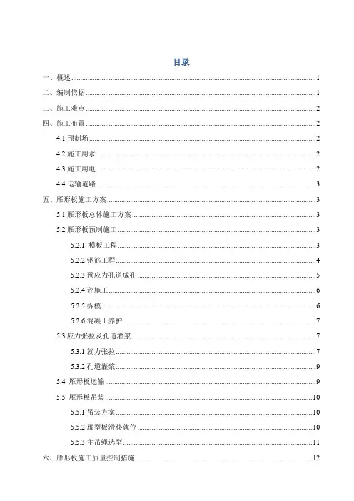
目录一、概述 (1)二、编制依据 (1)三、施工难点 (2)四、施工布置 (2)4.1 预制场 (2)4.2 施工用水 (2)4.3 施工用电 (2)4.4 运输道路 (3)五、雁形板施工方案 (3)5.1 雁形板总体施工方案 (3)5.2 雁形板预制施工 (3)5.2.1 模板工程 (3)5.2.2 钢筋工程 (4)5.2.3 预应力孔道成孔 (5)5.2.4 砼施工 (6)5.2.5 拆模 (6)5.2.6 混凝土养护 (7)5.3应力张拉及孔道灌浆 (7)5.3.1 就力张拉 (7)5.3.2 孔道灌浆 (9)5.4 雁形板运输 (9)5.5 雁形板吊装 (10)5.5.1 吊装方案 (10)5.5.2 雁型板滑移就位 (10)5.5.3 主吊绳选型 (11)六、雁形板施工质量控制措施 (12)七、施工进度计划 (13)八、资源配置 (13)8.1 人员配置 (13)8.2 设备配置 (13)厂房屋面预应力砼雁形板施工方案一、概述由于该项目的特殊性,设计院提供雁形板荷载参数,由厂家负责设计雁形板结构详略、施工,雁形板设计图见附图。
二、编制依据2、GB 50010—2002《混凝土结构设计规范》3、《后张预应力混凝土雁形板》图集说明4、GB 50204-2002《混凝土结构工程施工质量验收规范》5、JBJ/T21-93 《V型折板屋盖设计与施工规程》6、《建筑施工手册》第三版7、GB 50164-92《混凝土质量控制标准》8、GBJ 301-88《建筑工程质量检验评定标准》9、GB50109—3《建筑工程施工现场安全用电规范》10、设计图纸《雁形板屋盖结构方案》三、施工难点1)雁形板为薄壁构件,浇筑混凝土时、板面混凝土厚度及板面上层横筋位置较难控制。
2)构件表面积大,板面混凝土收缩开裂较难控制。
3)预制场地位于距离安装现场2.8km的碳化硅厂内,预制场地到安装现场弯急坡陡,最长能行驶18m拖车,而雁形板长度为24m,宽度3m,且为薄壁构件,运输难度大,运输过程中易损坏。
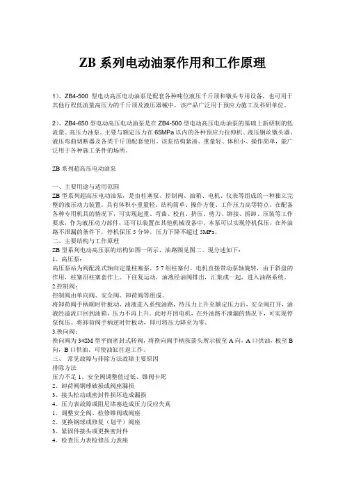
ZB系列电动油泵作用和工作原理1)、ZB4-500型电动高压电动油泵是配套各种吨位液压千斤顶和镦头专用设备,也可用于其他行程低流量高压力的千斤顶及液压器械中,该产品广泛用于预应力施工及科研单位。
2)、ZB4-650型电动高压电动油泵是在ZB4-500型电动高压电动油泵的基础上新研制的低流量、高压力油泵。
主要与额定压力在65MPa以内的各种预应力拉伸机、液压钢丝镦头器、液压弯曲切断器及各类千斤顶配套使用。
该泵结构紧凑、重量轻、体积小、操作简单,能广泛用于各种施工条件的场所。
ZB系列超高压电动油泵一、主要用途与适用范围ZB型系列超高压电动油泵,是由柱塞泵、控制阀、油箱、电机、仪表等组成的一种独立完整的液压动力装置。
具有体积小重量轻、结构简单、操作方便、工作压力高等特点。
在配备各种专用机具的情况下,可实现起重、弯曲、校直、挤压、剪刀、铆接、拆卸、压装等工作要求,作为液压动力部件,还可以装置在其他机械设备中。
本泵可以实现停机保压,在外油路不泄漏的条件下,停机保压5分钟,压力下降不超过5MPa。
二、主要结构与工作原理ZB型系列电动高压泵的结构如图一所示,油路图见图二。
现分述如下:1、高压泵:高压泵站为阀配流式轴向定量柱塞泵,5-7组柱塞付。
电机直接带动泵轴旋转,由于斜盘的作用,柱塞沿柱塞套作上、下往复运动,油液经油阀排出,汇集成一起,进入油路系统。
2.控制阀:控制阀由单向阀、安全阀、卸荷阀等组成。
将卸荷阀手柄顺时针板动,油液进入系统油路,待压力上升至额定压力后,安全阀打开,油液经溢流口回到油箱,压力不再上升。
此时开闭电机,在外油路不泄漏的情况下,可实现停泵保压。
将卸荷阀手柄逆时针板动,即可将压力降至为零。
3.换向阀:换向阀为34SM型平面密封式转阀,将换向阀手柄按箭头所示板至A向,A口供油,板至B 向,B口供油。
可使油缸往返工作。
三、常见故障与排除方法故障主要原因排除方法压力不足1、安全阀调整值过低、锥阀卡死2、卸荷阀钢球破损或阀座漏损3、接头松动或密封件损坏造成漏损4、压力表故障或阻尼堵塞造成压力反应失真1、调整安全阀、检修锥阀或阀座2、更换钢球或修复(划平)阀座3、紧固件接头或更换密封件4、检查压力表检修压力表座流量不足1、柱塞磨损间隙过大、柱塞或弹簧折断2、各处漏损造成流量不足3、油温过低造成吸油困难,油温过高造成容积效率下降4、液位过低、油泵吸空1、更换柱塞或弹簧2、紧固接头更换密封件3、控制油温在20~70℃之间4、加油型号:ZB4-500四、还不懂请联系:李先生联系电话:技术参数图事物展示实验室专用高压电动油泵五、使用维护注意事项1、本泵的工作介质为YC-N46D液压油,也可用32号机械油代替,但不准随意换用其他牌号的油液。
BZ 型超高压油泵站一、适用范围BZ 型超高压油泵站是以超高压、小型、安全、效率高等为特点的油压泵站,在需要以油压为动力的各种作业中都可以得到广泛应用。
例如:配以相应的机具和装置,可进行推广、拉伸、扩张、夹紧、弯曲、顶升、挤压等基本作业,也可进行送变电导线压接、钢筋压接、钢筋混凝土桩压桩以及桩基测试等工程作业。
油泵站内设有安全阀(注:125MPa 泵站无安全阀)、溢流阀、三位四通换向阀、操作灵活、使用方便、安全可靠。
二、型号说明:电动机D (可省略) 原动机 汽油机Q 风动马达F 改型编号 (a,b,c......) 流量1/min额定工作压力MPa 泵站 四、液压系统与工作原理:1、液压系统图BZ 型超高液压油泵站,主要由电动机(汽油机)、轴向柱塞泵、安全阀(125MPa 泵站无安全阀)、溢流阀、三位四通换向阀、油箱等组合而成。
液压系统见下图:2、工作原理:本泵站是将电能(或机械能)转变成液压能的装置,是供分离式千斤顶或其他液压机具进行作业的液压动力源。
其工作原理是:电动机(汽油机)带动压轴旋转,由于压轴的倾斜面,使与其压盘接触的柱塞产生轴向移动,柱塞油腔容积发生变化,达到吸油、压油之目的。
液压油通过三位四通换向阀将压力油输出,通过装有快换接头的两根高压软管(均可作进出油管)与分离式千斤顶或其他液压机具连接,实现顶升、下降或其他作业要求。
五、操作方法与维护1、首先由装有快换接头的高压软管将油泵站与分离式千斤顶或其他液压机具连接牢固,然后将溢流阀处于开启状态(逆时针旋松),同时将换向阀手柄盖箭头置于中间位置(见图一、图二)。
2、启动电动机(或汽油机)(电动机正反转均可),油泵站运转正常达到工作状态后,将换向阀手柄盖箭头旋转到任一管接头出口位置上,然后顺时针旋转溢流阀上的调压螺帽进行压力调节(注:当千斤顶或其他液压机具在运动时调压,压力不会升高),此时油泵站将工作油经对应的出口处输出,若接头出口软管与千斤顶上的“下腔”连接,则千斤顶上升;欲使千斤顶下降,则将换向阀手柄盖箭头方向指向另一管接头出口位置,改变工作油的输出方向,千斤顶则达到回程目的。
常山江特大桥跨320国道设计采用一联32m+48m+32m连续箱梁,采用满堂支架现浇施工,中孔设置门洞支架,以保证车辆通行。
满堂支架法施工连续梁,施工前,应设计支架布置,根据支架布置对支架基础进行加固处理,机械碾压,浇注混凝土基础,搭设支架,支架顶面搭设平台。
施工平台施工完成后,对支架进行预压,预压荷载为结构重及施工荷载的1.2倍。
并待非弹性变形消除后,方能进行箱梁混凝土的浇筑。
严格控制混凝土的入模温度在10~30℃,灌注时模板温度控制在5~35℃。
为防止梁体产生早期裂纹,在混凝土强度达到设计强度的50%~60%时拆除内模,外模只拆不移的情况下进行带模预张拉。
两侧腹板对称张拉,四顶同步进行。
在压浆材料中掺入高性能无收缩防腐灌浆剂,并采用真空辅助压浆工艺,选用连续式压浆泵,在出浆口设置三通以检验进浆口和出浆口浆体浓度是否一致。
具体工艺流程见“支架法现浇连续箱梁施工工艺框图”,说明如下:一、结构介绍新建衢常铁路常山江特大桥跨越320国道和常山江,跨越320国道是以一联32+48+32m的弯连续箱梁,与国道斜交,角度为34度。
该联弯连续箱梁全长113米(含两侧梁端至边支座中心各0.5米),位于曲线半径为2500m,纵坡为+5.5‰,设计时速160km/h的单线一级铁路线上。
道碴桥面,道碴槽宽度为4.2m,两侧人行道宽各1.4米,轨底到梁顶0.6米。
箱梁采用C50混凝土,挡碴槽采用C30混凝土,管道压浆采用M50水泥浆,封端采用C50微膨胀混凝土;钢绞线采用低松弛高强预应力钢绞线,预应力管道采用金属波纹管成孔,锚具采用OVM系列锚具。
全联梁等高为3.4米,箱梁横截面为单箱单室直腹板,顶宽7.0m,底宽4.0m,箱梁顶板厚0.32m,中支点和端支点处局部加厚至0.6m,腹板厚0.36m~0.80m,底板厚0.3m~0.6m,箱梁悬臂板端部厚0.2m,根部厚0.6米,全梁共设4道横隔板,其中在中支点处设置厚1.2m的横隔板,梁端支座处设置厚1.1m的端横隔板。
2020 年 10 月传统作动系统的高出力、节能、紧凑型替代解决方案WHAT MOVES YOUR WORLD本产品样本用于为具有一定专业知识的客户提供信息和参数。
为确保获得系统功能和系统的安全性,请对照此样本仔细查看产品的适用性。
文中所述产品如有任何更改,恕不另行通知。
如果有任何疑问,请与穆格公司联系。
Moog 是穆格公司及其子公司的注册商标。
除非另有说明,文中出现的所有商标均为穆格及其子公司所有。
有关完整免责声明,请访问 /literature/disclaimers 。
有关最新消息,请访问 /industrial 或与您当地穆格办公室联系。
简介电动伺服泵控系统 (EAS) 3.................................................................2............................................................................................................技术概述4...................................................................................................技术数据模块化 EAS 系统的供货范围 5........................................................5..................................................................................................模块:基础阀块 +EPU 6模块:高速阀块 8........................................................................................................................................................液压系统 10..................................................................................................模块:小型增压液压动力单元 (HPU) 11......................................电动伺服泵控单元 (EPU)12................................................................电力电子装置 13........................................................................................模块:运动控制 14...................................................................................背景 15............................................................................................................关于穆格 15..................................................................................................哪里需要最高水平的运动控制性能和设计灵活性,哪里就能看到穆格技术。
Electric Pumps Instruction ManualMODELS: PEM0501T, PEM1002T, PEM1503T, PEM1505T, PEM3005T PEWM0501T, PEWM1002T, PEWM1503T, PEWM1505T & PEWM3005TSFA Companies 10939 N. Pomona Ave. Kansas City, MO 64153Tel: 888-332-6419 - Fax: 816-891-6599E-mail:******************************:PEM0501T-M1_112014Model PEM0501TModel PEWM1002T, PEWM1503T & PEWM3005TModel PEM1002T, PEM1503T & PEM3005TModel PEWM0501T Maximum Operating Pressure 10,000 PSI (for double acting applications only)This is the safety alert symbol. It is used to alert you to potential personal injury hazards. Obey all safety messages that follow this symbol to avoid possible injury or death.SAFETY AND GENERAL INFORMATIONSave these instructions. For your safety, read and understand the information contained within. The owner and operator shall have an understanding of this product and safe operating procedures before attempting to use this product. Instructions and safety information shall be conveyed in operator's native language before use of this product is authorized. Make certain that the operator thoroughly understands the inherent dangers associated with the use and misuse of the product. If any doubt exists as to the safe and proper use of this product as outlined in this factory authorized manual, remove from service immediately. Inspect before each use. It is recommended that, prior to each use, an inspection be done by qualified personnel and that any missing or damaged parts, decals, warning / safety labels or signs be replaced with factory authorized replacement parts only. Any pump that appears to be damaged in any way, is worn, leaking or operates abnormally shall be removed from service immediately until such time as repairs can be made. Any pump that has been subjected to a shock load (a load dropped suddenly, causing the system pressure to exceed 10,000 PSI), shall be removed from service immediately until checked by qualified personnel. Owners and operators of this equipment shall be aware that the use and subsequent repair of this equipment does require special training and knowledge.PRODUCT DESCRIPTIONThis Pump is engineered to meet most industrial standards for Performance and Safety. Its allows quick displacement of hydraulic fluid under no load conditions and easy pumping in loaded conditions. This electric hydraulic pump supplies compressed hydraulic fluid to compatible double acting applications ONLY. Such applications include rams, presses, spreaders, compactors and crimping machines, anywhere that 10,000 PSI of double acting fluid pressure is needed. Special skill, knowledge and training may be required for a specific task and the product may not be suitable for all the jobs described above. Unsuitable applications would include applications that call for a device to move, level or support persons, animals, hazardous materials, mobile homes/ dwellings in general, mirrors and/or plate glass, and/or to connect/secure hatches, components, etc. between bulkheads. The user must make the decision regarding suitability of the product for any given task and assume the responsibility of safety for himself/herself and others in the work area.Figure 2 - Typical 4-way 3-position PEWM series ElectricPump Components (PEWM1002T shown)Remote ON/Oil Out-Figure 1 - Typical 4-way 3-position PEM se-ries Electric Pump Components(PEM1002T shown)ControlOil Out-SPECIFICATIONSModel Number (for use w/ double actingcylinder)UsableOilCapacity(gal)Pressure Rating(psi)Output Flow Rate(in3/min)ValveTypeValveFunctionMotor(HP)MotorVoltage(V)Weight(lbs) 1stStage2ndStage1stStage2ndStagePEM0501T135010,000293184-way,3-positionAdvance/Hold/Run0.511559.5PEM1002T270039737170.5PEM1503T347661 1.588.5PEM1505T594PEM3005T592110 3.0101.0 PEWM0501T1350293180.559.5PEWM1002T270039737170.5PEWM1503T347661 1.588.5PEWM1505T594.0PEWM3005T592110 3.0101.0LIMITED LIFETIME WARRANTYBVA Hydraulics®, represented in the United States by SFA Companies [“SFA”] warrants this product to be free from defects in material and workmanship for the life of the product as long as the original purchaser owns the product. The warranty is non-transferable and is subject to the terms, exclusions, and limitations described below:• Damaged components, including but not limited to bent rams, dented or crushed cylinder walls, broken welds or couplers as well as worn out seals, o-rings and springs are the result of misuse and not covered by warranty and BVA Hydraulics will not provide any warranty credit for such damaged components.• This warranty does not cover ordinary wear and tear, overloading, alterations (including repairs or attempted repairs not performed by BVA Hydraulics or one of its authorized personnel), improper fluid use, or use of the product in any manner for which the product was not intended or the use of which is not in accordance with the instructions or warnings provided with the product.• In the unlikely event that a BVA Hydraulics product fails due to material defect in workmanship, you may contact SFA for dis-position. In such cases, the customer’s sole and exclusive remedy for any breach or alleged breach of warranty is limited to the repair or replacement of the defective product.• Under no circumstances is BVA Hydraulics liable for any consequential or incidental damage or loss whatsoever.• THIS WARRANTY IS LIMITED TO NEW PRODUCTS SOLD THROUGH AUTHORIZED DISTRIBUTORS AND OTHER CHAN-NELS DESIGNATED BY BVA HYDRAULICS. NO AGENT, EMPLOYEE OR OTHER REPRESENTATIVE OF BVA HYDRAU-LICS IS AUTHORIZED TO MODIFY THIS WARRANTY.• THE FOREGOING IS EXCLUSIVE AND IS IN LIEU OF ALL OTHER EXPRESS AND IMPLIED WARRANTIES, INCLUDING BUT NOT LIMITED TO THE IMPLIED WARRANTIES OF MERCHANTABILITY AND FOR A FITNESS FOR A PARTICULAR PURPOSE.• Components not manufactured by BVA Hydraulics including certain motor systems, gasoline engines, and other are not covered by this warranty and instead are covered by the manufacturer’s separate manufacturer’s warranty provided in the package.• BVA Hydraulics’ liability in all cases is limited to, and will not exceed the purchase price paid for the product.SFA Companies10939 N. Pomona Ave. Kansas City, MO 64153Tel: 888-332-6419E-mail:***********************BEFORE USE Read, understand, and follow all printed materials carefullybefore attempting to assemble or operate these pumps. NOTICE: E-Pumps are shipped dry. Add oil before use.Electrical Connections:Compare motor nameplate against power availability to prevent motor burnout and dangerous electrical overloading. The motors are wired for 110-125 volts unless otherwisespecified.WARNING: Motor, connections and remote on/off switchare energized components containing line voltage! Ensure supply is grounded and GFI protected!Hydraulic Connections:1. Make sure to use the hydraulic oil specified by the manufacturer. Ensure oil level in reservoir is ~ 2" from top of reservoir plate, with cylinders retracted and motor off.2. Use of pressure gauge is strongly recommended. Attach a pressure gauge between the pump and cylinder to monitor pressure on cylinder.3. Make sure coupler, hose, valve, gauge are tighten securely to prevent accidental removal of components while in use. Hoses must not be kinked or twisted.OPERATIONWARNING: ALWAYS monitor pressure, force and loadposition. Pressure may be monitored by means of an optional manifold and gauge. Force may be monitored by means of a load cell and digital indicator. Correct application position can only be determined by the operator of the equipment.1. Check oil level, add oil if necessary.2. Make sure system fittings and connections are tight and leak free.3. Place control valve lever in the middle (Neutral/Hold) position to prevent accidental lifting or moving of load.4. To start the motor:Toggle the ON/OFF switch located on the control box to 'ON' position OR for momentary use:Leave control box switch in the 'OFF' position and toggle remote ON/OFF pendant switch.5. It is recommended to use to ON/OFF switch at the control box to let the pump idle for a few minutes before putting into operation.WARNING: This pump is for use with a double actingcylinder ONLY! Connect two hoses from the pump to both ports of a double-acting cylinder. This model can not be used with single acting cylinders.3. Remove vent cap on the top plate of the reservoir.4. Use a funnel to fill reservoir to about 2" from top of reservoir plate.5. Wipe up any spilled fluid and reinstall the vent cap.Changing Hydraulic Oil1. For best results, change hydraulic oil once a year.2. Remove drain plug, tilt the pump then pour used fluid into a sealable container.3. Dispose the hydraulic oil in accordance with local regulations.4. Fill hydraulic oil, then reinstall vent cap.CleaningClean oil filter screen periodically with nonflammable solvent, then blow dry before reassemble back to pump.Storage1. When not in use, depressurize and disconnect hydraulic hoses from application.2. Wipe clean, thoroughly.3. Store in clean, dry environment. Avoid temperature extremes.4. For transportation or long term storage, shield pump with a protective cover.TROUBLESHOOTINGA system failure may or may not be the result of a pump malfunction. The following information is intended to be used as an aid in determining if a problem exists. Pumps should be repaired only be repaired by authorized BVA Service Center.MAINTENANCE1. Keep areas around pump unobstructed in order to provide good air flow around the motor and pump. Try keep the motor and pump as clean as possible.2. Inspect hoses and connections daily. Replace damaged components immediately with BVA Hydraulics replacement parts only.3. Tighten connections as needed. Use non-hardening pipe thread compound when servicing connections.4. Check hydraulic oil level every 40 hours of operation. Add hydraulic oil if necessary.5. Completely change the hydraulic oil every 300 hours of operation. Change the oil more frequently when pump is used in an extremely dusty environment or when the oil has been overheated. Use only good quality hydraulic oil. We recommend BVA hydraulic oil (F01 & F05), Mobil DTE 15M or equivalent. To order the oil, refer to service parts section. Use only the manufacturers recommended hydraulic oil. Use of other hydraulic oil may result in pump failure and will void warranty.Adding Hydraulic Oil1. Make sure electric motor is OFF.2. Depressurize and disconnect hydraulic hose from application.SymptomPossible CausesCorrective ActionMotor will not start• No power or wrong voltage • Damaged power cord • Tripped circuit breaker • Loose or faulty wiring• Check the power supply & voltage • Contact Customer Service• Ensure electrical supply is adequate • Contact Customer ServiceErratic cylinder action • Air in system or pump cavitation • External leak• Internal hydraulic leak • Follow pump instructions for bleeding air • Tighten all connections • Contact Service Center Pump fails to maintain pressure• External leak• Internal hydraulic leak• Pump or valve malfunction• Tighten all connections • Contact Service Center Cylinder extends partially• Hydraulic oil level too low in pump • Load is above the capacity of system • Cylinder is sticking or binding • Fill and bleed the system • Use the correct equipment • Contact Service CenterCylinder moves slower than normal• Loose connection or coupler• Restricted hydraulic line or fitting • Pump not working correctly • Cylinder seals leaking • Tighten• Clean and replace if damaged• Check pump operating instructions • Replace cylinder Cylinder leaks hydraulic fluid • Worn or damaged seals• Replace cylinderCylinder will not retract or retracts slower than normal• Loose couplers• Weak or broken retraction springs • Cylinder damaged internally • Pump reservoir too full• Tighten couplers • Replace cylinder • Replace cylinder• Drain hydraulic fluid to correct level Motor cuts out• Extension cord too long • Faulty motor• Overheated motor trips circuit breaker• Replace• Replace or repair• Allow motor to cool, reset circuit breaker24131412151234525678910111617181923202122Parts ListService PartsINCLUDES MODEL NUMBERS: PEM0501T & PEWM0501TSFA Companies 10939 N. Pomona Ave. Kansas City, MO 64153Tel: 888-332-6419 - Fax: 816-891-6599E-mail:******************************:Not all components of the pump are replacement items, but are illustrated as a convenient reference of location and position in the assembly sequence.Item Part No. Description Qty.1 E06-4-9000-108 Motor, 0.5 HP 12 E05-6-9002-107 Gasket, Motor 13 E05-6-9003-109 Reservoir Cover Plate 14 E05-6-9004-101 Reservoir Gasket 15 E05-4-3000-101 Upper Plate Assembly 16 E05-6-9006-105 Eccentric 5/8" Shaft 17 622-6-0318-100 Bearing 18 E05-6-9007-107 Sleeve Eccentric Bearing 19*a E05-4-4000-106 Piston Manifold 210 511-7-0064-109 O-ring D6.4x1.8 211 E05-4-5000-101 Lower Plate Assembly 112 E05-4-2000-106 Oil Cap 113 649-1-0060-407 Bolt M6x1x 25 1014 601-3-0064-106 Washer D11xD6.4x1T 1015*b PW4 Control Valve, 4-way 116 649-1-0095-204 Socket Head Screw 4 ( 3/8-16UNCx1") 17*c E05-4-8000-106 Manifold, Safety Valve 118 658-1-0064-305 Hex Head Bolt 4 (1/4-20UNCx2-1/2") 19*d E05-4-6000-106 Gear Pump Assy, 1/2 HP 120 H23-6-1000-102 Magnet 121 E05-3-9005-105 Reservoir 122 E05-3-9901-103 Drain Plug Assembly 123 E05-6-6005-108 Filter 124 E05-3-7000-105 Carry Handle 125 PEW01 Remote Pendant 1(*a) E05-3-9940-102 Seal Kit for item# 9 -(*b) E05-3-9911-106 Seal Kit for item# 15 -(*c) E05-3-9980-105 Seal Kit for item# 17 -(*d) E05-3-9960-109 Seal Kit for item# 19 --- F01 BVA Hydraulic Oil, 1 gal-Item Part No. Description Qty.1 E11-4-9000-101 Motor, 1.0 HP 12 E05-6-9002-107 Gasket, Motor 13 E10-6-9003-102 Reservoir Cover Plate 14 E05-6-9004-101 Reservoir Gasket 15 E05-4-3000-101 Upper Plate Assembly 16 E05-6-9006-105 Eccentric 5/8" Shaft 17 622-6-0318-100 Bearing 18 E05-6-9007-107 Sleeve Eccentric Bearing 19*a E10-4-4000-109 Piston Manifold 210 511-7-0064-109 O-ring D6.4x1.8 211 E05-4-5000-101 Lower Plate Assembly 112 E10-4-2000-109 Vent Cap 113 649-1-0060-407 Bolt M6x1 25mm 1014 601-3-0064-106 Washer D11xD6.4x1T 10 15*b PW4 Control Valve, 4-way 1 16 649-1-0095-204 Socket Head Screw 4( 3/8-16UNCx1")17*c E05-4-8000-106 Manifold, Safety Valve 1 18 658-1-0064-305 Hex Head Bolt 4(1/4-20UNCx2-1/2")19*d E10-4-6000-109 Gear Pump Assy 120 H23-6-1000-102 Magnet 121 E10-3-9005-108 Reservoir 122 E05-3-9901-103 Drain Plug Assembly 123 E10-6-6005-101 Filter 124 PEW01 Remote Pendant 1 (*a) E05-3-9940-102 Seal Kit for Item#9 -(*b) E05-3-9911-106 Seal Kit for Item# 15 -(*c) E05-3-9980-105 Seal Kit for Item# 17 -(*d) E05-3-9960-109 Seal Kit for Item# 19 --- F01 BVA Hydraulic Oil, 1 gal --- F05 BVA Hydraulic Oil, 5 gal -151314123452467891011121617181923202122Parts List Service PartsINCLUDES MODEL NUMBERS:PEM1002T & PEWM1002TSFA Companies 10939 N. Pomona Ave. Kansas City, MO 64153Tel: 888-332-6419 - Fax: 816-891-6599E-mail:******************************:Not all components of the pump are replacement items, but are illustrated as a convenient reference of location and position in the assembly sequence.123424567891011121314151617181923202122Item Part No. Description Qty.1 E16-4-9000-106 Motor, 1.5 HP 12 E05-6-9002-107 Gasket, Motor 13 E10-6-9003-102 Reservoir Cover Plate 14 E05-6-9004-101 Reservoir Gasket 15 E15-4-3000-109 Upper Plate Assembly 16 E05-6-9006-105 Eccentric 5/8" Shaft 17 622-6-0318-100 Bearing 18 E05-6-9007-107 Sleeve Eccentric Bearing 19*a E15-4-4000-104 Piston Manifold 210 511-7-0064-109 O-ring D6.4x1.8 211 E15-4-5000-109 Lower Plate Assembly 112 E10-4-2000-109 Vent Cap 113 649-1-0060-407 Bolt M6x1 25mm 1014 601-3-0064-106 Washer D11xD6.4x1T 1015*b PW4 Control Valve, 4-way 116 649-1-0095-204 Socket Head Screw 4 ( 3/8-16UNCx1") 17 E05-4-8000-106 Manifold, Safety Valve 118 658-1-0064-305 Hex Head Bolt 4 (1/4-20UNCx2-1/2") 19*d E15-4-6000-104 Gear Pump Assy 120 H23-6-1000-102 Magnet 121 E15-3-9005-103 Reservoir 122 E05-3-9901-103 Drain Plug Assembly 123 E10-6-6005-101 Filter 124 PEW01 Remote Pendant 1(*a) E15-3-9940-101 Seal Kit for Item#9 -(*b) E05-3-9911-106 Seal Kit for Item#15 -(*c) E05-3-9980-105 Seal Kit for Item#17 -(*d) E15-3-9960-107 Seal Kit for Item#19 --- F01 BVA Hydraulic Oil, 1 gal --- F05 BVA Hydraulic Oil, 5 gal-Parts ListService PartsINCLUDES MODEL NUMBERS: PEM1503T & PEWM1503TSFA Companies 10939 N. Pomona Ave. Kansas City, MO 64153Tel: 888-332-6419 - Fax: 816-891-6599E-mail:******************************:Not all components of the pump are replacement items, but are illustrated as a convenient reference of location and position in the assembly sequence.Item Part No. Description Qty.1 E16-4-9001-108 Motor, 1.5 HP 12 E05-6-9002-107 Gasket, Motor 13 E10-6-9003-102 Reservoir Cover Plate 14 E05-6-9004-101 Reservoir Gasket 15 E15-4-3000-109 Upper Plate Assembly 16 E05-6-9006-105 Eccentric 5/8" Shaft 17 622-6-0318-203 Bearing 18 E05-6-9007-107 Sleeve Eccentric Bearing 19*a E15-4-4000-104 Piston Manifold 210 511-7-0064-109 O-ring D6.4x1.8 211 E15-4-5000-109 Lower Plate Assembly 112 E10-4-2000-109 Vent Cap 113 649-1-0060-407 Bolt M6x1 25mm 1014 601-3-0064-106 Washer D11xD6.4x1T 1015*b PW4 Control Valve, 4-way 116 649-1-0095-204 Socket Head Screw 4 ( 3/8-16UNCx1") 17 E05-4-8000-106 Manifold, Safety Valve 118 649-1-0063-403 Hex Head Bolt 8(1/4-20UNCx2-1/2") 19*d E15-4-6002-108 Gear Pump Assy 120 H23-6-1000-102 Magnet 121 E30-3-9005-104 Reservoir 122 532-3-0160-104 Drain Plug Washer 123 E05-6-8008-104 Drain Plug 1 24 E10-6-6005-202 Filter 125 PEW01 Remote Pendant 1(*a) E15-3-9940-101 Seal Kit for Item#9 -(*b) E05-3-9911-106 Seal Kit for Item#15 -(*c) E05-3-9980-105 Seal Kit for Item#17 -(*d) E15-3-9960-107 Seal Kit for Item#19 --- F01 BVA Hydraulic Oil, 1 gal --- F05 BVA Hydraulic Oil, 5 gal-Parts ListService PartsINCLUDES MODEL NUMBERS: PEM1505T & PEWM1505TSFA Companies 10939 N. Pomona Ave. Kansas City, MO 64153Tel: 888-332-6419 - Fax: 816-891-6599E-mail:******************************:Not all components of the pump are replacement items, but are illustrated as a convenient reference of location and position in the assembly sequence.2512345678910111213141516171819242021222311Parts ListElectric Pumps Service PartsINCLUDES MODEL NUMBERS: PEM3005T & PEWM3005TSFA Companies 10939 N. Pomona Ave. Kansas City, MO 64153Tel: 888-332-6419 - Fax: 816-891-6599E-mail:******************************:Not all components of the pump are replacement items, but are illustrated as a convenient reference of location and position in the assembly sequence.122434567891011122022212319181617131415Item Part No. Description Qty.1 E31-4-9000-107 Motor, 3.0 HP 12 E05-6-9002-107 Gasket, Motor 13 E10-6-9003-102 Reservoir Cover Plate 14 E05-6-9004-101 Reservoir Gasket 15 E30-4-3000-100 Upper Plate Assembly 16 E30-6-9006-104 Eccentric 5/8" Shaft 17 622-6-0318-100 Bearing 18 E05-6-9007-107 Sleeve Eccentric Bearing 19*a E30-4-4000-105 Piston Manifold 210 511-7-0064-109 O-ring D6.4x1.8 211 E30-4-5000-100 Lower Plate Assembly 112 E10-4-2000-109 Vent Cap 113 649-1-0060-407 Bolt M6x1 25mm 1014 601-3-0064-106 Washer D11xD6.4x1T 1015*b PW4 Control Valve, 4-way 116 649-1-0095-204 Socket Head Screw 4( 3/8-16UNCx1")17*c E05-4-8000-106 Manifold, Safety Valve 118 658-1-0064-305 Hex Head Bolt 4(1/4-20UNCx2-1/2") 19*d E30-4-6000-105 Gear Pump Assy 120 H23-6-1000-102 Magnet 121 E30-3-9005-104 Reservoir 122 E05-3-9901-103 Drain Plug Assembly 123 E10-6-6005-101 Filter 124 PEW01 Remote Pendant 1(*a) E15-3-9940-101 Seal Kit for Item#9 -(*b) E05-3-9911-106 Seal Kit for Item#15 -(*c) E05-3-9980-105 Seal Kit for Item#17 -(*d) E30-3-9960-108 Seal Kit for Item#19 --- F01 BVA Hydraulic Oil, 1 gal --- F05 BVA Hydraulic Oil, 5 gal -。
预应力钢束张拉作业指导书编制:审核:批准:目录1 目的··············································································22编制依据 (2)3适用范围 (2)4作业预备 (2)技术预备 (2)材料、设备预备 (2)5.劳动组织 (2)劳动力组织方式 (2)施工人员结合既定施工方案、机械、工期要求进行合理配置 (2)6 材料要求 (2)预应力钢绞线 (3)锚具、夹具 (3)7设备机具配置 (3)8.张拉程序与工艺流程 (4)9.施工要求 (4)技术要求 (4)钢绞线下料、穿束 (4)锚具及千斤顶安装 (4)张拉 (5)伸长量的计算和量测 (5)10.预应力施工质量操纵及查验 (6)质量操纵 (6)质量查验 (6)11.平安及环保要求 (7)预应力钢束张拉作业指导书1目的:新建XX铁路(安徽段)XX长江北引桥(40+56+40)m是施工中重点操纵部位,为了确保悬臂浇筑持续梁张拉的施工质量,特编制预应力钢束张拉作业指导书,用以指导此类工程施工。
第二部分:电动鹤管潜油泵产品介绍第一章:电动鹤管潜油泵的用途及适用范围第二章:电动鹤管潜油泵的结构(一)泵体(二)控制系统(三)电缆(四)连接管线第三章:电动鹤管潜油泵的特点第四章:绿牌电动鹤管潜油泵的技术参数(一)标定型电动鹤管潜油泵(二)自适应电动鹤管潜油泵第五章:潜油泵使用要求第三部分:电动鹤管潜油泵安装和使用第一章:安装前准备(一):随机提供零部件及文件(二):安装前准备工作第二章:电动鹤管潜油泵的安装第三章:电动鹤管潜油泵使用和操作要求第四章:潜油泵故障查找与排除1.电动鹤管潜油泵主要用于火车槽车鹤管接卸挥发性强、易燃、易爆的液体,如汽油、柴油等。
电动鹤管潜油泵的安装、使用和维护是在非常危险的环境中进行的。
如果在实际操作中违反有关法律法规,不遵守本指导手册,将会导致严重的环境污染、伤亡、火灾和爆炸事故。
在安装、使用和维护电动鹤管潜油泵之前,请通篇阅读本指导手册!2.警告电动鹤管潜油泵的安装、使用和维护是在极易燃的环境中进行的,不要在电动鹤管潜油泵附近吸烟,不要使用手机,不要使用会产生火花的工具。
3.警告汽油、柴油等碳氢化合物液体挥发性极强,这类气体被人吸入,将导致头昏目眩,甚至昏厥;如果遇到火花将会爆炸,导致严重的人员伤亡。
操作之前,应观测碳氢化合物气体浓度,确保没有安全危险后再进行。
否则,应首先排除危险。
4.警告操作过程中,如果电动鹤管潜油泵电源被误接通,将会发生触电伤亡乃至爆炸事故。
因此,操作过程中,在控制装置处断开电动鹤管潜油泵电源,锁住控制装置箱体,并挂上“请勿合闸”标识。
5.警告本公司生产的电动鹤管潜油泵,出厂前经过严格成套测试,用户在使用时不可以擅自拆解或改装,不可以随意更换其它厂家的零部件。
否则,可能导致电动鹤管潜油泵不能正常工作、油品泄漏甚至电动鹤管潜油泵损坏。
6.电动鹤管潜油泵是用于输送本手册中第四部分所述油品或物料的,如输送其他介质(包括水),将会由于腐蚀、锈蚀、过载等原因导致电动鹤管潜油泵损坏甚至出现安全事故。