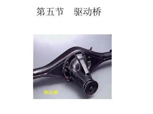
第五节 驱动桥与差速器
- 格式:ppt
- 大小:7.10 MB
- 文档页数:60
摘要汽车驱动桥是汽车的主要部件之一,其基本的功用是增大由传动轴或直接由变速器传来的转矩,再将转矩分配给左右驱动车轮,并使左右驱动车轮具有汽车行驶运动所要求的差速功能。
汽车差速器位于驱动桥内部,为满足汽车转弯时内外侧车轮或两驱动桥直接以不同角度旋转,并传递扭矩的需求,在传递扭矩时应能够根据行驶的环境自动分配扭矩,提高了汽车通过性。
其质量,性能的好坏直接影响整车的安全性,经济性、舒适性、可靠性。
随着汽车技术的成熟,轻型车的不断普及,人们根据差速器使用目的的不同,设计出多种类型差速器。
与国外相比,我国的车用差速器开发设计不论在技术上,还是在成本控制上都存在不小的差距,尤其是目前兴起的三维软件设计方面,缺乏独立开发与创新能力,这样就造成设计手段落后,新产品上市周期慢,材料品质和工艺加工水平也存在很多弱点。
本文认真地分析了国内外驱动桥中差速器设计的现状及发展趋势,在论述汽车驱动桥的基本原理和运行机理的基础上,提炼出了在差速器设计中应掌握的满足汽车行驶的平顺性和通过性、降噪技术的应用及零件的标准化、部件的通用化、产品的系列化等关键技术;阐述了汽车差速器的基本原理并进行了系统分析;根据经济、适用、舒适、安全可靠的设计原则和分析比较,确定了轻型车差速器总成及半轴的结构型式;轻型车差速器的结构设计强度计算运用了理论分析成果;最后运用CATIA软件对汽车差速器进行建模设计,提升了设计水平,缩短了开发周期,提高了产品质量,设计完全合理,达到了预期的目标。
关键词:驱动桥;差速器;半轴;结构设计;Automobile driving axle is one of the main components of cars, its basic function is increased by the transmission shaft or directly by coming from torque, again will torque distribution to drive wheels, and make about driving wheel has about vehicle movement required differential function. Auto differential drive to meet internal, located in car wheel or when turning inside and outside two axles directly with different point of view, and transfer the rotating torque transmission torque in demand, according to the environment should be driving torque, improve the automatic assignment car through sex. Its quality, performance will have a direct impact on the security of the vehicle, economy, comfort and reliability.As car technology maturity, the increasing popularity of small, people of different purposes according to differential, the design gives a variety of types differential. Compared with foreign countries, China's automotive differential development design whether in technology, or in the cost control there are large gap, especially at present the rise of 3d software design, lack of independent development and innovation ability, thus causing design means backward, new products listed cycle slow, materials quality and craft processing level also has many weaknesses.This paper conscientiously analyzes the differential drive axle design at home and abroad in the present situation and development trend of automobile driven axle, this basic principle and operation mechanism, carry on the basis of the differential practiced a meet the design should be mastered in smooth and automobile driving through sexual, noise reduction technology application and parts of standardization, parts of generalization, serialization of products, and other key technology; Expounds the basic principle and automotive differential system analysis; According to economic, applicable, comfortable, safe and reliable design principles and analysis comparison, determine the small differential assembly and half shaft structure type; Small differential structure design strength calculation using theoretical analysis results; Finally using CATIA software modeling design of automotive differential, promoted design level, shorten the development cycle, improve the product quality, design completely reasonable, can achieve the desired goals.Key words:Differential mechanism;Differential gear;Planetary gear;Semiaxis;目录1 绪论 (1)1.1 我国汽车驱动桥的现状分析 (1)1.2 我国汽车零部件的发展趋势 (2)1.3 本文研究主要内容 (2)2 汽车驱动桥的总体结构与差速器分类 (2)2.1 汽车驱动桥的总体结构及原理简介 (2)2.2 汽车驱动桥的设计要求 (5)2.3 差速器的组成与工作原理 (5)2.4 差速器的分类 (6)2.4.1 对称锥齿轮式差速器 (6)2.4.2 滑块凸轮式差速器 (9)2.4.3 蜗轮式差速器 (10)2.4.4 牙嵌式自由轮差速器 (11)3 普通圆锥齿轮式差速器设计 (12)3.1 普通圆锥齿轮式差速器的差速原理 (13)3.2 普通圆锥齿轮式差速器的结构 (14)3.3 普通圆锥齿轮式差速器的设计和计算 (14)3.3.1 行星齿轮数目的选择 (15)3.3.2 行星齿轮球面半径的确定 (15)3.3.3 行星齿轮与半轴齿轮齿数选择 (16)3.3.4 差速器圆锥齿轮模数及半轴齿轮节圆直径的初步确定 (17)3.3.5 压力角 (17)3.3.6 行星齿轮安装孔的直径及其深度 (18)3.3.7 差速器齿轮的几何计算 (18)3.3.8 差速器齿轮的强度计算 (20)3.4 差速器的材料 (21)3.5 差速器壳体设计 (22)3.5.1 差速器壳参数设计 (23)4 半轴的设计 (24)4.1 结构形式分析 (24)4.2 半浮式半轴杆部半径的确定 (25)4.3 半轴花键设计 (27)4.3.1 半轴的工作条件和性能要求 (29)4.3.2 选择用钢 (29)4.3.3 热处理工艺分析 (29)5 基于CATIA的差速器建模 (30)5.1 CATIA软件的介绍 (30)5.2 CATIA V5版本和应用领域介绍 (31)5.2.1 CATIA V5版本特点 (31)5.2.2 CATIA V5应用领域 (32)5.4 差速器的建模 (33)5.4.1 差速器零件建模 (33)5.4.2 差速器的装配 (37)总结 (38)参考文献 (39)致谢 (40)1 绪论自改革开放以来我国汽车产业发展迅猛,成为了我国的支柱产业。
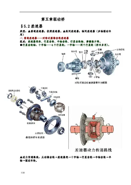
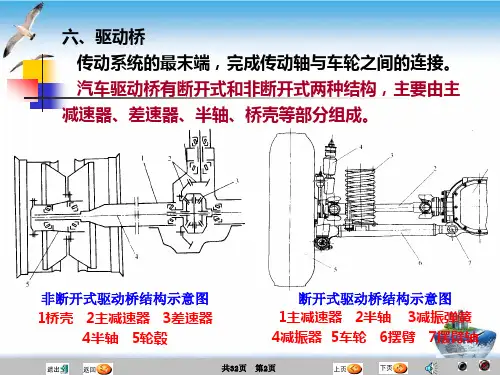
第五章驱动桥§5.2差速器类型:▲普通差速器;抗滑差速器。
▲轮间差速器;轴间差速器(多轴驱动车用)一.普通差速器——对称式圆锥齿轮差速器组成:差速器壳体、行星齿轮、半轴齿轮、行星齿轮轴、摩擦垫片等。
●行星齿轮轴:十字轴——4个行星轮;一字轴——两个行星轮(桥车多用)。
▲动力传递路线:从动锥齿轮→差速器壳→十字轴→行星齿轮→半轴齿轮→半轴→驱动车轮。
1.运动特性方程——差速器的差速原理设:差速器壳角速度为ωo(1)无差速时(行星轮无自转,只作公转)对行星轮A、B、C、三点,v相等,v =ωor则ω1=ω2=ωo(2)差速时(行星轮自转+公转)A点:行星轮使半轴齿轮转速加快;B点:行星轮使半轴齿轮转速减慢。
加快或减慢的量:ω4r故,半轴齿轮啮合点A的圆周速度ω1r = ωor + ω4r ①半轴齿轮啮合点B的圆周速度ω2r = ωor - ω4r ②①+ ②:ω1r + ω2r = 2ωorω1+ ω2= 2ωon1 + n2 = 2n o 即为差速器运动特性方程可见:●n1 = n2= no,车直线行驶;●若n1 = 0(一侧车轮不动),n2= 2no;●no = 0时,n1= - n2,(支起驱动桥,使一则车轮旋转,另一侧车轮会同速反转)●右转弯时, n1> no> n22.转矩分配设:差速器壳上作用转矩为Mo ,由Mo作用到十字轴的圆周P.P= Mo/r两半轴齿轮转矩:M1和M2(1)无差速时行星轮对两半轴齿轮作用力分别为Q1、Q2.则Q1 = Q2P = Q1 + Q2那么 Q1 = Q2= P/2 = Mo/(2r)M1 = Q1r = Mo/ 2M2 = Q2r = Mo/ 2即 M1 = M2= Mo/ 2可见,无差速时 Mo均分与两半轴齿轮。
(2)差速时两半轴齿轮端面摩擦力矩相等均为 Mbm,方向相反。
行星轮自转与十字轴产生摩擦力矩MT4,MT4作用于两半轴齿轮上产生作用力F1、F2,方向相反。
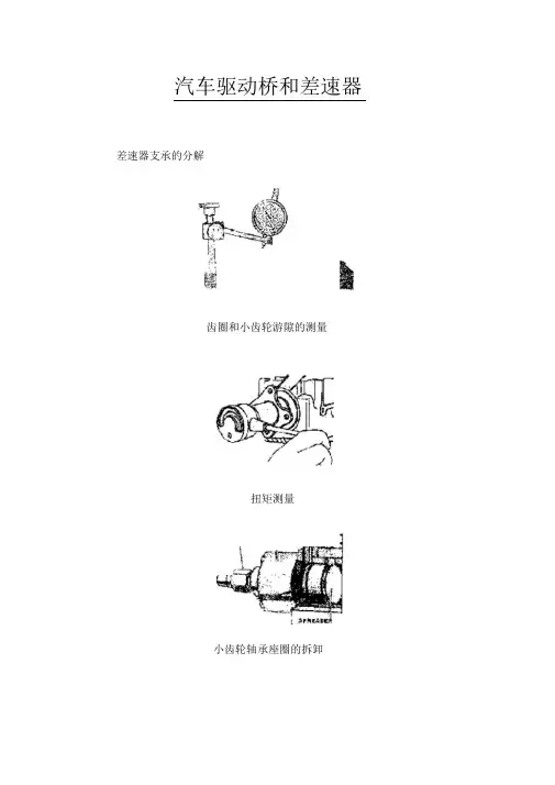
汽车驱动桥和差速器差速器支承的分解齿圈和小齿轮游隙的测量扭矩测量小齿轮轴承座圈的拆卸小齿轮轴承和深度垫圈(X)的安装1、拆下轴壳总成并固定在夹具上。
2、向下弯曲小齿轮螺母上的锁片,并测量和记录用扭力扳手转动小齿轮轴螺母时的总装配扭矩。
3、拆下轴壳后盖(如果有),并放完润滑油。
4、用撬杠撬出驱动轴法兰。
5、把显示器固定在壳体上,使指针承受点靠着齿圈,并测量和记录齿圈和传动齿轮的游隙。
6、在端轴承盖和壳体上冲压配合标记,连垫圈一起拆下轴承盖,接着拆下并丢弃驱动法兰油封。
端轴泵盖和垫圈总成通常决定齿圈和小齿轮的游隙以及端轴承的预加载荷,使垫圈组件保留在各自的端轴承盖上并分开存放总成以便组装。
7、从壳体上拆下差速器总成。
8、如图2,使用扭力扳手测量并记录小齿轮的扭矩。
9、用适当工具固定小齿轮法兰,并拆下小齿轮螺母和锁片。
10、用拉出器拆下小齿轮法兰和法兰油封。
11、从壳内压驱动齿轮和后轴承总成,注意不要损坏轴承或轴承表面,接着从壳上拆下前小齿轮轴承和垫圈。
12、如图3,用拉拔器从壳体上拆下轴承外圈,并把外圈和轴承放在一起,接着如图4,拆下小齿轮深度调整垫圈,并保留以备安装。
13、检查后小齿轮轴承,需要时用拉拔器把它从小齿轮上拆下来。
14、如图4,用拉拔器把小齿轮轴承座圈从壳体上拆下来,把座圈轴承放在一起。
拆下小齿轮深度调整垫圈,保留好以备安装。
15、从壳体上拆下速度传感器(如果装有),接着用溶剂清洁壳体、壳盖和法兰,并用压缩空气吹干。
确认所有异物都被除去,接顺序放置所有零件,注意轴承座圈、盖子和垫圈的安装位置,以保证安装正确,继续使用的各种零件都应装回其原来位置。
、安装和调整注意事项后桥分解、零部件更换后,小齿轮深度、小齿轮轴承预载、端轴承预载以及齿圈和小齿轮游隙必须调整为规定值。
齿圈和传动齿轮的齿面接触面必须调整正确,以保证其工作正常。
如果重新使用现有的齿圈、小齿轮、小齿轮轴承和壳体。
使用分解时拆下来的垫圈可以获得正确的小齿轮深度。
附录附录ADrive axle/differentialAll vehicles have some type of drive axle/differential assembly incorporated into the driveline. Whether it is front, rear or four wheel drive, differentials are necessary for the smooth application of engine power to the road.PowerflowThe drive axle must transmit power through a 90°angle. The flow of power in conventional front engine/rear wheel drive vehicles moves from the engine to the drive axle in approximately a straight line. However, at the drive axle, the power must be turned at right angles (from the line of the driveshaft) and directed to the drive wheels.This is accomplished by a pinion drive gear, which turns a circular ring gear. The ring gear is attached to a differential housing, containing a set of smaller gears that are splined to the inner end of each axle shaft. As the housing is rotated, the internal differential gears turn the axle shafts, which are also attached to the drive wheels.Fig 1 Drive axleRear-wheel driveRear-wheel-drive vehicles are mostly trucks, very large sedans and many sports car and coupe models. The typical rear wheel drive vehicle uses a front mounted engine and transmission assemblies with a driveshaft coupling the transmission to the rear drive axle. Drive in through the layout of the bridge, the bridge drive shaft arranged vertically in the same vertical plane, and not the drive axle shaft, respectively, in their own sub-actuator with a direct connection, but the actuator is located at the front or the back of the adjacent shaft of the two bridges is arranged in series. Vehicle before and after the two ends of the driving force of the drive axle, is the sub-actuator and the transmission through the middle of the bridge. The advantage is not only a reduction of the number of drive shaft, and raise the driving axle of the common parts of each other, and to simplify the structure, reduces the volume and quality.Fig 2 Rear-wheel-drive axleSome vehicles do not follow this typical example. Such as the older Porsche or Volkswagen vehicles which were rear engine, rear drive. These vehicles use a rear mounted transaxle with halfshafts connected to the drive wheels. Also, some vehicles were produced with a front engine, rear transaxle setup with a driveshaft connecting the engine to the transaxle, and halfshafts linking the transaxle to the drive wheels.Differential operationIn order to remove the wheel around in the kinematics due to the lack of co-ordination about the wheel diameter arising from a different or the same rolling radius of wheel travel required, inter-wheel motor vehicles are equipped with about differential, the latter to ensure that the car driver Bridge on both sides of the wheel when in range with a trip to the characteristics of rotating at different speeds to meet the requirements of the vehicle kinematics.Fig 3 Principle of differentialThe accompanying illustration has been provided to help understand how this occurs.1.The drive pinion, which is turned by the driveshaft, turns the ring gear.2.The ring gear, which is attached to the differential case, turns the case.3.The pinion shaft, located in a bore in the differential case, is at right angles to the axle shafts and turns with the case.4.The differential pinion (drive) gears are mounted on the pinion shaft and rotate with the shaft .5.Differential side gears (driven gears) are meshed with the pinion gears and turn with the differential housing and ring gear as a unit.6.The side gears are splined to the inner ends of the axle shafts and rotate the shafts as the housing turns.7.When both wheels have equal traction, the pinion gears do not rotate on the pinion shaft, since the input force of the pinion gears is divided equally between the two side gears.8.When it is necessary to turn a corner, the differential gearing becomes effective and allows the axle shafts to rotate at different speeds .Open-wheel differential on each general use the same amount of torque. To determine the size of the wheel torque to bear two factors: equipment and friction. In dry conditions, when a lot of friction, the wheel bearing torque by engine size and gear restrictions are hours in the friction (such as driving on ice), is restricted to a maximum torque, so that vehicles will not spin round. So even if the car can produce more torque, but also need to have sufficient traction to transfer torque to the ground. If you increase the throttle after the wheels slip, it will only make the wheels spin faster.Limited-slip and locking differential operationFig 5 Limited-slip differentialDifferential settlement of a car in the uneven road surface and steering wheel-driven speedat about the different requirements; but is followed by the existence of differential in theside car wheel skid can not be effective when the power transmission, that is, the wheel slipcan not produce the driving force, rather than spin the wheel and does not have enoughtorque. Good non-slip differential settlement of the car wheels skid on the side of the powertransmission when the issue, that is, locking differential, so that no longer serve a usefuldifferential right and left sides of the wheel can be the same torque.Limited-slip and locking differential operation can be divided into two major categories:(1) mandatory locking type in ordinary differential locking enforcement agencies toincrease, when the side of the wheel skid occurs, the driver can be electric, pneumatic ormechanical means to manipulate the locking body meshing sets of DIP Shell will be withthe axle differential lock into one, thus the temporary loss of differential role. Relatively simple structure in this way, but it must be operated by the driver, and good roads to stop locking and restore the role of differential.(2) self-locking differential installed in the oil viscosity or friction clutch coupling, when the side of the wheel skid occurs when both sides of the axle speed difference there, coupling or clutch friction resistance on the automatic, to make certain the other side of the wheel drive torque and the car continued to travel. When there is no speed difference on both sides of the wheel, the frictional resistance disappeared, the role of automatic restoration of differentials. More complicated structure in this way, but do not require drivers to operate. Has been increasingly applied in the car. About non-slip differential, not only used for the differential between the wheels, but also for all-wheel drive vehicle inter-axle differential/.Gear ratioThe drive axle of a vehicle is said to have a certain axle ratio. This number (usually a whole number and a decimal fraction) is actually a comparison of the number of gear teeth on the ring gear and the pinion gear. For example, a 4.11 rear means that theoretically, there are 4.11 teeth on the ring gear for each tooth on the pinion gear or, put another way, the driveshaft must turn 4.11 times to turn the wheels once. The role of the final drive is to reduce the speed from the drive shaft, thereby increasing the torque. Lord of the reduction ratio reducer, a driving force for car performance and fuel economy have a greater impact. In general, the more reduction ratio the greater the acceleration and climbing ability, and relatively poor fuel economy. However, if it is too large, it can not play the full power of the engine to achieve the proper speed. The main reduction ratio is more Smaller ,the speed is higher, fuel economy is better, but the acceleration and climbing ability will be poor.附录B驱动桥和差速器所有的汽车都装有不同类型的驱动桥和差速器来驱动汽车行驶。