Turbo Code Implementation Issues for Low Latency
- 格式:pdf
- 大小:90.01 KB
- 文档页数:10
Turbo C 2.0常见错误Turbo C 2.0编译器能查出程序的三类错误:致命错误、一般错误和警告。
·致命错误通常是内部编译出错,一般很少发生。
发生致命错误时,编译立即停止,用户必须采取一些适当措施,并重新编译。
·一般错误指程序的语法错误、磁盘或内存存取错误或命令行错误等。
发生一般错误时,编译程序仍将完成本次编译,尽可能多地发现语法错误,然后停止。
·警告指出一些值得怀疑的情况,而这些情况本身可以成为源程序的一部分。
发出警告信息时,编译程序将继续进行编译。
另外,警告信息并不阻止程序的执行。
编译程序首先输出错误类型,然后输出源文件名、出错位置(行号)和错误信息。
下面按字母顺序,分别列出一般错误和警告。
对每一条信息,将提供产生的可能原因和纠错方法。
1.一般错误·#operator not followed by macro argument name(在宏定义中,#后未跟宏变量名)·…XXX‟not an argument(“XXX”不是函数参数)·Ambiguous symbol …XXX‟(不明确的符号“XXX”)·Argument #missing name(参数#名丢失:若使用函数原型应包含所有参数)·Argument list syntaxerror(参数表语法错误:参数间要用逗号分开)·Array bounds missing(丢失数组界限符)·Array size too large(数组长度太大:可用的内存不够)·Assembler statement too long(汇编语句太长:不能超过480字节)·Bad character in parameters(参数中有不适当的字符)·Bad configuration file(配置文件不正确:配置文件命令选择项必须以一短划线(-)开始)·Bad ifdef/ifndef/undef directive syntax(ifdef/ifndef/undef指令语法错)·Bad file name format in include directive(包含命令中文件名格式不正确)·Bad file size syntax(位段长度语法错:位段的长度必须是l—16的常量表达式)·Call of non-function(调用未定义的函数)·Cannot modify a const object(不允许修改常量对象)·Case outside of switch(漏掉了case语句:通常由括号不匹配引起)·Case statement missing(case语句出错:可能丢失了冒号)·Case syntax error(case语法错误)·Character too long(字符常量太长:只能是1个字符或转义字符)·Compound statement missing(复合语句丢失:通常是花括号不匹配)·Conflicting type modifiers(不明确的类型修饰符)·Constant expression required(要求常量表达式:如数组的大小须是常量表达式)·Conversion of near pointer not allowed(不允许转换近指针)·Could not find file…XXX‟(找不到“XXX”文件)·Declaration missing ;(说明中丢失分号)·Declaration needs type or storage class(说明中需要数据类型或存储类型)·Declaration syntax error(说明中语法错)·Default outside of switch(default子句出现在switch外)·Define directive needs an identifier(#define指令需要一个标识符)·Division by zero(除数为0)·Do statement must have whi,le(do语句必须要有while)·Do-while statement missing {(do-while语句缺左括号)·Do-while statement missing }(do-while语句缺右括号)·Do-while statement missing ;(do-while语句缺少分号)·Duplicate Case(case情况不惟一:须有一个惟一的常量表达式)·Enum syntax error(Enum类型语法错)·Enumeration constant syntax error(枚举常量语法错)·Error directive:XXX(错误指令:XXX)·Error writing output file(写输出文件错:一般由磁盘空间不够造成)·Expreesion syntax error(表达式语法错)·Extra parameter in call(调用时出现多余参数)·Extra parameter in call to XXX(调用函数XXX时出现多余参数)·File name too long(文件名太长)·For statement missing ((for语句缺左括号)·For statement missing )(for语句缺右括号)·For statement missing;(for语句缺少分号)·Function call missing )(函数调用缺右括号)·Function definition out of place(函数定义位置错:函数定义不可嵌套)·Function does not take a variable number of argument(函数不接受可变的参数个数) ·Goto statement missing label(goto语句缺少标号)·If statement missing ((if语句缺左括号)-·If statement missing )(if语句缺右括号)·Illegal character …(‟(非法字符“(”)·Illegal initialition(非法初始化)·Illegal octal digit(非法的八进制数)·Illegal pointer subtraction(非法的指针相减:由于非指针变量减指针变量引起) ·Illegal structure operation(非法的结构操作)·Illegal use of floating point(非法使用浮点数:浮点数不允许出现在位运算、条件运算中) ·Illegal use of pointer(非法使用指针)·Improper use of atypedef symbol(typedef使用不当)·In-line assembly not allowed(内部扎:编不允许)·1ncompatlble storage class(不相容的存储类型)·1ncompatlble type conversion(不相容的类型转换:如函数与非函数之间转换) ·Incorrect command line argument:XXX(不正确的命令行参数:XXX)·Incorrect connguranon file eargument:XXX(不正确的配置文件参数:XXX) ·Incorrect number format(不正确的数据格式)·Incorrect use of default(不正确地使用dehult)·Initializer syntax error(初始化语法错)·Invalid indirection(无效的间接运算操作符:间接运算操作符要有非空的指针变量) ·Invalid macor argument separator(无效的宏参数分隔符)·Invalid pointer addition(无效的指针相加)·Invalid use of arrow(无效的箭头使用)·Invalid use of dot(无效的点使用)·Lvalue required(要求是一个逻辑值)·Macro argument syntax error(宏参数语法错)·Macro expansion too long(宏扩展太长)·Mismatch number of parameter in definition(定义中参数个数不匹配)·Misplaced break(break语句位置错)·Misplaced continue(continue语句位置错)·Misplaced decimal pomt(十进制小数点位置错)·Misplaced else(else位置错:else缺少与之匹配的if语句)·Muplaced elif/else/endif directive(elif/else/endif指令位置错)·Must be addressable(必须是可编址的)·Must take address of memory locatlon(必须是一个内存地址)·No file name ending/glven(文件名无结束符或未给出文件名)·Non-portable pointer assingnment(不可移植的指针赋值:将一个指针值给—个非指针,或者相反(除0可赋值给一个指针变量外))·Non-portable pointer compraslon(不可移植的指针比较:将一个指针与一个非指针比较)·Non-portable return type compraslon(不可移植的返回类型转换:类型不一致)·Not an allowed type(不允许的类型)·Out of memory(内存不够)·Pointer required on left side of(操作符左边必须是一个指针)·Redeclaration of …XXX‟(“XXX”重复定义)·Size of structure or array not known(结构或数组大小不定)·Statement missing;(语句缺分号)·Structure size too large(结构太大)·Subscription missing ](下标缺右方括号)·Switch statement missing {(switch语句缺左括号)·Switch statement missing }(switch语句缺右括号)·Too few parameter in call(函数调用参数太少)·Too few parameter in call to…XXX‟(调用函数“xxx”时,参数太少)·Too many cases(太多的case句:一个switch语句中允许有<257个case语句)·Too many decimal points(十进制小数点太多)·Too many default cases(默认情况太多)·Too many exponents(阶码太多)·Too many initializer(初始化太多)·Too many storage in declaration(说明中存储类型太多)·Too many types in declaration(说明中类型太多)·Too much auto memory in function(函数中自动存储太多)·Too much code define in file(文件中定义的代码太多:允许<64K)·Too much global data define in file(文件中定义的全局数据太多:允许<64K)·Two consecutive dots(两个连续点)·Type mismatch in parameter#(参数#类型不匹配)·Type mismatch in parameter…XXX‟(参数“XXX'‟类型不匹配)·Type mismatch in parameter #XXX in call to…XXX‟(调用函数“XXX”时,参数#XXX类型不匹配)·Type mismatch in parameter…XXX‟in call to…XXX‟(调用函数“XXX”时,参数“XXX'‟类型不匹配)·Type mismatch in parameter of…XXX‟(重定义“XXX'‟类型不匹配)·Unable to create output file…XXX.XXX‟(不能创建输出文件“XXX.XXX”)·Unable to execute command…XXX‟(不能执行“XXX”命令:找不到TLINK或MASM,或者磁盘出错) ·Unable to create turbo.1nk(不能创建turbo.lnk:编译程序不能创建临时文件TURBOC.$LN,因为不能存取磁盘或磁盘已满)·Unable to open include/input file…XXX‟(不能打开包含/输入文件“XXX”)·Undefined label…XXX‟ (标号“XXX”未定义)·Undefined structure…XXX‟ (结构“XXX'‟未定义)·Undefined symbol…XXX‟ (符号“XXX”未定义)·Unexpected end of file in comment started on line#(文件在某个注释中意外结束:可能缺少了*/)· Unexpected end of file in conditional started on line#(文件在条件语句中意外结束:可能缺少了#endif) ·Unknow npreprocessor directive…XXX‟ (未知的预处理指令“XXX”)·Unterminated character constant/string(未终结的字符常量/串)·Unterminated string or character constant(未终结的串或字符常量)·User break(用户中断:由用户按下[Ctrl-Break]键造成)·While statement missing {(while语句缺左括号)·While statement missing }(while语句缺右括号)·Wrong number of argument in of…XXX‟ (调用“XXX”时,参数个数不对)2.警告·…XXX‟declared but never used(“xxx”声明了但从未使用过)·…XXX‟isassigned a value which is never used(“XXX”被赋予一个从未用过的值)·…XXX‟not part of structure(“XXX”不是结构的一部分)·Ambiguous operators need parentheses(不明确的运算符需要括号)·Both return and return of a value used(既用返回,又用返回值:编译器发现一个与前面的return语句不一致的return语句)·Call to function without prototype(调用无原型函数)·Call to function…XXX‟without prototype(调用无原型函数“XXX”)·Code has no effect(无效代码)·Constant out of range in comparision(作比较时常量超出范围)·Constant is long(常量是long类型)·Conversion may lose significant digits(转换可能丢失高位数字)·Function should return a value(函数应该有一个返回值:除void外)·Mixing pointers to signed and unsigned char(混淆signed和unsigned字符指针)·No declaration for function…XXX‟ (函数“XXX”未说明)·Non-portable pointer assignment(不可移植的指针赋值)·Non-portable return conversion(不可移植的返回类型转换)·Parameter…XXX‟is never used(参数“XXX”从未使用过)·Possible use of…XXX‟before definition(在定义之前可能已使用“XXX”)·Possible incorrect assignment(赋值可能不正确)·Redefinition of…XXX‟is not identical(重定义“XXX”不相同)·Restarting compiler using assembly(用汇编重新启动编译)·Structure passed by value(结构按值传送)·Superfluous & with function or array(在数组或函数中有多余的&)·Suspicious pointer conversion(可疑的指针转换)·Undefined structure…XXX‟ (未定义的结构“XXX”)·Unknown assembler instruction(未知的汇编指令)·Unreachable code(不可达代码:无标号或循环语句的结束符)·Void function may not return a value(空函数不可返回一个值)·Zero length structure(结构长度为0)。

Hans Journal of Wireless Communications无线通信, 2014, 4, 57-62Published Online June 2014 in Hans. /journal/hjwc/10.12677/hjwc.2014.43010Implementation of Turbo Code SimulationBased on SimulinkDing WangHangzhou Dianzi University, HangzhouEmail: wd158********@Received: May 12th, 2014; revised: May 19th, 2014; accepted: May 26th, 2014Copyright © 2014 by author and Hans Publishers Inc.This work is licensed under the Creative Commons Attribution International License (CC BY)./licenses/by/4.0/AbstractThis paper describes the basic structure of Turbo code scheme, and presents a Simulink model ofa Turbo encoder and decoder. Turbo encoder concatenates two same sub-encoders in parallelthrough interleaver. The iteration decoder is based on APP (A Posteriori Probability) decoder block in Simulink, so the process of coding becomes convenient and vivid. Then, based on the si-mulation we made, some main factors (such as interleaver length, iteration times, decoding algo-rithm) which will affect the performance of Turbo codes are studied, and the corresponding emu-lation results and the analysis are given. It has some reference value to the actual system design.KeywordsTurbo Code, Simulink, A Posteriori Probability Decoder一种基于Simulink的Turbo码仿真实现王丁杭州电子科技大学,杭州Email: wd158********@收稿日期:2014年5月12日;修回日期:2014年5月19日;录用日期:2014年5月26日摘要介绍了Turbo码的编解码原理,并且提出了一种完全基于Simulink模块的Turbo码仿真模型。
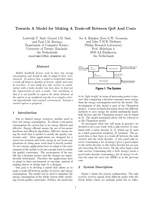
Towards A Model for Making A Trade-offBetween QoS And CostsLodewijk T.Smit,Gerard J.M.Smit, and Paul J.M.Havinga Department of Computer Science,University of Twente,Enschede,the Netherlandsemail:smitl@cs.utwente.nl Jos A.Huisken,Kees G.W.Goossens, and John T.M.H.DielissenPhilips Research Laboratory,Prof.Holstlaan4,5656AA Eindhoven,the NetherlandsAbstractMobile handheld devices need to have low energy consumption and should be able to adapt to their envi-ronment.To achieve this,a model is needed that makes a trade-offbetween Quality of Service(QoS)and costs at run-time.A case study of a rake receiver in combi-nation with a turbo decoder has been done tofind out the requirements of such a model.Our conclusion is that it is not feasible to express the whole behavior of the system in an analytical way due to a complex exter-nal unpredictable time-variant environment.Instead a control system is proposed.1IntroductionDue to limited energy resources,mobiles need to have low energy consumption.To obtain a low-power consumption the system has to be energy efficient and effective.Energy efficient means the use of low-power hardware and efficient algorithms.Effective means do-ing the work that is needed to satisfy the quality con-straints only.Most applications are designed for a worst-case scenario and waste energy in not worst-case situations by doing more work than is strictly needed. To save energy,applications have to adapt to the envi-ronment of the mobile to do just enough work to satisfy the quality constraints.The environment of the mo-bile has a dynamic nature,and the changes are unpre-dictable beforehand.Therefore the applications have to adapt to their environment at run-time,instead of making choices at design time by a designer.Our goal is to develop a model that allows us to make a trade-offbetween quality of service and energy consumption.The model can be used to minimize the energy consumption of the whole system while satisfy-ing certain quality constraints.Further,the model hasFigure1.The Systemto be’light weight’in terms of processing power to pre-vent that computing a decision consumes more energy than the energy consumption saved by the model.The development of this model is part of the Chameleon project.A more in-depth discussion about the different methods to save energy for mobile multimedia hand-held devices and the Chameleon project can be found in[8].The model mentioned above will be referred to as the Chameleon model.To investigate what this will mean in practice,we decided to do a case study with a rake receiver[5]com-bined with a turbo decoder[2,3],which can be used in a third generation telephony[4]terminal.The ge-neral idea is that there is a trade-offbetween the rake receiver and the turbo decoder.A very good rake re-ceiver(consuming a lot of energy)gives a good output to the turbo decoder,so the turbo decoder has an easy job correcting the few errors.On the other hand a bad rake receiver(consuming only a little energy)needs a good turbo decoder(consuming a lot of energy)to ob-tain the same bit error rate(BER)as in the previous case.2System DescriptionFigure1shows the system configuration.The rake receiver receives signals from different paths with dif-ferent delays(there are multiple paths due to reflec-1tions)and combines them to construct one output sig-nal.Each recognized path element is correlated with a code in afinger to retrieve the original signal.This basic principle of a rake receiver is shown in Figure2. For a more detailed description,see[4,9].Figure2.Basic Principle Of A Rake ReceiverThe soft output signal of the rake receiver is a signed x bits value.A high output value means a high pro-bability that a1was transmitted;a low value means a high probability that a0was transmitted.The turbo decoder is an error correcting decoder,which will get the values of the rake receiver as input and produces hard bits(0or1)on the output.A block diagram is of the turbo decoder is shown in Figure3.The turbo decoder is constructed out of two decoders,an inter-leaver,and a deinterleaver.The output of each decoder is passed to each other,to improve the output of the decoders by use of a-priori information.This iterative principle gives the turbo decoder a better performance than a conventional decoder.Between the decoders, the data is(de)interleaved.More details about turbo decoding can be found in e.g.[10].The Quality of Service(QoS)manager(see Fig.1)determines the(current)values for the parameters of the rake and the turbo decoder making a trade-offbetween the costs and the performance using the Chameleon model.The minimal requested quality is an input constraint for the QoS manager.There are a lot of parameters that affect the qua-lity(and consequently the costs).However,many pa-rameters are determined by the external environment (e.g.number of paths and interference).These”ex-ternal”parameters have a considerable influenceonFigure3.Block Diagram Of Turbo Decoderthe system.Therefore the QoS manager has to takeinto account the effects of changes of these parameters, but the QoS manager cannot change them.Further,the values of some parameters are determined at or al-ready before design time(e.g.chiprate)and cannot be changed(easily)at run-time.The two most important trade-offparameters for a rake receiver and a turbo decoder that can be changedby the Chameleon model are the number offingers andthe number of iterations.The number offingers is equal to the number of multipaths that are combined,the number of iterations states how many times theturbo decoding algorithm runs before making a hard decision about the value of the output bit.Atfirststart,we will restrict our QoS manager to these two parameters.Further,we define that quality is equiv-alent to the bit error rate performance and that costsare equivalent to the arithmetic complexity.3ModelOur goal is to construct a model that minimizes thecosts given a set of constraints.This looks like a typical(non-linear)optimization problem known from opera-tions research[12].The cost function to be minimizedis the sum of the cost function for the rake receiverand the cost function for the turbo decoder.The set of constraints exists of(1)a quality function that mustsatisfy a minimum threshold for the required minimum quality of service and(2)limits on the range of para-meters(e.g.the number offinger must be between1and10).Note that the quality function is not the sum of two quality functions for the rake receiver and theturbo decoder,because the quality of the turbo decoderis dependent on the quality output of the rake receiver.The cost and quality functions will be discussed belowin more detail.3.1Cost FunctionThe essence of a rake receiver is correlation of theincoming chips(transmitted pulses)with a code.If thenumber of operations for this correlation are c per chip, then the total number of operations per bit needed forthe arithmetic of the rake receiver are c·sf·co·ch,where sf is the spreading factor(sf is equal to number of chips per bit),co is the number of correlators and ch is the number of channels.Note that correlators are needed also for channel estimation and searching,so the number of correlators is greater than the num-ber offingers.Further,most rake receiver designs are more complex(having tracking algorithms,advanced filters,etc.)that make the performance better and the2arithmetic complexity higher.In most cases,after the correlation the signal is multiplied with a gain factor before the combining operation,also raising the compu-tation costs.So,the exact costs depends on the design and implementation,but in general the costs per bit are proportional of sf·co·ch.With regard to the turbo decoder,the number of operations per bit is about linear to the number of iterations of the turbo-decoding algorithm.There exist different turbo decoding algorithms with different costs and performance.Three frequently used algorithms are Max-Log-MAP,Log-MAP and SOVA.The costs per bit are shown in the table below[6]:Operation Log-MAPmax ops5x2M-2additions15x2M+9mul by±18bit compslook-ups5x2M-215x2M-173x2M+9x M+2510376A turbo decoders contains also two(de)interleavers. The number of operations per bit for the interleavers dependents on their implementation.We assume these costs about i.Each iteration the decoding algorithm is executed twice.The number of operations needed for the turbo decoder per bit is about n·(2·103+2·i), using the Max-Log-MAP algorithm and an encoder with3memories,where n is the number of iterations. The(third generation)Universal Mobile Telecom Sys-tem(UMTS)always uses three memories in the en-coder.So,the costs are linear with the number of exe-cuted iterations.Note that this is only the arithmetic cost,e.g.control costs are not included.The cost function of the system is simply the sum of the cost function of the rake receiver and the cost function of the turbo decoder.3.2Quality FunctionProblems arose when we tried to define the quality function which gives the bit-error-rate for a certain sit-uation.Different approaches we used:•Analytical derivation of quality function•Approximate a quality function•Eliminate the need for a quality function3.2.1Analytical derivation of quality functionFor both the rake receiver and the turbo decoder,there are a lot of parameters that influence the quality of ser-vice.Most of them are unpredictable(quickly chang-ing)environment parameters.There are almost no analytical expressions known from literature for ex-pressing the quality of service,and those that are,are restricted to special cases.Most results in both rake receiver and turbo decoder research areas are obtained by simulations,not by analytical work.A complicat-ing factor is that the quality of the turbo decoder is dependent on the quality of the output of the rake re-ceiver,so the quality function cannot be split up eas-ily into two separate parts.Most research focuses on the rake receiver or on the turbo decoder,but usu-ally not on their combination.Furthermore,most re-search for the turbo decoder assumes an additive white Gaussian noise(AWGN)channel model,whereas re-search with regard to the rake receiver usually assumesa Rayleigh fading or Racian channel model.These dif-ferences make it difficult to combine these two subjects and to derive a quality function for the whole system.Our conclusion is that when experts with thorough sys-tem knowledge use simulations for small parts of the whole system due to the complexity,it is not feasible to derive an analytical function for the whole system.3.2.2Approximate a quality functionIf it is not feasible to define a quality function that gives an exact indication of the quality,we can try to derive a quality function that gives an approximation of the quality.Because it’s not possible to do it in an analytical way,we need data.The idea is to derive an analytical function by means of regression and interpo-lation.To get the necessary data we could use results from literature or do a lot of simulations.We started with thefirst possibility.Researchers only cover one or a few aspects of the rake receiver or turbo decoding due to the complex-ity.All the parameters except one or a few arefixed.Results are presented for this specific aspect.How-ever,different researchers use different simulation en-vironments by making different assumptions(such as different channel models,neglecting sometimes certain things(e.g.Doppler effect),simplifying the real world(e.g.assuming a time invariant environment))andfix-ing different parameters.These differences make it hard to combine the different results and to draw valid conclusions for the overall system.Beside this fact, the amount of data is very limited.Most times,only a few plots are presented.So,there are only a few data points.However,due to the large number of parame-3ters,there is a very large N-dimensional space.This means that there is not enough data to derive an ana-lytical function for the quality of service.Note that doing the simulations by ourselves will not solve the last problem.3.2.3Eliminate the need for a quality function After this observation,the question raised whether it is really necessary that the quality of service function has to be known.Of course,this is the most convenient situation,but in a lot of other real life circumstances, things can be regulated without knowing all the para-meters and all the details.E.g.a thermostat can per-fectly regulate the temperature without knowing any-thing about the environment(like incoming sunlight, status offireplace,open doors)just by measuring tem-perature and regulating the amount of appended heat. The only”knowledge”of the system is that adding heat will increase the temperature.Something similar can be done in our case.We know that changing a parameter will make the quality better or worse.However,the exact amount of the difference is not exactly known.To get a better indication about how much a change will contribute to a quality increase or decrease,afirst derivative could be calculated over the last differences.There are a few potential problems with this approach.First,the number of parameters on the receiver side that could be changed should be low.Due to the fact that it is unknown what the qua-lity increase or decrease will be,different combinations have to be tried out,if the quality has to be changed. If there are too many parameters,the number of pos-sibilities will be too large.Secondly,as already stated, this approach could not give a prediction of the qua-lity on beforehand.Consequently,a kind of learning curve is needed,before a’stable’situation is reached.A third problem is a parameter with a quality function with more than one optimum.The discovered optimum could be a local optimum instead of a global optimum.The configuration will look like Figure4.Figure4.The Control SystemQuality MeasurementBoth the rake receiver as well as the turbo decoder can be implemented with a facility to deliver infor-mation that can be used to determine the quality of service.The rake receiver can deliver the channel esti-mation information(which has to be collected anyway).The channel estimation provides information about the number of paths and their phase and amplitude,so this can be used as an indication of the quality of the in-put channel.With regard to the turbo decoder early stop algorithms[7,13]are known,which prevent un-necessary iterations if the data no longer contains er-rors(that the turbo decoder is able to correct).The average number of iterations that is needed to correct the data is a measure for the BER performance of the output of the turbo decoder.The quality of the system is determined by thefinal output,so the output of the turbo decoder has to be compared with the given quality constraint.The qua-lity information given by the rake receiver is however also useful.This information can be used as extra in-formation used tofine-tune the decisions made by the model(e.g.ensure that the number offinger is always equal or smaller than the number of paths).Quality Function CharacteristicIn case of the rake receiver,addingfingers will give a better performance,until the number offingers will be-come larger than the number of recognized multipaths[1].If the number offingers becomes too large,then theperformance will degrade,because of adding noise for the unrecognized paths to the signal with the maximal ratio combining.The plot of the quality as function of the number offingers will look like the right plot of Figure5.In case of the turbo decoder,the quality will be the same or better after each iteration,but never be lower.Thefirst iterations deliver more gain than the last iter-ations[11].Therefore,the plot of the quality(y-axis) as function of the number of iterations(x-axis)of the turbo decoder will look like the left plot of Figure5.Note that the exact numbers are unknown and depend on a lot of parameters.ControlWith the known cost function and the data collected through measurements of the quality,decision rules must make the trade-offs to minimize the costs within the given constraints.Due to limited space,not all the decisions rules are discussed here.The principle is that a prediction for the quality and cost increase or de-4Q u a l i t ynumber of iterationsturbo decoder Q u a l i t ynumber of fingersrake receiverFigure 5.Quality Functions For The Turbo De-coder (left)And The Rake Receiver (right)crease can be made using the first derivative.The first derivative of the cost function is always known.The first derivative of the quality function must be based on the information gathered from changes in the history.In case there is no history,small changes can be made to parameters to collect information to obtain the first derivative.These changes are not allowed to cause a vi-olation of the quality constraint,so they should always (temporarily)improve the quality.Due to the dynamic environment,the quality and the value of the first derivative could change every moment.The first derivative of the quality functions gives only a rough guess about what will happen when changing the parameter,not an exact estimate.The same approach can be used with an extended set of parameters (not only the number of turbo decoding iterations and rake fingers).However,as mentioned,the set has to be limited and has to satisfy the rules that there is maximum one optimum.4Conclusion And Future WorkThe quality of service of the current situation or a prediction for the future can not be determined analy-tically,due to unpredictable influences of the environ-ment which have a considerable impact on the quality of service of the system.Our proposal is to measure the quality and to control the system dependent on these measurements using predefined decision rules.A next step in our research is to simulate the whole system to define the decision rules in detail and to evaluate this approach.AcknowledgementsThis research is conducted within the Chameleon project (TES.5004)supported by the PROGram for Research on Embedded Systems &Software (PROGRESS)of the Dutch organization for Scientific Research NWO,the Dutch Ministry of Economic Af-fairs and the technology foundation STW.We thankPhilips for a very pleasant stay at the Natlab research laboratory in Eindhoven during the research period.References[1] F.Adachi.Effects of orthogonal spreading and rakecombining on ds-cdma forward link in mobile radio.IEICE mun.,E80-B(11):1703–1712,Nov.1997.[2] C.Berrou and A.Glavieux.Near optimum error cor-recting coding and decoding:Turbo-codes.IEEE Transactions on Communications ,44(10):1261–1271,Oct.1996.[3] C.Berrou,A.Glavieux,and P.Thitimajshima.Nearshannon limit error-correcting coding and decoding:Turbo codes.In Proc.International Conference on Communications (ICC),pages 1064–1070,May 1993.[4]T.Ojanper¨a .Wideband CDMA for Third GenerationMobile Communications .The Artech House Universal Personal Communications Series.Artech House,1998.ISBN:0-89006-735-X.[5]R.Price and P.Green.A communication techniquefor multipath channels.In Proceedings of the IRE ,volume 46,pages 555–570,Mar.1958.[6]P.Robertson,E.Villebrun,and P.Hoeher.A com-parison of optimal and sub-optimal map decoding al-gorithms operating in the log domain.In Proc.Inter-national Conference on Communications (ICC),pages 1009–1013,June 1995.[7]R.Y.Shao,S.Lin,and M.P.Fossorier.Two sim-ple stopping criteria for turbo decoding.IEEE Trans-actions on Communications ,47(8):1117–1120,Aug.1999.[8]G.J.Smit,P.J.Havinga,M.Bos,L.T.Smit,andP.M.Heysters.Reconfiguration in mobile multime-dia systems.In Proc.of PROGRESS workshop 2000,pages 95–105,Oct.2000.[9]G.L.Turin.Introduction to spread-spectrum anti-multipath techniques and their application to urban digital radio.Proc.of the IEEE ,68(3):328–353,Mar.1980.[10]M.C.Valenti.Iterative Detection and Decoding forWireless Communications .PhD thesis,Virginia Poly-technic Institute and State University,July 1999.[11] C.C.Wang.On the performance of turbo codes.InProc.IEEE MILCOM 1998,pages 987–992,Oct.1998.[12]W.L.Winston.Operation Research :Applicationsand algorithms .Duxbury press,3edition,1994.[13] A.Worm,H.Michel, F.Gilbert,G.Kreiselmaier,M.Thul,and N.Wehn.Advanced implementation issues of turbo-decoders.In Proc.2nd International Symposium on Turbo-Codes and Related Topics ,Sept.2000.5。

Using the Altium Designer RTLContentsError formatting macro: toc: ng.NullPointerExceptionThe Altium Designer Run Time Library (RTL) is composed of Application Programming Interfaces (APIs), specialized classes and system routines. Each API has an Object Model and in turn, the object model is a hierarchical system of object interfaces. These object interfaces represent actual objects in the Altium Designer.In the scripting system, we refer to the Object Models because we are dealing only with object interfaces that represent objects in the Altium Designer. An object model is a subset of the API. For example, the PCB Object model is part of the PCB API.With server development, we are dealing with classes, objects and object interfaces. Therefore, we will refer to APIs (remember each API also includes the specific Object model).The major APIs from the Altium Designer RTL are: Client/Server API, Workspace Manager API, PCB API, Schematic API and Integrated Library API.This document covers the following areas:∙The DXP software Technology Platform∙Altium Designer RTL used in Scripting∙Altium Designer RTL used in Server Development∙Using Object Models in Scripts and Server Projects∙Client and Server Interfaces∙Workspace Manager Interfaces∙Schematic Editor Interfaces∙PCB Editor Interfaces∙Integrated Library InterfacesDXP Software Technology PlatformFigure 1. Client - Executable / Server - DLL ParadigmAltium Designer's open architecture is the DXP platform which allows scripters and third party developers to write and integrate their modules into the environment, with full Application Programming Interface (API) access to the Schematic editor, PCB editor and other plug in editors.Several major software technologies are used in Altium Designer: theclient/server architecture technology, APIs, DXP Object Models, and object oriented technologies.Altium Designer provides a hybrid interface model, which exposes the functionality of a dynamic linked library (DLL) module to both a user and the client executable system. The servers themselves are built using the Altium Designer Run Time Library.The Client executable is a standalone executable system that collaborates with loaded dynamic library linked servers within Altium Designer. The Client module controls the user interface and delegates tasks (sends commands) to appropriate servers, while servers (as dynamic linked library files) concentrate solely on providing specific functionality based on the commands invoked by the user in Altium Designer.An Editor Server provides Specialised ServicesFigure 2: The server responds to the processs sent by the Client module and then acts on the current associated document.An editor server provides its services in Altium Designer. The DXP platform interprets the tasks in terms of commands and then delegates these commands to the appropriate server.The server responds by activating its required functionality on this currently focussed design document.For example, when a user is clicking on the Schematic menu to place a wire, the system interprets this action as a Sch: PlaceWire command and delegates the command to the Schematic Editor.The Schematic server responds by executing the command. The functionality of a server that is installed in the Altium Designer is exposed by that server's processes and its exposed functions.Main Servers in Altium DesignerThe Workspace Manager module is a system extensions server coupled tightly with the client module within Altium Designer and it deals with projects and their associated documents. This server provides compiling, multi sheet design support, connectivity navigation tools, multi-channel support, multiple implementation documents and so on. The Workspace manager manages output generators such as netlisters.Figure3: A project and its design documents in Altium Designer. A document can be represented by two ways - as seen by the Workspace Manager and as seen by the Editor (Server).The Schematic server and PCB server are two main document editors which have their own document types (design and library documents).Managing the locations of footprints or symbols from the library documents is performed by the Integrated Library server.There are two representations of a design document in Altium Designer: projects and documents dealt with by the Workspace Manager and the server documents dealt with by the associated servers (Figure 3).How is Altium Designer RTL used in Scripts? The scripting engine in Altium Designer supports PCB, Schematic and Workspace Manager APIs which enables you to write scripts that act on PCB or Schematic documents or invoke one of the file management routines tomassage the documents in a project.Altium Designer RTL is automatically exposed to be used in scripts, so you can code API statements in the scripts with appropriate parameter values using one of the supported scripting languages such as EnableBasic, Visual Basic, Javascript and as well as commonly used DelphiScript (which is very much like Borland Delphi). DelphiScript scripts are the most common scripts used in Altium Designer.A DelphiScript Script which counts Pad Objects on a PCB documentProcedure PadCount;VarBoard : IPCB_Board;Pad : IPCB_Primitive;Iterator : IPCB_BoardIterator;PadNumber : Integer;BeginPadNumber := 0;// Retrieve the current boardBoard := PCBServer.GetCurrentPCBBoard;If Board = Nil Then Exit;// retrieve the iteratorIterator := Board.BoardIterator_Create;Iterator.AddFilter_ObjectSet(MkSet(ePadObject));Iterator.AddFilter_LayerSet(AllLayers);Iterator.AddFilter_Method(eProcessAll);// Search and count padsPad := Iterator.FirstPCBObject;While (Pad <> Nil) DoBeginInc(PadNumber);Pad := Iterator.NextPCBObject;End;Board.BoardIterator_Destroy(Iterator);// Display the count result on a dialog.ShowMessage('Pad Count = ' + IntToStr(PadNumber));End;VBScript Script which creates a new via object on a PCB documentSub ViaCreationDim BoardDim ViaSet Board = PCBServer.GetCurrentPCBBoardIf Board is Nothing Then Exit Sub' Create a Via objectVia = PCBServer.PCBObjectFactory(eViaObject, eNoDimension,eCreate_Default)Via.X = MilsToCoord(7500)Via.Y = MilsToCoord(7500)Via.Size = MilsToCoord(50)Via.HoleSize = MilsToCoord(20)Via.LowLayer = eTopLayerVia.HighLayer = eBottomLayer' Put this via in the Board objectBoard.AddPCBObject(Via)End SubConsult the A Tour of the Scripting System guide on what is available with scripting.You can navigate to the Altium Designer Scripting resources.There are many script examples in the \Examples\Scripts\ folder of your installation which demonstrate how scripts with different API functions work within the Altium Designer framework.How is Altium Designer Run Time Library used for Server Development?The Altium Designer Run Time Library is implemented using Borland Delphi™ tool kit and is made up of Delphi Compiled Units (files with a *.DCU extension). These Delphi Compiled Units are composed of different sets of APIs.These DCUs contain compiled Delphi object information which gives you the ability to access to the object oriented structures (for example pad, track and text objects contained on a PCB document). These DCU files are Delphi compiler-version specific and at the time of writing, DCUs are compiled with Borland Delphi. You need the matching Delphi version for your server development.The units from Altium Designer RTL that you need to use in your server project are added to the Uses clause in one of the units from this server project. When you want to use a particular RTL function, you need to add the corresponding unit in the Uses clause of your server code project.For example, to use the MessageRouter_SendCommandToModule procedure, add RT_API unit in the Uses clause, or the compiler will report an Undeclared identifier error message.Server Project ExampleUsesSysUtils, Windows, Dialogs, Rt_Util, Rt_Types, Rt_Param, Rt_Forms, Rt_Api, Rt_ClientServerInterface, RT_PCB, RT_PCBProcs; ImplementationProcedure DemoSimpleIterator;VarBoard : IPCB_Board;Pad : IPCB_Primitive;Iterator : IPCB_BoardIterator;PadNumber : Integer;BeginPadNumber := 0;// retrieve the current board's handleBoard := PCBServer.GetCurrentPCBBoard;If Board = Nil Then Exit;// retrieve the iterator handleIterator := Board.BoardIterator_Create;Iterator.AddFilter_ObjectSet([ePadObject]);Iterator.AddFilter_LayerSet(AllLayers);Iterator.AddFilter_Method(eProcessAll);// search and count padsPad := Iterator.FirstPCBObject;While (Pad <> Nil) DoBeginPadNumber := PadNumber + 1;Pad := Iterator.NextPCBObject;End;Board.BoardIterator_Destroy(Iterator);// Display the count result on a dialog.ShowMessage('Pad Count = ' + IntToStr(PadNumber));End;End.If you have the Altium Designer Developer Edition, then the DCUs can be found in \RTL subdirectory and the source headers of Altium Designer RTL can be found as INT files in the \RTL\RTL Interfaces folder of your installation. Check out the RTL Interfaces folder within the Developer Kit folder to check the object declarations/interfaces.Using other Programming Languages for Server DevelopmentOther versions of Borland Delphi can be used only if the Altium Designer RTL has been translated into other versions. Other programming languages canbe used, again only if the Altium Designer RTL (RTL) has been implemented using different languages. At this time of writing, only the Borland Delphi2007™ programming language is supported.You can navigate to the Altium Designer Scripting resources.Using the Altium Designer Object ModelsThe projects and the corresponding documents are managed by the Workspace Manager. A project open in Altium Designer is represented by the IProject object interface, and the documents from this project are represented by the IDocument interfaces.Figure 4 is an illustration of the relationship between objects in Altium Designer and the Object Interfaces supported by the Altium Designer RTL.The PCB documents and PCB design objects are managed by the PCB Editor and its PCB API.The PCB document open in Altium Designer is represented by itsIPCB_Board interface.The pad objects and the track objects are represented by IPCB_Pad and IPCB_Track interfaces respectively.Object InterfacesObject Interfaces are implementation independent declarations of functionality. To use interfaces in scripts and server projects, you need to have the associated Delphi classes and their methods implemented and instantiated first in Altium Designer. Thus you need to check if these interfaces are valid references to actual objects before invoking these objects' methods.From a developer's perspective, there are high level object interfaces which encapsulate certain system objects in Altium Designer system such as IProject, IWorkSpace, IClient and IServerModule interfaces, which can be used to extract data for further processing by other plug-ins.Types of Altium Designer Object Interfaces∙Client and Server Interfaces - needed for dealing with Server Documents and Client objects.∙Workspace Manager Interfaces - needed for dealing with projects and documents.∙Schematic Interfaces - needed for dealing with schematic objects∙PCB Interfaces - needed for dealing with PCB objects∙Integrated Library Interfaces - needed for dealing with library links and building model editors.∙Other interfaces - such as the Output Generator and Nexar interfaces. Client and Server InterfacesThe client module is represented by its IClient interface object and you have the ability to take a peek into the data structures through this IClient interface. The client maintains a list of loaded servers, opened server documents, loaded server processes and resources.Servers are represented by IServerModule interfaces. These interfaces are declared and partially implemented in the RT_ClientServerInterfaces unit.Client FunctionThe Function Client : IClient; returns the Client interface object within your server project. With this object interface, you can extract extra information about the client module and its associated servers.Using the Client Function in a ScriptVarCurrentView : IserverDocumentView;BeginCurrentView := Client.CurrentView;If CurrentView <> Nil ThenOwnerDocument := Client.CurrentView.OwnerDocument;End;IClient and its main Composite Interfaces∙IClient (the interface of the Client subsystem) and a few of its main composite interfaces∙IServerModule (the Client has a handle on servers loaded in memory) ∙INotification (the Client can broadcast notification messages to servers) ∙ICommandLauncher (deals with launching a server command)∙IProcessControl (determines the level of stacked processes for an opened document)∙IGUIManager (deals with the Altium Designer User Interface, the locations and state of panels)∙IServerDocumentView (deals with the current view as panels and documents in Altium Designer)∙IOptionsManager (deals with system wide Preferences dialog in Altium Designer)∙IServerRecord (information of server installation files in the \System folder)∙IServerPanelInfo (panels information)∙IOptionsManager (Manage Option pages for each server)IServerModule and its main Composite Interfaces∙IServerModule (deals with the shell of the server module)∙IServerView (represents a system panel that can have a view of the Altium Designer system)∙IServerDocumentView (represents a document view)∙IServerDocument (represents a container of documents of the same type for a server)∙IProcessControl (determines the level of stacked processes for this focussed server document)∙INotification (a server can receive notifications from the Client system).∙ICommandLauncher (deals with launching server commands)For detailed information on RT_ClientServerInterfaces unit, refer to the Altium Designer RTL Reference.Report of Client and Server Object Interfaces used in Altium DesignerThere is a DXPInfo server example which generates a text file reporting the usage of IClient and IServerModule, IServerDocument, IServerDocumentView, and IServerRecord interfaces used in Altium Designer. The source code files for this add-on is in the \Examples\DXP\Server Information folder of your installation.For a tutorial on how to build an addon, refer to Building your first server.Workspace Manager InterfacesThe Workspace Manager is a system extensions server which is always running when Altium Designer is loaded in memory. The Workspace Manager provides project functionality of grouping of files and provides a bridge between source documents (such as Schematic documents) and its corresponding primary implementation documents (such as PCB documents). This Workspace Manager provides information on how a project is structured, information on nets and its associated net aware objects of source and implementation documents.This Workspace Manager also provides you with the ability to manipulate the contents of a design project in Altium Designer.The document interfaces in the Workspace Manager can refer to documents which may not be open in Altium Designer whereas, the IServerDocument interfaces (from the RT_ClientServerInterfaces unit) only references loaded documents in Altium Designer.The Workspace Manager object derives some of its functionality from theRT_Workspace unit. To have access to data within the Workspace Manager, you need to have access to the IWorkSpace interface object which references the workspace manager.Simplified Workspace Manager Object HierarchyIWorkspaceIProjectIDocumentISheetSymbolIComponentIBus...Main Workspace Manager Interfaces∙The IDMObject interface is the ancestor interface used for many Workspace interfaces.∙The IWorkSpace interface is the top level interface and contains many interfaces within. For example the IWorkSpace interface has aDM_OpenProject function which returns a currently open or currentlyfocussed IProject interface.∙The IProject interface represents the current project in Altium Designer.∙The IPart interface represents a part of a multi-part component. This component is represented by this IComponent interface.∙The IDocument interface represents a document in Altium Designer.∙The IComponentMappings interface is used for the Signal Integrity models mapping to Schematic components.∙The IECO interface represents the Engineering Change Order system in PCB and Schematic editors.∙The INet interface is a container storing Net aware objects (which are INetItem interfaces) that have the same net property. So there are INet interfaces representing nets on a document.∙The INetItem interface is the parent interface for the Cross interface.Pin, Port, Netlabel, Sheet entry and Power Object Interfaces are direct representations of the INetItem interface so these objects can be partof a net.GetWorkspace FunctionThe Function GetWorkspace : IWorkspace; returns the Workspace Manager interface object within your server project. With this interface, you can extract extra information about a project and its associated documents and their design objects on them.Using the GetWorkSpace Function in a DelphiScriptVari : Integer;Document : IDocument;Project : IProject;BeginProject := GetWorkspace.DM_FocusedProject;If Project = Nil Then Exit;For i := 0 To Project.DM_LogicalDocumentCount - 1 DoBeginDocument := Project.DM_LogicalDocuments(i);ShowMessage(Document.DM_DocumentKind);End;End;Check out the DXPInfo server example in the \Examples\DXP\Server Information and the FetchWSMInterfaces process, when executed, generates the details of the Workspace manager interfaces from the Altium Designer Developer Edition.Compiling a ProjectA project needs to be compiled first so you can have access to the most current data which provides a snapshot of the latest status of a design project. There are two ways you can compile the project which are shown below.Compile with Project.DM_Compile ExampleProcedure CompileProject;BeginProject := GetWorkspace.DM_FocusedProject;If Project = Nil Then Exit;Project.DM_Compile;FileName := Project.DM_ProjectFullPath;End;Compile example using the MessageRouter_SendCommandToModule CallGetMem(P, 4048);SetState_Parameter(P,'Action','Compile');SetState_Parameter(P,'ObjectKind', 'Project');MessageRouter_SendCommandToModule('WorkspaceManager:Compile',P,4048,N il);FreeMem(P);For detailed information on Workspace Manager API, refer to the Workspace Manager API Reference document.Check out the script examples in the \Examples\Scripts\DelphiScriptScripts\DXP\ folder of your installation.Nets of Design DocumentsSchematic Design documents that have components and wires contain connectivity information which is captured in nets. A net is composed of connections and each connection is linked by a node as a pin. Nets areconnected pins and a valid net has more than 1 pin.To obtain connectivity information, we use the WorkSpace Manager API to fetch net information. Open a project with valid schematics and then going through each schematic, the net count is obtained and for each net, the pin count is obtained and we have pins at our disposal. With pin interfaces, we can fetch pin designator, pin number and so on.The design project needs to be compiled first, the documents (IDocument interfaces) are obtained and then the Nets (INet interfaces) are obtained. For each net, IPin interfaces are again obtained.Fetch Nets example using the INet interface//net information is stored in the NetList TStringList containerFor i := 0 To Document.DM_NetCount - 1 DoWriteNet(Document.DM_Nets(i));Procedure WriteNet(Net : INet);VarI : Integer;Pin : IPin;PinDsgn : String;PinNo : String;BeginIf Net.DM_PinCount >= 2 ThenBeginNetList.Add('(');NetList.Add(Net.DM_CalculatedNetName);For i := 0 To Net.DM_PinCount - 1 DoBeginPin := Net.DM_Pins(i);PinDsgn := Pin.DM_PhysicalPartDesignator;PinNo := Pin.DM_PinNumber;NetList.Add(PinDsgn + '-' + PinNo);End;NetList.Add(')');End;End;PCB Design documents also have net information but these nets are captured in IPCB_Net interfaces/ Refer to the PCB API Reference document for more information.Check out the Connectivity script example in the\Examples\Scripts\DelphiScript Scripts\Sch\Connectivity folder of your installation.Check out the script examples in the \Examples\Scripts\DelphiScriptScripts\WSM\ folder of your installation.Schematic Editor InterfacesThe Schematic API allows a programmer to fetch or modify Schematic objects and their attributes from a Schematic document. The objects shown on a document are stored in its corresponding design database.The Schematic interfaces exposed by the Schematic editor refer to opened Schematic documents and the objects on them. The Schematic API derives its functionality from the RT_Schematic unit and this unit contains interface objects declarations and type declarations.An interface is a means of access to an object in memory. To have access to the Schematic server and update Schematic design objects, you need to invoke the SchServer function which extracts the ISch_ServerInterface interface. This is the main interface and contains many interfaces within. With this interface, you can proceed further by iterating for certain PCB objects. The IPCB_ServerInterface and ISch_Document interfaces to name the few are the main interfaces that you will be dealing with when you are extracting data from a Schematic or Schematic Library document. Below is the simplified Schematic object interface hierarchy.Simplified Schematic Objects Interfaces HierarchyISch_BasicContainerISch_GraphicalObjectISch_ArcISch_EllipticalArcISch_LineISch_BusEntryISch_ConnectionLineISch_PolygonISch_BasicPolylineISch_PolylineISch_BezierISch_WireMain Schematic Interfaces∙The ISCH_ServerInterface interface is the main interface in the Schematic API. To use Schematic interfaces, you need to obtain theISch_ServerInterface object by invoking the SchServer function. TheISch_ServerInterface interface is the gateway to fetching otherSchematic objects.∙The ISch_GraphicalObject interface is a generic interface used for all Schematic design object interfaces.∙The ISch_Document interface points to an existing Schematic document in Altium Designer.When you need to deal with Schematic design objects in AltiumDesigner, the starting point is to invoke the SchServer function andwith the ISch_ServerInterface interface, you can extract the all otherderived schematic interfaces that are exposed from theISch_ServerInterface interface.SchServer Function exampleIf SchServer = Nil Then Exit;If Not Supports (SchServer.GetCurrentSchDocument, ISch_Document, CurrentSheet) Then Exit;ParentIterator := CurrentSheet.SchIterator_Create;If ParentIterator = Nil Then Exit;Accessing properties and methods of Schematic InterfacesFor each Schematic object interface, there will be methods and properties listed (not all interfaces will have both methods and properties listed, some will only have methods).A property of an object interface is like a variable, you get or set a value in a property, but some properties are read-only properties, meaning they can only return values but cannot be set. A property is implemented by its Get and Set methods. For example, the Selection property has two methods Function GetState_Selection : Boolean; and Procedure SetState_Selection(B : Boolean);Property Values ExampleComponent.Selection := True //set the valueASelected := Component.Selection //get the valueThe ISch_GraphicalObject is the base interface for all descendant Schematic design object interfaces such as ISch_Arc and ISch_Line, therefore all the methods and properties from the base interface are available in the descendant design objects.For example the Selection property and its associated FunctionGetState_Selection : Boolean; and Procedure SetState_Selection (B : Boolean); methods declared in the ISch_GraphicalObject interface are inherited in the descendant interfaces such as ISch_Arc and ISch_Line interfaces.This Selection property is not in the ISch_Arc according to the RT_Schematic unit, but you will notice that the ISch_Arc interface is inherited from the base ISch_GraphicalObject interface and this interface has a Selection property along with its associated methods (GetState function and SetState procedure for example).If you can't find a method or a property in an object interface that you expect it to be in, then the next step is to look into the base ISch_GraphicalObject interface. You can check the interfaces in RT_Schematic.INT file in the\RTL\RTL Interfaces folder. This file defines all the interfaces that are exposed and can be used to access most of the objects in Schematic.Typecasting Schematic Interface ObjectsWith server development, you need to deal with types of variables and objects. Interface types follow the same rules as class types in variable and value typecasts. Class type expressions can be cast to interface types, for example ISch_Pin(SchPin) provided the SchPin variable implements the interface. With scripts, they are typeless and you normally do not need to type cast objects. You cannot directly typecast Delphi objects that are not directly implemented as interface objects if these Delphi objects do not have interfaces. For example, this code snippet produces an exception because you are typecasting a Delphi object that does not directly implement the interface.The solution to this problem is to use the Support keyword as part of Borland Delphi's VCL library. This Supports keyword checks whether a given object or interface supports a specified interface. You can call this Supports function to check if the Delphi object contains references to interface objects.Illegal Typecasting in Server CodeSchComponent := CurrentLib.CurrentSchComponent;If SchComponent = Nil Then Exit;PinList := GetState_AllPins(SchComponent);For i := 0 to PinList.Count - 1 doBeginSchPin := ISch_Pin(PinList[i]); // Illegal type casting.ShowMessage(SchPin.Designator+':'+);End;Using the Supports Function for Code in Server ProjectsSchComponent := CurrentLib.CurrentSchComponent;If SchComponent = Nil Then Exit;PinList := GetState_AllPins(SchComponent);For i := 0 to PinList.Count - 1 doBeginIf (Supports(TObject(ISch_Pin(PinList[i]),ISch_Pin, SchPin) ThenShowMessage(SchPin.Designator+':'+);End;Another example of the Supports Function for Server ProjectsIf SchServer = Nil Then Exit;If Not Supports (SchServer.GetCurrentSchDocument, ISch_Document, CurrentSheet) Then Exit;The Schematic Database SystemThe Schematic editor uses a 32-bit database system and stores two types of objects - drawing and electrical objects. The database system has two different data structures which are the flat database and the spatial database. In this secondary database system, each container holds the same object kind, for example the bus entry container consists of a linear list of bus entry objects which are organized by their coordinates.The type of database is selected automatically depending on how you wish to access schematic objects. Every existing schematic object on a schematic sheet is identified by its TSchObjectHandle value. Each Schematic object wrapped by its interface has an I_ObjectAddress function.Schematic DocumentsThere are two types of documents in Schematic editor; the Schematic document and the Schematic Library document. Dealing with Schematic documents is straightforward, you obtain the Schematic document in question and then you can add or delete Schematic objects.The concept of handling a Schematic Library document is a bit more involved as each Schematic symbol (a component with its designator undefined) is part of the one and same Schematic library document and there are library documents within a Schematic library file. Therefore, you need the schematic library container before you can iterate through the symbols of a library oradd/delete symbols.Loading Schematic or Library Documents in Altium Designer There are other situations when you need to programmatically open a specific document. This is facilitated using the Client.OpenDocument andClient.ShowDocument methods.Opening a text document, you pass in the 'Text' string along with the full file name string. For Schematic and Schematic Library documents, the 'SCH' and 'SCHLIB' strings respectively need to be passed in along with the full file name string. For PCB and PCB Library documents, the 'PCB' and 'PCBLIB' strings respectively need to be passed in along with the full file name string. Since the parameters are null terminated types for some of the functions and often the strings are TDynamicString types, you will need to typecast these strings as PChar type.In the code snippet below, the Filename parameter is a TDynamicString type and this parameter is typecasted as a PChar in the Client.OpenDocument method.Opening a Schematic Document using Client.OpenDocument MethodVarReportDocument : IServerDocument;BeginReportDocument := Client.OpenDocument('SCH',PChar(FileName));If ReportDocument <> Nil ThenClient.ShowDocument(ReportDocument);。
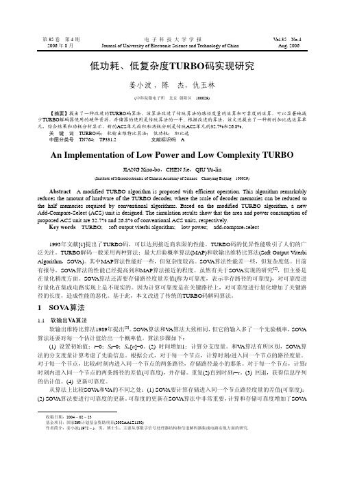
第35卷第4期电子科技大学学报V ol.35 No.42006年8月Journal of University of Electronic Science and Technology of China Aug. 2006 低功耗、低复杂度TURBO码实现研究姜小波,陈杰,仇玉林(中科院微电子所北京朝阳区 100029)【摘要】提出了一种改进的TURBO码算法,该算法改进了传统算法的路径度量的运算和可靠度的运算,可以显著地减少TURBO解码器使用的硬件资源,存储器的使用是传统算法的一半。
根据改进的算法,该文还提出了一种新的加比选运算单元,综合结果和功耗分析显示,新的ACS单元面积和功耗分别是传统ACS单元的32.7%和26.8%。
关键词TURBO码; 软输出维特比算法; 低功耗; 加比选中图分类号TN764; TP331.2文献标识码 AAn Implementation of Low Power and Low Complexity TURBOJIANG Xiao-bo,CHEN Jie,QIU Yu-lin(Institute of Microelectronics of Chinese Academy of Science Chaoyang Beijing 100029)Abstract A modified TURBO algorithm is proposed with efficient operation. This algorithm remarkably reduces the amount of hardware of the TURBO decoder, where the scale of decoder memories can be reduced to the half memories required by conventional algorithms. Based on the modified TURBO algorithm, a new Add-Compare-Select (ACS) unit is designed. The simulation results show that the area and power consumption of proposed ACS unit are 32.7% and 26.8% of conventional ACS units, respectively.Key words TURBO; soft output viterbi algorithm; low power; add-compare-select1993年文献[1]提出了TURBO码,可以达到接近商农限的性能。
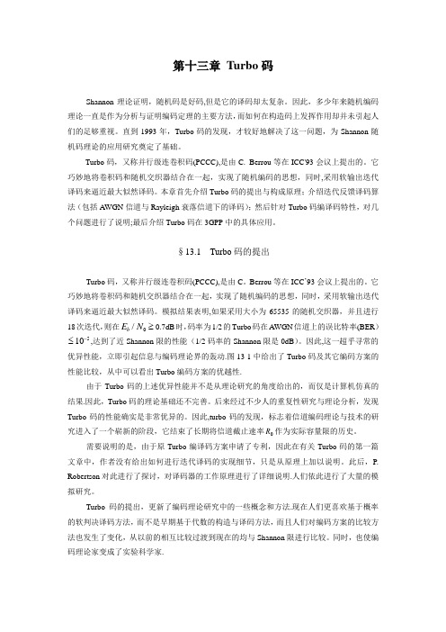
第十三章 Turbo 码Shannon 理论证明,随机码是好码,但是它的译码却太复杂。
因此,多少年来随机编码理论一直是作为分析与证明编码定理的主要方法,而如何在构造码上发挥作用却并未引起人们的足够重视。
直到1993年,Turbo 码的发现,才较好地解决了这一问题,为Shannon 随机码理论的应用研究奠定了基础。
Turbo 码,又称并行级连卷积码(PCCC),是由C. Berrou 等在ICC'93会议上提出的。
它巧妙地将卷积码和随机交织器结合在一起,实现了随机编码的思想,同时,采用软输出迭代译码来逼近最大似然译码。
本章首先介绍Turbo 码的提出与构成原理;介绍迭代反馈译码算法(包括AWGN 信道与Rayleigh 衰落信道下的译码);然后针对Turbo 码编译码特性,对几个问题进行了说明;最后介绍Turbo 码在3GPP 中的具体应用。
§13.1 Turbo 码的提出Turbo 码,又称并行级连卷积码(PCCC),是由C 。
Berrou 等在ICC ’93会议上提出的。
它巧妙地将卷积码和随机交织器结合在一起,实现了随机编码的思想,同时,采用软输出迭代译码来逼近最大似然译码。
模拟结果表明,如果采用大小为65535的随机交织器,并且进行18次迭代,则在E N b /0≥0.7dB 时,码率为1/2的Turbo 码在AWGN 信道上的误比特率(BER )≤-105,达到了近Shannon 限的性能(1/2码率的Shannon 限是0dB )。
因此,这一超乎寻常的优异性能,立即引起信息与编码理论界的轰动.图13-1中给出了Turbo 码及其它编码方案的性能比较,从中可以看出Turbo 编码方案的优越性.由于Turbo 码的上述优异性能并不是从理论研究的角度给出的,而仅是计算机仿真的结果.因此,Turbo 码的理论基础还不完善。
后来经过不少人的重复性研究与理论分析,发现Turbo 码的性能确实是非常优异的。
© Copyright 2012–2015 Xilinx, Inc. Xilinx, the Xilinx logo, Artix, ISE, Kintex, Spartan, Virtex, Vivado, Zynq, and other designated brands included herein are trademarks of Xilinx in the United States and other countries. All other trademarks are the property of their respective owners.IntroductionThe LogiCORE™ IP 3GPP Mixed Mode Turbo Decoder provides a flexible turbo convolutional decode function for both LTE and WCDMA air interfaces. The implementation is compliant with the requirements set out in both [Ref 1] and [Ref 2]. The core provides an optimized turbo decode function for base stations at all form factors, from femto to macrocells. The decoder, when used with a TCC encoder,provides an effective way of transmitting data reliably over noisy data channels.Additional DocumentationA full product guide is available for this core. Access to this material can be requested by clicking on this registration link:/member/mm_tcc_dec_eval/index.htmFeatures•Three versions of this core can be generated, each supporting different standard options:°LTE only °UMTS only °LTE and UMTS•When UMTS and LTE are both supported the core can switch between different standards on a block by block basis.•Each core is completely self contained, requiring nothing else to decode data.•All 3GPP LTE block sizes supported: 188 different block sizes in the range 40–6144•All 3GPP UMTS block sizes supported, that is block sizes in the range 40-5114.See Feature Summary for additional features.LogiCORE IP 3GPP Mixed ModeTurbo Decoder v2.0PB009 (v2.0) November 18, 2015Product BriefLogiCORE IP Facts TableCore SpecificsSupportedDevice Family (1)UltraScale+™ Families UltraScale ™ ArchitectureZynq®-7000 All Programmable SoC7 SeriesSupported User InterfacesAXI4-StreamProvided with CoreDesign Files Encypted RTLExample Design VHDL Test Bench VHDLConstraints File Not ProvidedSimulation Model Encrypted VHDLC Model and MATLAB® ModelSupported S/W DriverN/ATested Design Flows (2)Design Entry Vivado® Design SuiteSimulation For supported simulators, see theXilinx Design Tools: Release Notes Guide .SynthesisVivado SynthesisSupportProvided by Xilinx at the Xilinx Support web pageNotes:1.For a complete listing of supported devices, see the Vivado IPcatalog.2.For the supported versions of the tools, see theXilinx Design Tools: Release Notes Guide .Feature Summary•Configurable with either 1, 2, 4 or 8 decode units, allowing resource utilization to be optimized while meeting system performance requirements at all base station form factors.•Dynamically selectable number of iterations 1-15.•Support for MAX, MAX_SCALE and MAX_STAR algorithms.•AXI4-Stream interfaces used for control and data input/output.• C model and MATLAB MEX function available for bit accurate modelling of error correcting performance.•Number representation: Twos complement fractional.•Data Input: 7 or 8 bits (4 or 5 integer bits with 3 fractional bits)•Hardware DSP units can be used instead of logic resources to tailor the core resource usage to specific user applications.•Demonstration test bench to show an example of core usage.•Integrated scheduler ensures that decode latency remains virtually constant with variable block sizes.OverviewThe TCC decoder is used in conjunction with a TCC encoder to provide an effective way of transmitting data reliably over noisy data channels. The turbo decoder operates very well under low signal-to-noise conditions and provides a performance close to the theoretical optimal performance defined by the Shannon limit [Ref3].References1.3GPP TS 25.212 "Multiplexing and channel coding (FDD)", v10.1.02.3GPP TS 36.212 "Multiplexing and channel coding", v10.3.03. C. Berrou, A. Glavieux, and P. Thitimajshima, Near Shannon Limit Error-correcting Coding andDecoding Turbo Codes, IEEE Proc 1993 Int Conf. Comm., pp1064-1070Technical SupportXilinx provides technical support at the Xilinx Support web page for this LogiCORE™ IP product when used as described in the product documentation. Xilinx cannot guarantee timing, functionality, or support if you do any of the following:•Implement the solution in devices that are not defined in the documentation.•Customize the solution beyond that allowed in the product documentation.•Change any section of the design labeled DO NOT MODIFY.To contact Xilinx Technical Support, navigate to the Xilinx Support web page. Licensing and Ordering InformationThis Xilinx LogiCORE™ IP module is provided under the terms of the Xilinx Turbo Code LogiCORE IP License Terms.The module is shipped as part of the Vivado Design Suite. For full access to all core functionalities in simulation and in hardware, you must purchase a license for the core. Contact your local Xilinx sales representative for information about pricing and availability.For more information, visit the 3GPP Mixed Mode Turbo Decoder product page.Information about other Xilinx LogiCORE IP modules is available at the Xilinx Intellectual Property page. For information on pricing and availability of other Xilinx LogiCORE IP modules and tools, contact your local Xilinx sales representative.Disclaimer: France Telecom, for itself and certain other parties, claims certain intellectual property rights covering Turbo Codes technology, and has decided to license these rights under a licensing program called the Turbo Codes Licensing Program. Supply of this IP core does not convey a license nor imply any right to use any Turbo Codes patents owned by France Telecom, TDF or GET. Contact France Telecom for information about its Turbo Codes Licensing Program at the following address:France Telecom R&D,VAT/TURBOCODES,38, rue du Général Leclerc,92794 Issy Moulineaux,Cedex 9,France.Evaluation LicenseAn evaluation license is available for this core. The evaluation version of the core operates in the same way as the full version for several hours, depending on clock frequency. Operation is then disabled and the data output does not change. If you notice this behavior in hardware, it means that you are using an evaluation version of the core. The Xilinx tools warn that an evaluation license is being used during netlist implementation. If a full license is installed in order for the core to run on hardware, delete the old configuration file and re-create the core from new.Revision HistoryThe following table shows the revision history for this document:Please Read: Important Legal NoticesThe information disclosed to you hereunder (the “Materials”) is provided solely for the selection and use of Xilinx products. To the maximum extent permitted by applicable law: (1) Materials are made available “AS IS” and with all faults, Xilinx hereby DISCLAIMS ALL WARRANTIES AND CONDITIONS, EXPRESS, IMPLIED, OR STATUTORY, INCLUDING BUT NOT LIMITED TO WARRANTIES OF MERCHANTABILITY,NON-INFRINGEMENT, OR FITNESS FOR ANY PARTICULAR PURPOSE; and (2) Xilinx shall not be liable (whether in contract or tort, including negligence, or under any other theory of liability) for any loss or damage of any kind or nature related to, arising under, or in connection with, the Materials (including your use of the Materials), including for any direct, indirect, special, incidental, or consequential loss or damage (including loss of data, profits, goodwill, or any type of loss or damage suffered as a result of any action brought by a third party) even if such damage or loss was reasonably foreseeable or Xilinx had been advised of the possibility of the same. Xilinx assumes no obligation to correct any errors contained in the Materials or to notify you of updates to the Materials or to product specifications. You may not reproduce, modify, distribute, or publicly display the Materials without prior written consent. Certain products are subject to the terms and conditions of Xilinx's limited warranty, please refer to Xilinx's Terms of Sale which can be viewed at /legal.htm#tos ; IP cores may be subject to warranty and support terms contained in a license issued to you by Xilinx. Xilinx products are not designed or intended to be fail-safe or for use in any application requiring fail-safe performance; you assume sole risk and liability for use of Xilinx products in such critical applications, please refer to Xilinx's Terms of Sale which can be viewed at /legal.htm#tos .DateVersionDescription of Revisions11/18/2015 2.0UltraScale+ device support added.04/02/2014 2.0Characterization data added to PG030.12/18/2013 2.0Added UltraScale architecture support.03/20/2013 2.0Updated for Vivado design tools.01/18/20121.0Xilinx initial release.。
T urbo C 2. 0 编译错误信息编译错误信息Turbo C编译程序检查源程序中三类出错信息:致命错误、一般错误和警告。
致命错误出现很少,它通常是内部编译出错。
在发生错误时,立即停止,必须采取一些适当的措施并重新编译。
一般错误指程序的语法错误、磁盘或内存存取错误或命令错误等。
编译程序将根据事先庙宇的出错个数来决定是否停止编译。
编译程序在每个阶段(预处理、语法分析、优化、代码生成)尽可能多地发现源程序中的错误。
警告并不阻止编译进行。
它指出一些值得怀疑的情况,而这些情况本身又有可能合理地成为源程序的一部分。
如果在源文件中使用了与机器有关的结构,编译也将产生警告信息。
编译程序首先输出这三类错误信息,然后输出源文件名和发现出错的行号,最后输出信息的内容。
下面按字母顺序分别列出这三类错误信息。
对每一条信息,提供可能产生的原因和修正方法。
请注意错误信息处有关行事情的一个细节:编译程序只产生被检测到的信息。
因为C并不限定在正文的某行放一条语句,这样,真正产生错误的行可能在编译指出的前一行或几行。
在下面的信息列表中,我们指出了这种可能。
致命错误1. Bad call of in-line function 内部函数非法调用在使用一个宏定义的内部函数时,没有正确调用。
一个内部函数以双下划线(--)开始和结束。
2. Irreducible expression tree 不可约表达式树这种错误是由于源文件中的某些表达式使得代码生成程序无法为它产生代码。
这种表达式必须避免使用。
3. Register allocation failure 存储器分配失效这种错误指的是源文件行中的表达式太复杂,代码生成程序无法为它代码。
此时应简化这种繁杂的表达式或干脆避免使用它。
一般错误1. #operator not followed by macro argument name#运算符后无宏变量名。
在宏定义中,#用于标识一宏变量名。
Turbo Code Implementation Issues for Low Latency, Low Power ApplicationsD. Eric Cresscress@andWilliam J. Ebel, Member IEEEebel@Mississippi State UniversityElectrical and Computer EngineeringBox 9571Mississippi State, MS, 39762 USAAbstract: In this paper, four important and interrelated issues are discussed which relate to the performance of Turbo codes for low latency and low power applications: (1) interleaving, (2) trellis termination, (3) estimation of the channel noise variance, and (4) fixed point arithmetic effects on decoder performance. We give a method for terminating both constituent convolutional encoders in a known (all zero) state by assigning specific bits within the information sequence binary values that are dependent upon the user input information bits. This method causes a slight restriction on the set of allowable interleavers that can be chosen for the scheme but does not compromise performance. Also, we give a robust method for estimating the conditional channel variance given pre-thresholded random variable samples measured directly from the channel. Finally, performance results are shown for fixed-point number representations and arithmetic.A. IntroductionAn exciting development in recent years in the field of error correcting codes was the introduction of Turbo codes [1]. Empirical results indicate that these codes approach the Shannon limit for reliability improvement on an AWGN channel. In this paper, four important and interrelated issues are discussed which relate to the performance of Turbo codes for low latency and low power applications: (1) interleaving, (2) trellis termination, (3) estimation of the channel noise variance, and (4) fixed point arithmetic effects.A typical Turbo encoder is shown in Figure 1. The binary data sequence x is input to a raterecursive convolutional encoder (RCC) and at the same time it is input to an interleaver 12⁄which generates the output sequence y and subsequently input to a second RCC. The output consists of the original data along with the parity resulting from the two constituent convolutionalencoders.For the purposes of this discussion, the modulator is taken to be binary and is implemented by the mapping where z represents a transmitted symbol and x represents a binary number. In this way, a binary 1 maps to the real number 1 and a binary 0 maps to the real number -1. Therefore the transmitter power is per transmitted bit. The channel is taken to be AWGN and is implemented by adding a Gaussian random variable (RV) to each transmitted symbol. If is the variance of the added noise RV , then the signal-to-noise ratio (SNR) of the system is . The received sequences are given by ,, and, , where n 1, n 2, and n 3, are independent Gaussian noise sequences with variance . We will use primes to denote variables that have an added noise component.The parallel configuration of the encoder along with the systematic implementation of the convolutional encoders allows the decoder to operate in an iterative fashion. Figure 2 illustrates,in concept, a simplified Turbo decoder. First the received input sequence and the received parity sequence are paired and input to the first Maximum A-Posteriori (MAP) decoder [2][3].In concept, the output x is an estimate of the original input data in the form of a probability measure that each bit in the sequence is a binary “1”. The rest of the decoder operates as shown. Turbo codes have traditionally been shown to yield remarkable performance for long blocklengths (large interleaver), usually on the order of many tens of thousands of bits [4][5], i.e.... p 2, p 1, xFigure 1. Example Turbo encoder.z 2x 1–=P b 1=σ21σ2⁄x 'x n 1+=p '1p 1n 2+=p '2p 2n 3+=σ2x 'p '1to bits. The large interleaver is used to reduce the multiplicities of low weight codewords, known as spectral thinning [6], however it also plays an important secondary role in eliminating the effect of poor decoded-bit estimates caused by unknown or unreliable constituent convolutional encoder state terminations. To be more specific, the constituent convolutional encoders of a Turbo code are generally configured to be terminated using tail bits that are transmitted in addition to the data sequence and parity sequences. These tail bits do not benefit from the diversity effect of the interleaver in the iterative decoder and result in poor decoded bit estimates. To illustrate this, Figure 3 shows the number of errors that occurred per information bit position in the data sequence for a rate 1/3 Turbo code using 8-state recursive convolutional codes, an information sequence length of 30 bits, and with an SNR of 1.5dB. The algorithm using tail bits for trellis termination resulted in 8,262 bit errors out of 330,000 total bits. The algorithm using full interleaving with trellis termination, described in Section B below, resulted in 1,449 bit errors out of 300,000 total bits. The bulk of the additional errors resulted from the poor tail bit estimates and their residual effect on other bits. When large interleavers are used, these poor estimates have a negligible effect on the overall performance of the code.In wireless applications, however, the blocklengths are necessarily much smaller, on the order of a few hundred bits or less. The main issue in any practical solution is code performance per unit complexity of the hardware realization, especially in a commercial application involving handheld, battery-powered electronic devices. In Section B, we describe a method for terminating the constituent convolutional encoders to improve the performance in short blocklength105106Figure 2. Example Turbo decoder. Underscored variables denote estimates.12applications.In this paper, we also give a robust method for estimating the channel noise variance directly from the received data. This method is empirically shown to yield decoded error probability performance that is nearly identical to that which results when using the true value.Finally, we show fixed-point arithmetic results for Turbo decoders. If the hardware implementation of a Turbo decoder is not configured carefully, unstable behavior can be observed. We show that for some simple codes, as few as 4 bits of precision provide a reasonable coding gains suggesting an interesting trade-off between complexity and performance.B. Interleaving and Trellis TerminationIn this section, an algorithm is described as first suggested by Barbelescue [8], which terminates the trellis of the two constituent encoders by properly selecting the first 2m bits of the information sequence, where m is the number of delays in each constituent encoder. We call these first 2m bits precursor bits . A Turbo encoder using precursor bits for trellis termination is shown in Figure 4. The precursor bits are denoted by the length-2m sequence s . The encoder requires two passes. In the first pass, the precursor bits are set to zero and data is sequenced into the two constituent RCC’s without regard for the final state. After the data is input, the final state of the each encoder is sent to a ROM where the precursor bits are read out and positioned at theError Bit Position2004006008001000N u m b e r o f E r r o r O c c u r r e n c e sFigure 3. Turbo code performance for an 8-state RCC with SNR = 1.5dB.beginning of the input sequence. These precursor bits will guarantee that the two constituentRCC’s end up in the all zero state at the end of the second encoding pass. The ROM is stored off line by iterating through all possible precursor sequences s and storing the final encoder state for each RCC. Since the encoder is linear, the second pass will result in final RCC states which are the sum of the final state due to the data and the precursor bits. Since these final states are identical and the sum of two identical GF(2) numbers is always zero, this results in final RCC states that are zero.There is only one issue to contend with here. In order for this to work, the off-line procedure for building the ROM must result in a one-to-one correspondence between each precursor binary number and each of the possible states in the second RCC. It is possible that the random interleaver will position the precursor bits in y in such a way so that iterating through all possible precursor binary numbers does not result in an exhaustive set of final states for the second RCC.We say that such an interleaver is not proper. In our simulation, the random interleaver is reselected until a proper one is found. Each interleaver is checked to see if the set of possible precursor bits result in a duplicate encoder state for the second RCC. In our simulation, the21Figure 4. Turbo encoder with trellis termination using precursor bits.interleaver is generally reselected from 0 to 8 times before a proper one is found.In this configuration, the entire input sequence, including the precursor bits, is interleaved.This eliminates the bias in the error probability introduced by the non-interleaved trellis tail bits for trellis termination. Also note that the code rate for this configuration is which is approximately 1/3 for large N .The Turbo decoder corresponding to this Turbo encoder is shown in Figure 5. Thepermutation resulting from the interleaver and deinterleaver are identical to that used in the encoder except that the entries are real numbers rather than binary numbers.C. Channel Noise Variance EstimationIn this section, a method for estimating both the conditional mean and conditional variance for the received data which enters the Turbo decoder is described. The problem can be stated as follows. Let Z be a random variable (RV) with pdf given byR N 2m –3N -----------------=Figure 5. Turbo decoder which uses precursor bits for trellis termination.where is the Gaussian pdf with mean m , variance , and with independent variable z .The goal is to estimate the conditional statistics given only measured statistics of RV Z . An illustration of is shown in Figure 6. If is small, then an efficient method for computing m and is to find the mean and variance for the RV . The error caused by the tail overlap will be negligible. However, a more practical situation occurs when the conditional variance is large, corresponding to a low channel SNR. In this case, the parameters can be estimated by computing the 2nd and 4th moment of Z , denoted and , respectively. Since the mean of Z is zero, the second moment is.Each integral represents the second central moment of a Gaussian RV with mean m and variance and evaluates to the same expression, given byTherefore, the second moment of Z is(1)Since is directly measurable from a set of samples of Z , this gives one equation in terms of the unknowns m and . Similarly, the 4th moment of Z can be shown to be (2)f Z z ()12--g z m σ2,;()g z m –σ2,;()+[]=g z m σ2,;()σ2f Z z ()Figure 6. The bimodal pdf of the RV Z .m σ2⁄σ2Z m 2m 4m 2Var Z ()E Z 2{}-z 2g z m σ2,;()z d ∞∞∫z 2g z m –σ2,;()d ∞–∞∫+===σ2z 2g z m σ2,;()z d ∞–∞∫σ2m2+=m 2E Z 2{}σ2m2+==m 2σ2m 4E Z 4{}m 22σ2m 2+()2m 2σ2+==Solving (1) and (2) simultaneously, givesandOf course, since the measured moments are themselves RV’s, there is always a chance that thesecalculations will fail. Surely we must have and . If either of these conditions fail, which is most probable if is small, then the first method should be used to estimate m and . In Table I below, the true channel noise variance is compared with the estimate using the method outlined in this section. The code chosen has a blocklength of 100 bits and 10 blocks werecombined to form the variance estimate. As the SNR increases, the estimate smoothly converges to the true estimate. In any case, the estimate is close to the true SNR value above 0dB and there was no appreciable difference in the performance of the decoded error probability noted when the estimated variance was used in place of the true variance.D. Fixed-Point Arithmetic ResultsIn Table II below, some experimental results for a hardware realizable turbo coding system are shown. The system uses a log-likelihood ratio decoder to minimize the hardware complexity byTable I. Comparison of true and estimated channel noise variancemˆ=σˆ2m 2m ˆ2–=3m 22m 4>m 2mˆ2>m σ2⁄σ2reducing costly fixed-point divides and multiplies. The code used is an optimal convolutional code of memory order 2. The interleaver is a block length 100 pseudo-random interleaver. Data is presented for varying degrees of fixed-point precision. The coding gain that is presented is for a channel modeled with AWGN and a signal-to-noise ratio (Eb/No) of 1.76dB. Note that no data is given for a dynamic range of less than -7 to 8 because that is the minimum dynamic range required to get coding gain using this system with a channel signal/noise ratio of 1.76dB.Table II. Fixed-point arithmetic results of the Turbo decoding algorithm.E. ConclusionsIn this paper, four important and interrelated issues were discussed which relate to the performance of Turbo codes for low latency and low power applications: (1) interleaving, (2) trellis termination, (3) estimation of the channel noise variance, and (4) fixed point arithmetic effects on decoder performance. We described a method for terminating both constituent convolutional encoders in a known (all zero) and also gave a robust method for estimating theconditional channel variance given pre-thresholded random variable samples measured directly from the channel. Finally, performance results are shown for fixed-point number representations and arithmetic.Bibliography[1]Berrou, C., Glavieux, A., and Thitimajshima, P., “Near Shannon Limit Error-CorrectingCoding and Decoding: Turbo-Codes (1)”, International Communications Conference, Geneva Switzerland, 1993, pp. 1064-1070.[2]Bahl, L.R., Cocke, J., Jelinek, F., and Raviv, J., “Optimal Decoding of Linear Codes forMinimizing Symbol Error Rate”, IEEE Transactions on Information Theory, March 1974, pp.284-287.[3]Forney, G.D. Jr., “The Forward-Backward Algorithm”, in Proc. 34th Allerton Conf.Commun., Contr., Computing, Allerton, IL, Oct. 1996.[4]Divsalar, D., and Pollara, F., “On the Design of Turbo Codes”, JPL TDA Progress Report 42-123, JPL, November 15, 1995, pp. 99-121.[5]Divsalar, D., and Pollara, F., “Turbo Codes for Deep-Space Communications” TDA ProgressReport 42-120, JPL, February 15, 1995, pp. 29-39.[6]Perez, L.C., Seghers, J., and Costello, D.J., “A Distance Spectrum Interpretation of TurboCodes”, IEEE Transactions on Information Theory, V ol. 42, No. 6, November 1996, pp. 1698-1709.[7]Blackert, W.J., Hall, E.K., and Wilson, S.G., “Turbo code termination and interleaverconditions”, V ol. 31, No. 24, November 23, 1995, pp. 2082-2083.[8]Barbulescu, A.S., and Pietrobon, S.S., “Interleaver design for turbo codes”, ElectronicsLetters, V ol. 30, No. 25, December 8, 1994, pp. 2107-2108.。