ET-A1-D24(1)比例阀控制放大器说明书
- 格式:pdf
- 大小:1.63 MB
- 文档页数:4
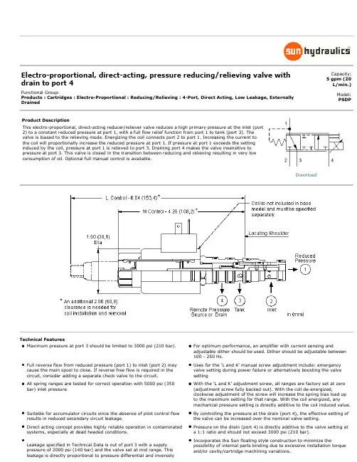
Electro-proportional, direct-acting, pressure reducing/relieving valve with drain to port 4Capacity: 5 gpm (20L/min.)Functional Group:Products : Cartridges : Electro-Proportional : Reducing/Relieving : 4-Port, Direct Acting, Low Leakage, Externally Drained Model: PSDPProduct DescriptionThis electro-proportional, direct-acting reducer/reliever valve reduces a high primary pressure at the inlet (port2) to a constant reduced pressure at port 1, with a full flow relief function from port 1 to tank (port 3). Thevalve is biased to the relieving mode. Energizing the coil connects port 2 to port 1. Increasing the current tothe coil will proportionally increase the reduced pressure at port 1. If pressure at port 1 exceeds the settinginduced by the coil, pressure at port 1 is relieved to port 3. Draining port 4 makes the valve insensitive topressure at port 3. This valve is closed in the transition between reducing and relieving resulting in very lowconsumption of oil. Optional full manual control is available.Technical FeaturesMaximum pressure at port 3 should be limited to 3000 psi (210 bar). For optimum performance, an amplifier with current sensing andadjustable dither should be used. Dither should be adjustable between100 - 250 Hz.Full reverse flow from reduced pressure (port 1) to inlet (port 2) may cause the main spool to close. If reverse free flow is required in the circuit, consider adding a separate check valve to the circuit. Uses for the 'L and K' manual screw adjustment include: emergency valve setting during power failure or alternatively boosting the valve settingAll spring ranges are tested for correct operation with 5000 psi (350 bar) inlet pressure. With the 'L and K' adjustment screw, all ranges are factory set at zero (adjustment screw fully backed out). With the coil de-energized, clockwise adjustment of the screw will increase the spring bias load up to the maximum setting for that range. With the coil energized, any mechanical pressure setting is directly additive to the coil induced value.Suitable for accumulator circuits since the absence of pilot control flow results in reduced secondary circuit leakage. By controlling the pressure at the drain (port 4), the effective setting of the valve can be increased over the nominal valve setting.Direct acting concept provides highly reliable operation in contaminated systems, especially at dead headed conditions. Pressure on the drain (port 4) is directly additive to the valve setting at a 1:1 ratio and should not exceed 3000 psi (210 bar).Leakage specified in Technical Data is out of port 3 with a supply pressure of 2000 psi (140 bar) and the valve set at mid range. This leakage is directly proportional to pressure differential and inversely Incorporates the Sun floating style construction to minimize the possibility of internal parts binding due to excessive installation torqueand/or cavity/cartridge machining variations.Downloadproportional to viscosity expressed in centistokes.The transition from reducing to relieving is closed. The result is very low leakage. However, there is a transitional step increase in pressure between reducing and relieving modes. This step equals about 5% ofthe high end of the adjustment range, independent of the valve setting.PSDP-MDN-***Control Operating Range Seal Material CoilStandard OptionsL Standard Screw Adjustment M Manual Override (Standard) Standard OptionsB100 - 1200 psi (7 - 80 bar)D50 - 500 psi (3,5 - 35 bar)E25 - 250 psi (1,7 - 18 bar)Standard OptionsN Buna-NV Viton***See Coil Options BelowStandard Coil Options (View All)DIN 43650 3 pin(Hirschman)SAE J858A AMP Junior Timer Twin Lead Metri-Pack Deutsch DT04-2P *** no coil 612AMP Junior Timer 12 VDC 812Metri-Pack 12 VDC212DIN 43650 3 pin(Hirschman) 12 VDC624AMP Junior Timer 24 VDC 824Metri-Pack 24 VDC224DIN 43650 3 pin(Hirschman) 24 VDC712Twin Lead 12 VDC 912Deutsch DT04-2P 12 VDC524SAE J858A 24 VDC 724Twin Lead 24 VDC 924Deutsch DT04-2P 24 VDC Embedded Coil Options (Click Here)2B12A DIN 43650 3 pin(Hirschman) commandcommon on fourth pin 12VDC 0-20 mA 2C24V DIN 43650 3 pin(Hirschman) +5V referenceon fourth pin 24 VDC 0-10V4A12A Deutsch DT04-6P allfunctions enabled (separatecommand common, 5 vreference, and an enable) 12VDC 0-20 mA2B12V DIN 43650 3 pin(Hirschman) commandcommon on fourth pin 12VDC 0-10V 2D12A DIN 43650 3 pin(Hirschman) enable input onfourth pin 12 VDC 0-20 mA4A12V Deutsch DT04-6P allfunctions enabled (separatecommand common, 5 vreference, and an enable) 12VDC 0-10V2B24A DIN 43650 3 pin(Hirschman) commandcommon on fourth pin 24VDC 0-20 mA 2D12V DIN 43650 3 pin(Hirschman) enable input onfourth pin 12 VDC 0-10V4A24A Deutsch DT04-6P allfunctions enabled (separatecommand common, 5 vreference, and an enable) 24VDC 0-20 mA2B24V DIN 43650 3 pin(Hirschman) commandcommon on fourth pin 24VDC 0-10V 2D24A DIN 43650 3 pin(Hirschman) enable input onfourth pin 24 VDC 0-20 mA4A24V Deutsch DT04-6P allfunctions enabled (separatecommand common, 5 vreference, and an enable) 24VDC 0-10V2C12A DIN 43650 3 pin(Hirschman) +5V referenceon fourth pin 12 VDC 0-20mA 2D24V DIN 43650 3 pin(Hirschman) enable input onfourth pin 24 VDC 0-10V4F12V Deutsch DT04-6Pprogrammable ramps,separate rise and fall 12VDC 0-10V2C12V DIN 43650 3 pin(Hirschman) +5V referenceon fourth pin 12 VDC 0-10V 2F12V DIN 43650 3 pin(Hirschman) programmableramps, separate rise and fall12 VDC 0-10V4F24V Deutsch DT04-6Pprogrammable ramps,separate rise and fall 24VDC 0-10V2C24A DIN 43650 3 pin(Hirschman) +5V referenceon fourth pin 24 VDC 0-20mA 2F24V DIN 43650 3 pin(Hirschman) programmableramps, separate rise and fall24 VDC 0-10VAdditional Options (Click Here)Additional Coils512SAE J858A 12 VDCStainless options not available for this modelCopyright © 2002-2012 Sun Hydraulics Corporation. All rights reserved.Terms and Conditions - ISO Certification - Statement of Privacy。
1关于本文件1.1适用文件1.2产品标记–请注意产品上的说明。
警告标志产品上有下列警告标志:2安全2.1安全注意事项–仅在原装状态下使用产品,请勿擅自进行改动。
–请仅在技术状态完好且未损坏的情况下使用本产品。
–请注意使用场所的环境条件。
–在产品上作业前:关断电源,并做好防重启保护。
–安装产品,确保只有授权人员才能使用。
–请注意章节 è 7 安装 中更多与安全相关的提示。
2.2按规定使用该产品按规定用于根据给定的额定值按比例调节压力。
本产品设计用于工业领域。
3其他信息–技术问题请联系当地 Festo 联络人 è .–附件和备件 è /catalogue。
4产品概况4.1功能原理集成式压力传感器可感测到工作接口的压力,并将其与额定值进行比较。
在实际值和设定点值之间存在偏差时,阀将进行调节,直到输出压力达到设定点值。
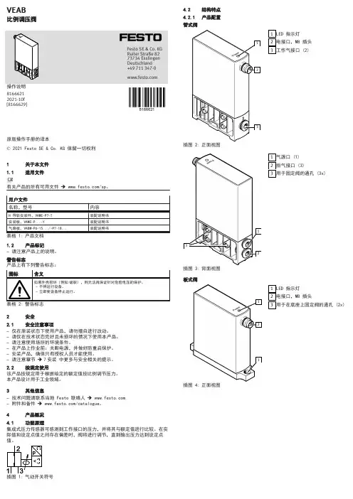
4.2结构特点4.2.1产品配置管式阀插图 2:正面视图插图 3:背面视图板式阀插图 4:正面视图插图 5:底部视图4.2.2产品派生型5运输和存放–在干燥、防紫外线、防腐蚀的环境中存放本产品。
–确保短期存放。
6机械安装1.注意为连接电缆和气管接口留出足够的空间。
Ä如此即可避免连接电缆和气管扭结。
2.请将阀安放在负载设备附近。
Ä这样可以达到更好的控制精度和更短的响应时间。
阀固定方式:–通过侧面的 3 个通孔穿透固定管式阀–通过高帽式导轨安装件 VAME-P7-T 将管式阀固定在高帽式导轨上 è 1.1 适用文件–将管式阀固定在安装板 VAME-P7-Y 上 è 1.1 适用文件–使用气路板 VABM-.... 的 2 个通孔固定板式阀 è 1.1 适用文件7安装7.1气动部分安装(管式阀)用于标准运行模式的阀(超压)1.请为以下接口接上气管:–气源口 (1)–工作气接口 (2)2.请在排气接口 (3) 位置上安装一个消声器或通过接管的方式排气。
1/8模拟放大器类型 VT-VRPA1-50 至 VT-VRPA1-521X 系列RC 30117/07.06替代对象:05.06目录内容 页码特点 1订货代码 2功能说明2 - 3电路框图/插脚分配 4技术数据 5 - 6单元尺寸 6指示/调节元件7工程/维护注意事项/补充信息8特点– 适用于控制带有电气位置反馈的先导式比例流量控制阀(节流阀),类型 FE(规格 16 和 25)和 FES(规格 25 至 63)– 在插头方面,兼容放大器类型 VT 5011,VT 5012 和 VT 5062 至 VT 5066(视阀类型和规格而定)– 带可提高零电位的供电设备– 控制值信号输入:• 0 至 +6 V;0 至 +9 V;0 至 +10 V • 0 至 20 mA;4 至 20 mA(跳线)– 前面板上用于实现零电位和振幅衰减的电位计调节 – 斜坡时间的测量插口– 选通输入和"斜坡关闭"输入– 用于将最大斜坡时间从 0.02 s 更改至 5 s 或从 0.2 s 更改至 50 s 的跳线– 用于调整阀类型和规格的跳线– 控制值(0 至 +6 V)和实际值(0 至 –6 V)的输出– LED 指示灯"准备就绪"– 反向极性保护H6197_d订货代码用于带电气位置反馈的比例阀的模拟放大器,带1 个输出级用于以下比例流量控制阀(节流阀)的放大器:– 类型 FE 16,FE 25 和 FES 25(各类型均自系列 2X 起) = 50– 类型 FES 32 和 FES 40(各类型均自系列 3X 起) = 51– 类型 FES 50 和 FES 63(各类型均自系列 3X 起) = 52明文形式的更多详细信息1X =10 至 19 系列(10 至 19:技术数据和插脚分配不变)VT-VRPA11X*订购用于机架安装的 VT 5011,VT 5012 和 VT 5062 至 VT 5066 放大器备件时,盲板 4TE/3HE 必须单独订购。
比例阀的调整说明比例阀是工业自动化过程中常用的一种控制阀,它的主要用途是调节流体介质的流量和压力,使得流体系统能够按照预定的比例工作,从而实现对工业过程参数的精确调控。
下面是比例阀的调整说明。
1.准备工作:在进行比例阀的调整前,需要先进行准确的参数设定。
这包括需要调整的流量、压力范围以及所需的精度等。
同时,还需要了解控制系统的工作原理和控制模式。
2.比例阀的调整步骤:(1)将比例阀安装到系统中,并正确连接好进出口管线。
(2)调整比例阀的调节参数,比如开度范围、零点漂移、灵敏度等。
这些参数通常可以通过阀体上的调节螺丝来进行微调,具体调整方法需要查看比例阀的说明书。
(3)进行初步调试。
打开系统控制开关,观察比例阀的实际工作情况,检查是否存在异常情况。
(4)根据系统的要求,对比例阀的调节范围进行进一步调整。
比例阀的调节范围是指阀门的最小和最大开度之间的比例关系,调整范围越大,阀门的控制精度就越高。
(5)进行性能测试。
将比例阀置于工作状态下,通过外部信号调节阀门的开度,观察管道中介质的流量和压力变化,检查比例阀的控制精度是否满足要求。
3.比例阀的故障排除:在进行比例阀的调整过程中,如果出现工作不正常的情况,需要进行故障排除。
常见的比例阀故障包括阀门无法开启或关闭、阀门卡死、阀门漏气等。
故障排除的方法通常包括以下几个步骤:(1)检查比例阀的电源是否正常,电压是否稳定。
(2)检查阀门是否受到堵塞或损坏,是否需要进行清洗或更换部件。
(3)检查比例阀所处的管线是否存在压力异常或泄漏现象,必要时需要修复或更换管线。
(4)通过仪器检测比例阀的开度和闭合情况,观察是否存在异常。
4.比例阀的维护与保养:为了确保比例阀的正常工作,需要进行定期的维护与保养。
具体包括:(1)清洗比例阀,去除积聚在阀门表面的污垢或杂质。
(2)定期检查比例阀的阀门动作是否灵活,需要加油或更换易损部件。
(3)检查比例阀的电源连接是否良好,电压是否稳定。
比例阀调节参数说明
•1.蒸汽比例调节临界温度差:为防止进入杀菌阶段后温度过冲,在升温最后阶段实时温度接近设定温度时,蒸汽阀开始比例减小,此参数即用于设定实际温度与设定温度的差多少摄氏度时开始进入蒸汽比例阀比例减小阶段;
•2.升温时蒸汽阀系数:升温初阶段蒸汽阀开启系数,1为最大,0为不开;
•3.升温临界蒸汽阀系数:进入升温临界时,蒸汽阀开启系数,1为最大,0为不开;
•4.杀菌临界蒸汽阀系数:杀菌阶段蒸汽阀开启系数,1为最大,0为不开;
•5.升温临界蒸汽阀补偿:升温临界最后阶段比例阀减小至基本不开启状态,而此时产品吸收热量,导致进蒸汽量不足,温度迟迟难以达到杀菌设定温度,因而不能转换到杀菌步,该参数即用于杀菌临界最后阶段补偿蒸汽阀开启量,其大小应小于“蒸汽比例调节临界温度差”的值,常设定为“蒸汽比例调节临界温度差”值的1/2大小;
•6.杀菌临界蒸汽阀补偿:杀菌阶段为防止蒸汽比例阀开启量太小,给予蒸汽比例阀开启量补偿,其大小应小于“蒸汽比例调节临界温度差”的值,常设定为“蒸汽比例调节临界温度差”值的1/2大小;
•升温初阶段:蒸汽阀实际开启量=升温时蒸汽阀系数×蒸汽阀最大开启量;
•升温临界阶段:蒸汽阀实际开启量=升温临界蒸汽阀系数×【(设定温度-实际温度+升温临界蒸汽阀补偿)/蒸汽比例阀调节临界温度差】×蒸汽阀最大开启量;
•杀菌阶段:蒸汽阀实际开启量=升温临界蒸汽阀系数×【(设定温度-实际温度+杀菌临界蒸汽阀补偿)/蒸汽比例阀调节临界温度差】×蒸汽阀最大开启量。
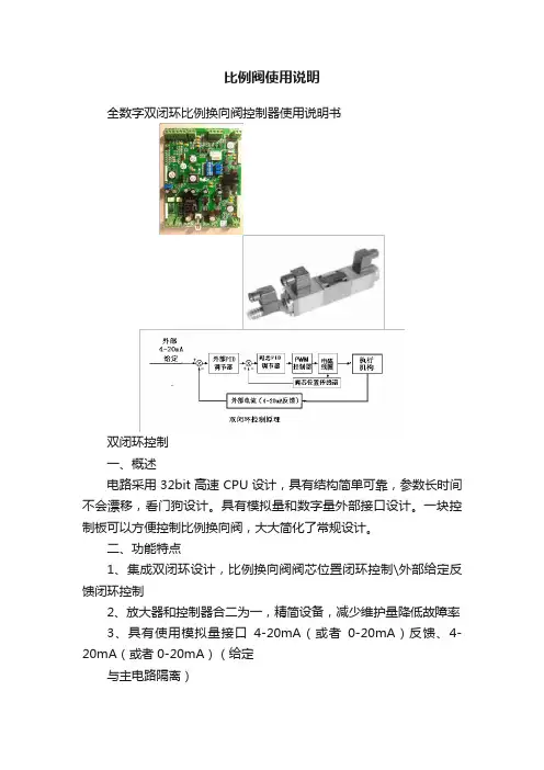
比例阀使用说明全数字双闭环比例换向阀控制器使用说明书双闭环控制一、概述电路采用32bit高速CPU设计,具有结构简单可靠,参数长时间不会漂移,看门狗设计。
具有模拟量和数字量外部接口设计。
一块控制板可以方便控制比例换向阀,大大简化了常规设计。
二、功能特点1、集成双闭环设计,比例换向阀阀芯位置闭环控制\外部给定反馈闭环控制2、放大器和控制器合二为一,精简设备,减少维护量降低故障率3、具有使用模拟量接口4-20mA(或者0-20mA)反馈、4-20mA(或者0-20mA)(给定与主电路隔离)4、具有数字量接口设计,MODEBUSRS485RTU、CANBUS接口5、可以多个设备进行组网控制,适合多点集中控制6、外部给定反馈闭环控制PID参数调节通过3个电位器调整7、两路阀芯电磁铁控制具有输出过流保护8、看门狗设计,能够及时复位异常工况三、参数1、供电:DC15~30VDC @ 2A2、尺寸123(mm)X160(mm)3、调节精度±1%4、适用范围:华德比例换向阀6通径或10通径带阀芯位置反馈装置进行液压缸、液压缸伸缩位置定位控制,马达行走机构定位控制,液压升降机构定位控制,液压紧紧力装置控制、液压马达行走速度控制等5、工作温度:-30~60摄氏度6、湿度:7、震动:四、典型应用执行机构可以是液压缸,液压马达等执行部件,可以对控制对象进行精准控制五、接线说明六、调整方法此步骤为出厂已经调试好,一般用户无需调整,如果参数确实差异很大,请谨慎操作1、按照接线方法接好线,并认真检查正确后,将控制板上的保险丝去掉,控制板上电后,用万用表的交流档测量COM与L 和COM与R的电压应相同大约在2.3VAC,如果差异大(>0.1VAC)就需要松开位置传感器上的螺丝,将位置传感器的位置通过两个限位螺丝移动,直到测量COM与L 和COM与R的电压应相同为止。
这个步骤一般用户只做检查即可,已经出厂调整过。
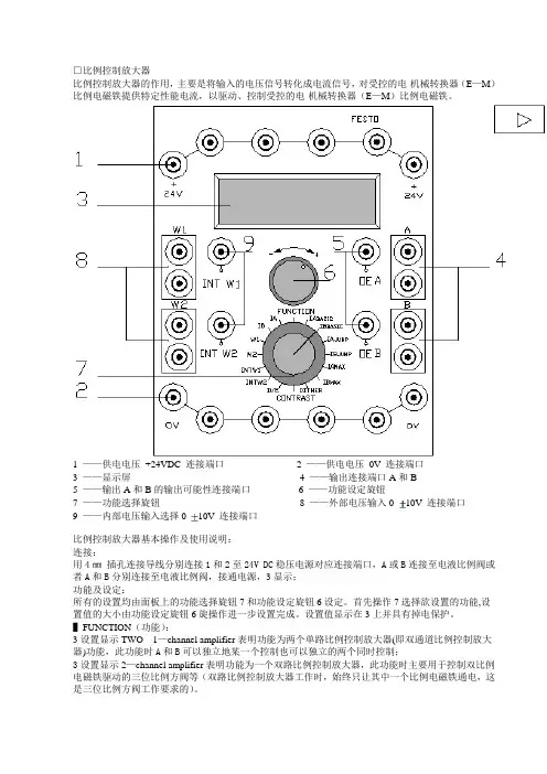
□比例控制放大器比例控制放大器的作用,主要是将输入的电压信号转化成电流信号,对受控的电-机械转换器(E—M)比例电磁铁提供特定性能电流,以驱动、控制受控的电-机械转换器(E—M)比例电磁铁。
1 ——供电电压+24VDC 连接端口2 ——供电电压0V 连接端口3 ——显示屏4 ——输出连接端口A和B5 ——输出A和B的输出可能性连接端口6 ——功能设定旋钮7 ——功能选择旋钮8 ——外部电压输入0 10V 连接端口9 ——内部电压输入选择010V 连接端口比例控制放大器基本操作及使用说明:连接:用4㎜插孔连接导线分别连接1和2至24V DC稳压电源对应连接端口,A或B连接至电液比例阀或者A和B分别连接至电液比例阀,接通电源,3显示;功能及设定:所有的设置均由面板上的功能选择旋钮7和功能设定旋钮6设定。
首先操作7选择欲设置的功能,设置值的大小由功能设定旋钮6旋操作进一步设置完成。
设置值显示在3上并具有掉电保护。
▌FUNCTION(功能):3设置显示TWO 1—channel amplifier表明功能为两个单路比例控制放大器(即双通道比例控制放大器)功能,此功能时A和B可以独立地某一个控制也可以独立的两个同时控制;3设置显示2—channel amplifier表明功能为一个双路比例控制放大器,此功能时主要用于控制双比例电磁铁驱动的三位比例方阀等(双路比例控制放大器工作时,始终只让其中一个比例电磁铁通电,这是三位比例方阀工作要求的)。
▌IA BASIC IB BASIC(A端口起始电流B端口起始电流) 设置A B连接端口起始电流。
▌IA JUMP IB JUMP (A端口阶跃电流B端口阶跃电流) 设置A B连接端口阶跃电流。
▌IA MAX IB MAX (A端口最大电流B端口最大电流) 设置A B连接端口最大电流。
▌DITHER(颤振) 设置颤振频率,设置的频率适用于比例控制放大器控制的一个或两个比例电磁铁。

U P rogrammable Direct or Reverse Acting Control U P recision Control Is Achieved Via 10-Bit Converter Controlling 200 Step Per Revolution Motor U R ugged Construction for Industrial Applications U E xternal SafetyOverride Contacts to Open/Close Valve U N EMA 4 (IP66) Rating for Outdoor Use U I deal for Liquid and Gas ApplicationsAn electronically controlledproportioning valve (ECV) will take an electrical input signal (usually 4 to 20 mA) and proportion the amount of flow through a pipe from fully closed to fully open. The Omega TM ECV valve features programmable reverse or directacting control. “Direct acting” means that, as the current signal rises, the valve allows more flow, while “reverse acting” will decrease the flow rate with an increasing current signal.These units can also beprogrammed to sense failures in the current loop and fully close or open the valve upon the signal level’s dropping below 4.0 mA. Dry contact remote switches can be used in conjunction with thestandard current signal to provide an alarm signal which fully closes or opens the valve. An internal 5 Vdc signal is used to sense the state of the external switches.ELECTRONICALLY CONTROLLED PROPORTIONING VALVESPV14-BARTWORK/MECH ART/ Pressure C-29The rugged epoxy- coated aluminum package insures NEMA 4X (IP66)protection the powerful microprocessor and servoactuator. Internally, a 10-bit A/Dconverter positions a 200 step/revolution stepper motor for precise flow. The stepper motor is directlyconnected to the valve stem without gearing, thereby eliminating backlash (hysteresis) effects.The valve can also be manually controlled with a screwdriver.Available with brass or stainless steel body.PV14-B shownsmaller than actual size.ACTUATOR Type: DC step motor, 200 steps/rev, 4 rev travel Resolution: 200:1 (0.5%) (4 steps increment)Speed: 18 rpmTorque: 57.5 in-oz (188 in-oz 3⁄4" valve)VALVEType: In-line globeTemperature: -18 to 121°C (0 to 250°F)Pressure: 120 psi maximum (70 psi on 3⁄4" valve)Maximum Flow: GPM = Cv (∆P/SG).5 liquids; for gases use standard equation found in solenoid valve sectionWetted Parts: Ethylene propylene rubber O-ring, PTFE washer, and valve body (Brass models have 303 SS internal trim)COMPLETE UNITDimensions: 216 H x 185 W x 137 mm D (8.5 x 7.3 x 5.4")1⁄2" Valve: 229 H x 185 W x 137 mm D (9 x 7.3 x 5.4")3⁄4" Valve: 305 H x 203 W x 191 mm D(12 x 8 x 7.5")Weight: 3.2 kg (7 lb) 1⁄2" Valve: 4.5 kg (10 lb) 3⁄4" Valve: 8.2 kg (18 lb)SPECIFICATIONSElectronicsPower Supply: 12 to 24 Vdc @ 5 A (10 W typical, 23 W maximum)(2.5 A for 3⁄4" valve, 38 W maximum)Inputs: 4 to 20 mA control signal (250 Ω impedance) and dual external switch contact sensing via 5 Vdc signal Control Modes: Direct or reverse, full or split range, high or low range, fail condition open or closed Adjustments: NoneOperating Temperature: 0 to 49°C (32 to 120°F)Enclosure: NEMA 4X (IP66), epoxy painted aluminumConnections: 1⁄2 NPT conduit (16" 22 AWG pigtail leads)Ordering Examples: PV14-B, 4 GPM brass proportioning valve.PV38-B, 12 GPM brass proportioning valve.PV14-SS(with cover removed), shown smaller than actual size.。
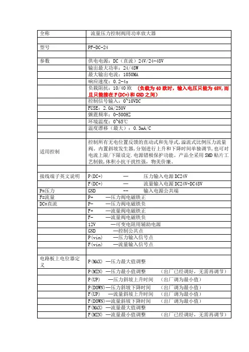
型號閥名稱功 能 模 型DC 電源輸入輸出功率(最大)負 載 阻 抗最大輸出電流VT-PF-D24-V壓力(P)直流輸入型24VDC 24W 10歐1000mA0.1s-5s控制信號輸入環 境 溫 度溫度漂移(最大)儲 藏 溫 度0~+10VDC 0.1s-5s800mA40歐48W 0~+10VDC 2.5A2.5AFUSE0~75℃0.3mA/℃-10~75℃流量(F)參數Power Amplifiers For Pressure & Flow Control Valves壓力.流量控制閥用功率放大器VT-PF-D24-V(1)响 应 速 度安 装 方 式轨道卡式單位:mm*以上說明,"F"代表"流量","P"代表壓力,F (UP )爲流量上升低斜率F (DOWN )爲流量下降低斜率,F (MAX )爲流量最大值,F (MIN )爲 流量最小值,以此類推图例VT-PF-D24-V(2)流量比例閥線圈壓力比例閥線圈+24+24GND GND+-A比流閥SOL直流電流錶(DC1A)(2)可變電阻(4.7-10K)手動旋轉控制(1)模拟量模块D/A輸出控制1、配線方式:如上圖示,建議如下:1)電流錶配線如上圖例,選擇1安培直流電流錶(1A,DC)壓力若不裝電流錶,則以壓力錶作爲調整的依據强烈建議流量的調整一定裝電流錶,以作爲調整依據2)控制訊號輸入僅列出常用兩種方式,僅能選擇其中一種方式做控制:(1)直接由控制器輸出0~10VDC做控制(2)使用可變電阻,連接板子上+12V輸出做控制2、調整步驟:(一)最小直調整(MIN):當控制訊號輸出爲0V時,調整至所需的起始电流值.(順時針調整,輸出增加)(二)最大值調整(MAX):當控制訊號輸出爲10V時,調整至所需要的最大电流值.(順時針調整,輸出增加,可變電阻調整時,可調到12V)(三)上升斜率調整(UP):順時針調整,上升時間短,反應速度快逆時針調整,上升時間長,反應速度慢(四)下降斜率調整(DOWN)順時針調整,下降時間短,反應速度快逆時針調整,下降時間長,反應速度慢注: 因在调整最大值与最小值调整时,两者存在相互较小的牵引作用,所以需反复校正一两次各自的值,建议在调整时,先校正起始值,然后调整最大值,之后再核实一次图例VT-PF-D24-V(3)。
Doc. no. VEP-OMM0002-CElectro-pneumatic proportional valveVEP/VEF/VEA/VER SeriesSafety Instructions ---------------------------------------------------------------------------------- 2,3 Design / Selection ------------------------------------------------------------------------------------- 4 Mounting ----------------------------------------------------------------------------------------------- 4 Piping --------------------------------------------------------------------------------------------------- 4 Lubrication --------------------------------------------------------------------------------------------- 5Air Supply ---------------------------------------------------------------------------------------------- 5 Operating Environment ----------------------------------------------------------------------------- 6 Maintenance ------------------------------------------------------------------------------------------- 6 Specific Product Precautions ---------------------------------------------------------------------- 7 to 14 Trouble shooting -------------------------------------------------------------------------------------- 15Safety InstructionsThese safety instructions are intended to prevent hazardous situations and/or equipment damage.These instructions indicate the level of potential hazard with the labels of “Caution,” “Warning” or “Danger.” They are all important notes for safety and must be followed in addition to International Standards (ISO/IEC)*1) , and other safety regulations.*1) ISO 4414: Pneumatic fluid power -- General rules relating to systems. ISO 4413: Hydraulic fluid power -- General rules relating to systems.IEC 60204-1: Safety of machinery -- Electrical equipment of machines .(Part 1: General requirements)ISO 10218-1992: Manipulating industrial robots -Safety. etc.Caution Caution indicates a hazard with a low level of risk which, if not avoided, could resultin minor or moderate injury.Warning Warning indicates a hazard with a medium level of risk which, if not avoided, could result in death or serious injury.DangerDanger indicates a hazard with a high level of risk which, if not avoided, will resultin death or serious injury.Warning 1. The compatibility of the product is the responsibility of the person who designs the equipment ordecides its specifications.Since the product specified here is used under various operating conditions, its compatibility with specific equipment must be decided by the person who designs the equipment or decides its specifications based on necessary analysis and test results.The expected performance and safety assurance of the equipment will be the responsibility of the person who has determined its compatibility with the product.This person should also continuously review all specifications of the product referring to its latest catalog information, with a view to giving due consideration to any possibility of equipment failure when configuring the equipment.2. Only personnel with appropriate training should operate machinery and equipment.The product specified here may become unsafe if handled incorrectly.The assembly, operation and maintenance of machines or equipment including our products must be performed by an operator who is appropriately trained and experienced.3. Do not service or attempt to remove product and machinery/equipment until safety is confirmed.1.The inspection and maintenance of machinery/equipment should only be performed after measures to prevent falling or runaway of the driven objects have been confirmed.2.When the product is to be removed, confirm that the safety measures as mentioned above are implemented and the power from any appropriate source is cut, and read and understand the specific product precautions of all relevant products carefully.3. Before machinery/equipment is restarted, take measures to prevent unexpected operation and malfunction.4. Contact SMC beforehand and take special consideration of safety measures if the product is to be used in any of the following conditions.1. Conditions and environments outside of the given specifications, or use outdoors or in a place exposed to direct sunlight.2. Installation on equipment in conjunction with atomic energy, railways, air navigation, space, shipping, vehicles, military, medical treatment, combustion and recreation, or equipment in contact with food and beverages, emergency stop circuits, clutch and brake circuits in press applications, safety equipment or other applications unsuitable for the standard specifications described in the product catalog.3. An application which could have negative effects on people, property, or animals requiring special safety analysis.e in an interlock circuit, which requires the provision of double interlock for possible failure by using a mechanical protective function, and periodical checks to confirm proper operation.- 2 -Safety InstructionsCaution1.The product is provided for use in manufacturing industries.The product herein described is basically provided for peaceful use in manufacturing industries.If considering using the product in other industries, consult SMC beforehand and exchange specifications or a contract if necessary.If anything is unclear, contact your nearest sales branch.Limited warranty and Disclaimer/Compliance RequirementsThe product used is subject to the following “Limited warranty and Disclaimer” and “Compliance Requirements”.Read and accept them before using the product.Limited warranty and Disclaimer1.The warranty period of the product is 1 year in service or 1.5 years after the product is delivered,whichever is first.∗2)Also, the product may have specified durability, running distance or replacement parts. Please consult your nearest sales branch.2. For any failure or damage reported within the warranty period which is clearly our responsibility,a replacement product or necessary parts will be provided.This limited warranty applies only to our product independently, and not to any other damage incurred due to the failure of the product.3. Prior to using SMC products, please read and understand the warranty terms and disclaimers noted in the specified catalog for the particular products.∗2) Vacuum pads are excluded from this 1 year warranty.A vacuum pad is a consumable part, so it is warranted for a year after it is delivered.Also, even within the warranty period, the wear of a product due to the use of the vacuumpad or failure due to the deterioration of rubber material are not covered by the limitedwarranty.Compliance Requirements1. The use of SMC products with production equipment for the manufacture of weapons of massdestruction(WMD) or any other weapon is strictly prohibited.2. The exports of SMC products or technology from one country to another are govemed by therelevant security laws and regulation of the countries involved in the transaction. Prior to the shipment of a SMC product to another country, assure that all local rules goveming that export ollowed.are known and f ollowed.- 3 -1. Confirm the specifications.Products represented in this manual are designed only for use in compressed air systems.Do not operate at pressures or temperatures, etc., beyond the1. Operation in a low temperature conditionIt is possible to operate a electro-pneumatic proportional valve in extrememeasures to avoid freezing of drainage, moisture etc., in low 1. Operation manualInstalloperationAlso, 1. Preparation before pipingBefore piping is connected, it should be thoroughly blown out with air (flushing) or washed to remove chips, cutting oil and other debris from inside the pipe.the end of the threads.3. Preparation after piping1. The electro-pneumatic proportional valve has been lubricated for lifeservice.2. If a lubricant is used in the system, use turbine oil class 1 (no 1. Type of fluidsPleaseapplications other than compressed air.2. When there is a large amount of drainage.1. WheninsidereliabilityPlease avoid using the extremely dry air. 4. Ifseparatorpneumatic proportional valve.If excessiveCaution1. Do electro-pneumatic contact1. Perform procedures indicated in the operation manual. If handled improperly, malfunction and damage of machinery Maintenance1. Drain flushing Remove drainage from the air filters regularly.2. LubricationBe sure to continue to supply lubricant once it has been started.And, use turbine oil Class 1 (with no additive) ISO VG32 for lubrication.If other lubricant oil is used, it may cause malfunction.VEA250 SeriesVEF ・ VEP Series VER SeriesCautionCaution1. Vibrations caused by proportional solenoid valve oscillation are transmitted to the transmission of vibration rubber material before installation.2. Flush the piping to thoroughly remove any dust or scale from inside of the piping before connecting it.3. Mount a silencer (AN series) on the exhaust port.4. Handle the molded while energized.5. Mount the EP proportional mounted horizontally.To check without applying power, remove the rubber cap and press the tip of the core with a screwdriver. After checking the operation, reinstall the rubber cap in its original position.Wiring procedure1. Loosen the holding screw and pull the connector out of the pin plug.2. Make sure to remove the holding screw, insert the tip of a flat3. Put the cable 8 through the cable gland 5, washer 6 and rubber seal 7 in that order and insert it into the cover4.Strip the sheath of the cable 8 as shown below and crimp the crimped terminal 9 to the end of the cable.Remove the self-up screw 3f from the bracket 3e (loosen it ifRemarksa) Wiring can be done with a bare wire. In that case, loosen the self-up screw 3f, insert the lead wire into the bracket 3d and screw in the screw again.b) The maximum size of the crimped terminal 9 is 1.25mm to 3.5 for O terminal and 1.25mm 2 to 4 for Y terminal. c) Use a cable with outside diameter of φ6 to 12mm for the cable 8.∗ When the outside diameter of the cable ranges from to12mm, remove the internal part of the rubber seal 7.Terminal blockConnect the terminal block to the terminal 1 and 2. Terminal 3 is not used.∗ The coil does not have polarity.CloseupSelf-up screwWarningCautionSome elements (such as a 10W cement resistor) generate heat up to around 100installing the power Also, never touch these parts directly while and after they are energized.1. Twist and solder the end of a lead wire before connecting it.2.Separate the wiring SENSOR, and DETECT portions. are recommended lead wires that measure 0.75 mm the 24 VDC, OUTPUT and 0.5 mm3. A fuse is mounted on the power supply to protect the equipment on the secondary side and the elements on the board. Be aware that it may be broken due to reverse connection of the 24 VDC If the feedback circuit of the VEA252 is not used, remove the jumper pin J1 from “side 2” side and reinsert it into “side 1” on the board. Since this disables the feedback function, it will have the same function as the VEA251.When the jumper pin J1 is inserted into input the feedback signal from the sensor. signal is not input, the EP proportional even when the externally set input voltage is changed, because VEA250 VEA251/2 In VEA252, when the jumper shown above is changed from ‘’side 2” to ‘’side 1’’, it is possible to use it without feedback circuit.Circuit DiagramAdjustment trimmerAdjustment trimmer SW power source Line filter Power amplifier varistorVEA25□1. Installation locationPay attention to the environmentalopen type power amplifier.Operating temperature: 0 to 50Operating relative humidity: 25 to 85% (avoid high humidity.) Vibration: 20m/s2[2G] at the maximum (The electronic parts may be damaged.2. Mounting orientationExternal Connection Precautions for connectionWe recommend peeling off 4 to 5mm of the tip of the lead wire and neatly soldering it before connecting.If it is not soldered, the lead wire may come loose when inserted into the terminal block, causing short-circuit with adjacent terminals. Therefore, careful handling is required.1. Power supply [24VDC]Use a constant voltage switching power supply with 1.3A or more of 24+/-2VDC current capacity.2. Command signal [SIGNAL]The signal is controlled by manual potentiometer or external command signal (0 to 5VDC). The signal is controlled by manual potentiometer or external command signal (0 to 5VDC).Since input impedance is 100kΩ, the current required for external command signal is not more than 0.05mA.In case of external command signal, use in an isolated condition (not common grounded) by separating the power for signal from that of power amplifier drive.3. Output [OUTPUT]Use the output cable (connecting to the electro-pneumatic proportional valve) with a conductor sectional area of 0.75mm or 1.25mm2 and keep the length so that the impedance of the output cable only (2Ω in total of plus and minus sides) does not exceed 1Ω.For example, if using JIS C 3306 1.25mm2, the 60m long output cable (120m long in total of plus and minus sides) is applicable.4. Failure detection output [DETECT](VEA251 and 252 only)The failure detection circuit is an open collector circuit in which failure such as cable breakage, short-circuitshut-off in the output circuit is isolated by a photocoupler, whichOne amplifierHorizontalVerticalVerticalmotesresulting in improved heatdissipation.Mount at least40mm apartMultiple amplifiersA safety circuit for the entire system is provided through the use of relays and sequence controllers as a safety measure in case the electro-pneumatic proportional valve does not operate due to an open circuit.[Example for short-circuit protection circuit]If short-circuit occurs at the current output terminal side, the power supply is shut off immediately to prevent damage to the output circuit of the power amplifier.It can be restarted by pressing the manual RESET switch.AdjustmentRefer to ”Appearance” for the position of adjustment trimmers[NULL, GAIN, DITHER, S.GAIN, I., D. ] .1. Adjustment of input/output (NULL, GAIN)The relationship between the input (command signal) and output (current) can be adjusted to suit the control conditions. The trimmer position is different between new type and old type. Please check the indication of trimmer when adjusting trimmer.NULL ・・・This function biases the size of current to thecommand signal. The range of current (0 to 500mA) can be adjusted to 0V of the command signal. (5mA or less when shipped)GAIN ・・・This function changes the ratio of current (tilt) to thecommand signalThe variable range of input/output when NULL and GAIN are combined with the electro-pneumatic proportional valve is shown on the next page, using an example of the pressure type (VEP , VER).ON ManualRelayRelay Sequence Controller, etc.Variable range of set pressure adjustment ofelectro-pneumatic proportional valves VEP and VERAdjustment of dither frequency (DITHER)Dither is fine shaking of the movable part of the electro-pneumaticproportional valve caused by pulsation of the magnetizing currentto maintain its proper operation (to keep hysteresis smaller).The dither frequency is adjusted to 140Hz at the time of shipment.However, if the buzzing sound caused by dither is too loud or themounting board resonates, adjust it within a range of 140170Hz. Adjust the DITHER frequency of the adjusting trimmerwhile measuring its value, keeping the EP proportional valveconnected and operating.<When an oscilloscope is used> DC range+24VApprox. -130V(At maximum)Period: T ≒7.1ms When the frequency is 140HzT ≒5.9ms When the frequency is 170Hz<When a frequency counter is used>The frequency can be read directly.Adjustment of feedback(S.GAIN, I. D.) VEA252 onlyMore highly-accurate control is possible by feeding back the state of load (pressure, force, speed, etc.) with a sensor.At this time, the feedback needs to be adjusted to match with the control state.S.GAIN・・・This adjusts the amplitude of the feedback signal from the sensor.larger theprecision will be, but if the magnification is too large,the sensorthe load or changes in of the command signal, causingoscillation.I (Integral controldeviations (by time integration) and precisely correctsthem. The20sec. The shorter the integration time, the faster theCheck the following list depending on the failure and take countermeasures. Content offailureItem to check CountermeasuresOperation failure Are wires properlyconnected?Connect wires properly. Also check that there is noerror on the power amp. side.Especially when a feedback circuit is used forVEA252, the valve supplies maximum pressureand flow rate (fully open) if the feedback signal isnot input. Input the feedback signal or use it withoutthe feedback circuit (See page 8).Is the inlet pressure withinthe specified range?Keep it within the specified pressure range.Is manual operationpossible?Foreign matter might be caught in the spool.Replace the electro-pneumatic proportional valve. Is drainage accumulated? Exhaust drainage from the filter and lubricate.Oscillation - See ’’adjustment’’ (on page 10) for adjustment.Air leakage -The spool might be worn out.Replace the electro-pneumatic proportional valve.If it is not possible to solve the problems even with the above-mentioned countermeasures, the valve may have other errors. In that case, please stop using the valve immediately.In the following cases, the valve may have internal problems. If so, please stop using the valve immediately.1. The valve has been lubricated with oil other than the specified type.2. Lubrication has been stopped partway through, or temporarily stopped.3. Water has splashed directly onto the valve.4. Intense vibration has been applied.5. Foreign matter such as drainage or dust has got inside.6. The valve has been used in some other way corresponding to the precautions in the operation manual.If the electric-pneumatic valve is thought to have an error, please return it as it is. Troubleshooting- 15 -VEP-OMM0002-C□A Safety Instructions Po□B Renewal QR□C Renewal TY1st printing:NP 4-14-1, Sotokanda, Chiyoda-ku, Tokyo 101-0021 JAPANTel: + 81 3 5207 8249 Fax: +81 3 5298 5362URL Note: Specifications are subject to change without prior notice and any obligation on the part of the manufacturer.© 2015 SMC Corporation All Rights Reserved。
比例阀电子放大器选项特点比例阀电子放大器选项特点:ATOS标准型放大器配用7芯主插头l、电源24VDC 电源供电,稳压电源或经过整流滤波,串联 2.5A保险丝。
若单相整流器,须接10000?f/40V电容滤波;若三相整流器,须接4700?f/40V电容滤波。
输入参考信号模拟信号差分输入,额定范围0~+10VDC(针脚D,E),与期望压力调节成比例输出监测信号模拟信号输出与阀实际压力调节成比例(1V监测信号=1A线圈电流)注释:从电子放大器通24VDC电源启动到阀开始工作要求短为500ms的时间。
在这段时间内,到阀线圈的电流为0。
1选项/I输入信号和监测信号为4~20mA电流信号,而不是标准的0~+10VDC。
输入信号还可通过软件选择电压或电流形式,范围分别为±10V或±20mA。
一般在机器电控单元和阀的距离较远时,或在电气信号可能受到电子干扰时采用/I选项。
在输入电流信号电缆断裂情况下,阀会停止工作。
2选项/Q放大器使能需要在针脚C相对于针脚B输入24VDC电源:使能输入信号允许在不切断到电子放大器电源的情况下,可驱动电磁铁工作/停止电磁铁工作;当阀停止工作时,放大器可保持通讯和其它的功能。
这不符合紧急情况下欧盟EN13849-1(exEN954-1)。
3选项/Z放大器配用12芯主插头,除具有上述特性外,另外还有:使能输入信号放大器使能需要在针脚3相对于针脚2输入24VDC电源:使能输入信号允许在不切断到电子放大器电源的情况下,可驱动电磁铁工作/停止电磁铁工作;当阀停止工作时,放大器可保持通讯和其它的功能。
这不符合紧急情况下欧盟EN13849-1(exEN954-1)。
故障输出信号故障信号显示放大器的故障状态(电磁铁短路/未连接,4~20mA输入信号电缆断线,等等)。
故障状态信号为0VDC,正常工作信号为24VDC(针脚11对针脚2):故障状态不受使能信号的影响。
放大器逻辑级和通讯级电源此选项分别给电磁铁(针脚1,2)和数字式电子回路(针脚9,10)供电,同时保持诊断激活,USB和总线通讯。
全数字双闭环比例换向阀控制器使用说明书双闭环控制一、概述电路采用32bit高速CPU设计,具有结构简单可靠,参数长时间不会漂移,看门狗设计。
具有模拟量和数字量外部接口设计。
一块控制板可以方便控制比例换向阀,大大简化了常规设计。
二、功能特点1、集成双闭环设计,比例换向阀阀芯位置闭环控制\外部给定反馈闭环控制2、放大器和控制器合二为一,精简设备,减少维护量降低故障率3、具有使用模拟量接口4-20mA(或者0-20mA)反馈、4-20mA(或者0-20mA)(给定与主电路隔离)4、具有数字量接口设计,MODEBUSRS485RTU、CANBUS接口5、可以多个设备进行组网控制,适合多点集中控制6、外部给定反馈闭环控制PID参数调节通过3个电位器调整7、两路阀芯电磁铁控制具有输出过流保护8、看门狗设计,能够及时复位异常工况三、参数1、供电:DC15~30VDC @ 2A2、尺寸123(mm)X160(mm)3、调节精度±1%4、适用范围:华德比例换向阀6通径或10通径带阀芯位置反馈装置进行液压缸、液压缸伸缩位置定位控制,马达行走机构定位控制,液压升降机构定位控制,液压紧紧力装置控制、液压马达行走速度控制等5、工作温度:-30~60摄氏度6、湿度:7、震动:四、典型应用执行机构可以是液压缸,液压马达等执行部件,可以对控制对象进行精准控制五、接线说明六、调整方法此步骤为出厂已经调试好,一般用户无需调整,如果参数确实差异很大,请谨慎操作1、按照接线方法接好线,并认真检查正确后,将控制板上的保险丝去掉,控制板上电后,用万用表的交流档测量COM与L 和COM与R的电压应相同大约在2.3VAC,如果差异大(>0.1VAC)就需要松开位置传感器上的螺丝,将位置传感器的位置通过两个限位螺丝移动,直到测量COM与L 和COM与R的电压应相同为止。
这个步骤一般用户只做检查即可,已经出厂调整过。
如果确实差异很大就必须进行调整。
24Series(B16.34)-20200617Copyright 2013 A-T Controls, Inc.Cincinnati, Ohio FAX (513) 247-5462********************See automated data sheets for pre-sized assembliesEasy to Automate!Triac Series 24 High Pressure Ball Valves feature a high quality investment cast body and end. They are available in 1/4” through 2” (all are full port except the 2” size). Superior leak protection is accomplished by using our patented Pyramidal Stem SealPacking System shown in the graphic below. This advanced system protects against wear and leakage Delrin® seats are standard in these high performance valves. See pressure temperature chart for performance particulars.PneumaticElectricSERIES 24 2-Piece Firesafe1Additional Special Designation24C-TH-0200-DXDSee part number matrix for itemized optionsHOW TO ORDER MANUAL VALVESSAMPLE PART #Valve SeriesEnd Connection Body/Ball/StemMaterialSeat MaterialValve SizeSpecial DesignationDIMENSIONS (IN)ø2-Piece Direct Mount Ball Valve Integrated ISO 5211Actuator Mounting Pad 3000 psi1/4” to 1-1/2” Full Port 2” Regular PortDelrin® is a registered trademark of DuPont Performance Polymers.224Series(B16.34)-20200617 | Copyright 2013 A-T Controls, Inc. | | (513) 247-5465500100015002000250030003500400045005000550060006500-50050100150200250300350400450500550600P r e s s u r e (p s i )°F PEEKDelrin®2-Piece Direct Mount Ball Valve Integrated ISO 5211Actuator Mounting Pad NOTE: For other seat material, consult factory.3000 psi1/4” to 1-1/2” Full Port 2” Regular PortPressure vs. Temperature Chart - Series 24Seat Pressure RatingsNOTE: At temperature, valves are limited by either the valve body/end cap pressure ratings, seat pressure ratings, or packing/stem seal/gaskets; whichever is lower.Delrin® is a registered trademark of DuPont Performance Polymers.324Series(B16.34)-20200617 | Copyright 2013 A-T Controls, Inc. | | (513) 247-5465SERIES 24 Direct MountActuators are sized based on clean/clear fluid.DIMENSIONS SHOWN ARE FOR ASSEMBLIES SIZED FOR 80 PSI SUPPLYSee valve part number matrix for complete part number and options.Viton® is a registered trademark of E.I. DuPont de Nemours.Delrin® is a registered trademark of DuPont Performance Polymers.424Series(B16.34)-20200617 | Copyright 2013 A-T Controls, Inc. | | (513) 247-5465SERIES 24 Direct MountActuators are sized based on clean/clear fluid.See valve part number matrix for complete part number and options.DIMENSIONS (IN)DIMENSIONS SHOWN ARE FOR ASSEMBLIES SIZED FOR 80 PSI SUPPLYViton® is a registered trademark of E.I. DuPont de Nemours.Delrin® is a registered trademark of DuPont Performance Polymers.Direct Mount524Series(B16.34)-20200617 | Copyright 2013 A-T Controls, Inc. | | (513) 247-5465See valve part number matrix for complete part number and options.(2) auxiliary switches standardOther options available - call for detailsActuators are sized based on clean/clear fluid.SERIES 24 Direct MountFOR SPECIALS, CONSULT FACTORYDirect MountViton® is a registered trademark of E.I. DuPont de Nemours.Delrin® is a registered trademark of DuPont Performance Polymers.624Series(B16.34)-20200617 | Copyright 2013 A-T Controls, Inc. | | (513) 247-546524_-TH-0200-DXD-_SAMPLE PART #(2) Valve Series (3) Body/Ball/StemMaterial(5) Valve Size (6) Seat, Lining & TrimMaterial(4) End Connection(7) Special Designation(8) Additional Specials (9) Special Designation/OptionsMANUAL VALVEDelrin® is a registered trademark of DuPont Performance Polymers.TFM™ is a trademark of Dyneon™, a 3M Company.HOW TO ORDER:Manual Valves w/ Options724Series(B16.34)-20200617 | Copyright 2013 A-T Controls, Inc. | | (513) 247-5465HOW TO ORDER:Automated Valves w/ Options(10) Special DesignationSAMPLE PART #(2) Valve Series (3) Body/Ball/StemMaterial(6) Valve Size(5) Seat, Lining, & TrimMaterial(4) End Connection (7) TRIAC Actuator Series(7) Actuator Size (7) Double Acting(8) Accessory (9) Accessory AUTOMATED VALVE 24-TD-100/2R3D-XX-_24Series(B16.34)-20200617Copyright 2013 A-T Controls, Inc.Cincinnati, Ohio FAX (513) 247-5462********************Delrin® is a registered trademark of DuPont Performance Polymers.TFM™ is a trademark of Dyneon™, a 3M Company.8。