艾默生CM+空调通信协议Liebert
- 格式:doc
- 大小:43.00 KB
- 文档页数:6
艾默⽣-PEX空调技术参数说明投标货物型号及主要技术参数说明⼀、前⾔针对机房空调市场不断发展的现状,为了提⾼我司机房空调在市场上的竞争能⼒,满⾜客户⽇益严格的性能要求,公司推出了 Liebert.PEX 系列机房空调产品,该系列产品在⾼可靠性、灵活性、⽣命周期内节能等⽅⾯具有明显的市场竞争优势。
Liebert.PEX 系列产品是基于艾默⽣全球研发与设计平台的⾼端机组,针对全球销售,全球同步上市。
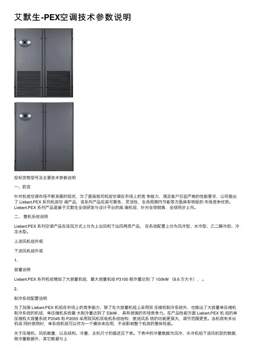
⼆、整机系统说明Liebert.PEX 系列空调产品在送风⽅式上分为上出风和下出风两类产品,在系统配置上分为风冷型、⽔冷型、⼄⼆醇冷却、冷冻⽔型。
上送风机组外观下送风机组外观1、容量说明Liebert.PEX 系列机组增加了⼤容量机组,最⼤容量机组 P3100 制冷量达到了 100kW (8.6 万⼤卡),。
2、制冷系统配置说明为了加强 Liebert.PEX 机组在市场上的竞争能⼒,除了在⼤容量机组上采⽤双压缩机制冷系统外,也推出了⼤容量单压缩机制冷系统的机组,单压缩机系统最⼤制冷量达到了 53kW ,具有很强的市场竞争⼒。
在产品性能⽅⾯ Liebert.PEX 机组的单压缩机⼤容量系统 P2045 和 P2055 采⽤双风机双电机系统结构,使送风系统的功能更强⼤,调节范围更宽。
当机房有多台机组同时使⽤时,单系统机组可以作为⼀个模块来应⽤,不会影响整个机房的整体性能。
关于压缩机、风机数量,以及结构、冷量、主机尺⼨的描述见下表。
下表中的冷量数据为风冷、⽔冷机组下送风机型的数据,除冷量数据外,其它数据与上送风机型相同。
Liebert.PEX 系统描述简表3、风机系统机组送风机外余压可以根据⽤户要求进⾏⾮标调整,对于风帽送风机外余压标准为25Pa,地板下送风标准为75Pa,对于风道送风产品标准送风压⼒为100Pa,风压调整范围为25~200Pa。
超过200Pa 的风压要求请提前向公司申请。
4、电加热器加热量标准为⼀级,在需要增加加热量时可以增加第⼆级加热器。

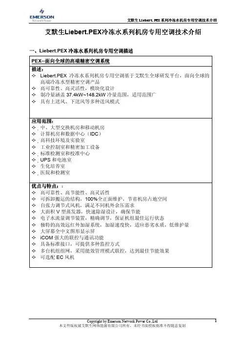
艾默生 Liebert.PEX 系列冷冻水机房专用空调技术介绍 系列冷冻水机房专用空调技术介绍 冷冻水机房专用空调艾默生Liebert.PEX冷冻水系列机房专用空调技术介绍 冷冻水系列机房专用空调技术介绍 艾默生 冷冻水系列机房专用空调技术冷冻水系列机房专用空调描述 系列机房专用空调 一、Liebert.PEX 冷冻水系列机房专用空调描述 PEX─面向全球的高端精密空调系统 面向全球的高端精密空调系统 面向全球的高端 描述: 描述: Liebert.PEX 冷冻水系列机房专用空调基于艾默生全球研发平台,面向全球的 高端冷冻水型精密空调产品 高可靠性、高灵活性,模块化设计 制冷量涵盖 37.4kW~148.2kW 冷量范围,适用范围广 具有上送风、下送风等多种送风模式应用范围: 应用范围: 中、大型交换机房和移动机房 计算机房和数据中心(IDC) 高科技环境及实验室 工业控制室和精密加工设备 标准检测室和校准中心 UPS 和电池室 生化培养室 医院和检测室 优点与特点: 优点与特点:: 特点 高可靠性、高节能性、高灵活性 可拆卸搬运的结构,100%全正面维护,节省机房占地空间 自张力调节式风机,满足不同机外余压需求 大面积 V 型蒸发器,快速除湿设计,确保节能 电子水流量调节装置,精确调节,保证机组最佳运行状态 独特的高效远红外加湿系统,加湿速度快,适应恶劣水质,低维护量 大屏幕全中文图形显示屏 iCOM 强大的联控与通讯功能 具备标准接口,可提供多种监控方式 多台机组组网,采用能效管理模式联控,达到最佳节能效果 可选配 EC 风机Copyright by Emerson Network Power Co.,Ltd 本文件版权属艾默生网络能源有限公司所有,未经书面授权批准不得随意复制1艾默生 Liebert.PEX 系列冷冻水机房专用空调技术介绍 系列冷冻水机房专用空调技术介绍 冷冻水机房专用空调冷冻水系列数据 二、PEX 冷冻水系列数据下送风机组参数 24℃DB,17.1℃ 24℃DB,17.1℃WB, 50%RH总冷量 进水温 7℃ 出水温 12℃ 显冷量 流量 压降 风量 风机数量 电加热 加湿量 满负荷电流 FLA 接管外径¢ 长 机组尺寸 宽 高 重量 kW kW m /h kPa m /h 台 kW kg/h A mm mm mm mm kg3 3P1030F37.4 30.6 6.4 125 8280 1 6 4.5 13.1 32 853 874 1970 260P1040F40.3 32.3 6.9 79 8280 1 6 4.5 13.1 32 853 874 1970 270P1050F47.1 36.0 8.1 105 8280 1 6 4.5 13.1 32 853 874 1970 275P2050F63.1 50.8 10.9 83 11610 2 9 10 23.5 42 1704 874 1970 480P2070F80.2 64.2 13.8 129 16740 2 9 10 23.5 42 1704 874 1970 480P2090F89.0 71.2 15.3 85 16740 2 9 10 23.5 42 1704 874 1970 480P2100F100.6 75.3 17.3 80 16740 2 9 10 23.5 42 1704 874 1970 505P3110F121.8 100.1 21.0 135 25020 3 12 10 28.2 54 2553 874 1970 730P3140F131.1 106.3 22.4 99 25020 3 12 10 28.2 54 2553 874 1970 760P3150F148.2 115.2 25.6 105 25920 3 12 10 28.2 54 2553 874 1970 765Copyright by Emerson Network Power Co.,Ltd 本文件版权属艾默生网络能源有限公司所有,未经书面授权批准不得随意复制2艾默生 Liebert.PEX 系列冷冻水机房专用空调技术介绍 系列冷冻水机房专用空调技术介绍 冷冻水机房专用空调上送风机组参数 24℃DB,17.1℃ 24℃DB,17.1℃WB, 50%RH总冷量 进水温 7℃, 出水温 12℃ 显冷量 流量 压降 风量 风机数量 电加热 加湿量 满负荷电流 FLA 接管外径¢ 长 机组尺寸 宽 高 重量 kW kW m /h kPa m /h 台 kW kg/h A mm mm mm mm kg3 3P1030U36.8 30.2 6.4 121 8100 1 6 4.5 13.1 32 853 874 1970 260P1040U41.4 32.8 7.2 84 8280 1 6 4.5 13.1 32 853 874 1970 270N/An/aP2050U61.1 49.2 10.5 78 11070 2 9 10 23.5 42 1704 874 1970 480P2070U78.1 62.2 13.4 124 16020 2 9 10 23.5 42 1704 874 1970 480P2090U88.1 70.1 15.1 86 16740 2 9 10 24 42 1704 874 1970 480N/An/aP3110U118.2 94.0 20.3 127 23940 3 12 10 28.2 54 2553 874 1970 730P3140U131.9 101.9 22.7 103 23940 3 12 10 28.2 54 2553 874 1970 760N/A注:以上数据基于室内干球温度 24℃,湿球温度 17.1℃, (相对湿度 50%RH) ,进水温度 7℃,出水温度 12℃工况下测定。


内部资料注意保密协议调试手册(Atlas空调)中兴通讯股份有限公司版权所有,保留一切权利。
版权所有,侵权必究。
Copyright (C) 1997 by ZTE Co. Ltd..All rights reserved.设备说明Atlas空调(Liebert空调)CEMS系列CEMS90、CEMS100、Liebert(Challenger M+系列)设备接口描述(尽可能提供设备和接口图片,不同型号设备存在差别)CEMS100型控制系统1 - 温度2 - 相对湿度3 - 机组编号4 - 时间与日期5 - 温度曲线图6 - 相对湿度曲线图7 - 动画符号指示系统工作状态8 - AOM手动/关机/自动动态符号 9 - 电池状态符号10 - 控制键CEMS100型空调Liebert Challenger M+系列空调(如何判断有无接口板、接口板外观描述)CEMS90型的接口位于空调监控模块的面板。
将空调前面的机板移开,可见到一个2*5的十芯接口插座(Remot I/O Port)。
CEMS100型的接口位于空调监控模块的面板反面。
将空调前面的机板移开,从监控板反面的底部可见到一个2*5的十芯接口插座。
如下图:(右上角为1,左上角为10)(接口类型、定义)RS232电平;1-接收、3-发送、10-地(波特率、数据位、校验位、停止位)波特率1200、数据位8位、无校验、起始/停止位1位(操作步骤、拨码设置等)注意空调地址设置:CEMS90型通过转动(UNIT No. SET)上的旋钮,可改变空调的地址。
CEMS100型可通过面板设置各种参数。
面板上有五个按键:↑键、↓键、ENTER确认键、ESC退出键、开关机键。
通讯接口的设置:选择主菜单→系统菜单→通讯,修改波特率-1200,通讯协议-系统;选择主菜单→系统菜单→系统设定,机组编号-XX,可改变空调的地址。
(特殊说明)空调地址为1.调试方法Atlas pcudebug.exe空调地址为1:发送:f0 05 03 01 1d 16接收:f0 06 1a 40 02 34 04 00 ff f7 fe 52 11 08 00 00 81 8b e1 14 82 12 03 fe00 05 01 34 b9空调地址为2:发送:f1 05 03 01 1d 17接收:f1 06 1a 40 02 34 04 00 ff f7 fe 52 11 08 00 00 81 8b e1 14 82 12 03 fe00 05 01 34 ba(通讯是否存在时限要求、是否存在控制条件等)通道表(包括物理通道和逻辑通道)---AI通道信息---AI通道16(双字节64) = 回风温度AI通道17(双字节65) = 回风湿度AI通道18(双字节503) = 温度设置点AI通道19(双字节504) = 湿度设置点AI通道20(双字节106) = 制冷系统运行时间AI通道21(双字节104) = 加湿系统运行时间AI通道22(双字节111) = 风机运行时间---DI通道---DI通道16(双字节3000) = 监控模块故障告警DI通道17(双字节193) = 开关机状态DI通道18(双字节198) = 报警蜂鸣器状态DI通道19(双字节245) = 高温告警DI通道20(双字节246) = 低温告警DI通道21(双字节230) = 传感器故障DI通道22(双字节247) = 高湿告警DI通道23(双字节248) = 低湿告警DI通道24(双字节239) = 无气流(气流丢失故障)DI通道25(双字节236) = 地湿(漏水故障)DI通道26(双字节334) = 压缩机1#压力过高DI通道27(双字节335) = 压缩机2#压力过高DI通道28(双字节195) = 制冷器状态DI通道29(双字节194) = 加热器状态DI通道30(双字节196) = 加湿器状态DI通道31(双字节197) = 除湿器状态DI通道32(双字节303) = 制冷器故障DI通道33(双字节208) = 加湿器故障DI通道34(双字节235) = 风系统维护告警(过滤器脏)DI通道35(双字节209) = 水位低(加湿器缺水)DI通道39(双字节182) = 电源告警DI通道40(双字节205) = 允许远程关机(空调遥控使能)DI通道41(双字节364) = 压缩机1#开机DI通道42(双字节365) = 压缩机2#开机DI通道43(双字节394) = 加热器1#开机DI通道44(双字节395) = 加热器2#开机DI通道47(双字节368) = 加湿状态DI通道48(双字节373) = 除湿状态DI通道50(双字节378) = 风机运行状态---DO通道信息---DO通道38(双字节551) = 开机DO通道39(双字节552) = 关机DO通道40(双字节554) = 告警静音关键及特殊数据(特殊接收函数处理)常见故障(被监控设备监控功能是否可靠)。


TRADE SECRET AND CONFIDENTIAL INFORMATION AGREEMENTThis agreeme nt is made on the day of 2001.Betbee n(“A”)Liebert Corporatio n Australia Pty limited ( “ B”)A ack no wledges receipt fromB a copy of the LECS 15 Communi cati on protocol onthe day of 2001, whice is to be used only in the air-conditioner remote monitoring system ofA hereby con firms that it will preserve and mai nta in in con fide nce the in tellectual property rights of the Protocol, and un dertakes not to disadva ntageB Commercially in any way through its possessi on of the Protocol.B agrees to assist A in the implementation of the remote monitoring system.A: B:Liebert Corporati on Australia Pty LtdStamped: Stamped:Sig nature: Sig nature:Date: Date:LECS 15 COMMUNICA TIONS PROTOCOL1.Date FormatThe port receives and transmits at standard RS232 signal levels. For multiple unit operation diodes may need to be included in the transmit data ( of LECS 15 control ) to preve nt data con flict.Serial data is transmitted and received at 1200 baud.8 data1 stop No parityData is received in a strict block format and any data received which does not conform to this format is ignored by the control.The first byte in the transmitted block contains the unit no. which is being addressed.The unit nu mber corresp onds to the unit no. Displayed on the LECS 15 con trol pan el.2.Control FunctionsThis is 5 bytes message sent to the LECS 15 con trol.Byte 1-( Unit Number-1 ) XOR fOh,e,g,foh for unit no. 1Byte 2-Co ntrol Request 11hex ( ascii DCI char )Byte 3-Nnm ber of bytes to follow in this message02h in this casebyte 4-Co ntrol fun cti on No.called reactivate.OOh remote on-also01h remote off02h alarm muteByte 5-Checksum the least sig nifica nt byte of the binary sum of bytes 1 to 4.UNITNO is the unit number polled;TEMP is the control function number.Resp onse from LECS 15 con trol.The con trol will ack no wledge the con trol fun ctio n request with a 4 b yte message.Byte 1-unit number ( FOh- 92h ) ( see ‘ Control Functions ')Byte 2-ACK character (06h)Byte 3-n umber of bytes followi ng (01h)Byte 4-checksum of bytes 1 to 33.Enquiry FunctionsThere is a 5 or more byte message sent to the LECS 15 control.Byte 1-(unit Number T) XOR f0h, e.g.f0h for unit no. 1Byte 2-E nquiry Request 05h (Enq ASCll char)Byte 3-Number of bytes to follow in this message(n+2)Byte 4- Enquiry function no.00h status dump in sta ntan eous temp & humidity01h status dump averaged temp & hum02h ROM data/time dump03h 48 hour data dumpByte 4 + n -data necessary for each enquiry function request n bytes longByte 4 + n + 1 -checksumEnquiry Fun cti on request and resp on se.a)00h status dump with in sta ntan eous temps & humidity01h status dump with averaged temp & humidityn=0 in the message, xo the request is 5 bytes longByte 1-(unit Number -1) XOR f0h, e.g.f0h for unit no. 1Byte 2-E nquiry Request 06h (Ack ASCll char)Byte 3-Number of bytes to follow in this message 29hByte 4-Co ntroller type and ON/OFF statusBit 0 = —> Unit ONBit 1 = —> Alarm Buzzer OnBit 7 = —> Data Chiller Un it —> LECS15 unitBit 2 to 6 —Un defi nedByte 5,6 — (Temperature * 10) in BCD Hl/O byte format.Byte 9 to 11 — Alarm Bytes (see Byte 12 — Temperature and Humidity Setpoi ntTemp = 17 + ((Byte 12) AND f0h)/16 Deg CHum = 42 + ((Byte 12) AND 0fh)*2% rHByte 13 to 16 — Keyboard Data (see ‘ Keyboard Bytes ')Byte 17 to 22 — I/O Port Data (see Byte 23,24 — Cooling System Hours (HI/LP Bytes)Byte 25.26 — Humidity System Hours (HI/LP Bytes)Byte 27,28 — Air System hours (HI/LP Bytes)Byte 29 — Checksum = (SUM(Byte 1 to 28)) and ffh.b) 02h ROM date time dumpn = 0 — > 5 byte messagec) 03h — data Dump from internal RamFor this case 2 bytes follow byte #4. This function retrieves at most 30*2 minute records (1 hour) starting from the record indicate by the 2 bytes following byte 4. This umber is the binary representation of the first two minute data record to be retrieved.Note1 — the first record dumped is the most rece nt.Note2 — if the RAM has been reset by powering up the dip switch (No.9) on, then a record may be <50 ' 2 min records long.Note3 — the maximum nu mber of records if 1440.Note — any record with a zero value for bytes 5 should be igno red, and that record only serves as a place marker the dump while the unit was tur ned off.Alarm CodesAlarm are contained in Bytes 9 to 11 of the Status enquiry reply and Bytes 5 to 7 of each 2 minute record in the Data Dump reply . The ordering of the alarm bytes is the same in both replies. Startingwith the first byte. The interpretation of thealarm bytes follow.Alarm Byte 1 —Bit -+ 0 — > Temp High Alarm Codes ')I/O Port Bytes ')Bit 1 = 0 — >Temp LoBit 0,1 = 00 — >Sen sor Board faultBit 2 = 0 — >Hum HighBit 3 = 0 — >Hum LowBit 4 = 0 — >No Air FlowBit 5 = 0 — >Water Un der FloorAlarm Byte 2 —Bit 1 = 0 — > Compressor 1 High PressureBit 2 = 0 — > Compressor 2 High PressureBit 3 = 0 — >COOL modeBit 4 = 0 — >HEAT modeBit 5 = 0 — >HUMIDIFY modeBit 6 = 0 — >De HUMIDIFY mode Alarm Byte 3 —Bit 0 = =0 - -> System Service requiredBit 1 = =0 --> System Service requiredBit 2 = =0 --> System Service requiredBit 3 = =0 - -> Water level LowBit 4 = =0 --> Spare AlarmBit 5 = =0 --> Spare AlarmBit 6 = =0 --> Spare AlarmBit 7 =0 - -> Mains Power FailureI/O Port BytesThe state of the I/O ports are contained in bytes 17 to 22 of the Status Enquiry reply. The in terpretati on of these Bytes are as follows.I/O Byte 1 —Bit 5 = 1 — > Remote Shutdow n en abledI/O Byte 2 —Bit 3 = 1 — > Compressor 1 onBit 4 = 1 — > Compressor 2 onBit 5 = 1 — > Heater 1 onBit 6 = 1 — > Heater 2 onBit 7 = 1 — > Hot Gas By-Pass onI/O Byte 3 —Bit 4 to 7 — Chilled Water Value Ope ning% ope n = (((I/O Byte 3) AND f0h)/16)/15*100I/O Byte 4 —Bit 0 = 1 — > Flush Value Ope nBit 1 = 1 — > Humidifier OnBit 2 = 1 — > DeHum Fan mode OnBit 4 = 1 — > Fan OnI/O Byte 5 —Bit 0 = 0 — >Secondary Unit Enabled I/O Byte 6 —Not applicableKeyboard BytesThese are contained in bytes 13 to 18. KBD Byte 1 -Bit 2 = 0--> 1 Deg C & 5%rH Differe ntial -> Deg C & 10%rH Differe ntial KBD Byte 2 —Bit 2,3 = 00 — > 5 sec flush time=10 — > 10 sec flush time=01 — > 20 sec flush time。

协议图号05125398-XY 版本V100 第1页共22 页ACM03U1控制器监控通讯协议艾默生网络能源有限公司目次1.物理接口 (3)2.通信方式 (3)3.信息类型及协议的基本格式 (3)3.1信息类型 (3)3.2协议的基本格式 (3)3.3数据格式 (5)3.3.1 基本数据格式 (5)3.3.2 LENGTH数据格式 (5)3.3.3 CHKSUM数据格式 (6)3.3.4 INFO数据格式 (6)4.编码表 (6)5.协议内容 (7)5.1获取模拟量数据(定点数)(42H) (7)5.2获取开关输入状态(43H) (8)5.3遥控开关机(45H) (10)5.4获取系统参数(定点数)(47H) (10)5.5设定系统参数(定点数)(49H) (11)5.6获取监测模块时间(4DH) (12)5.7设定监测模块时间(4EH) (13)5.8获取通信协议版本(4FH) (13)5.9获取设备地址(50H) (14)5.10获取厂家信息(51H) (15)5.11获取机组状态(82H) (15)5.12获取机组运行模式和报警状态(85H) (17)5.13获取模拟量输出(86H) (21)精密空调控制器监控协议本文规定了精密空调控制器与后台监控、之间的通讯协议规范。
本文以电总协议:《监控行标第三部分:智能设备通信协议》为依据,根据精密空调规范而制定,并扩展了相应命令。
1.物理接口串行通信口采用RS485/RS232。
信息传输方式为异步方式,起始位1位,数据位8位,停止位1位,无校验。
数据传输速率为1200、2400、4800、9600和19200bits可以设置。
2.通信方式在局站内的监控系统为分布式结构。
局站监控单元(SU)与设备监控模块(SM)的通信为主从方式,监控单元为上位机,监控模块为下位机。
SU呼叫SM并下发命令,SM 收到命令后返回响应信息。
SU 500ms内接收不到SM响应或接收响应信息错误,则认为本次通信过程失败。
空调技术简介制冷技术的成熟应用性(指在专用空调领域设计、研发、制造情况)艾默生网络能源有限公司力博特品牌机房专用空调是世界上第一台机房专用空调品牌,具备40年的设计、研发、制造经验,40年来,生产、销售量均具世界首位。
LIEBERT(力博特)为艾默生网络能源有限公司精密空调产品及UPS产品的品牌商标。
LIEBERT公司创建于1942年,当时主要生产冷藏设备。
于1964年生产了全世界第一台恒温恒湿精密专用空调,并于当年承接了IBM公司相当于LIEBERT 公司当年全年产量的订单。
力博特空调产品以高精度、低维护、寿命长著称,目前在全国拥有应用15年案例40余个。
2004年6月统计,在中国超过8年应用以上案例1483台机组。
目前艾默生网络能源有限公司力博特品牌空调在国内的占有率达到55%,15年来稳居首位。
制冷技术的先进性其主要技术特点包括:1、机组:长1664×宽877×高1950)。
侧面及背面不需要维护空间,前面只需要600mm维护空间。
室外机体积小(长1820×宽907×高960)。
2、可拆卸后搬运,保证重新组装与整机无差别,适合特殊场地搬运(如利用小电梯或狭小通道)。
3R407C、R410A),如目前选用R22,当考虑换用环保制冷剂时(如2008年全面禁止R22时),可通过简单的技术处理实现。
4、低噪音设计。
5、大表面积的 V 型蒸发器盘管,双系统设计,确保节能。
6功能,机组自动定期大水量冲洗加湿罐,延长加湿罐维护时间,增加寿命。
7矩阵LCD全中文显示屏,图形化显示多种信息,并提供帮助菜单。
8、提供先进的LECS15C微处理控制器,直接提供RS232接口,提供监控协议,无需另配监控卡。
a)压缩机系统应用高能效比的谷轮(Copeland,艾默生子公司,世界上最大的涡漩式压缩机生产厂)公司涡漩式( SCROLL )压缩机。
涡漩压缩机的活动部件的减少使机组的噪声及震动降低很多;压缩机的压缩过程连续、平稳;压缩机的排气过程旋转角度超过540度;在吸气及压缩过程中没有热量交换;在压缩过程中制冷剂气流方向没有改变;减少了气流损失;涡漩式压缩机无需高、低压阀门;减少了阀门损失,防止产生液击;启动电流低。
一、Liebert.PEX系列描述应用范围:中、大型交换机房和移动机房计算机房和数据中心(IDC)高科技环境及实验室工业控制室和精密加工设备标准检测室和校准中心UPS和电池室生化培养室医院和检测室高适应性:多项节能设计多种送风方式,满足不同气流组织需求多种冷却方式,包括风冷、水冷、乙二醇冷却及冷冻水等,有利于适应现场的实际条件适应R22、R407C等不同冷媒多种监控方式风冷冷凝器提供适合不同温度环境(包括低温启动)的配置风冷方式提供超远安装距离和超高落差的方案二、Liebert.PEX系列数据下送风风冷机组技术参数2上送风风冷机组技术参数3三、Liebert.PEX机组的特点●高可靠性、高节能性、全寿命低成本●同等制冷量条件下,占地面积最小。
侧面及背面不需要维护空间,前面只需要600mm维护空间●可拆卸后搬运,保证重新组装与整机无差别,适合特殊场地搬运(如利用小电梯或狭小通道)●艾默生Copeland高效涡旋式压缩机,直接适合环保制冷剂(R407C)。
●自适应风机系统,满足不同机外余压需求●大面积V型蒸发器,快速除湿设计,确保节能●独特的高效远红外加湿系统,加湿速度快,适应恶劣水质,低维护量●全中文图形显示屏●全中文图形LCD显示屏,强大的群控与通讯功能四、Liebert.PEX机组的设计Liebert.PEX风冷系统的室内机由压缩机、蒸发器、加热器、风机、控制器、远红外加湿器、热力膨胀阀、视液镜、干燥过滤器等主要部件组成。
水冷系列还包括高效板式换热器、水流量调节阀。
室内侧制冷系统和水系统中可能涉及维护、更换的器件全部采用易拆卸的Rotalock连接方式,使维护更方便。
✧PEX风冷机组整机性能体现了高可靠性、高灵活性、高节能率、全寿命低成本。
✧PEX可靠性充分体现在:PACC智能控制系统;Copeland涡旋压缩机;自适应风机系统;远红外加湿系统;全调速低噪声冷凝器等✧PEX高灵活性、高节能率充分体现在:PACC智能控制系统;自适应风机系统;远红外加湿系统;全调速低噪声冷凝器;占地面积小;可拆卸搬运,全正面维护;可直接应用环保制冷剂等✧PEX全寿命成本充分体现在:PACC智能控制系统;Copeland涡旋压缩机;自适应风机系统;V型蒸发器;快速除湿系统;远红外加湿系统;全调速低噪声冷凝器等✧采用真正的模块化设计思路。
艾默生CM空调通信协议Liebert 艾默生CM空调通信协议Liebert是一个为了实现空调远程监控和控制而设计的通信协议。
该协议通过网络连接,使用户能够通过电脑、手机等设备对空调进行实时监控和控制。
本文将对艾默生CM空调通信协议Liebert的特点和功能进行详细介绍。
一、艾默生CM空调通信协议Liebert的特点1. 高效可靠:艾默生CM空调通信协议Liebert采用先进的通信技术,确保了通信的高效和可靠性。
无论是在局域网还是广域网环境下,用户都可以快速地接入并进行远程监控和控制。
2. 多样化接入方式:艾默生CM空调通信协议Liebert支持多种接入方式,可以通过以太网、Wi-Fi和GSM等方式实现远程接入。
用户可以根据需要选择最适合自己的接入方式。
3. 实时监控和控制:利用艾默生CM空调通信协议Liebert,用户可以实时监控空调的运行状态,包括温度、湿度、风速等参数。
同时,用户还可以对空调进行远程控制,如调节温度、设置定时等功能。
4. 数据存储和分析:艾默生CM空调通信协议Liebert具有数据存储和分析的功能,可以对历史数据进行存储和分析,提供有效的数据支持和决策依据。
5. 报警功能:艾默生CM空调通信协议Liebert可以实时监测空调的异常情况,并及时发出报警。
用户可以通过手机短信、邮件等方式接收到异常报警信息,以便及时采取相应的措施。
二、艾默生CM空调通信协议Liebert的功能1. 远程监控:用户可以通过电脑、手机等设备,随时随地实时监控空调的工作状态。
通过界面直观地了解空调的各项参数,如温度、湿度、运行时间等。
2. 远程控制:用户可以通过艾默生CM空调通信协议Liebert,远程控制空调的开关、温度设置、风速调节等功能。
无需亲自前往空调所在的位置,即可实现对空调的远程控制。
3. 数据存储和分析:艾默生CM空调通信协议Liebert可以将空调的历史数据进行存储,并提供数据分析功能。
艾默生精密空调iCOM 控制器简易操作手册简易手册1 控制器艾默生PEX系列空调和CRV空调均采用iCOM 控制器,用户界面操作简洁。
多级密码保护,能有效防止非法操作。
控制器具有掉电自恢复功能,以及高/低电压保护。
通过菜单操作可以准确了解各主要部件运行时间。
专家级故障诊断系统,可以自动显示当前故障内容,方便维护人员进行设备维护。
可存储400条历史事件记录。
配置RS485接口,通信协议采用信息产业部标准通信协议。
微处理控制器面板如图1-2所示。
图1-1 微处理控制器面板iCOM控制器iCOM控制器采用菜单式操作,监控、显示并运行精密冷却空调设备,控制环境保持在设定的范围内。
本章主要介绍iCOM 控制器菜单操作,控制特点和参数设置。
1.1 液晶显示屏Liebert.PEX系列空调正面有一个液晶显示屏,可显示机房当前状态,如温度和湿度等;用户还可以从显示屏上查看和修改机器配置。
液晶显示屏采用蓝色背光,超过一定时间(可配置,默认为5min)无任何按键操作时,背光熄灭;下次按键操作时,背光点亮。
1.2 按键指示灯面板按键指示灯面板上设置有上移键、下移键、左移键、右移键、回车键、退出键、开/关键、报警消音键、帮助键以及报警指示灯和工作指示灯,如图5-1所示。
图1-2 控制器按键和指示灯1.报警指示灯有报警产生时,报警指示灯呈红色;报警消除时,报警指示灯熄灭。
2.工作指示灯机组工作时,工作指示灯呈绿色;机组关闭时,工作指示灯呈黄色。
3.开/关键开关机。
系统运行时,按下开关键,系统关闭;系统关闭时,按下开/关键,系统开启。
注意系统上电后机组的运行状态将按照上次掉电时机组的运行状态,例如在掉电时系统若处于工作状态,那么上电之后系统将自动进入运行状态,无须用户手动开启。
4.回车键进入选择的菜单界面,参数修改完毕后,按回车键确认并保存设定值。
进入菜单条或修改参数时,菜单和参数反显。
5.退出键退出本级菜单界面至正常界面或上一级菜单界面。
TRADE SECRET AND CONFIDENTIAL INFORMATION AGREEMENTThis agreement is made on the day of 2001.Betbeen(“A”)Liebert Corporation Australia Pty limited (“B”)A acknowledges receipt fromB a copy of the LECS 15 Communication protocol on the day of 2001, whice is to be used only in the air-conditioner remote monitoring system ofA hereby confirms that it will preserve and maintain in confidence the intellectual property rights of the Protocol, and undertakes not to disadvantageB Commercially in anyway through its possession of the Protocol.B agrees to assist A in the implementation of the remote monitoring system.A: B:Liebert Corporation Australia Pty Ltd Stamped: Stamped:Signature: Signature:Date: Date:LECS 15 COMMUNICA TIONS PROTOCOL1. Date FormatThe port receives and transmits at standard RS232 signal levels. For multiple unit operation diodes may need to be included in the transmit data ( of LECS 15 control ) to prevent data conflict.Serial data is transmitted and received at 1200 baud.8 data1 stopNo parityData is received in a strict block format and any data received which does not conform to this format is ignored by the control.The first byte in the transmitted block contains the unit no. which is being addressed. The unit number corresponds to the unit no. Displayed on the LECS 15 control panel.2. Control FunctionsThis is 5 bytes message sent to the LECS 15 control.Byte 1-( Unit Number-1 ) XOR f0h,e,g,foh for unit no. 1Byte 2-Control Request 11hex ( ascii DCI char )Byte 3-Nnmber of bytes to follow in this message02h in this casebyte 4-Control function No.called reactivate.00h remote on-also01h remote off02h alarm muteByte 5-Checksum the least significant byte of the binary sum of bytes 1 to 4. UNITNO is the unit number polled;TEMP is the control function number.Response from LECS 15 control.The control will acknowledge the control function request with a 4 b yte message. Byte 1-unit number ( F0h-92h ) ( see ‘ Control Functions’)Byte 2-ACK character (06h)Byte 3-number of bytes following (01h)Byte 4-checksum of bytes 1 to 33. Enquiry FunctionsThere is a 5 or more byte message sent to the LECS 15 control.Byte 1-(unit Number – 1) XOR f0h, e.g.f0h for unit no. 1Byte 2-Enquiry Request 05h (Enq ASCll char)Byte 3-Number of bytes to follow in this message(n+2)Byte 4- Enquiry function no.00h status dump instantaneous temp & humidity01h status dump averaged temp & hum02h ROM data/time dump03h 48 hour data dumpByte 4 + n – data necessary for each enquiry function request n bytes longByte 4 + n + 1 – checksumEnquiry Function request and response.a) 00h status dump with instantaneous temps & humidity01h status dump with averaged temp & humidityn=0 in the message, xo the request is 5 bytes longByte 1-(unit Number – 1) XOR f0h, e.g.f0h for unit no. 1Byte 2-Enquiry Request 06h (Ack ASCll char)Byte 3-Number of bytes to follow in this message 29hByte 4-Controller type and ON/OFF statusBit 0 =-> Unit ONBit 1 =-> Alarm Buzzer OnBit 7 =-> Data Chiller Unit -> LECS15 unitBit 2 to 6-UndefinedByte 5,6-(T emperature * 10) in BCD HI/O byte format.Byte 9 to 11-Alarm Bytes (see ‘Alarm Codes’)Byte 12-T emperature and Humidity SetpointT emp = 17 + ((Byte 12) AND f0h)/16 Deg CHum = 42 + ((Byte 12) AND 0fh)*2% rHByte 13 to 16-Keyboard Data (see ‘Keyboard Bytes’)Byte 17 to 22-I/O Port Data (see ‘I/O Port Bytes’)Byte 23,24-Cooling System Hours (HI/LP Bytes)Byte 25.26-Humidity System Hours (HI/LP Bytes)Byte 27,28-Air System hours (HI/LP Bytes)Byte 29-Checksum = (SUM(Byte 1 to 28)) and ffh.b) 02h ROM date time dumpn = 0-> 5 byte messagec) 03h-data Dump from internal RamFor this case 2 bytes follow byte #4. This function retrieves at most 30*2 minute records (1 hour) starting from the record indicate by the 2 bytes following byte 4. This umber is the binary representation of the first two minute data record to be retrieved.Note1-the first record dumped is the most recent.Note2-if the RAM has been reset by powering up the dip switch (No.9) on, then a record may be <50’2 min records long.Note3-the maximum number of records if 1440.Note-any record with a zero value for bytes 5 should be ignored, and that record only serves as a place marker the dump while the unit was turned off.Alarm CodesAlarm are contained in Bytes 9 to 11 of the Status enquiry reply and Bytes 5 to 7 of each 2 minute record in the Data Dump reply. The ordering of the alarm bytes is the same in both replies. Starting with the first byte. The interpretation of the alarm bytes follow.Alarm Byte 1-Bit -+ 0-> T emp HighBit 1 = 0->T emp LoBit 0,1 = 00->Sensor Board faultBit 2 = 0->Hum HighBit 3 = 0->Hum LowBit 4 = 0->No Air FlowBit 5 = 0->Water Under FloorAlarm Byte 2-Bit 1 = 0-> Compressor 1 High PressureBit 2 = 0-> Compressor 2 High PressureBit 3 = 0->COOL modeBit 4 = 0->HEAT modeBit 5 = 0->HUMIDIFY modeBit 6 = 0->De HUMIDIFY modeAlarm Byte 3-Bit 0 = 0-> System Service requiredBit 1 = 0-> System Service requiredBit 2 = 0-> System Service requiredBit 3 = 0-> Water level LowBit 4 = 0-> Spare AlarmBit 5 = 0-> Spare AlarmBit 6 = 0-> Spare AlarmBit 7 = 0-> Mains Power FailureI/O Port BytesThe state of the I/O ports are contained in bytes 17 to 22 of the Status Enquiry reply. The interpretation of these Bytes are as follows.I/O Byte 1-Bit 5 = 1-> Remote Shutdown enabledI/O Byte 2-Bit 3 = 1-> Compressor 1 onBit 4 = 1-> Compressor 2 onBit 5 = 1-> Heater 1 onBit 6 = 1-> Heater 2 onBit 7 = 1-> Hot Gas By-Pass onI/O Byte 3-Bit 4 to 7-Chilled Water Value Opening% open = (((I/O Byte 3) AND f0h)/16)/15*100I/O Byte 4-Bit 0 = 1-> Flush Value OpenBit 1 = 1-> Humidifier OnBit 2 = 1-> DeHum Fan mode OnBit 4 = 1-> Fan OnI/O Byte 5-Bit 0 = 0->Secondary Unit EnabledI/O Byte 6-Not applicableKeyboard BytesThese are contained in bytes 13 to 18.KBD Byte 1-Bit 2 = 0-> 1 Deg C & 5%rH Differential = 1-> Deg C & 10%rH Differential KBD Byte 2-Bit 2,3 = 00-> 5 sec flush time= 10-> 10 sec flush time= 01-> 20 sec flush time。