NPort 5110工业串口联网服务器设置规范(试用)
- 格式:pdf
- 大小:1.24 MB
- 文档页数:11


came.TCP/IP CONNECTION GUIDE MOXA to CATOconnection GUIDEThis manual describes how to install and setup a Moxa Nport 5110TCP/IP Serial Device to enable a Simplekey 4 Door controller to be connected to an Ethernet network.TO BE READ IN CONJUNCTION WITH THENport 5100 Series User’s Manual1Overview (4)The NPORT 5110 Device (4)2Pre-configuration (5)CAME KMS default MOXA network settings: (5)3Information required from installer (5)4Installing the MOXA (6)Power Supply (6)5Connecting the MOXA to CATO (7)CATO (7)CATO connection overview (7)MOXA to CATO connections (8)6Final Commissioning (8)Publication Number: 2.02CAME KMS Publication Date: August 2022This document is to be used in conjunction with the Nport 5100 Series User’s Manual Version 5 April 2019 available at /productThis manual describes how to install and setup a Moxa Nport 5110 TCP/IP Serial Device to enable a Simplekey 4 Door controller to be connected to an Ethernet network.Previous experience with port forwarding and basic networking is assumed.The Moxa Nport 5110 is a hardware product which enables the System Controller to communicate with a local Ethernet Network using it’s RS232 port. The NPORT 5110 has been tested and approved for operation with Simplekey controllers and is available direct from Key Management Systems.In order to connect a Simplekey 4 Controller to the website the following are required:• 1x MOXA Nport 5110 device.• 1x KMS CATO PCB.One System Controller can be controlled to any single MOXA, when using a MOXA only a single system controller can be controlled, connecting two system controllers together is no longer possible.In operation the device places the serial data from the Simplekey Controller into a TCP/IP wrapper before sending it out over the network. Data moving in the other direction i.e. from the network to the NPORT 5110 undergoes the same process in reverseCAME KMS will undertake the initial configuration of the MOXA, these settings rarely need to be changed, please consult CAME KMS Technical support for bespoke setup requirements.• IP Address assignment via DCHP• Port 950• Baudrate = 115200• Data bits = 8• Stop Bits = 2• Parity = none• Flow Control = None• FIFO = enabled• Interface = RS-232The MOXA is password protected, if the device requires unlocking for re-configuration please contact CAME KMS Technical Support.A factory reset of the device is possible which will remove all pre-configuration. Please consult the MOXA Nport series manual for further details.Note: KMS are not responsible for the re-configuration if the MOXA has been factory reset.3KMS will require the following from the installation contractor before a successful connection can be made:• Externally facing IP address – A Static IP address is advantageous in most scenarios as no further changes are required in the event of the IP address changes.• Port number opened and directed at the MOXATwo mounting tags are provided, one each side of the MOXA. It is important to install the MOXA in a location where it can not be easily tampered with, yet no more than 25 metres from the CATO board due to RS232 signal distance limitations. The Ethernet cable can be run up to 100 metres from the router of network switch.yPower is provided by supplied via UK 3 pin plug socket. Alternatively a power jack can be supplied so a 12v connection is taken from the local system PSU.The MOXA connects to the CATO, this is a mezzanine PCB which connects on top of the Simplekey 4 controller. This is pre-fitted by CAME KMS at the factory and should not be removed unless absolutely necessary.Warning! Irreversible damage may occur if the CATO is not fitted correctly on the System Controller.See next page for MOXA to CATO wiring configuration.CAME KMS supply a pre-made DB9 female connection lead, in the event of broken terminations see the pinout table below.6 Final CommissioningOnce all steps have been taken please contact CAME KMS Technical support for connection verification. The installation will require the final steps as per any GPRS connection:• Correct communications between the CAME KMS cloud server and site based TCP/IP device.• Events are being received for each door on the system and events are correct for that door.• Remotely unlock every door on the system to ensure all locks, readers and outputs work as configured.• Make system adjustments including lock release time, door open warning times, trades profiles and any re-labelling of doors.All 3 LED’s shown be active on the front of the MOXA , the Tx/Rx Led will only blink when data is parsed between the MOXA and CATO, this may not be continuous.See the MOXA LED indicator status table below.CAME S.p.A.Came cancelli automatici S.p.A.is certified for Quality and Environment UNI EN ISO 9001UNI EN ISO 14001BS OHSAS 18001CAME KMS/kms。
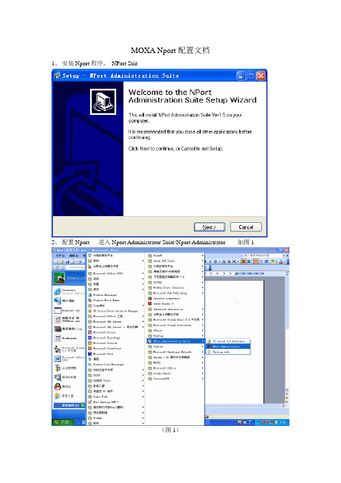
MOXA Nport配置文档1、安装Nport程序。
NPort Suit2、配置Nport 进入Nport Administrator Suite\Nport Administrator 如图1(图1)3、进入后,界面如图2。
在Nport和电脑或者和路由器已经连接好的前提下,点Search。
在“ConFiguration”,可以找到Nport的具体型号。
如图3(图2)(图3)4、双击Nport的记录,如图4。
进入配置界面。
(图4)4、配置界面如图5。
在NetWork分页,选中“Modify”,分配给Nport一个静态的IP地址和子网掩码。
IP地址和子网掩码具体看油库的网段自由分配。
图55、在Serial界面,可以看到这个Nport具体有几个端口。
以及配置修改波特率。
如图6,是2个端口的Nport。
修改波特率的话,选中“Modify”,和具体的一个端口,比如Port1。
点“Settings”,出现界面如图7。
出现图8,修改具体的波特率。
配置图8。
图6图7图86、在Operating Mode分页,如图9。
选中“Modify”和具体的一个端口,点“Settings”出现界面如图10。
Max.Connection配置这个端口同时可以几台电脑通讯。
默认修改为4。
表示最大可以一个主机,三个从机同时通讯。
图10至此,“Configuration”页面配置完毕。
7、现在开始配置“Com mapping”。
在前面已能找到具体Nport型号的前提下,这里自动会出现Nport的相关信息。
这里的Port表示具体的端口号。
图117、双击具体的端口,进入端口的配置界面。
选择“Basic Settings”。
选择使用的端口。
8、选择“Serial Parameters”,配置波特率。
具体配置如图图12 MOXA Nport配置完毕。

NPort 5100A SeriesQuick Installation GuideSecond Edition, June 20101. OverviewNPort 5100A series device servers are compact, palm-sized data communication devices that allow you to control RS-232 (NPort 5110A), RS-422/485 (NPort 5130A), and RS-232/422/485 (NPort 5150A) serialdevices over a TCP/IP-based Ethernet.Note: “-T” indicates an extended temperature model.2. Package ChecklistBefore installing the NPort 5100A series device server, verify that the package contains the following items:1 NPort 5100A serial device server4 stick-on padsDocument & Software CDQuick Installation GuideProduct Warranty StatementOptional AccessoryDK-35A: DIN-Rail Mounting Kit (35 mm)Notify your sales representative if any of the above items are missing or damaged.3. Hardware IntroductionAs shown in the following figures, NPort 5100A series device servers have one male DB9 port for transmitting RS-232 (NPort 5110A),RS-422/485 (NPort 5130A), or RS-232/422/485 (NPort 5150A) serialdata.NOTE: The NPort 5110A, NPort 5130A, and NPort 5150A have thesame form factor.Reset Button—Press and hold the Reset button for 5 seconds to loadfactory defaults: Use a pointed object, such as a straightened paper clip ortoothpick, to depress the reset button. This will cause the Ready LED toblink on and off. The factory defaults will be loaded once the Ready LEDstops blinking (after about 5 seconds). At this point, release the resetbutton.LED Indicators—NPort 5100A’s top panel has three LED indicators,which are described in the following table.LEDNameLEDColorLED FunctionReadyRedSteady on: Power is on and the NPort is booting up.Blinking: Indicates an IP conflict, or DHCP orBOOTP server is not responding properly.GreenSteady on: Power is on and the NPort is functioningnormally.Blinking: The NPort has been located by the NPortAdministrator’s Location function.Off Power is off, or a power error..LinkOrange 10 Mbps Ethernet connection.Green 100 Mbps Ethernet connection.Off Ethernet cable is disconnected.Tx/RxOrange Serial port is receiving data.Green Serial port is transmitting data.OffNo data is being transmitted or received through theserial port.Adjustable pull high/low resistor for RS-422/485 (150 KΩ or 1 KΩ)Jumpers are used to set the pull high/lowresistor value s. The default is 150 KΩ. Shortthe jumpers to set this value to 1 KΩ. Do notuse the 1 KΩ setting with RS-232 mode, sincedoing so will degrade the RS-232 signals andshorten the communication distance.4. Hardware Installation InformationSTEP 1: After removing the NPort 5100A series device server from thebox, connect the NPort 5100A series device server to a network. Use astandard straight-through Ethernet cable to connect to a hub or switch.When setting up or testing the NPort 5100A series device server, youmight find it convenient to connect directly to your computer’s Ethernetport. In this case, use a cross-over Ethernet cable.STEP 2: Connect the NPort 5100A series device server’s serial port to aserial device.STEP 3: Connect the power adaptor.STEP 4: Placement options.In addition to placing the NPort 5100A on a desktop or other horizontalsurface, you may also make use of the DIN-Rail or Wall Mount options,as illustrated below.Wall Mount DIN-RailP/N: 1802051000021— 1— — 2 — — 3 —5. Software Installation InformationTo install NPort Administration Suite, insert the NPort Document & Software CD into your computer’s CD-ROM drive. Once the NPort Installation CD window opens, click on the Installation button, and then follow the instructions on the screen.To view detailed information about NPort Administration Suite, click on the Documents button, and then select “NPort 5100A Series User’s Guide” to open the pdf version of the user’s guide.6. Pin AssignmentsEthernet Port PinoutsPin Number Ethernet1 Tx+2 Tx-3 Rx+6Rx-NPort 5110A—DB9 male (RS-232) port pinoutsPin Number RS-2321 DCD2 RxD3 TxD4 DTR5GND6 DSR7 RTS8 CTS9 --- NPort 5130A—DB9 male (RS-422/485) port pinoutsPin Number RS-422/485 (4W)RS-485 (2W)1 TXD-(A) ---2 TXD+(B)---3 RXD+(B) Data+(B)4 RXD-(A) Data-(A)5 GND GND6 --- ---7 --- ---8 --- ---9 --- ---NPort 5150A—DB9 male (RS-232/422/485) port pinoutsPin Number RS-232 RS-422/485 (4W)RS-485 (2W)1 DCD TXD-(A) ---2 RxD TXD+(B) ---3 TxD RXD+(B)Data+(B)4 DTR RXD-(A) Data-(A)5 GND GND GND6 DSR --- ---7 RTS --- ---8 CTS --- ---9 --- --- ---7. SpecificationsPower RequirementsPower Input 12 to 48 VDCPower Consumption NPort 5110A: 82.5 mA@12V, 47.3 mA@24VNPort 5130A: 89.1 mA@12V, 49.5 mA@24VNPort 5150A: 92.4 mA@12V, 52.8 mA@24VOperating Temperature 0 to 60°C (32 to 140°F), for standard models-40 to 75°C (-40 to 167°F), for -T modelsOperating Humidity 5 to 95% RHDimensions 75.2 × 80 × 22 mm(2.96 × 3.15 × 0.87 in)←with ears52 × 80 × 22 mm(2.05 × 3.15 × 0.89 in)←without earsSerial Line Protection 15 KV ESD for serial portLevel 1 Surge, EN61000-4-5Magnetic Isolation 1.5 KV for EthernetPower Line Protection Level 2 Burst (EFT), EN61000-4-4Level 3 Surge, EN61000-4-5Regulatory Approvals FCC Class A, CE Class A, UL, LVDClick here for online support:/supportThe Americas: +1-714-528-6777 (toll-free: 1-888-669-2872)Europe: +49-89-3 70 03 99-0Asia-Pacific: +886-2-8919-1230China: +86-21-5258-9955 (toll-free: 800-820-5036)2010 Moxa Inc. All rights reserved.Reproduction without permission is prohibited.—4— —5 — — 6 —。

Moxa Nport 5110设置步骤启动Nport Aministrator,单击Search按钮,软件自动搜索网络上的Nport模块搜索到后如下图。
选择COM Mapping按钮,切换到com mapping界面,按下ADD添加按钮,再次添加Nport模块,选择COM口,点击Apply按钮保存并退出软件,此时,串口映射完成,使用串口调试工具检测串口是否可以正常工作ok至此串口映射完成。
文案编辑词条B 添加义项 ?文案,原指放书的桌子,后来指在桌子上写字的人。
现在指的是公司或企业中从事文字工作的职位,就是以文字来表现已经制定的创意策略。
文案它不同于设计师用画面或其他手段的表现手法,它是一个与广告创意先后相继的表现的过程、发展的过程、深化的过程,多存在于广告公司,企业宣传,新闻策划等。
基本信息中文名称文案外文名称Copy目录1发展历程2主要工作3分类构成4基本要求5工作范围6文案写法7实际应用折叠编辑本段发展历程汉字"文案"(wén àn)是指古代官衙中掌管档案、负责起草文书的幕友,亦指官署中的公文、书信等;在现代,文案的称呼主要用在商业领域,其意义与中国古代所说的文案是有区别的。
在中国古代,文案亦作" 文按 "。
公文案卷。
《北堂书钞》卷六八引《汉杂事》:"先是公府掾多不视事,但以文案为务。
"《晋书·桓温传》:"机务不可停废,常行文按宜为限日。
" 唐戴叔伦《答崔载华》诗:"文案日成堆,愁眉拽不开。
"《资治通鉴·晋孝武帝太元十四年》:"诸曹皆得良吏以掌文按。
"《花月痕》第五一回:" 荷生觉得自己是替他掌文案。
"旧时衙门里草拟文牍、掌管档案的幕僚,其地位比一般属吏高。
《老残游记》第四回:"像你老这样抚台央出文案老爷来请进去谈谈,这面子有多大!"夏衍《秋瑾传》序幕:"将这阮财富带回衙门去,要文案给他补一份状子。
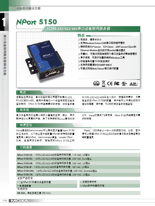
2-19工业自动化完整解决方案 e-mail :china@ 免费技术热线:800-820-5036串口设备联网服务器 > NPort ® 5100系列2故障排除更加容易简介标准TCP/IP 接口和多样的操作模式最具性价比的串口联网解决方案为现有的软件提供Real COM/TTY 驱动5100系列NPort ® 5100串口设备联网服务器是专为串口设备立即联网而设计的。
NPort ® 5100串口设备联网服务器结构紧凑,是连接RS-232/422/485设备到以太网的理想选择。
如读卡器或者付使用串口联网设备将固有的串口设备连接至网络不再是一个空谈。
现在,用户更希望找到一款具有高性价比的产品,不仅能提供多种功能,还需要具备较高的质量。
NPort ®5100系列NPort ® 5100系列支持Real COM/TTY 驱动,让您可以通过COM/TTY 端口继续使用原有的通讯软件。
您无需担心安装和配置问题,NPort ®5100可以让您的串口设备和PC 机与NPort ® 5100支持SNMP V2.0。
通过使用SNMP Manager ,用户可以观察网络上所有NPort ® 5100的状态。
当NPort ®5100发生错误时(用户定义的),它会自动通知SNMP Manager 。
除此之外,该设备还为那些不愿使用SNMP manager 的用户NPort ® 5100串口设备联网服务器提供了TCP Server ,TCP Client ,UDP Server/Client ,Pair Connection 或Ethernet费终端让你可以通过网络,不受地域的限制随时地对串口设备进行存取。
兼容Microsoft 和Linux 的操作系统,并提供5年质保服务,使之成为全球工业领域中最佳的串口设备联网的解决方案。
NPort IA5000系列工業自動化的1和2埠串列設備伺服器特色與優點•通訊端模式:TCP server、TCP client、UDP•用於2線和4線RS-485的專利ADDC®(自動數據流向控制)•串聯乙太網路埠,方便佈線(僅適用於RJ45連接器)•備援直流電源輸入•透過繼電器輸出和電子郵件發出雙重告警•10/100BaseTX(RJ45)或100BaseFX(單模或多模,配備SC連接器)•IP30防護等級外殼認證簡介NPort®IA設備伺服器為工業自動化應用提供簡單可靠的串列轉乙太網路連線。
此設備伺服器可以將任何串列裝置連接至乙太網路,而且為了確保與網路軟體可相容,這些設備伺服器支援多種連接埠操作模式,包括TCP Server、TCP Client和UDP。
NPort®IA設備伺服器的絕佳可靠性使其成為建立網路連線至RS232/422/485串列裝置(例如:PLC、感測器、電表、馬達、驅動器、條碼掃描器和操作人員顯示器)的理想選擇。
所有型號都很輕巧,且有堅固的外殼,可安裝在DIN軌道上。
串聯乙太網路埠可簡化佈線(10/100BaseTX型號)NPort®IA5150和IA5250設備伺服器各有兩個乙太網路埠,可做為乙太網路交換器連接埠。
其中一個連接埠可直接連接至網路或伺服器,另一個可以連接至另一台NPort®設備伺服器或乙太網路裝置。
雙乙太網路埠您毋須將每個裝置單獨連接到一台乙太網路交換機,因此可降低佈線成本。
備援電源輸入NPort®IA5000設備伺服器支援兩個電源輸入,可同時連接兩台直流電源。
如果一個電源發生故障,另一個電源會自動接替。
備援電源輸入有助於確保設備伺服器運作不中斷。
繼電器輸出警告和電子郵件警示當網路斷線、電源故障,或者當DCD或DSR串列訊號發生變化時,內建繼電器輸出可向管理員發出警示。
Web主控台會顯示哪個乙太網路連線或電源輸入發生故障,或者哪個串列訊號發生變化。
第一章:准备工作准备工作我们用一条交叉网线把NPort5110 和PC机的网口连接起来,并把NPort上电。
首先,打开控制面板,网络连接。
在本地连接上点右键,选择属性。
双击进入 Internet协议(TCP/IP),点击“使用下面的IP地址”写入 IP 地址和子网掩码,记住要和NPORT 的IP 地址在同一子网段。
如NPORT 默认IP为192.168.127.254,255.255.255.0;就需要把PC 机的IP 地址设为192.168.127.XXX,255.255.255.0,最后一个数字不同即可。
点击确定。
第二章:网络和串口参数配置搜索 NPort打开NPort Administrator(可以在光盘的对应位置找到这个软件,安装好),点击Search,此时请确认网络防火墙已经关闭。
会搜索到我们的NPort5110,点击stop,停止搜索。
网络参数配置双击右边空白处的NPort 设备,会出现以下界面,点击选择Network 选项卡,点击Modify修改。
可以看到以下界面:我们可以在里面修改NPort的以下参数:IPAddress:IP地址。
Netmask:子网掩码。
Gateway:网关。
IP Configuration:可以配置为静态IP(Static),或者为DHCP(动态IP)。
DNS Server1和2:DNS,域名解析服务器。
串口参数配置点击 Serial选项卡,点击Modify修改,双击端口进去,可以看到以下界面:我们可以在里面修改以下参数:Baud Rate:波特率,NPort5000 系列只能支持标准波特率,如9600,115200bps 等。
Parity:校验。
None:无校验Even:偶校验。
Odd:奇校验。
Space:空。
Mark:标志。
Data Bits:数据位。
Stop Bits:停止位。
Flow Control:流量控制。
None:无流量控制。
XON/XOFF:软件流控。
NPort5110工业串口联网服务器
设置规范(试用)
广州市英沙电子系统有限公司
2016-04-06发布
目录
1引言 (3)
2Nport5110规格 (3)
3设置前准备 (3)
3-1计算机准备 (3)
3-2串口线准备 (3)
3-3网线准备 (3)
4使用的应用软件及测试工具 (4)
5串口服务器设置步骤 (4)
5-1设置计算机本机IP、网关等内容 (4)
5-2设置串口服务器 (6)
5-3通讯是否正常测试 (9)
1引言
工业串口联网服务器被用于将串口设备立即联网。
小巧灵活的尺寸使其非常适用于把含RS-232/422/485接口的高速公路终端设备等接入基于IP地址的网络。
串口服务器让您可以通过计算机软件直接访问网络中的任何串口设备。
Moxa串口服务器专为工业应用而设计。
不同配置组合的串口服务器更能符合不同工业现场的需求。
Nport 系列串口服务器让传统RS-232/422/485设备立即联网,提供您基于IP的串口联网解决方案。
本文以英沙公司用到的NPORT5110串口服务器在LED可变信息标志上的应用为例,详细描述当该串口服务器操作模式为TCP Client Mode时的设置方法。
2Nport5110规格
Nport5110具体资料请查阅以下网址:/Product/NPort_5110.htm。
你也可以在该网站下载Nport5110操作或使用手册,并且可以下载串口服务器配置工具来进行设置。
串口服务器COM端为公头(MALE)。
3设置前准备
3-1计算机准备
准备计算机1台;
3-2串口线准备
准备串口线1条,串口线必须包含第2、3、5脚,且为直通线;用来连接串口服务器与情报板主板(或RS232信号防雷器)RS232接口。
直通线如下表所示:
接串口服务器COM端,使用母头接情报板目标主板(设备)端,使用公头
引脚2,RXD引脚2,TXD
引脚3,TXD引脚3,RXD
引脚5,GND引脚5,GND
请确定连线正确。
3-3网线准备
网线1条,可使用交叉或直通线,如下图所示。
网线用来连接串口服务器与上位机(如计算机)。
4使用的应用软件及测试工具
4-1IE浏览器;
4-2情报板演示工具“情报板测试demo_ver5.0.exe”;
支持XP操作系统。
在实际使用过程中,支持部分WIN10操作系统的计算机。
但客户反馈无法支持部分WIN7、WIN10系统的计算机。
4-3情报板测试工具运行错误解决方案。
当部分计算机无法支持“情报板测试demo_ver5.0.exe”时,可尝试用该解决方案来处理。
5串口服务器设置步骤
Moax Nport5110串口服务器默认的IP地址为192.168.127.254。
5-1设置计算机本机IP、网关等内容
5-1-1打开计算机:控制面板\网络连接。
图5-1-1网络连接界面
5-1-2双击“以太网”,弹出界面如下。
5-1-3点击属性,在弹出的界面上设置如下。
图5-1-3属性设置,右边为设置内容
设置的IP为计算机的IP,此IP可根据实际需要设置,但要与串口服务器IP同一网段。
5-2设置串口服务器
5-2-1用网线把串口服务器与计算机网口连接起来,通电,在IE浏览器上输入IP”192.168.127.254”,弹出界面如下。
5-2-2点击“Network Settings”,可设置串口服务器IP、IP掩膜以及网关。
设置好后点“Submit”提交,然后点“Save/Restart”保存/重启。
备注:如这里更改了IP地址相关内容,则需要对计算机以太网属性中的IP进行重新设置,以保持串口服务器、计算机的IP在同一网段。
5-2-3点击“Serial Settings\Port1”,对串口做如下设置。
设置好后点“Submit”提交,然后点“Save/Restart”保存/重启。
5-2-4点击“Operating Settings\Port1”,对串口服务器操作模式做各种设置。
5-2-4-1串口服务器做客户端使用(TCP Client Mode)
请按照下图进行设置。
5-2-4-2串口服务器做服务器(TCP Server Mode)使用,略。
5-2-4-3串口服务器做实时串口(Real COM Mode)使用,略。
串口服务器设置完成。
5-3通讯是否正常测试
5-3-1打开情报板演示工具“情报板测试demo_ver5.0.exe”。
点菜单“通信控制\通讯设置”。
选择“服务器”,并在服务器端口号上填6001,点建立服务器,会弹出界面“建立服务器成功”,确定后在
情报板测试工具界面右端会显示串口服务器的IP等信息。
5-3-2把情报板测试工具最大化,在右下端收发信息框下,把显示发送与显示接收打勾。
11
NPort5110工业串口联网服务器设置规范(试用)
版本:V16.01发布日期:2016.0406类别:MODULE使用规范
5-3-3双击已登录的客户端,此时会提示串口服务器登录成功;
5-3-4点击演示工具左边图标,如“总状态检测”、“获取亮度”等,会在右下端收发信息框中显示发送的指令和接收的回码;
如回码正确,则表示计算机与情报板通讯建立,串口服务器设置成功。
备注:总状态检测回码字节数为14个,获取亮度回码字节数为13个。
上传播放表后回码一般为0230303130000130f93503,共11个字节。
以上如不对则上传不正确。