吉林大学汽车发动机专业中英文对照成绩单(大四前)
- 格式:pdf
- 大小:118.03 KB
- 文档页数:2
大学中英文成绩单模板范文到了大学,你看到的成绩单是否是中英文版本的呢?下面是给大家带来大学中英文成绩单模板,供大家参阅!北京信息科技大学学生中英文成绩单Beijing Information Science & Technology(BISTU) University Report Card 姓名:Name:学年学期/School Year学号:Student ID:学院:School:专业:Specialty:课程名称/Courses班级:Class:学分/Credits 学制:年Years:Schooling Length:成绩/Scores绩点/Points学年学期/School Year课程名称/Courses学分/Credits成绩/Scores绩点/Points毕业应取得总学分(Total Credits Required for Graduatior)/ 已获得总学分(Total Credits Earned)其中包括(including)必修课(Required)专业选修课(Specialized Elective)公共选修课(Common.Elective)实践课(Practical Course)必修课平均学分绩点(GPA of equired Course)此成绩单仅供出国使用This report is only for going abroad 北京信息科技大学教务处Academic Administration of BISTU 打印日期(PRINT DATE):吉林大学中英文本科成绩单模板Key Comprehensive University Directly Under The Ministry of Education of The People’s Republic of China本科生成绩单Academic Transcript of Undergraduate 姓名:Name:院系:Dept.:学制:Periods of Schooling:学号:专业:入学及毕业时间:吉林大学学生成绩表注释:1. 考试成绩采用优秀、良好、中等、及格、不及格五级记分或百分制记分。
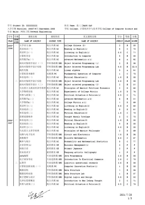
学年学期课程名称课程性质英文课程名称学分等级分数YEAR SEMESTERNAME OF SUBJECT COURSE TYPE NAME OF SUBJECT CREDIT GRADE SCORE 一大学语文(D)校公共课/GC College Chinese(D)2B83英语阅读(一)校公共课/GC Reading in English(1)3C70英语听力(一)校公共课/GC Listening in English(1)0.5C74计算机导论校公共课/GC Introduction to Computer3B80高等数学A(一)校公共课/GC Advanced Mathematics A(1)6A92面向对象程序设计(一)学科基础课/DBC Object Oriented Programming(1)2B86面向对象程序设计实验学科基础课/DBC Object Oriented Programming Lab0.5B82.5线性代数校公共课/GC Linear Algebra3A94计算机基本操作实践课/PC Fundamental Operation of Computer1C75体育选项(一)校公共课/GC Physical Education(1) 1.5B85二面向对象程序设计实验学科基础课/DBC Object Oriented Programming Lab0.5B85面向对象程序设计(二)学科基础课/DBC Object oriented programming(2)2B84马克思主义政治经济学原理校公共课/GC Principles of Marxist Political Economics2D68大学物理实验校公共课/GC Experiments of College Physics 1.5D76形势与政策(一)校公共课/GC Political Situation & Policies(1)0.3C71高等数学A(二)校公共课/GC Advanced Mathematics A(2)5B84大学物理A(一)校公共课/GC College Physics A(1)4D69英语听力(二)校公共课/GC Listening in English(2)0.5D60英语阅读(二)校公共课/GC Reading in English(2)3D64体育选项(二)校公共课/GC Physical Education(2) 1.5C70思想道德修养校公共课/GC Thought Morals Tutelage2C78一体育选项(三)校公共课/GC Physical Education(3) 1.5B80英语阅读(三)校公共课/GC Reading in English(3)3B80英语听力(三)校公共课/GC Listening in English(3)0.5B80马克思主义哲学原理校公共课/GC Principles of Marxist Philosophy2D69电路与电子技术学科基础课/DBC Circuit and Electronics 4.5B86离散数学学科基础课/DBC Discrete Mathematics 5.5C67概率与统计校公共课/GC Probability and Mathematical Statistics3C77企业管理(1)素质教育/CE Business Management(1)2P P 初级日语素质教育/CE Primary Japanese2P P 仿宋美术字素质教育/CE Fangsong Artistic Calligraphy1P P JAVA编程专业选修课/SEC Java Programming 2.5B85电子商务导论专业选修课/SEC Introduction To Electrical Commerce 2.5C75二运筹学专业选修课/SEC Logistics operational research 2.5B85计算机创新实践(一)实践课/PC Computer Innovation Pratice(1)1B85数据结构学科基础课/DBC Data Structure4B86数据结构实验学科基础课/DBC Data Structure Lab1B87数字逻辑与设计学科基础课/DBC Digital Logics and Design 3.5B82毛泽东思想概论校公共课/GC Introduction to Mao Zedong Thought2C71形势与政策(二)校公共课/GC Political Situation & Policies(2)0.3C75学号 Student ID:XXXXXXXXXX姓名 Name:张三/ZHANG SAN入学日期 Enrolled:2005年9月/September,2005学院 College:计算机科学与技术学院/College of Computer Science and2005-20062006-2007专业 Major:网络工程/Network Engineering学年学期课程名称课程性质英文课程名称学分等级分数YEARSEME STERNAME OF SUBJECT COURSE TYPE NAME OF SUBJECTCREDIT GRADE SCORE 学号 Student ID:XXXXXXXXXX姓名 Name:张三/ZHANG SAN入学日期 Enrolled:2005年9月/September,2005学院 College:计算机科学与技术学院/College of Computer Science and专业 Major:网络工程/Network Engineering 英语听力(四)校公共课/GC Listening in English(4)0.5D 67英语阅读(四)校公共课/GC Reading in English(4)3C 72体育选项(四)校公共课/GCPhysical Education(4)1.5A 90法律基础校公共课/GC Fundamentals of Law2D 65一邓小平理论与“三个代表”重要思想概论校公共课/GC Introduction to Deng Xiaoping Theory and the Major Thoughts of “the Three Represents” 2.5C 71计算机组成原理学科基础课/DBCPrinciple of Computer Organization 3C 77计算机组成原理实验学科基础课/DBC Principle of Computer Organization Lab 1C 75汇编语言程序设计学科基础课/DBC Assembly Language Program Design 2B 89汇编语言程序设计实验学科基础课/DBC Assemlby Language Program Design Lab 1A 95数据通信与计算机网络学科基础课/DBC Digital Communication and Computer Network 4B 86.5数据通信与计算机网络实验学科基础课/DBCDigital Communication and Computer Network Lab1C 75数据库系统原理学科基础课/DBC Principle of Database System 3.5B 81计算方法专业选修课/SEC Computational Methods2.5B 80电子商务平台构建实践课/PC E-Commerce Platform Development 0.5C 75计算机创新实践(二)实践课/PC Computer Innovation Pratice(2)1B 85二计算机创新实践(三)实践课/PC Computer Innovation Pratice(3)1A 95网络互连技术专业选修课/SEC Network Connection Techniques 2.5A 95软件工程专业选修课/SEC Software Engineer2.5C 70计算机网络管理实践实践课/PC Commputer Network Management Practice 1C 75网络安全实践实践课/PCNetwork Security Practice0.5C 75TCP/IP协议与网络编程实验专业课/SC TCP/IP Protocols and Network Programming Lab 1A 95网络工程与系统集成技术专业课/SCNetwork Engineering and System Assembly Techniques2A 90网络工程与系统集成技术实验专业课/SCNetwork Engineering and System Assembly Techniques Lab1C 70接口与通信技术实验专业课/SC Interface and Communication Techniques Lab 1B 85TCP/IP协议与网络编程专业课/SC TCP/IP Protocols and Network Programming 2A 94计算机网络管理专业课/SC Computer Network Management 3A 90计算机网络管理实验专业课/SC Computer Network Management Lab 1C 75接口与通信技术专业课/SC Interface and Communication Techniques 3B 81.5形势与政策(三)校公共课/GC Political Situation & Policies(3)0.4C 75网络编程实践实践课/PC Practice for Network Programming 0.5A 95一计算机网络综合实践实践课/PC Computer Network Integrative Practice 1B 85计算机网络安全专业课/SC Computer Network Security 2B 80操作系统学科基础课/DBC Operating System3.5A 93计算机网络安全实验专业课/SC Computer Network Security Lab 1B 85软件开发实践实践课/PC Software Development Practice 1A 95二毕业实践实践课/PC Graduation Practice 3C 75毕业设计实践课/PCGraduation Design12A952007-20082008-2009学年学期课程名称课程性质英文课程名称学分等级分数YEAR SEMESTERNAME OF SUBJECT COURSE TYPE NAME OF SUBJECT CREDIT GRADE SCORE学号 Student ID:XXXXXXXXXX姓名 Name:张三/ZHANG SAN入学日期 Enrolled:2005年9月/September,2005学院 College:计算机科学与技术学院/College of Computer Science and 专业 Major:网络工程/Network Engineering1.成绩 A(优秀)90-100%,B(良好)80-89%,C(中等) 70-79%,D(及格)60-69%,E(不及格)<60%;华侨大学学生成绩单说明:2.课外创新实践、素质教育课及跨学科校选修课程成绩记载为“P(合格)”或“F(不合格)”,该类课程为我校学生课外拓展考查课程,成绩不计入平均绩点及平均分;3.课程性质说明:“校公共课”表示为“GC”,“学科基础课”表示为“DBC”,“实践课”表示为“PC”,“课外创新实践”表示为“EIP”,“素质教育”表示为“CE”,“专业选修课”表示为“SEC”,“专业课”表示为“SC”,“跨学科校选修课”表示为“CEC ”。

汽车发动机外文文献翻译(含:英文原文及中文译文)文献出处:Talom M. AUTOMOTIVE ENGINE[J]. Applied Thermal Engineering, 2013, 2(3):39-45.英文原文AUTOMOTIVE ENGINETalom M1 Engine Classification and Overall MechanicsThe automobile engines can be classified according to: (1) cycles, (2) cooling system, (3) fuel system, (4) ignition method, (5) valve arrangement, (6) cylinder arrangement, (7) engine speed.Engines used in automobiles are the internal combustion heat engines. The burning of gasoline inside the engine produces high pressure in the engine combustion chamber. This high pressure force piston to move, the movement is carried by connecting rods to the engine crankshaft. The crankshaft is thus made to rotate: the rotary motion is carried through the power train to the car wheels so that they rotate and the car moves.The engine requires four basic systems to run (Fig. 2-1). Diesel engines require three of these systems. They are fuel system, ignition system (except diesel), lubricating system andcooling system. However, three other related systems are also necessary. These are the exhaust system, the emission-control system, and the starting system. Each performs a basic job in making the engine run.2 Engine Operating PrinciplesThe term “stroke” is used to describe the movem ent of the piston within the cylinder. The movement of the piston from its uppermost position (TDC, top dead center) to its lowest position (BDC, bottom dead center) is called a stroke. The operating cycle may require either two or four strokes to complete. Most automobile engines operate on the four stroke cycle.In four-stroke engine, four strokes of the piston in the cylinder are required to complete one full operating cycle. Each stroke is named after the action. It performs intake, compression, power, and exhaust in that order.The intake strokeThe intake stroke begins with the piston near the top of its travel. As the piston begins its descent, the exhaust valve closes fully, the intake valve opens and the volume of the combustion chamber begins to increase, creating a vacuum. As the piston descends, an air/fuel mixture is drawn from the carburetor into the cylinder through the intake manifold. The intake stroke endswith the intake valve close just after the piston has begun its upstroke.Compression strokeAs the piston is moved up by the crankshaft from BDC, the intake valve closes. The air/fuel mixture is trapped in the cylinder above the piston. Future piston travel compresses the air/fuel mixture to approximately one-eighth of its original volume (approximately 8:1 compression ratio) when the piston has reached TDC. This completes the compression stroke. Power strokeAs the piston reaches TDC on the compression stroke, an electric spark is produced at the spark plug. The ignition system delivers a high-voltage surge of electricity to the spark plug to produce the spark. The spark ignites, or sets fire to, the air/fuel mixture. It now begins to burn very rapidly, and the cylinder pressure increases to as much as 3-5MPa or even more. This terrific push against the piston forces it downward, and a powerful impulse is transmitted through the connecting rod to the crankpin on the crankshaft. The crankshaft is rotated as the piston is pushed down by the pressure above it.Exhaust strokeAt the end of the power stroke the camshaft opens theexhaust valve, and the exhaust stroke begins. Remaining pressure in the cylinder, and upward movement of the piston, force the exhaust gases out of the cylinder. At the end of the exhaust stroke, the exhaust valve closes and the intake valve opens, repeating the entire cycle of events over and over again.3 Engine Block and Cylinder HeadEngine BlockThe engine block is the basic frame of the engine. All other engine parts either fit inside it or fasten to it. It holds the cylinders, water jackets and oil galleries (Fig. 2-4). The engine block also holds the crankshaft, which fastens to the bottom of the block. The camshaft also fits in the block, except on overhead-cam engines. In most cars, this block is made of gray iron, or an alloy (mixture) of gray iron and other metals, such as nickel or chromium. Engine blocks are castings.Some engine blocks, especially those in smaller cars, are made of cast aluminum. This metal is much lighter than iron. However, iron wears better than aluminum. Therefore, the cylinders in most aluminum engines are lined with iron or steel sleeves. These sleeves are called cylinder sleeves. Some engine blocks are made entirely of aluminum.Cylinder SleevesCylinder sleeves are used in engine blocks to provide a hard wearing material for pistons and piston rings. The block can be made of one kind of iron that is light and easy to cast while the sleeves uses another that is better able to stand up wear and tear.There are two main types of sleeves: dry and wet (Fig. 2-5).Dry sleeve Wet sleeveCylinder HeadThe cylinder head fastens to the top of the block, just as a roof fits over a house. The underside forms the combustion chamber with the top of the piston. In-line engine of light vehicles have just one cylinder head for all cylinders; larger in-line engines can have two or more. Just as with engine blocks, cylinder heads can be made of cast iron or aluminum alloy. The cylinder head carries the valves, valve springs and the rockers on the rocker shaft, this part of valve gear being worked by the pushrods. Sometimes the camshaft is fitted directly into the cylinder head and operates on the valves without rockers. This is called an overhead camshaft arrangement.GasketThe cylinder head is attached to the block with high-tensile steel studs. The joint between the block and the head must begas-tight so that none of the burning mixture can escape. This is achieved by using cylinder head gasket. Gaskets are also used to seal joins between the other parts, such as between the oil pan, manifolds, or water pump and the blocks.Oil PanThe oil pan is usually formed of pressed steel. The oil pan and the lower part of cylinder block together are called the crankcase; they enclose, or encase, the crankshaft. The oil pump in the lubricating system draws oil from the oil pan and sends it to all working parts in the engine. The oil drains off and run down into the pan. Thus, there is a constant circulation of oil between the pan and the working parts of the engine.4 Piston Assembly, piston rings, The piston pin ,Connecting Rods, Crankshafts And FlywheelPistonPiston rings and the piston pin are together called the piston assembly.The piston is an important part of a four-stroke cycle engine. Most pistons are made from cast aluminum. The piston, through the connecting rod, transfers to the crankshaft the force created by the burning fuel mixture. This force turns the crankshaft.To withstand the heat of the combustion chamber, the piston must be strong. It also must be light, since it travels at high speeds as it moves up and down inside the cylinder. The piston is hollow. It is thick at the top where it takes the brunt of the heat and the expansion force. It is thin at the bottom, where there is less heat. The top part of the piston is the head, or crown. The thin part is the skirt. Most pistons have three ring grooves at the top. The sections between the ring grooves are called ring lands.piston ringsPiston rings fit into ring grooves near the top of the piston. In simplest terms, piston rings are thin, circular pieces of metal that fit into grooves in the tops of the pistons. In modern engines, each piston has three rings. (Piston in older engines sometimes had four rings, or even five.) The inside surface of the ring fits in the groove on the piston. The ring's outside surface presses against the cylinder walls. Rings provide the needed seal between the piston and the cylinder walls. That is, only the rings contact the cylinder walls. The top two rings are to keep the gases in the cylinder and are called compression rings. The lower one prevents the oil splashed onto the cylinder bore fro m entering the combustion chamber, and is called an oil ring.The piston pinThe piston pin holds together the piston and the connecting rod. This pin fits into th e piston pin holes and into a hole in the top end of the connecting rod. The top end of t he rod is much smaller than the end that fits on the crankshaft. This small end fits inside the bottom of the piston. The piston pin fits through one side of the piston, through the small end of the rod, and then through the other side of the piston. It holds the rod firmly in place in the center of the piston. Pins are made of high-strength steel and have a hollow center. Many pins are chrome-plated to help them wear better. A piston pin fits into a round hole in the piston. The piston pin joins the piston to the connecting rod. The thick part of the piston that holds the piston pin is the pin boss. Connecting RodsThe connecting rod little end is connected to the piston pin.A bush made from a soft metal, such as bronze, is used for this joint. The lower end of the connecting rod f its the crankshaft journal. This is called the big end. For this big-end bearing, steel-backed lead or tin shell bearings are used. These are the same as those used for the main bearings. The split of the big end is sometimes at an angle, so that it is small enough t o be withdrawn through the cylinder bore. The connecting rod ismade from forged alloy steel.CrankshaftsThe crankshaft is regarded as the “backbone” of the engine (Fig. 2-7). The crankshaft, in conjunction with the connecting rod, converts the reciprocating motion of the piston to the rotary motion needed to drive the vehicle. It is usually made from car-bon steel which is alloyed with a small proportion of nickel. The main bearing journals fit into the cylinder block and the big end journals align with the connecting rods. At the rear end of the crankshaft is attached the flywheel, and at the front end are the driving wheels for the timing gears, fan, cooling water and alternator. The throw of the crankshaft, . the distance between the main journal and the big end centers, controls the length of the stroke. The stroke is double the throw, and the stroke length is the distance that the piston travels from TDC to BDC and vice versa.中文译文汽车发动机Talom M1发动机分类和一般力学(1)循环,(2)冷却系统,(3)燃料系统,(4)点火方法,(5)阀门布置,(6)气缸布置,(7)发动机速度。
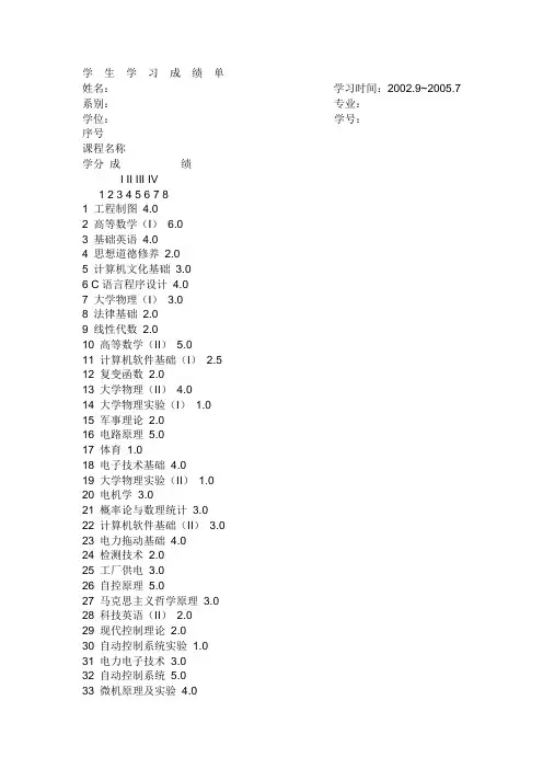
学生学习成绩单姓名:学习时间:2002.9~2005.7 系别:专业:学位:学号:序号课程名称学分成绩I II III IV1 2 3 4 5 6 7 81 工程制图4.02 高等数学(I)6.03 基础英语4.04 思想道德修养2.05 计算机文化基础3.06 C语言程序设计4.07 大学物理(I)3.08 法律基础2.09 线性代数2.010 高等数学(II)5.011 计算机软件基础(I)2.512 复变函数2.013 大学物理(II)4.014 大学物理实验(I)1.015 军事理论2.016 电路原理5.017 体育1.018 电子技术基础4.019 大学物理实验(II)1.020 电机学3.021 概率论与数理统计3.022 计算机软件基础(II)3.023 电力拖动基础4.024 检测技术2.025 工厂供电3.026 自控原理5.027 马克思主义哲学原理3.028 科技英语(II)2.029 现代控制理论2.030 自动控制系统实验1.031 电力电子技术3.032 自动控制系统5.033 微机原理及实验4.0学生学习成绩单姓名:学习时间:2002.9~2005.7 系别:专业:学位:学号:序号课程名称学分成绩I II III IV1 2 3 4 5 6 7 81 工程制图4.02 高等数学(I)6.03 基础英语4.04 思想道德修养2.05 计算机文化基础3.06 C语言程序设计4.07 大学物理(I)3.08 法律基础2.09 线性代数2.010 高等数学(II)5.011 计算机软件基础(I)2.512 复变函数2.013 大学物理(II)4.014 大学物理实验(I)1.015 军事理论2.016 电路原理5.017 体育1.018 电子技术基础4.019 大学物理实验(II)1.020 电机学3.021 概率论与数理统计3.022 计算机软件基础(II)3.023 电力拖动基础4.024 检测技术2.025 工厂供电3.026 自控原理5.027 马克思主义哲学原理3.028 科技英语(II)2.029 现代控制理论2.030 自动控制系统实验1.031 电力电子技术3.032 自动控制系统5.0STUDENT ACADEMIC RECORD (TRANSTATION)NAME: PERIOD: 2002.9~2005.7 DEPARTMENT: SPECITALITY: DEGREE: STUDENT No.:No.COURSE TITLECREDIT RECORDI II III IV1 2 3 4 5 6 7 81 Graphing of Engineering 4.02 Advanced Mathematics(I)6.03 College English 4.04 Thought & Moral Training 2.05 Fundamentals of Computer Science 3.06 C Language 4.07 College Physics(I)3.08 Fundamentals of Law 2.09 Linear Algebra 2.010 Advanced Mathematics(II)5.011 Fundamentals of Computer Software(I)2.512 Functions of Complex Variables 2.013 College Physics(II)4.014 Experiment of College Physics(I)1.015 Military Theory 2.016 Theory of Circuit 5.017 Physical Education 1.018 Basic Electronic Technology 4.019 Electrical Motor 3.019 Experiment of College Physic(II)1.021 Probability & Mathematical Statistics 3.022 Fundamentals of Computer Software(II)3.023 Electrical Machinery & Towage 4.024 Automatic Measurement Technique 2.025 Factory Electricity Supply 3.026 Automatic Control Theory 5.027 Principle of Marxim Philosophy 3.028 Specialty English(II)2.029 Contemporary Control Theory 2.030 Experiment of Automatic Control System 1.031 Power Electronics 3.032 Automatic Control System 5.033 Principle of Single Chip Computer 4.090-100 4.0 A85-89 3.7 A-82-84 3.3 B+78-81 3.0 B75-77 2.7 B-72-74 2.3 C+68-71 2.0 C64-67 1.5 C-60-63 1.0 DCERTIFICATE FOR GRADUATION********** UNIVERSITYCertificate No: 0000000000000This is to certify that LEI FENG, male, born on June 10, 198*, majoring in Mechanical Design, Manufacturing & Automation of this university from September 2001 to June 2005, has successfully fulfilled all curriculums of the four-year undergraduate program of study, and passed the examinations. Hereby he is allowed to graduate.President: DONG CUN RUI************ UniversityJune 30,2005CERTIFICATE FOR THE BACHELOR'S DEGREECertificate No: 0000000000000 This is to certify that LEI FENG, male, born in June 198*, majoring in Mechanical Design, Manufacturing & Automation in the Department of Mechanical Engineering of this university from September 2001 to June 2005, has successfully fulfilled all curriculums of the four-year undergraduate program of study, and has graduated.Upon the examination and verification in conformity with the Regulations of Academic Degrees of the People's Republic of China, he is thereby granted the Degree of Bachelor of Engineering.President of ***** University: DONG CUN RUI Chairman of the Degree Senate: DONG CUN RUIJune 30,2005******大学本科学生学籍成绩表中华人民共和国湖北武汉姓名: 雷锋系部: 机械工程学院专业: 机械设计制造及其自动化学制: 4 年入学日期:2001.9 学号:0000000000制表日期:2007/06/13序号课程学分第一学年第二学年第三学年第四学年第一学期第二学期第三学期第四学期第五学期第六学期第七学期第八学期1 体育4.5 73 75 75 772 工程图学6 85 883 思想道德修养2 814 军训5 845 计算机基础6 90 866 高等数学10 86 907 大学英语16 82 85 87 888 金工实习4 889 毛泽东思想概论1.5 8210 政治经济学2 7711 大学物理7 81 7812 理论力学4 8313 法律基础1.5 8114 电路理论3 8515 线性代数2 9116 概率论与数理统计3 8017 物理实验3.5 88 8318 机械原理3.5 9419 材料力学4.5 8420 工程图学课程设计2 9221 模拟电子技术3.5 8722 哲学2.5 7823 复变函数与积分变换2.5 8724 控制工程基础3 8625 工程材料学3 8926 互换性及技术测量2.5 8227 质量控制技术3 8128 机械设计课程设计3 9129 机械设计4 9230 数字电子技术3.5 8531 邓小平理论概论3 8232 机电传动与控制4 9233 微机原理3 9034 液压与气压传动3.5 8635 测试技术3 8336 计算机软件基础3 8137 专业英语2 8738 机械制造基础4.5 9239 微机接口及应用2.5 8340 数控技术2.5 8841 计算机控制系统3.5 9042 机电一体化系统设计3 8743 CAD/CAM技术2.5 9544 工业机器人2.5 8445 特种加工2 8546 虚拟设计2 9047 液压与气动课程设计2 8748 专业课课程设计3 8849 综合实验1 9050 毕业设计(论文)13 8551 毕业实习4 9052 数控实训2 83UNDERGRADUATE ACADEMIC RECORD OF ********* UNIVERSITY WUHAN, HUBEI, THE PEOPLE' S REPUBLIC OF CHINAName: Lei Feng STUDENT' S NUMBER: 000000000Department: Mechanical Engineering Major: Mechanical Design, Manufacturing & AutomationLength of schooling: 4 years Date of Entrance: September 2001Date of Tabling: 06/13/2007NO. Course Credit 1st AcademicYear 2nd Academic Year 3rd Academic Year 4th Academic Year1st Term 2nd Term 1st Term 2nd Term 1st Term 2nd Term 1st Term 2nd Term1 Physical Education 4.5 73 75 75 772 Engineering Graphics 6 85 883 Cultivation of Ethic Thought 2 814 Military Training5 845 Basis of Computer Engineering6 90 866 Advanced Mathematics 10 86 907 College English 16 82 85 87 888 Metalworking Practice 4 889 Introduction to Mao Zedong Thought 1.5 8210 Political Economics 2 7711 College Physics 7 81 7812 Theoretical Mechanics 4 8313 Fundamentals of Law 1.5 8114 Theory of Circuitry 3 8515 Linear Algebra 2 9116 Probability and Mathematical Statistics 3 8017 Experiment of College Physics 3.5 88 8318 Principle of Mechanics 3.5 9419 Material Mechanics 4.5 8420 Course Design of Engineering Graphics 2 9221 Analogue Electronic Technique 3.5 8722 Philosophy 2.5 7823 Complex Function & Integral Transformation 2.5 8724 Basis of Control Engineering 3 8625 Engineering Materials 3 8926 Interchangeability & Technica 2.5 8227 Quality Control Technique 3 8128 Course Design of Mechanical Design 3 9129 Mechanical Designing 4 9230 Digital Electronic Technique 3.5 8531 Introduction to Deng Xiao-ping theory 3 8232 Electromechanical Drive & Control 4 9233 Principle of Micro-computer 3 9034 Hydraulic & Pneumatic Transmission 3.5 8635 Testing Technology 3 8336 Computer Software 3 8137 Specialty English 2 8738 Machine Building 4.5 9239 Microcomputer Interface and Application 2.5 8340 Digit Control Technique 2.5 8841 Computer Control System 3.5 9042 Opto-electronic-mechanical System Design 3 8743 CAD/CAM Technology 2.5 9544 Industrial Robot 2.5 8445 Specialty Manufacturing 2 8546 Virtual Design 2 9047 Hydraulic and Air Pressure Driven Project Design 2 8748 Professional Course Project 3 8849 Comprehensive Experiment 1 9050 Graduation Project(Thesis) 13 8551 Graduation Practice 4 9052 Digit Control Training 2 83。
本科生毕业设计(论文)翻译资料中文题目:配合新一代液力变矩器的柴油动力线的一些特性英文题目:some properties of a diesel driveline with hydrodynamic torque converters of thelastest generation学生姓名:学号:班级:专业:机械工程及自动化指导教师:吉林大学机械科学与工程学院Some properties of a diesel drive line withhydrodynamic torque converters of the latestgenerationAbstractDynamic properties of a drive line with a controlled Diesel engine, hydrodynamic transmission mechanism, additional gearing and a loading-working machine producing common monoharmonic loading are investigated. Solution of the dynamic problem is based on phenomenological experimental data: drivingtorque-speed characteristic in the part of the prime mover and so-called external static characteristic in the hydrotransmission part. The non-linear task is solved by a modified harmonic balance method that was described in preceding publications by the author.Keywords: Machine drive line; Controlled Diesel drive; Hydrodynamic torque converter; Working machine; Periodic loading; Stationary dynamic stateNomenclature and abbreviationsa, b --- ------Coulomb and viscous non-dimensional friction lossesA i,B i --- ----coefficients in mathematical expression of torque-speed characteristic i, i m ----------kinematic transmission, supplementary gearing transmission ratio -------mean reduced moment of inertia in driving and loading partI, I, k K ---------tangent slopes of λ(i) and K(i) curves respectivelykλK -------------moment transmissionM ------------Diesel-engine momentM D(ω, z) ----controlled torque-speed driving characteristicM Dmax(ω), M Dmin(ω) ---torque-speed characteristic for maximal and minimal fuel supplyM1, (), M2, () ---pump loading moment and turbine driving momentM T1, M T2 ----friction loss moment in driving and loading partM z, M za ----mean value and amplitude of loading moment-------------hydrodynamic converter characteristic radius吉林大学本科毕业论文外文翻译t -------------timeT, T D------------Watt regulator and Diesel-engine time constantu, z ---------gas lever and regulator displacementw -----------common dynamic variableε -----------regulator structural parameterζ -----------regulator damping ratioλ -----------coefficient of rotation momentν -----------loading angular velocity, π-------index denoting mean value and periodical component---------hydraulic medium density----------rotation angleω1, (), ω2 ---pump and turbine angular velocityDM ------Diesel-engineG, G D ---additional and Watt-regulator gearingHdPT ---hydrodynamic power transmissionIJ --------InjectorLM ------loading mechanism (working machine)P, R, T---pump, reactor, turbineArticle OutlineNomenclature1. Introduction2. Mathematical model of the system3. Stationary dynamic solution at monoharmonic loading4. Results evaluation and concluding remarks1. IntroductionDynamic properties of a drive line (actuating unit) consisting of a controlled Diesel engine (DM), hydrodynamic power transmission system (HdPT), additional gearing (G) and a loading mechanism (LM) or working machine are investigated. The working machine loads the prime mover and the transmissions with a prescribed moment. A simple idealised schematic layout of the complete system is given in Fig.1. The considered Diesel engine is a standard production: ZETOR 8002.1 controlled by a mechanical (Watt’s) or electronic regulator R D governing fuel injector IJ. In the place of the hydrodynamic power transmission there are gradually applied hydrodynamic torque converters of the latest generation that have been projected吉林大学机械科学与工程学院and tested in WUSAM (Research and Projecting Institute of Machines and Mechanisms), j.s.c. Zvolen, Slovakia. These converters represent a three component assembly composed of a rotational pump (P), turbine (T) and a reactor (R) that may revolve in one direction as a free wheel. Advantage of these converters is the fact that their external dimensions and the dimensions of their individual components are identical and they may be mutually changed and arbitrarily combined in order to reach demanded properties. They differ only by internal configuration and blade geometry. According to [1] up to now more than 70 various types have been experimentally tested and from them the ones have been chosen that optimally fulfilled required properties. The mechanical system under consideration represents a sophisticated energy transfer chain from a source––prime mover to working mechanism. Because every real drive is of finite power, any periodic loading always evokes vibrations of all the dynamic variables even though we suppose all the connecting shafts and gearings rigid and backlash free. The influence of dynamic loading on the prime mover may be just controlled by a suitable choice of the torque converter.Fig. 1. Schematic layout of the Diesel drive line.In the paper influence of constant and periodic loading on time course of all the dynamic variables of the system (and particularly on the variables of the prime mover) is investigated at application of some selected types of hydrodynamic torque converters of the latest generation. For fulfilling this task it is necessary to create a suitable mathematical model of the whole combined system and then find its stationary solution corresponding to a required loading.2. Mathematical model of the system吉林大学本科毕业论文外文翻译At the beginning it is necessary to emphasize that mathematical modelling of the drive line in question is based, in our approach, on knowledge of the published phenomenological data: stationary torque-speed characteristic of the prime mover and so-called external static characteristic of the applied hydrodynamic torque converter. It is a much simpler process than modelling based on thermodynamic equations of burning fuel mixture in the Diesel engine and on hydrodynamic equations of real streaming working medium in very complicated cavities of the torque converter. The characteristics are usually given by manufacturer of the individual system components. This is different and simpler approach to solution of the problem than one may find e.g. at Ishihara [2], Hrovat and Tobler [3], Kesy and Kesy [4], Laptev [5] and some others. The derived dimensional and non-dimensional mathematical models of the mechanical system are introduced in [6]. Thenon-dimensional, reduced, so-called single-shaft model (in the driving and loading part), was derived in the form of combined system of the following differential and algebraic equations:(1)(2)(3)(4)M2=KM1, (5)λ=λ(i), (6)K=K(i), (7)(8)吉林大学机械科学与工程学院(9) where the meaning of the individual symbols is explained in nomenclature. In the non-dimensional model all the dynamic variables and parameters are expressed by means of properly chosen relative standard quantities so that the model of the system might be the most simple. Transformation of the original equations system to the non-dimensional form Figs. (1), (2), (3), (4), (5), (6), (7), (8) and (9) is described in detail in [6]. As for this cited paper, it is necessary to say that the relative standard value of loading angular frequency has been settled according to the relation, where in denominator is relative standard value of time. For this value,the time constant of the regulator has been just chosen, i.e. , where therelated dimensional dynamic variables are distinguished by upper bars. The introduced mathematical model has nine variables: M, M1, ω1, z, λ, K, i, M2, ω2 and their meaning is explained in nomenclature. The first three equations represent mathematic model of the prime mover where in inertia moment I there is includedinertia moment of the pump and equivalent part of the working medium because driving and pump shafts are connected by a rigid clutch. The right side of Eq. (3) represents the controlled stationary torque-speed characteristic for which it holds: M D(ω1,z)=M Dmax(ω1)-[M Dmax(ω1)-M Dmin(ω1)]z, (10) where M Dmax(ω1), M Dmin(ω1) represent its non-dimensional extreme branches for maximal and minimal fuel supply and z is the non-dimensional regulator deviation.If the experimentally measured dependences M Dmax(ω1), M Dmin(ω1) are expressed by second degree polynomials then the controlled non-dimensional torque-speed characteristic has the form:(11) From the introduced model it is evident that at chosen parameter value u driving speed growth causes regulator displacement to increase and fuel supply to decrease. The idealised controlled torque-speed characteristic for a chosen parameter value u (gas lever displacement) is schematically depicted in Fig. 2. From Eq. (2) it is evident that the structural parameter ε must be chosen in such away that regulator self-oscillations should not occur. Eqs. Figs. (4), (5), (6), (7) and (8), in the sense of considerations in [6], represent the dynamic equations of the torque converter. Eq. (9) represents simplified motion equation of the loading mechanism under assumptiondoes not depend on rotation angle . In thisthat the reduced inertia moment Ireduced inertia moment there is involved inertia moment of the turbine with吉林大学本科毕业论文外文翻译equivalent part of the working medium too. It is obvious that in this inertia moment and in all moments of the loading mechanism there is considered gear ratio i m of the supplementary gearing of the originally non-reduced system. Eqs. Figs. (6) and (7) represent the external static characteristic of the hydrodynamic transmission, i.e. formal dependences of λ and K on the kinematic ratio i and the dependences are given for every converter type in graphical form. The dynamic variables λ and K are defined in non-dimensional form very simply by non-linear relations Figs. (4) and (5). In a general way these non-dimensional variables are defined by means of dimensional values (distinguished by upper bars) as follows:(12) where individual symbol meaning may be found in nomenclature. As we have chosen (according to Fig. 2) for the relative standard value of angular velocity the idle motion angular velocity of the Diesel engine at maximal fuel supply, i.e. at z = 0, then from Figs. (4) and (12) it is evident that the relative standard moment value is(13)It means that if for the applied drive s−1 and all the applied convertertypes have equal characteristic radius m and if we consider mean valuekg m−3 at stationary thermic regime then the relative standard value of themoment is N m for all the considered converter types. The external static characteristics of the applied converters with internal labelling: M350.222,M350.623M, M350.675, M350.72M3M, are (according to the measuring records [7]) successively introduced in Fig. 3(a)–(d). When the torque-speed characteristic is known and the measured dependences Figs. (6) and (7) are at disposal, it is possible to solve the combined system of differential and algebraic equations Figs. (1), (2), (3), (4), (5), (6), (7), (8) and (9). This is a little complicated task because the differential and algebraic equations in the accepted mathematical model arenon-linear. Stationary dynamic state of the system was calculated by a modified harmonic balance method that is fully described in [8].吉林大学机械科学与工程学院Fig. 2. Idealised diagram of the driving torque-speed characteristic.Fig. 3. External static characteristics of the hydrodynamic power transmissions: M350.222,M350.623M, M350.675, M350.72M3M.3. Stationary dynamic solution at monoharmonicloadingIn this section stationary solution of the system Figs. (1), (2), (3), (4), (5), (6), (7), (8) and (9) will be looked for always with the same prime mover and successively considering all the converters types whose external static characteristics are introduced in Fig. 3(a)–(d). If each of the nine dynamic variables is denoted by a common symbol w≡M, M1, ω1, z, λ, K, i, M2, ω2 then, in accordance with applied method, every dynamic variable may be formally expressed as a sum of its mean and its centred periodic component, i.e.:w=w+w π. (14) Following the mentioned method, on restrictive presumption that it holds:MM z→wπw, (15)吉林大学本科毕业论文外文翻译the system Figs. (1), (2), (3), (4), (5), (6), (7), (8) and (9) splits into twoindependent systems of equations: a system of non-linear algebraic equations for calculationw and a combined system of linearised differential and algebraic equations for calculation w π. If one considers that friction losses in the driving part are implicitly expressed already in the torque-speed characteristic of the drive and in the external static characteristic of the applied hydrodynamic torque converter and friction losses in the loading part are supposed as a combination of Coulomb and viscous friction, i.e.:M T 2=a +bω2, (16)then the non-linear algebraic system has the form:(17)The combined system of the linearised differential and algebraic equations is(18)where for writing abbreviation it is denoted:吉林大学机械科学与工程学院(19) The solution process of both equation systems Figs. (17) and (18) is introduced in [8]. The system of non-linear equations (17) was calculated for three parameter levels u (u = 0.3, 0.4, 0.6) that respond to 30%, 40%, and 60% of the maximal gas lever displacement. To each chosen parameter value u, a certain driving angular velocity interval responds. From Fig. 2 and from Eq. (2) it is evident that for a chosen value u the corresponding mean driving angular velocity value must lie in interval:ω1ω1b, (20)ωwhere for border values of the interval it holds:(21) For the chosen parameter value u = 0.3 and for different mean values M z, the calculated mean values w(for the drive line with given drive and all the consideredconverter types) are introduced in diagrams in Fig. 4(a)–(d). Analogical mean values w of the same variables corresponding with the parameter u = 0.4 are in Fig.5(a)–(d). Finally, the calculated mean values w corresponding with parameteru = 0.6 and identical torque converter types are depicted in Fig. 6(a)–(d). Here it is important to remind that x-coordinates in Fig. 4, Fig. 5 and Fig. 6 represent the mean angular velocity interval (20) gradually for parameters u = 0.3, 0.4, 0.6 and the decimal fractions on this section denote only its decimal division. From the calculated mean values w in Fig. 4, Fig. 5 and Fig. 6 and from the introducedexternal static characteristics in Fig. 3a complete nine of the mean values w can be determined for any mean loading value Mand estimated loss moment value M T2in the loading part. When this complete nine w is known then it is possible, in the sense of the applied method, to construct all the constant coefficients of the combined differential and algebraic system (18) for calculation wπ. This system is already linear and may be solved by known classical methods. First of all, we take interest in stationary dynamic solution. In sense of the procedure one may express the centred periodic component of every dynamic variable in the form:wπ=M za(W c cosνt+W s sinνt), (22) where notations W c, W s represent cosine and sine components of the dynamic factor (transmissibility) of corresponding dynamic variable. Detailed computing procedure is introduced in [8]. For transmissibility of the centred periodic component of every dynamic variable it holds:(23)As an example in Fig. 7, Fig. 8, Fig. 9, Fig. 10 and Fig. 11 there are successively introduced dynamic characteristics of the centred periodic components of dynamic variables: moment (M) and angular velocity of the drive (ω1), loading moment of the pump (M1), moment (M2) and angular velocity of the turbine (ω2) for the system with hydrodynamic converter M350.222 and for chosen parameter value u = 0.4. Results are given in two forms of dynamic characteristics, namely as classic frequency response functions (upper parts) and as Nyquist diagrams (lower parts). Both types of dynamic characteristics are calculated for four values of the loadingmechanism inertia moment: kg m2 and for supplementary gear ratio i m = 1. Equal sections of loading angular velocity Δν with value π corresponding to equal sections on frequency response function x-coordinates are in the Nyquist diagrams separated by bold points as well. In dynamic calculations, theDiesel-engine time constant s, regulator time constant s and the regulator damping ratio ζ = 0.55 were considered. The left parts of the dynamic characteristics in Fig. 7, Fig. 8, Fig. 9, Fig. 10 and Fig. 11 correspond to the dynamic regime with mean values: λ = 0.111, K = 3.12, i = 0.127, which are quantified bybold points on the left thin vertical in the external static characteristic in Fig. 3(a), when the converter works in so-called friction clutch regime. Mean values of dynamic variables, corresponding to this dynamic regime, are: M = 0.0506,= 0.158, ω1 = 0.673, ω2 = 0.0855, M z = 0.152, z = 0.0849. These values areMalso accentuated in Fig. 5(a) by bold points on thin vertical line. In this dynamic regime the converter works with mean transfer energy efficiency η≈ 0.405. Theright parts of the dynamic characteristics introduced in Fig. 7, Fig. 8, Fig. 9, Fig. 10 and Fig. 11 correspond to dynamic regime with mean values: λ = 0.111, K = 1.1,i = 0.74, represented by bold points on the right thin vertical on the external staticcharacteristic in Fig. 3(a) when the converter works in so-called moment converter regime with mean energy transfer efficiency higher than 0.8. The mean values of dynamic variables corresponding to this dynamic state are: M = 0.0506,M= 0.0557, ω1 = 0.673, ω2 = 0.4986, M z = 0.0466, z = 0.0849 and aremarked out in Fig. 5(a) as well on thin vertical line by bold points. Non-dimensional friction losses at dynamic calculation were considered according to (16) as follows:, , where is dimensional relative moment standard value (13).Fig. 4. Mean values of the chosen dynamic variables w of the system with converters: M350.222,M350.623M, M350.675, M350.72M3M for optional parameter u = 0.3.Fig. 5. Mean values of the chosen dynamic variables w of the system with converters: M350.222,M350.623M, M350.675, M350.72M3M for optional parameter u = 0.4.Fig. 6. Mean values of the chosen dynamic variables w of the system with converters: M350.222,M350.623M, M350.675, M350.72M3M for optional parameter u = 0.6.Fig. 7. Dynamic factor (transmissibility) of the centred periodic component of the system driving moment with the converter M350.222 in fretting clutch and moment converter regime for optionalparameter u = 0.4Fig. 8. Dynamic factor (transmissibility) of centred periodic component of the driving angular velocity of the system with the converter M350.222 in fretting clutch and moment converter regimefor optional parameter u = 0.4Fig. 9. Dynamic factor (transmissibility) of centred periodic component of the pump moment of the converter M350.222 in fretting clutch and moment converter regime for parameter u = 0.4.Fig. 10. Dynamic factor (transmissibility) of centred periodic component of the turbine moment of the converter M350.222 in fretting clutch and moment converter regime for parameter u = 0.4.Fig. 11. Dynamic factor (transmissibility) of centred periodic component of the turbine angular velocity of the system converter M350.222 at fretting clutch and moment converter regime forparameter u = 0.4.4. Results evaluation and concluding remarksIn the paper some dynamic properties of a Diesel drive line with some the latest generation torque converter types were inquired and stationary response to common monoharmonic loading was calculated. Mean values of all dynamic variables were calculated for the system with the same controlled drive and successively four chosen torque converter types. In order to save space, complete dynamic calculations are performed only for the system with converter M350.222 and results are introduced in form of frequency response functions and Nyquist diagrams.Already from the calculated mean values in Fig. 4, Fig. 5 and Fig. 6 one may judge technical possibilities and collaboration aptness of the applied drive with the considered converter type. Even from these diagrams it is evident that at application M350.222 this converter can work in arbitrary hydrodynamic regime when optional parameter value u 0.6. Working regime of the system adjusts automatically and depends only on external loading and parameter values u. At maximal loading and lower values u all the considered hydrodynamic converter work in hydrodynamic friction clutch regime when turbine rotation may even extremely decrease to zero value. At mean loading the converter works in the system as hydrodynamic moment converter with average energy transfer efficiency above 0.8. At low system loading and higher values u, the converter behaves as quasi-hydrodynamic fix clutch when relative working medium velocity is low and creates impression of stiffened substance. In this working regime angular velocities of all the converter rotating components are close to each other and mean energy transfer efficiency approaches theoretically to 1. From calculated mean values in Fig. 5 and Fig. 6 it is evident that the torque converters: M350.623M, M350.675, M350.72M3M can at optional parameter u 0.4 cooperate with given drive only in moment converter andhydrodynamic fix clutch regime respectively. The dynamical responses of the drive line with the torque converter M350.222 are depicted in Fig. 7, Fig. 8, Fig. 9, Fig. 10 and Fig. 11. In Fig. 7 and Fig. 8 dynamic factors (transmissibility) of moment and angular velocity of the drive are introduced. It is evident that at chosen value of damping ratio ζ = 0.55 only one significant resonance of these variables occurswhich lies always in loading frequency interval (), regardless of the fact in what regime the applied converter works. Resonance values of moment and angular velocity of the drive are significantly influenced by total inertia moment ofvalue is, the lower resonant values are. Verythe loading mechanism. The higher Isimply one can inquire influence of the supplementary gearing ratio i m because reduced inertia moment I z changes with its second power. It is interesting that change of the loading mechanism inertia moment does not shift resonant peak of dynamic characteristics that remain practically at the same loading angular frequency ν. Remarkable results may be observed in Fig. 9(a) and (b) where the dynamic factors of the pump loading moment corresponding to resonant values of moment and angular velocity of the drive are minimal and express small sensibility to I z magnitude in both inquired converter regimes. In Fig. 10 and Fig. 11, the dynamic factors of driving moment and angular velocity of the turbine are drawn for the case when the applied converter works in friction clutch and moment converter regime. Whole range of dynamic calculations has been made for different values of the time constant and regulator damping ratio ζ. It turned out that the drive linewith all the applied converter types has small sensibility to time constant magnitudeof the Watt regulator. Time constant changes in range (0.01–0.1 s) did not visibly reveal in calculated dynamic factors what is certain difference in comparison with hydrostatic transmission mechanisms (see e.g. [9]). On the other part, dynamic calculations prove that damping ratio ζ influences noticeably resonant values of all dynamic variables. The resonant transmissibility peaks of the driving moment M r and angular velocity ωr in dependence on damping ratio ζ, for the system with converter M350.222 and for four different loading inertia moment values areintroduced in Fig. 12(a) and (b). The thin dash lines always denote stationary resonant dynamic factor values of appertaining variable corresponding to zero-value loading frequency. Equally, as in previous cases, left parts of the Fig. 12(a) represent resonant values of moment and angular driving velocity when the applied converter works in hydrodynamic friction clutch regime. Analogically the right parts of the Fig. 12(b) represent resonant values of the same variable when the converter works in hydrodynamic moment converter regime. From the introduced diagrams it is evident that disturbance transmissibility from the loading mechanism to the drive grows with increasing damping ratio ζ. On the other part, dynamic calculations showed that for low damping ratio values (ζ 0.1) indication of a secondary resonance ofchosen variables appears in loading frequency band but the values of this secondary resonance are essentially lower than corresponding stationary values.Fig. 12. Transmissibility resonant values dependences of moment and driving angular velocity on damping ratio and on reduced inertia moment of the loading for the system with the at hydrodynamicclutch and moment converter regime at u = 0.4.配合新一代液力变矩器的柴油动力线的一些特性摘要:带有控制柴油机的车的动态特性,液力传导机制,还有传动装置和进行普通装卸工作的装载机的调查。

外文文献原稿和译文原稿A New Type Car -- Hybrid Electric VehicleWith skyrocketing fuel prices and changes in weather patterns, many car manufacturers claimed to develop the kind of vehicles that will increase the mileage and reduce the emissions. Hybrid car is a kind of vehicle which can meet above requirements. A hybrid car features a small fuel-efficient gas engine combined with an electric motor that assists the engine.The reasons of building such a complicated machine are twofold: to reduce tailpipe emissions and to improve mileage. Firstly, hybrid cars are good for the environment. They can reduce smog by 90 percent and they use far less gasoline than conventional cars. Meanwhile, hybrid cars burn less gasoline per mile, so they release fewer greenhouse gases. Secondly, hybrid cars are economical. Hybrid cars, which run on gas and electricity, can get up to 55 to 60 miles per gallon in city driving, while a typical SUV might use three times as much gas for the same distance! There are three reasons can mainly account for that: 1) Hybrid engines are much smaller than those on conventional cars. A hybrid car engine is to accommodate the 99% of driving time when a car is not going up hills or accelerating quickly. When extra acceleration power is needed, it relies on the battery to provide additional force. 2) Hybrid gasoline engine can shut off when the car is stopped and run off their electric motor and battery.3) Hybrid cars often recover braking energy. Electric motors could take the lost kinetic energy in braking and use it to charge the battery. Furthermore, hybrids are better than all-electric cars because hybrid car batteries recharge as you drive so there is no need to plug in. Most electric cars need to be recharged every 50-100miles. Also, most electric cars cannot go faster than 50-60 mph, while hybrids can.Hybrid cars bridge the gap between electric and gasoline-powered cars by traveling further and driving faster and hybrid gas-electric cars are proving to be a feasible alternative at a time of high gas prices. So, in my opinion, hybrid cars will have a bright future.How Does Hybrid Electric Vehicle Work?You probably own a gasoline or diesel-engine car. You may have heard of electric vehicles too. A hybrid vehicle or hybrid electric vehicle (HEV) is a combination of both. Hybrid vehicles utilize two or more sources of energy for propulsion. In the case of HEVs, a combustion engine and an electric motor are used.How it works depends on the type of drive train it has. A hybrid vehicle can either have a parallel or series or parallel-series drive train.Parallel HybridThe parallel hybrid car has a gas tank, a combustion engine, transmission,electric motor, and batteries.A parallel hybrid is designed to run directly from either the combustion engine or the electric motor. It can run using both the engine and the motor. As a conventional vehicle, the parallel hybrid draws its power from the combustion engine which will then drive the transmission that turns the wheels. If it is using the electric motor, the car draws its power from the batteries. The energy from the batteries will then power the electric motor that drives the transmission and turns the wheel.Both the combustion engine and the electric motor are used at the same time during quick acceleration, on steep ascend, or when either the engine or the motor needs additional boost.Since the engine is directly connected to the wheels in a parallel drive train, it eliminates the inefficiency of converting mechanical energy into electrical energy and back. This makes a very effective vehicle to drive on the highway.Series HybridThe series hybrid car also has a gas tank, a combustion engine, transmission, electric motor, and batteries with the addition of the generator. The generator can be the electric motor or it can be another separate component.The series configuration is the simplest among the 3. The engine is not connected to the transmission rather it is connected to the electric motor. This means that the transmission can be driven only by the electric motor which draws its energy from the battery pack, the engine or the generator.A hybrid car with a series drive train is more suited for city driving conditions since the engine will not be subjected to the varying speed demands (stop, go, and idle) that contributes to fuel consumption.Series-Parallel HybridThe series-parallel configuration solves the individual problems of the parallel and series hybrid. By combining the 2 designs, the transmission can be directly connected to the engine or can be separated for optimum fuel consumption. The Toyota Prius and the Ford Escape Hybrid use this technology.Honda’s hybridFor those of you who have toyed with the idea of buying a hybrid but were discouraged by the price, you are not alone. In fact, despite the growing concern for the environment, not to mention the skyrocketing price of gas, hybrid cars still only represent a small percentage of global car sales, and a major reason for this is the cost.Hybrids are considered the wave of the future because they not only reduce emissions, addressing the issue of climate change, but they get great gas mileage, an important consideration with the current price of oil. It should be noted that hybrids can also improve the power of the engine, which compromises any advantages in fuel efficiency and emissions. Whatever the application, however, the technology makes the cars more expensive.Because of this, they are the vehicle of choice for only a small niche of people who can afford them, and they currently enjoy a special status amongst the image conscious celebrity-set. For most average consumers, however, they are not an option.That may soon change.Honda Motor Corporation, one of the largest car manufacturers in the world and a leader in fuel efficient technology, has unveiled it’s plan to introduce a low-cost hybrid by 2009. If they can pull it off, they hope to make the hybrid a more mainstream car that will be more appealing to the general public, with the ultimate goal of achieving greater sales and broader appeal than their current incarnation.This, of course, is making Detroit nervous, and may signal a need for American car makers to start making greener and more fuel efficient vehicles, something they could afford to ignore in the past because hybrid cars weren’t worth their attention (due to such a small market share) while gas-guzzling SUVs have such high profit margins.Honda, meanwhile, has had to confront a growing need to compete with Toyota, which has not only grown to be the world’s largest automaker, but makes the car that has become synonymous with the hybrid movement, the Prius. Honda is therefore faced with the seemingly insurmountable task of challenging Toyota’s dominance in the market.Concurrently, Toyota is racing to lower production costs on the Prius, as well, which would hopefully result in a lower cost to the consumer. All eyes are on a potentially favorable car buyers market in 2009.In the meantime, with even adamant global warming naysayers warming up (no pun intended) to the possibilities of an ecological disaster on the horizon, maybe it’s time that we got over our need to drive huge SUVs and start moderating our fuel consumption.Then again, as gas prices hovering around $4.00 and with no ceiling in sight, we may have little choice in the matter.Engine Operating PrinciplesMost automobile dngines are internal combustion, reciprocating 4-stroke gasoline engines, but other types have been used, including the diesel, the rotary ( Wankel ) , the 2-srtoke, and stratified charge.Reciprocating means up and down or banck and forth, It is the up and down action of a piston in the cylinder blick, or engine block. The blick is an iron or aluminum casting that contains engine cylinders and passges called water jackets for coolant circulation. The top of the block is covered with the cylinder head. Which forms the combustion chanber. The bottom of the block is covered with an oil pan or oil sump.Power is produced by the linear motion of a piston in a cylinder. However, this linear motion must be changed into rotary motion to turn the wheels of cars of trucks. The piston is attached to the top of a connecting rod by a pin, called a piston pin or wrist pin. The bottom of the connecting rod is attached to the crankshaft. The connecting rod transmits the up-and-down motion of the piston to the crankshaft, which changes it into rotary motion.The connecting rod is mounted on the crankshaft with large beaings called rodbearings. Similar bearings, called main bearings, are used to mount the crankshaft in the block. Shown in Fig. 1-1The diameter of the cylinder is called the engine bore. Displacement and compression ratio are two frequently used engine specifications. Displacement indicates engine size, and compression ratio compares the total cylinder volume to compression chamber volume.The term stroke is used to describe the movement of the iston within the cylinder, as well as the distance of piston travel. Depending on the type of engine the operating cycle may require either two or four strokes to complete. The 4-stroke engine is also called Otto cycle engine, in honor of the German engineer, Dr. Nikolaus Otto, who first applied the principle in 1876. In the 4-stroke engine, four strokes of the piston in the cylinder are required to complete one full operating cycle. Each stroke is named after the action it performs intake, compression, power, and exhaust in that order, shown in Fig1-2.1、Intake strokeAs the piston moves down, the vaporized mixture of fuel and air enters the cylinder through open intake valve. To obtain the maximum filling of the cylinder the intake valve opens about 10°before t.b.c., giving 20°overlap. The inlet valve remains open until some 50°after b.d.c. to take advantage of incoming mixture.2、 Compression strokeThe piston turns up, the intake valve closes, the mixture is compressed within the combustion chamber, while the pressure rise to about 1Mpa, depending on various factors including the compression ratio, throttle opening and engine speed. Near the top of the stroke the mixture is ignited by a spark which bridges the gap of the spark plug.3、 Power strokeThe expanding gases of combustion produces a rise in pressure of the gas to some 3.5Mpa, and the piston is forced down in the cylinder. The exhaust valve opens near the bottom of the stroke.4、Exhust strokeThe piston moves back up with the exhaust valve open some 50°before b.d.d., allowing the pressure within the cylinder to fall and to reduce ‘back’pressure on the piston during the exhaust stroke, and the burned gases are pushed out to prepare for the next intake stroke.The intake valve usually opens just before the exhaust stroke. This 4-stroke cycle is continuously repeared in every as long as the engineremains running.A 2-stroke engine also goes through four actions to complete one operating cycle.However, the intake and the compression actions are combined in one seroke, and the power and exhaust actions are combined in the other stroke. The term2-stroke cycle or 2-stroke is preferred to the term 2-cycle, which is really not accurate.In automobile engines, all pistons are attached to a single crankshaft. The more cylinders an engine has, the more power strokes produced for cach revolution. This means that an 8-cylinder engine runs more smoothly bdcause the power atrokes arecloser together in time and in degrees of engine rotation.The cylinders of multi-cylinder automotive engines arranged in one of three ways. 1、Inline engines use a single block of cylinder.Most 4-cylinder and any 6-cylinder engines are of this design. The cylinders do not have to be vertical. They can be inclined either side.2、V-type engines use two equal bands of cylinders, usually inclined 60degrees or 90degrees from the cach other. Most V-type engines have 6 or 8 cylinders, although V-4 and V-12 engines have been built.3、Horizontally opposed or pancake engines have two equal banks of cylinders 180degreeas apart. These space saving engine designs are often air-cooled, and are found in the Chevrolet Carvair, Porsches, Subaus, and V olkswagens. Subaus design is liquid cooled.Late-model V olkswagen vans use a liquid-cooled version of the air cooled VWhorizontally opposed engine.译文新型汽车----混合动力汽车在油价飞涨的今天,汽车制造商被要求发展一种排放低,行驶里程长的汽车。
汽车发动机外文翻译文献(文档含中英文对照即英文原文和中文翻译)AUTOMOTIVE ENGINE1 Engine Classification and Overall MechanicsThe automobile engines can be classified according to: (1) cycles, (2) cooling system, (3) fuel system, (4) ignition method, (5) valve arrangement, (6) cylinder arrangement, (7) engine speed.Engines used in automobiles are the internal combustion heat engines. The burning of gasoline inside the engine produces high pressure in the engine combustionchamber. This high pressure force piston to move, the movement is carried by connecting rods to the engine crankshaft. The crankshaft is thus made to rotate: the rotary motion is carried through the power train to the car wheels so that they rotate and the car moves.The engine requires four basic systems to run (Fig. 2-1). Diesel engines require three of these systems. They are fuel system, ignition system (except diesel), lubricating system and cooling system. However, three other related systems are also necessary. These are the exhaust system, the emission-control system, and the starting system. Each performs a basic job in making the engine run.Fig. 2-1 The engine construction2 Engine Operating PrinciplesFig. 2-2 Engine termsThe term “stroke” is used to describe the movement of the piston within the cylinder. The movement of the piston from its uppermost position (TDC, top dead center) to its lowest position (BDC, bottom dead center) is called a stroke. The operating cycle may require either two or four strokes to complete. Most automobile engines operate on the four stroke cycle (Fig. 2-2).In four-stroke engine, four strokes of the piston in the cylinder are required tocomplete one full operating cycle. Each stroke is named after the action. It performs intake, compression, power, and exhaust in that order (Fig. 2-3).Intake stroke Compression stroke Power stroke Exhaust strokeFig. 2-3 Four-stroke-cycle gasoline engine1. The intake strokeThe intake stroke begins with the piston near the top of its travel. As the piston begins its descent, the exhaust valve closes fully, the intake valve opens and the volume of the combustion chamber begins to increase, creating a vacuum. As the piston descends, an air/fuel mixture is drawn from the carburetor into the cylinder through the intake manifold. The intake stroke ends with the intake valve close just after the piston has begun its upstroke.2. Compression strokeAs the piston is moved up by the crankshaft from BDC, the intake valve closes. The air/fuel mixture is trapped in the cylinder above the piston. Future piston travel compresses the air/fuel mixture to approximately one-eighth of its original volume (approximately 8:1 compression ratio) when the piston has reached TDC. This completes the compression stroke.3. Power strokeAs the piston reaches TDC on the compression stroke, an electric spark is produced at the spark plug. The ignition system delivers a high-voltage surge of electricity to the spark plug to produce the spark. The spark ignites, or sets fire to, the air/fuel mixture. It now begins to burn very rapidly, and the cylinder pressure increases to as much as 3-5MPa or even more. This terrific push against the piston forces it downward, and a powerful impulse is transmitted through the connecting rod to the crankpin on the crankshaft. The crankshaft is rotated as the piston is pushed down by the pressure above it.4. Exhaust strokeAt the end of the power stroke the camshaft opens the exhaust valve, and the exhaust stroke begins. Remaining pressure in the cylinder, and upward movement of the piston, force the exhaust gases out of the cylinder. At the end of the exhaust stroke, the exhaust valve closes and the intake valve opens, repeating the entire cycle of events over and over again.3 Engine Block and Cylinder Head3.1 Engine BlockThe engine block is the basic frame of the engine. All other engine parts either fit inside it or fasten to it. It holds the cylinders, water jackets and oil galleries (Fig. 2-4). The engine block also holds the crankshaft, which fastens to the bottom of the block. The camshaft also fits in the block, except on overhead-cam engines. In most cars, this block is made of gray iron, or an alloy (mixture) of gray iron and other metals, such as nickel or chromium. Engine blocks are castings.Fig. 2-4 V6 engine blockSome engine blocks, especially those in smaller cars, are made of cast aluminum. This metal is much lighter than iron. However, iron wears better than aluminum. Therefore, the cylinders in most aluminum engines are lined with iron or steel sleeves. These sleeves are called cylinder sleeves. Some engine blocks are made entirely of aluminum.3.2 Cylinder SleevesCylinder sleeves are used in engine blocks to provide a hard wearing material for pistons and piston rings. The block can be made of one kind of iron that is light and easy to cast while the sleeves uses another that is better able to stand up wear and tear. There are two main types of sleeves: dry and wet (Fig. 2-5).Dry sleeve Wet sleeveFig. 2-5 Cylinder sleeve3.3 Cylinder HeadThe cylinder head fastens to the top of the block, just as a roof fits over a house. The underside forms the combustion chamber with the top of the piston. In-line engine of light vehicles have just one cylinder head for all cylinders; larger in-line engines can have two or more. Just as with engine blocks, cylinder heads can be made of cast iron or aluminum alloy. The cylinder head carries the valves, valve springs and the rockers on the rocker shaft, this part of valve gear being worked by the pushrods. Sometimes the camshaft is fitted directly into the cylinder head and operates on the valves without rockers. This is called an overhead camshaft arrangement.3.4 GasketThe cylinder head is attached to the block with high-tensile steel studs. The joint between the block and the head must be gas-tight so that none of the burning mixture can escape. This is achieved by using cylinder head gasket. Gaskets are also used to seal joins between the other parts, such as between the oil pan, manifolds, or water pump and the blocks.3.5 Oil PanThe oil pan is usually formed of pressed steel. The oil pan and the lower part of cylinder block together are called the crankcase; they enclose, or encase, thecrankshaft. The oil pump in the lubricating system draws oil from the oil pan and sends it to all working parts in the engine. The oil drains off and run down into the pan. Thus, there is a constant circulation of oil between the pan and the working parts of the engine.4 Piston Assembly, piston rings , The piston pin ,Connecting Rods, Crankshafts And Flywheel4.1 PistonPiston rings and the piston pin are together called the piston assembly (Fig. 2-6).Fig. 2-6 Piston, piston rings and connecting rodThe piston is an important part of a four-stroke cycle engine. Most pistons are made fr om cast aluminum. The piston, through the connecting rod, transfers to the crankshaft the force created by the burning fuel mixture. This force turns the crankshaft.To withstand the heat of the combustion chamber, the piston must be strong. It also must be light, since it travels at high speeds as it moves up and down inside the cylind er. The piston is hollow. It is thick at the top where it takes the brunt of the heat and th e expansion force. It is thin at the bottom, where there is less heat. The top part of the piston is the head, or crown. The thin part is the skirt. Most pistons have three ring gro oves at the top. The sections between the ring grooves are called ring lands.4.2 piston ringspiston rings fit into ring grooves near the top of the piston. In simplest terms, pisto n rings are thin, circular pieces of metal that fit into grooves in the tops of the pistons. In modern engines, each piston has three rings. (Piston in older engines sometimeshad four rings, or even five.) The inside surface of the ring fits in the groove on the pi ston. The ring's outside surface presses against the cylinder walls. Rings provide the n eeded seal between the piston and the cylinder walls. That is, only the rings contact th e cylinder walls. The top two rings are to keep the gases in the cylinder and are called compression rings. The lower one prevents the oil splashed onto the cylinder bore fro m entering the combustion chamber, and is called an oil ring.4.3 The piston pinThe piston pin holds together the piston and the connecting rod. This pin fits into th e piston pin holes and into a hole in the top end of the connecting rod. The top end of t he rod is much smaller than the end that fits on the crankshaft. This small end fits insi de the bottom of the piston. The piston pin fits through one side of the piston, through the small end of the rod, and then through the other side of the piston. It holds the rod firmly in place in the center of the piston. Pins are made of high-strength steel and hav e a hollow center. Many pins are chrome-plated to help them wear better.A piston pin fits into a round hole in the piston. The piston pin joins the piston to the connecting ro d. The thick part of the piston that holds the piston pin is the pin boss.4.4 Connecting RodsThe connecting rod little end is connected to the piston pin. A bush made from a soft metal, such as bronze, is used for this joint. The lower end of the connecting rod f its the crankshaft journal. This is called the big end. For this big-end bearing, steel-ba cked lead or tin shell bearings are used. These are the same as those used for the main bearings. The split of the big end is sometimes at an angle, so that it is small enough t o be withdrawn through the cylinder bore. The connecting rod is made from forged all oy steel.4.5 CrankshaftsThe crankshaft is regarded as the “backbone” of the engine (Fig. 2-7). The crankshaft, in conjunction with the connecting rod, converts the reciprocating mo tion of the piston to the rotary motion needed to drive the vehicle. It is usually made fr om car-bon steel which is alloyed with a small proportion of nickel. The main bearing journals fit into the cylinder block and the big end journals align with the connecting rods. At the rear end of the crankshaft is attached the flywheel, and at the front end ar e the driving wheels for the timing gears, fan, cooling water and alternator. The throw of the crankshaft, i.e. the distance between the main journal and the big end centers, controls the length of the stroke. The stroke is double the throw, and the strokelength is the distance that the piston travels from TDC to BDC and vice versa.Fig. 2-7 The crankshaft4.6 FlywheelThe flywheel is made from carbon steel. It fits onto the rear of the crankshaft. As well as keeping the engine rotating between power strokes it also carries the clutch, w hich transmits the drive to the gearbox, and has the starter ring gear around its circumf erence. There is only one working stroke in four so a flywheel is needed to drive the c rankshaft during the time that the engine is performing the non-power strokes.5 Valve SystemFig. 2-8 Parts of the valve trainThe valve operating assembly includes the lifters or cam followers, pushrods, rocker arms and shafts or pivot, valve and springs etc. The purpose of this to open and close the intake and exhaust ports that lead to the combustion chambers as required (Fig. 2-8). Valve mechanisms vary depending on the camshaft location. When the camshaft is positioned in the engine block, valve lifters are mounted in the openings above the camshaft. Pushrods are connected from each valve lifter to a pivoted rocker arm mounted above each valve. A lobe on the camshaft is positioned directly below each valve lifter. A typical camshaft drive has a sprocket bolted to the end of the camshaft, and a matching sprocket is attached to the end of the crankshaft. Those two sprockets may be meshed together or surrounded a steel chain to have the camshaft drive. When the lower part of the camshaft lobe is rotating under the valve lifter, the valve spring holds the valve closed.汽车发动机1发动机的分类和整体力学汽车发动机可根据如下因素进行分类:(1)循环系统,(2)冷却系统,(3)燃油系统,(4)点火方式,(5)气门布置,(6)气缸排列,(7)发动机转速。
汽车发动机相关中英文对照发动机 engine内燃机 intenal combusiton engine动力机装置 power unit汽油机 gasoline engine 汽油喷射式汽油机gasoline-injection engine火花点火式发动机spark ignition engine压燃式发动机compression ignition engine往复式内燃机reciprocating internal combustion engine化油器式发动机carburetor engine柴油机 diesel engine转子发动机 rotary engine 旋轮线转子发动机rotary trochoidal engine 二冲程发动机 two-stroke engine四冲程发动机 four-stroke engine直接喷射式柴油机direct injection engine 间接喷射式柴油机indirect injectionengine增压式发动机supercharged engine风冷式发动机 air-cooled engine油冷式发动机 oil-cooled engine水冷式发动机 water-cooled engine自然进气式发动机naturally aspirated engine煤气机 gas engine液化石油气发动机liquified petroleum gas engine柴油煤气机 diesel gas engine 多种燃料发动机 multifuelengine石油发动机 hydrocarbonengine双燃料发动机 duel fuelengine热球式发动机 hot bulbengine多气缸发动机multiple cylinder engine对置活塞发动机opposed piston engine对置气缸式发动机opposed-cylinder engine十字头型发动机 crosshead engine直列式发动机 in-lineengine星型发动机 radial engine筒状活塞发动机trunk-piston engine斯特林发动机 stirlingengine套阀式发动机 knightengine气孔扫气式发动机port-scavenged engine倾斜式发动机 slantengine前置式发动机 front-engine后置式发动机 rear-engine中置式发动机 centralengine左侧发动机 left-handengine右侧发动机 right-handengine短冲程发动机 oversquareengine长冲程发动机 undersquareengine等径程发动机 squareengine顶置凸轮轴发动机overhead camshaft engine双顶置凸轮轴发动机dual overhead camshaftengineV形发动机 V-engine顶置气门发动机valve in-head engine侧置气门发动机 sidevalve engine无气门发动机 valvelessengine多气门发动机 multi-valveengine卧式发动机 horizontalengine斜置式发动机 inclinedengine立式发动机 verticalengineW形发动机 w-engineI形发动机 I-engineL形发动机 L-engineF形发动机 F-engine二冲程循环 two-strokecycle四冲程循环 four-strokecycle狄塞尔循环 diesel cycle奥托循环 otto cycle混合循环 mixed cycle定容循环 constant volumecycle工作循环 working cycle等压循环 constantpressure cycle理想循环 ideal cycle热力循环 thermodynamiccycle冲程 stroke活塞行程 piston stroke长行程 long stroke上行程 up stroke下行程 down stroke进气行程 intake stroke充气行程 charging stroke压缩行程 compressionstroke爆炸行程 explosionstroke膨胀行程 expansionstroke动力行程 power stroke排气行程 exhaust stroke膨胀换气行程expansion-exchangestroke换气压缩行程exchange-compression stroke止点 dead center上止点top dead center(upper dead center)下止点lower dead center(bottom dead center)上止点前budc(before upper dead center)上止点后atdc(after top dead cetner)下止点前bbdc(before bottom dead center)下止点后abdc(after bottom dead center)缸径 cylinder bore缸径与行程 bore and stroke空气室 energy chamber气缸余隙容积cylinder clearance volume燃烧室容积combustion chamber volume气缸最大容积maximum cylinder volume 压缩室 compression chamber排气量 displacement发动机排量 engine displacement活塞排量 piston swept volume气缸容量 cylinder capacity单室容量 single-chamber capacity容积法 volumetry压缩比 compression ratio 临界压缩比critical compressionratio膨胀比 expansion ratio 面容比 surface to volumeratio行程缸径比 stroke-boreratio混合比 mixture ratio压缩压力 compressionpressure制动平均有效压力 brakemean effectivepressure(bmep)空燃比 air fuel ratio燃空比 fuel air ratio燃料当量比 fuelequivalence ratio扭矩 torque单缸功率 power percylinder升功率 power per liter升扭矩 torque per liter升质量 mass per liter减额功率 derating power输出马力 shafthorsepower马力小时,马力时horsepower-hour总马力 gross horse power总功率 gross power净功率 net power燃油消耗量 fuelconsumption比燃料消耗率specific fuelconsumption空气消耗率 airconsumption机油消耗量 oilconsumption有效马力 net horse power额定马力 rated horsepower马力重量系数horsepower-weight factor制动功率 brake horsepower制动热效率brake thermal efficiency总效率 overallefficiency排烟极限功率smoke limitinghorsepower功率曲线 power curve机械损失 mechanical loss机械效率 mechanicalefficiency有效热效率effective thermalefficiency充气系数 volumetricefficiency过量空气系数coefficient of excessair适应性系数 adaptivecoefficient扭矩适应性系数coefficient of torqueadaptibility转速适应性系数speed adaptivecoefficient强化系数coefficient ofintensification校正系数 correctionfactor换算系数 conversionfactor活塞平均速度 mean pistonspeed发动机转速engine speed (rotationalfrequency)怠速转速 idling speed经济转速 economic speed起动转速 starting speed最低稳定工作转速 lowestcontinuous speed withload最大扭矩转速speed at maximum torque最高空转转速maximum no load governedspeed调速 speed governing超速 overspeed怠速 idling转速波动率 speedfluctuation rate工况workingcondition(operating mode)额定工况declared working condition变工况 variable working condition稳定工况 steady working condition空载 no-load全负荷 full load超负荷 overload部分负荷 part load充量(进气) charge旋转方向 direction of rotation顺时针 clockwise逆时针 counter-clockwise 左转 left-hand rotation 右转 right-hand rotation 外径 major diameter中径 pitch diameter内径 minor diameter径向间隙 radialclearance发动机性能 engine performance加载性能 loading performance起动性能 starting performance加速性能 acceleration performance动力性能 power performance排放性能 emission performance空转特性 no load characteristics负荷特性part throttle characteristics调速特性governor control characteristics万有特性 mapping characteristics稳定调速率steady state speed governing rate 气缸体和气缸盖cylinder block and head气缸体 cylinder block整体铸造cast inblock (castenblock)发动机罩 engine bonnet气缸体加强筋engine block stiffeningrib气缸 cylinder(转子机)缸体 stator缸径 cylinder bore气缸体机架 cylinderblock frame气缸盖 cylinder head配气机构箱valve mechanism casing气缸体隔片 cylinderspacer气缸盖密封环cylinder head ringgasket气缸盖垫片 cylinder headgasket气缸套cylinder liner(cylindersleeve)干式缸套 dry cylinderliner湿式缸套 wet cylinderliner气缸水套 water jacket膨胀塞 expansion plug防冻塞 freeze plug气缸壁 cylinder wall环脊 ring ridge排气口 exhaust port中间隔板 intermediatebottum导板 guideway创成半径(转子机)generating radius缸体宽度(转子机)operating width机柱 column燃烧室 combustionchamber主燃烧室main combustion chamber副燃烧室subsidiary combustionchamber预燃室 prechamber涡流燃烧室`swirl combustion chamber分开式燃烧室divided combustionchamber涡流式燃烧室turbulence combustionchamber半球形燃烧室hemispherical combustionchamber浴盆形燃烧室 bathtubsection combustionchamberL形燃烧室 L-combustionchamber楔形燃烧室wedge-section combustionchamber开式燃烧室open combustion chamber封闭喷射室 closed spraychamber活塞顶内燃烧室 pistonchamber爆发室 explosion chamber燃烧室容积比 volumeratio of combustionchamber燃烧室口径比 surface-volume ratio ofcombustion chamber通道面积比 area ratio ofcombustion chamberpassage曲轴箱通气口 crankcasebreather凸轮轴轴承座camshaft bearing bushseat定时齿轮室罩camshaftdrive(gear)cover曲轴箱检查孔盖 crankcasedoor曲轴箱防爆门crankcase explosionproof door主轴承盖 main bearingcap气缸盖罩 valve mechanism cover飞轮壳 flywheel cover扫气储器 scavenging air receiver活塞 piston裙部开槽活塞 split skirt pistonU形槽活塞 U-slot piston 滚花修复活塞 knurled piston圆顶活塞 dome headpiston平顶活塞 flat headpiston凸顶活塞 crown head piston(convex head piston)凹顶活塞 concave head piston阶梯顶活塞 step-head piston筒形活塞 trunk piston椭圆形活塞 oval piston 抗热变形活塞 autothermic piston不变间隙活塞constant clearancepiston镶因瓦钢片活塞 invarstrut piston直接冷却式活塞direct-cooled piston间接冷却式活塞indirect cooled piston 滑裙活塞 slipper piston 活塞速度 piston speed活塞顶部 piston head活塞裙部 piston skirt整体活塞裙 solid skirt活塞裙扩大衬簧piston skirt expander滑履式活塞裙 slipperskirt隔热槽 heat dam活塞标记 piston mark活塞销 piston pin活塞销孔 piston pin boss 活塞销衬套 piston pinbushing全浮式活塞销full-floating piston pin半浮式活塞销semifloating piston pin固定螺钉式活塞销set screw piston pin活塞环 piston ring组合式活塞环compound piston ring同心活塞环 concentricpiston ring偏心活塞环 eccentricpiston ring自由环 free ring闭合环 closed ring梯形环 keystone ring半梯形环 half keystonering矩形环 rectangular ring油环 oil control ring开槽油环 slotted oilcontrol ring螺旋弹簧加载双坡口油环coil spring loadedslotted oil control ring涨环 expander双坡口油环double bevelled oilcontrol ring内上坡口 internal beveltop内下坡口 internal bevelbottom边缘坡口油环bevelled-ege oil controlring刮油环 scrapper ring钩形环 napier ring镀铬活塞环chrome plated pistonring活塞衬环 piston ringexpander活塞环槽 piston ringgroove活塞环区 ring zone活塞环岸 piston ringland活塞环内表面 back ofring曲柄连杆机构 connectingrod中心曲柄连杆机构central-locatedconnecting rod偏心曲柄连杆机构offset connecting rod铰接曲柄边杆机构hinged connecting rod连杆 connecting rod连杆小头 connecting rodsmall end连杆大头 connnecting rodbig end连杆杆身 connecting rodshank副连杆 slave connectingrod叉形连杆fork-and-bladeconnecting rod主连杆 main connectingrod方形连杆 boxed rod绞链式连杆hinged type connectingrod活节式连杆articulated connectingrod连杆盖 connecting rodcap连杆轴承 connecting rodbearing曲轴 crankshaft整体式曲轴 one-piececrankshaft组合式曲轴 assembledcrankshaft右侧曲轴 right-handcrankshaft左侧曲轴 left-handcrankshaft改变行程的曲轴stroked crankshaft曲轴前端 crankshaftfront end曲轴主轴颈crankshaft main journal轴颈重叠度 shaft journal overlap圆角 fillet主轴承main bearing曲轴止推轴承crankshaft thrust bearing薄臂轴瓦 thin wall bearing shell曲轴油道 crankshaft oil passage曲柄 crank曲柄臂 crank arm曲柄销 crank pin轴套 bush曲柄转角 crank angle曲柄半径 crank radius 抛油圈 oil slander角度轮 degree wheel动平衡机 dynamic balancer平衡重 balancer weight 扭振减振器torsional vibration damper扭振平衡器 torsion balancer谐振平衡器 harmonic balancer振动平衡器 vibration balancer曲轴链轮 crankshaft sprocket转子轴颈 rotor journal 偏心轴 eccentric shaft 曲轴箱 crankcase闭式曲轴箱通风装置closed-crankcase ventilating system飞轮 flywheel飞轮齿圈 flywheel ring gear飞轮芯棒 cantilever飞轮芯轴 flywheel spindle飞轮的惯量矩flywheel moment of inertia飞轮标记 flywheel mark 当量系统 equivalent system 当量轴长 equivalentshaft length一级往复惯性力reciprocating inertiaforce,1st order二级往复贯性力reciprocating inertiaforce, 2nd order离心惯性力 centrifugalinertia force配气机构 valve gear凸轮轴 camshaft凸轮 cam整体式凸轮轴 one-piececamshaft组合式凸轮轴 assembledcamshaft凸轮轴驱动机构 camshaftdrive赛车用凸轮轴 racecamshaft凸轮轴轴颈camshaft bearing journal凸轮轴轴承 camshaftbearing凸轮轴偏心轮 camshafteccentric凸轮轴链轮 camshaftsprocket凸轮轴正时齿轮camshaft timing gear凸轮轴齿轮 camshaft gearwheel进口凸轮 inlet cam排气凸轮exhaust cam快升凸轮quick lift cam快升缓降凸轮quick lift gradualclsing cam凸轮轮廓 cam contour凸轮包角 cam angle凸轮升程 cam-lobe lift凸轮尖 cam nose凸轮从动件 cam follower齿轮传动机构gear drive正时齿轮 timing gear链传动机构 chain drive链轮 sprocket wheel链轮盘 chain sprocket正时链条 timing chain带齿皮带 toothed timingbelt链条张紧轮 chain tensiongear半速齿轮 half speed gear正时齿轮刻印记号timing gear punch mark气门 valve进气过程 intake process换气过程 gas exchangeprocess扫气过程 scavengingprocess给气比 delivery ratio分层充气 stratifiedcharge充量系数 volumetricefficiency涡流比 swirl rate进气涡流 intake swirl螺旋进气道进气 helicalduct intake导流屏式气门进气masked valve intake切向进气道进气tangential duct intake进气紊流 intaketrubulence进气提前角 intakeadvance angle进气持续角 intakeduration angle进气迟后角 intake lagangle进面值 time-area value气门升程 valve lift气门正时 valve timing扫气口面积 scavengingport area菌形气门mashroom valve, poppetvalve钠冷却气门 sodium filledvalve(natrium cooledvalve)双气门 dual valve进气门 intake valve(suction valve,inletvalve)排气门 exhaust valve顶置气门 overhead valve侧置气门 side valve倾斜气门 inclined overhead valve直立气门 vertical overhead valve套筒式滑阀 sleeve valve 气门机构 valve gear直接式气门驱动机构direct valve gear间接式气门驱动机构indirect valve gear气门杆 valve stem加大气门杆 oversizevalve stem气门头 valve head气门工作面 valve face气门边限 valve margin气门弹簧座 valve-spring retainer气门锁片 valve key气门间隙调节螺钉valve lash adjusting screw气门旋转器 valve rotator 气门室 valve cage气门油封 valve oil seal 气门口 valve port气门座 valve seat气门座镶圈(嵌镶式气门座圈)valve seatinsert(valve seat ring) 气门座锥角 valve seat angle气门座宽度 valve seat width气门挺杆 valvetappet(valve lifter)液力挺杆 hydraulictappet(lifter)无间隙挺杆 zero-rush tappet (non-clearance tappet)筒形挺杆 barrel type tappet油压挺杆 ooil tappet滚轮挺杆rollertappet(lifter)挺杆转位 tappet rotation 排气门挺杆 exhaust valve lifter气门导管 valve guide 气门杆导管 stem guide气门重叠度 stem overlap气门开启持续时间 valveduration气门正时标记 valvetiming sign气门弹簧 valve spring气门内弹簧 inner valvespring气门外弹簧 outer valvespring刚性缓冲弹簧 stiffbuffer spring上紧弹簧 energizingspring防振气门弹簧 non-surgingspring弹簧座圈 spring retainer蝶形弹簧 bellevillespring滚柱 roller气门室盖 valve chambercover摇臂 rocker arm高升程摇臂 high liftrocker arm摇臂轴 rocker arm shaft推杆 push-rod摇臂支架 rocker armbracket气门摇臂室罩valve rocker chambercover导向轮 guide wheel导杆 slide bar导轨 slide rail张紧轮 tensioning wheel链条张紧调节装置assembly chain tensionadjuster张紧带轮 tensioningpulley传动带张紧装置 belttensioner同步驱动皮带 synchronousbelt同步驱动皮轮synchronous belt pulley供油系 fuel system控制燃烧系统controlled combustionsystem反湿气装置antipercolator电子燃油喷射electronic fuelinjection蒸气回收装置vapor recovery system燃油蒸气回收系统fuel vapor recoverysystem液体回收装置liquid withdrawal system恒量净化管 constantpurge line碳罐净化管 canisterpurge line供油量 fuel delivery循环供油量 fuel deliveryper cycle额定供油量 rated fueldelivery怠速供油量idling speed fueldelivery供油规律 fuel supplyrate curve油量调节装置 fuelcontrol unit供油提前角fuel supply advanceangle进油计量 inlet metering几何供油行程geometric fuel deliverystroke供油率 fuel supply rate燃油通道 fuel gallery有效行程 effectivestroke剩余行程 remainderstroke变行程计量variable stroke metering等容卸载constant volumeunloading变容卸载variable volumeunloading收缩容积 retraction volume燃油喷油装置fuel injection equipment 燃油喷射泵 fuelinjection pump滚轮式燃油喷射泵roll fuel injection pump 凸轮轴式燃油喷射泵camshaft fuel injection pump直列式燃油喷射泵 in-line fuel injection pump伺服式燃油喷射泵servo fuel injection pump底部突缘安装燃油喷射泵base flanged mountedfuel injection pump上部安装燃油喷射泵 high flanged-mounted fuel injection pump侧向安装燃油喷射泵side-mounted fuel injection pump端部突缘安装式燃油喷射泵end flange-mounted fuel injection pumpV形燃油喷射泵vee fuel injection pump 脉动式燃油喷射泵jerk fuel injection pump 螺纹安装燃油喷射泵screw-mounted fuel injection pump蓄能式燃油喷射泵accumulator fuelinjection pump往复式燃油喷射泵reciprocating fuel injection pump驱动轴式燃油喷射泵driveshaft fuelinjection pump单缸式燃油喷射泵single cylinder fuel injection pump圆柱式燃油喷射泵cylindrical fuelinjection pump旋转式燃油喷射泵rotary fuel injectionpump分配式燃油喷射泵distributor fuelinjection pump多缸燃油喷射泵multicylinder fuelinjection pump框架安装式燃油喷射泵cradle mounted injectionpump喷油始点 fuel injectionbeginning喷油终点 fuel injectionend喷油持续角fuel injection durationangle喷油延迟 injection delay引燃喷射 pilot injection启喷压力injection startingpressure峰值喷油扭矩peak injection torque峰值喷油压力peak injection pressure喷油泵油缸数目 number ofcylinders of aninjection pump无气喷射 solid injection喷射正时 injectiontiming集中喷射 group injection喷油器 injector整体式喷油器 unitinjector喷嘴 nozzle轴针式喷嘴 pintle typenozzle环槽式喷嘴 annular slotnozzle孔式喷嘴 hole typenozzle长杆喷嘴long stem nozzle孔板式喷嘴 orifice platenozzle开式喷嘴 open nozzle闭式喷嘴 closed nozzle喷油提前器 timingadvance unit喷射泵壳体 injectionpump housing针阀 needle芯轴 central spindle喷嘴壳体 nozzle body针阀升程 needle lift喷嘴盖形螺母 nozzle capnut喷油器壳体 nozzle holder突缘安装喷油器壳体flanged-mountedinjection nozzle holder燃油喷射泵传动装置transmision of aninjection pump喷嘴锥体 nozzle holecone柱塞 plunger柱塞套 barrel柱塞行程 plunger stroke喷孔 spray orifice海拔控制器 altitudecontrol提前器飞锤 flyweight喷孔长径比 ratio ofnozzle hole lengthnozzle diameter喷嘴液动力特性nozzle hydrokineticcharacteristics动态相位 dynamic phase喷孔面积 nozzle holearea喷嘴流通特性nozzle flowcharacteristic喷油背压 injection backpressure高压油管 high pressurepipe平均喷油扭矩mean injection torque喷油总效率overall pumpingefficiency峰值喷油压力injection peak pressure预行程 prestroke收缩行程 retractionstroke燃油箱 fuel tank油箱盖 fuel tank油位表 fuel level gauge 注油控制装置 fillcontrol system汽油箱 gasolinetank( petrol tank)汽油供给管 gasoline feed pipe加油管 filler tube放油螺塞 drain plug吸油管 suction pipe刚性燃油管 rigid fuel pipe进油孔 fuel feed hole 供油管 supply pipe通气管 bleeding pipe通气管 bleeding pipe泄油阀 spill valve泄油孔口 spill port进油阀 inlet valve最大油量限制器maximum fuel stop滴油 dribble燃油表 fuel gauge输油泵 feed pump燃油泵 fuel pump附装燃油箱中的电动燃油泵tank-mounted eletricfuel pump机械式燃油泵mechanical fuel pump膜片式燃油泵diaphragm fuel supply pump叶片式供油泵vane fuel supply pump 活塞式输油泵piston type fuel supply pump齿轮式输油泵gear fuel supply pump 电动燃油泵 eletric fuel pump带真空泵的汽油泵vacuum pump with fuel pump起动加油器 primer起动给油杆 primer lever 燃油泵上体 fuel pump body 燃油泵下体 fuel pumpbase燃油泵盖 bowl cover进油口接头fuel inletneck出油口接头 fueldischarge port输出阀 delivery valve泵油元件 pump element回油阀部件fuel return valveassembly化油器 carburetor化油器系统 carburetorcircuit简单化油器 elementarycarburetor单腔化油器single-barrel carburetor双腔并动化油器two-barrel dualcarburetor双腔分动化油器two-barrel duplexcarburetor四腔化油器 four-barrelcarburetor上吸式化油器 updaughtcarburetor下吸式化油器downdraught carburetor平吸式化油器horizontal carburetor侧吸式化油器side-draft-carburetor高海拔补偿式化油器altitude compensatingcarburetor化油器附加器 adaptorcarburetor双腔式化油器twin-choke carburetor固定喉管式化油器fixed venturi carburetor可变喉管化油器variable venturicarburetor化油器接头 carburetoradaptor阻风门 choke valve阻风活塞 choke piston阻风板 choke plate自动阻风门 automaticchoke阻风门拉钮 choke button电控自动阻风门electric-assisted choke阻风管 choke tube喉管 venturi双重或三重喉管double & triple venturi阻风门拉线 choke cable化油器小喉管 boosterventuri浮子系 float system浮子 float环形浮子 annular float同心式浮子 concentricfloat浮子支销 float hinge pin浮子针阀 float needlevalve阀针 valve needle浮子油面 float level浮子臂 float arm侧置浮子室式 side floattype怠速阀 idle valve怠速针阀 idle needle省油器 economizer省油器阀 economizervalve辅助空气阀 auxiliaryair-valve加速油井 acceleratingwell加速泵 accelerating pump加速泵喷嘴accelerating pump nozzle油门 throttle手油门 hand throttle节气门操纵手柄throttle control lever真空加浓器 vacuumbooster加浓器 excess fueldevice量孔体 jet block怠速量孔 idle meteringjet主量孔 main metering jet剂量阀活塞 dosage valve piston空气量孔 air jet燃油滤清器 fuel filter 沉淀杯 sediment bowl串联过滤器 in-linefilter燃油箱内装过滤器 in-tank filter调速器 governor飞球式调速器 flyball governor调速器 governor飞球式调速器 flyball governor液压调速器 hydraulic governor真空转速调速器vacuum speed governor 惯性调速器 inertia governor离心调速器 centrifugal governor调速器重锤 governor weight空气滤清器及进排气系统air cleaner and intake and exhaust sytem空气滤清器 air filter 冲压式空气滤清器 ram air clearner恒温控制式空气滤清器thermostatic controlled air cleaner油浴式空气滤清器oil bath air cleaner纸质空气滤清器 paperair clearner旋流管式空气滤清器swirl tube air filter 滤清器滤芯 filter element空气滤清器壳体 airfilter housing空气滤清器盖 air filter cover滤清器密封圈 filter seal ring滤网 sieve滤纸盘或膜filter paper disc ormembrane进气和排气系统intake and exhaustsystem排气管 exhaust pipe排气抽气管 exhaustextraction duct扫气泵 scavenging pump进气预热装置 intakepreheater进气歧管 intake manifold进气歧管真空度intake manifold vacuum冷式进气歧管 coldmanifold冲压式进气歧管ram intake manifold排气歧管 exhaustmanifold脉冲式排气歧管pulse exhaust manifold等压排气歧管constant pressrueexhaust manifold排气歧管热量控制阀exhaust manifold heatcontrol valve超高度歧管 high-risemanifold升温横跨管道 heatcrossover排气横跨管道 exhaustcrossover预热点 hot spot阻风门加热器 chokeheater热空气导流管 hot airduct隔热板 heat shield排气再循环阀exhaust -gas-recirculation消声器 silencer进气消声器 intakesilencer排气消声器 exhaustsilencer金属垫片式消声器steel pack muffler玻璃丝消声器 glass packmuffler空洞消声器 guttedmuffler前排气管 front exhaustpipe尾管 tail pipe消声器联接管intermediate pipe热空气管 hot air pipe曲轴箱通风管 crankcasebleed pipe隔声罩 acoustic hood进气消声器元件 silencerelement真空泵 vacuum pump指示功率 indicated power指示热效率indicated thermalefficiency指示油耗率 indicatedspecific energyconsumption示功图 indicator diagram冷却系 cooling system风冷 air cooling水冷 water-cooling循环流冷却系cooling recovery system自然循环液冷却系统natural circulation typecooling system热流循环液冷却系统thermo-siphoncirculation type coolingsystem温差循环液冷却系统gravity circulationwater cooling system压力式水冷却系统positive circulationcooling system加压式冷却法pressure type cooling水泵循环冷却系统pump circulation coolingsystem强制循环式化冷系统forced-feed watercirculation system封闭式液冷系统sealed cooling system散热器 radiator片式散热器 finnedradiator管式散热器 tubular radiator蜂窝式散热器 cellular radiator哈里逊式散热器Harrison type radiator 带板式散热器 ribbon type radiator上水箱 upper tank下水箱 lower tank涨溢箱 expansion tank散热器芯 radiator core 之字形管散热器芯 film core管-片式散热器芯 fin and tube core散热器加水口盖 radiator filter cap压力式水箱盖radiator-pressure cap蒸气-空气泄放阀vapor-air release valve 散热器护罩 radiator cowl 散热器百叶窗 radiator shutter散热器保温帘 radiator roller blind散热片 cooling fin缸盖散热片 cylinder head fin缸体散热片 cylinderblock fin控温装置temperature regulating device恒温器 thermostat恒温器主阀 thermostat main valve恒温器旁通阀thermostat by-pass valve 恒温器挠性波纹筒thermostat flexible bellows液体冷却设备liquid cooling equipment 水泵 water pump水泵体 pump casing 水泵叶轮 water pumpimpeller旁通进水口water by-pass inlet neck循环泵 circulating pump主进水口 water maininlet port出水口 water outlet port自调式水封 self-adjusting seal unit溢流管 overflow pipe导流板 deflector风扇 fan(blower)轴流式风扇 axial flowfan离心式风扇 centrifugalfan风扇壳体 blower casing风扇导流罩 fan cowl风扇毂 fan hub风扇叶片 fan blade风扇叶轮 blower impeller风扇导流定子 blowerstator风扇皮带轮 fan pulley三角皮带 v-belt风扇护罩 fan shroud风扇叶轮叶片 impellervane冷却用空气 cooling air风扇导流叶片 stator vane强制风冷 forced-aircooling自然风冷 natural aircooling风道 air ducting润滑系 lubricationsystem润滑 lubrication气缸上部润滑upper cylinderlubrication压力润滑 pressure-feedlubrication压力润滑法 forcedlubrication自动润滑 automaticlubrication飞溅润滑 splashlubrication润滑周期 lubricationinterval边界润滑 borderlinelubrication曲轴箱机油油盘 crankcaseoil pan油底壳 oil pan机油盘放油塞 sump plug集油器 oil collector机油泵 oil pump计量式机油泵 meteringoil pump齿轮式机油泵 gear typeoil pump转子式机油泵 rotor-typeoil pump机油泵出油管 oil pumpoutlet pipe放油口 oil drain hole油道 oil duct断油开关 cut-off cock机油散热器 oil cooler机油滤清器 oil filter机油粗滤器 primary oilfilter机油精滤器 secondary oilfilter全流式机油滤清器full-flow oil filter分流式机油滤清器 by-passoil filter离心式机油滤清器centrifugal oil filter整体式滤芯integral filteringelement细滤器滤芯 filterelement滤清器壳 filter box滤片filtering disc机油减压器 oil pressurerelief valve旁通阀 by-pass oilfilter机油滤网 oil strainer加机油孔 oil filter cap滤芯轴 filter shaft刮片组件 cleaning edge机油量尺 dipstick机油滤网 oil strainer增压器 supercharger增压和扫气装置 pressure-charging and scavenging unit增压装置 supercharging device涡轮增压器 turbo-charger 气波增压器 comprex pressure wave supercharger增压器阻风阀supercharger blast gate 增压器调节容气量的旁通阀supercharger control bypass增压器叶轮 supercharger impeller惯性增压 inertia supercharging机械增压mechanical supercharging 涡轮增压 turbo-charging 增压比 supercharge ratio 增压压力 boost pressure 增压中冷 inter-cooling 中冷度 inter-coolinglevel增压度 supercharginglevel喘振 surge喘振线 surge line轴流式涡轮 axial-flow turbine脉冲进气 ram charging发动机试验 engine test 发动机试验规程engine test procedure发动机技术要求engine technical requirements标准大气状况standard atmospheric conditions大气压力 atmospheric pressure进气温度 inlet air temperature进气温度 inlet air temperature功率校正 powercorrection功率标定 power rating 功率换算 powerconversion校正系数 correctionfactor换算系数 performancetest性能试验 performancetest起动性能试验 startingability test怠速试验 idle runningtest道路负荷试验 road loadtest各缸工作均匀性试验cylinder variation test背压试验 back pressuretest最低稳定工作转速试验lowest continuous speedtest with load背部泄漏试验 back-leakage test调整试验 adjustment test热平衡试验 heat balancetest快速磨损试验accelerated wear test热冲击试验 thermo-shocktest空载特性试验no-load characteristictest模拟增压试验simulated superchargingtest停缸试验 cylinder fuel-cut test增压机匹配试验turbo-charger matchingtest排气分析试验 exhaustanalysis test突变负荷试验sudden load change test稳定性试验 stabilitytest单缸熄火试验one cylinder shut offtest例行检查试验routine inspection test验证试验 verificationtest鉴定试验 approval test可靠性试验 reliabilitytest耐久性试验 durabilitytest定型试验 type approvaltest验收试验 acceptance test现场试验 field test出厂试验 delivery test抽查试验 spot check test复查试验 re-check test台架试验 bench test强化试验 hop-up test发动机试验台 engine testbed底盘测功机 chassisdynamometer测功机 dynamometer水力测功机hydraulic dynamometer电涡流测功机eddy current dynamometer电力测功机 electricdynamometer扭矩仪 torque meter转速表 tachometer温度测量 thermometry温度测量仪器thermometric instruments空气流量测量air flow measurement热线风速仪 hot wireanemometer电子示功仪 electronicindicator燃烧分析仪 combustionanalyzer压力传感器 pressuretransducer精密声级计precision sound levelmeter排放 emission排放物 emission排气污染物 gaseouspollutant蒸发排放物 evaporative emission曲轴箱排放物 crankcase emission漏气 blowby gas氨氧化物 oxids of nitrogen一气化碳 carbon monoxide 碳氢化合物 hydrocarbon 甲烷 methane无甲烷碳氢化合物non-methane hydrocarbons 光化学活性碳氢化合物photochemically reactive hydrocarbons微粒物 particulated matter黑烟 black smoke蓝烟 blue smoke白烟 white smoke碳烟 soot光化学烟雾smog臭味 odor丙烷 propane排放浓度 concentrationof emission排气烟度 exhaust smoke 先期排气 initial exhaust 亚临界排气 subcritical exhaust超临界排气 supercritical exhaust强制排气 forced exhaust 自由排气 free exhaust排气提前角 exhaust advance angle排气迟后角 exhaust lag angle排气热损失 exhaust heat loss排气净化 exhaust purification排气背压 exhaust back pressure残余废气 residual gas排气有害成分poisonous exhaust composition柴油机排烟 diesel smoke 综合排放浓度 compositeconcentration of exhaustemission综合排放质量 compositemass of exhaust emission排放系数 emission factor排放率emission index质量排放量 mass emission比排放量 brake specificemission排放物控制系统emission control system排气排放物控制系统exhaust emission controlsystem二次空气 secondary air二次空气分配歧管secondary airdistribution二次空气控制阀secondary air controlvalve二次空气转换阀secondary air switchingvalve二次空气转流阀secondary air divertervalve二次空气喷射装置secondary air injectionsystem二次空气喷射管secondary air injectiontube二次空气喷射减速压阀secondary air injectionrelief valve脉动空气装置 pulsatingair system二次空气泵 secondary airpump曲轴箱排放物控制系统crankcase emissioncontrol system曲轴箱双通风系统crankcase closed system曲轴箱单通风系统crankcase sealed system曲轴箱强制通风装置positive crankcaseventilationPCV阀 PCV valve蒸发排放物控制系统evaporative emissioncontrol system活性碳罐贮存装置charcoal canisterstorage system活性碳罐 charcoalcanister曲轴箱贮存装置crankcase storage system空气滤清器贮存装置air filter storagesystem燃油箱止回阀 fuel tankcheck valve油气分离器fuel and vapor separator清除阀 furge valve催化转化系统catalytic convertingsystem催化燃烧分析仪catalytic combustionanalyzer催化剂 catalyst转化器 converter催化转化器 catalyticconverter轴流式转化器AXIAL FLOW TYPECONVERTER径流式转化器RADIAL FLOW TYPECONVERTER下流式转化器down flow type converter上流式转化器up flow type converter双床式转化器 dual bedconverter单床式转化器 single bedconverter氧化型催化剂 oxidationcatalyst还原型催化剂 reductioncatalyst三元催化剂 three-waycatalyst贵金属催化剂 noble metalcatalyst。
吉林大学汽车工程学院(原吉林工业大学汽车工程系)成立于1955年,由原交通大学、华中工学院和山东工学院的相关专业整体搬迁组建而成,五十年来为我国汽车行业培养了人数众多的技术和管理人才,并在汽车整车与底盘设计、汽车及其零部件制造,混合动力汽车设计理论与控制技术等多个学科领域,具有国内领先的研究和技术积累优势,具备跟踪汽车领域国际前沿技术和承担国家重大科研项目的能力。
1986年正式更名为汽车工程学院,是我国汽车行业高层次复合型人才培养基地、基础共性技术研究开发基地和为行业解决重大基础和关键技术问题的依托单位。
学院设有车辆工程、工业设计(车身设计)、热能与动力工程(汽车发动机)、热能与动力工程(热能)四个本科专业,其车辆工程学科是国内汽车领域最早的国家级重点学科,拥有汽车动态模拟国家重点实验室。
学院拥有以工程院院士郭孔辉教授为核心的200多名教学和科研队伍,其中教授45 人, 副教授68人, 含中国工程院院士1人,国务院学位委员会学科评议组成员1 人,长江学者1人,泰山学者1人,博士生导师29人,教师中拥有博士学位的占50%以上。
学院支撑着博士后流动站2个,博士学位授权点3个,硕士学位授权点7个,本科生专业4个,其中车辆工程和动力机械及工程2 个专业为“211”工程首批重点建设专业,也为特聘教授设岗专业。
在读博士生近100 人、硕士生500余人、本科生2000余人、国外留学生以及访问学者15人,已累计向社会输送各类专业人才17000 余人,一些毕业生已经成为著名专家学者、汽车行业中有影响的领导、企业家和专家。
实验条件:·汽车动态模拟实验室汽车动态模拟国家重点实验室(拟更名为汽车仿真与控制国家重点实验室)是1989年获得批准,利用世界银行贷款建设的国家重点实验室,1993年正式投资建设,1996年12月建成并通过国家验收。
从1997年起正式进入国家重点实验室队列,对外开放运行。
2003年3月以优异的成绩通过由科技部组织的对工程和材料领域国家重点实验室评估。
何老师,您好!红色的字体标记的,我和田罗不太确定怎么翻译。
模型各个模块一、Vehiclegastankvolume(m3)油箱体积curbweight(kg)整车整备质量grossweight(kg)总重frontarea(m2)迎风面积dragcoefficient阻力系数liftcoefficientfrontaxle前桥提升系数charger(without/Turbocharger/TCwithintercooler)控制器enginedisplacement(cm3)发动机排量engineworkingtemperature(C)发动机工作温度numberofcylinders气缸数numberofstroke冲程数idlespeed(1/min)怠速maximumspeed(1/min)最大速度inertiamoment(kg*m2)转动惯量responsetime(s)响应时间IdleMOTORINGCURVE发动机的摩擦功ENGINEMAPSBASIC发动机的基本曲线BMEP=BrakeMeanEffectivePressure平均有效制动压力volumeflow流量四、Clutchinertiamomentin(kg*m2)输入转动惯量inertiamomentout(kg*m2)输出转动惯量maximumtransferabletorque(Nm)最大转矩pressureforce压力五、GearBoxInertiamomentin(kg*m2)输入转动惯量inertiamomentout1(kg*m2)输出转动惯量inertiamomentout2(kg*m2)输出转动惯量八、BrakeBrakepistonsurface(mm2)制动活塞面积Frictioncoefficient摩擦系数specificbrakefactor具体制动因素Effectivefrictionradius(mm)有效摩擦半径Efficiency效率放Brakepedalcharacteristic制动踏板特性specificbrakepedalforce—Brakepressure制动踏板具体压力—制动压力软件自带的七工况一、Cyclerun循环行驶工况outputoftextreport输出文本报告outputofMS-exportsMS-exports输出hotstart-steadystate稳态热启动”循环工况依赖于组件“车”定义的输入数据Accordingtoprofile根据配置文件Accordingtospeedofnextgear根据下一个齿轮的转速Tiptronic自动变速器Kickdown换低档Gearboxcontrol齿轮箱的控制Gearshiftingprogram换档程序Profile文件Profiledefinition定义文件Timedependent依时性constantadditionalload恒定的附加荷载variableadditionalload变化的的附加荷载half半载full满载trailer拖车empty空载half半载full满载weightingfactors加权因素2、profile3、driver Maximumbrakeforce最大制动力Startingtestlike以测试模式启动Free自定义Idlespeed怠速Speedatmax.torque扭矩最大时的速度Speedatmax.power功率最大时的速度Maximumspeed最大速度Launchspeed启动速度Accelerationpedalon(%)加速脚开始离开踏板时,占总加速时间的百分比clutchpedalon在换挡的时候,在总换挡时间的前30%pedal是连接状态的。
大学课程名称翻译参考大全BASIC 语言及应用 BASIC Language & ApplicationC 语言 C LanguageCAD 概论 Introduction to CADCAD/CAM CAD/CAMCOBOL语言 COBOL Language生物物理学 Biophysics真空冷冻枯燥技术 Vacuum Freezing & Drying Technology16位微机 16 Digit MicrocomputerALGOL语言 ALGOL LanguageBASIC 语言 BASIC LanguageCOBOL语言程序设计 COBOL Language Program DesigningC与UNIX环境 C Language & Unix EnvironmentC语言与生物医学信息处理 C Language & Biomedical Information Processing dBASE Ⅲ课程设计 C ourse Exercise in dBASE ⅢⅢ d BASE III活塞式压缩机原理 Principles of Piston Compressor活塞压缩机结构 Structure of Piston Compressor活塞压缩机强度 Intensity of Piston Compressor三元流动理论 Theory of Three-dimensional Flowing自动控制元件 Automatic Control Component检测与显示技术 Detection & Display Technique变流技术 Semiconductor Converting Technology工厂供电 FactoryElectricity Supply计算机控制技术 Computer Controling Technology课程设计(接口) Course Exercise(Interface)计算机概论与上机操作 Introduction to Computers & Practise社会主义市场经济 Socialist Marketing Economics当代资本主义经济 Contemporary Capitalist Economy精细机械零件与机构 Precision Machinery Elements & Mechanism 光学工艺实习 Optical Technology Practice光电探测及信号处理 Photoelectric Inspect & Signal Processing 激光实验 Laser Experiments毕业实习 Graduation Practice激光器件原理与设计 Principles of Laser Devices & Design光电课程设计 Photoelectric Course Exercise激光生物医学Laser Biomedicine激光与材料相互作用 Reciprocity of Laser & Materials生物医学光子学 Biomedical Photonics光纤原理与技术 Fibre Optical Operation & Technology光纤通信技术 Fibre Optical Communication Technology通信原理与技术 Principle of Communication & Technology光纤实验 Experiments in Fibre Optical外设与接口 Peripheral Equipment & InterfacePASCAL语言 Programming in PASCAL算法设计与分析 Algorithmic Design & Analysis音乐根底理论 Basis Theory of Music精读 Perusal口语训练 Oral Training英语听说训练 English Practice on Listening & Speaking口语 Oral Training语法 Syntax文体学 Style Science高级视听 Advanced Videos英语学习技巧 English Studying Skills报刊选读 Selected Readings of Newspaper & Magazine模拟集成电路及应用 Analog Integrated Circuit & Application传感器及应用 Sensors & Application微机技术实验 Microcomputer Technology Experiment数字语音处理 Digital Voice Processing微机接口技术 Interface Technique of Microcomputer电力拖动 Electric Traction程序设计及算法语言 Program Designing & Algorithmic Language应用写作 Applied Composition文字处理系统 Word Processing System经济根底 Basis of Economy汉字信息处理系统设计 Design of Chinese Character Information Processing 办公自动化 Office Automatization办公自动化系统设计 Office Automatization DesignWindows系统 Windows Operation System多媒体计算机技术 Multimedia Computer Technology办公自动化系统毕业设计 Office Automatization Thesis制冷课程设计 Refrigeration CourseDesign制冷装置及自动化 Refrigeration Equipment & Automatization电视传感器图象显示 Television Sensor Graphic Display电子线路的计算机辅助分析 Computer Associate Analysis of Electronic Circuit自动检测技术与仪表 Automatic Measurement Technique & Meter图形显示 Graphic Demonstration外存储原理与技术External Memory Principle & Technique计算机原理及应用 Principle & Applications of Computer机械制图 Mechanical Graphing外贸会计会话 Foreign Business Accountancy Conversation外贸函电 Foreign Business Correspondence外贸英语会话 Foreign Business English Conversation西方经济学 Western Economics统计学原理与外贸统计 Principle of Statistics & Business Statistics 国际商法 International Commercial Law国际技术贸易 International Technical Trade工业产品学 Industrial Products外贸应用文写作 Foreign Business Practical Writing国际经济合作 International Economics Cooperation对外贸易运输 International Trade Transportation跨国公司 International Firm国际信贷 International Credits世界市场行情 International Market Analysis建筑结构试验 Architectural Structure Experimentation建筑工程概预算 Construction Project Budget单片机与接口技术 Mono-Chip Computers & Interface Technique控制系统数字仿真与CAD Control System Digital Imitation & CAD建筑识图 Architectural Recognition Graph直流调速系统 Direct Current Governor System计算机软件根底 Basis of Software of Computer国际贸易运输 International Trade Transportation英美文化背景 Cultural Background of Britain & America对外贸易保险 International Trade Insurance国际理财 International Financing现代行情学 Modern Market塑性成型原理 Principle of Plastic Molding词汇学 Lexicology英语专题研究 English Special Research开展经济学 Evolutive Economics电力系统课程设计 Course Design of Power Systems电子学课程设计 Course Design of ElectronicsPC机原理 Principle of PC双闭环设计与实验 Design & Experiment of Two Closed Loop计算机组成原理课程设计 Principles of Computer Composition Course Design 大学物理 College Physics大学物理实验 Experiment of College Physics数字技术 Digital Technique自动控制系统设计 Design of Automatic Control System电力系统(I) Power Systems I电力系统(II) Power Systems II继电保护 Relay Protection发电厂电气局部与热力设备 Electric Elements & Thermodynamics Equipment of Power Plants数据结构课程设计 Course Design of Data Structure接口与通讯课程设计 Course Design of Interface and Communication编译原理课程设计 Course Design of Compiling计算机维修技术 Computer Repair Technique计算机数据平安 Computer Data SecurityVLSI设计根底 Basis of VLSI DesignOS/2操作系统 OS/2 Operation System光电系统课程设计 Photoelectric System Course Design制冷及低温测试 Refrigeration & Cryogenic Testing光电摄像技术 Photoelectric Photographing Technique光电信息计算机处理 Computer Processing in Photoelectric Information 钢砼课程设计 Reinforced Concrete Course Design机械零件课程设计 Course Design of Machinery Elements投资经济学 Investment Economics现代企业管理 Modern Enterprise Administration市场营销学 Market Selling国际投资学 International Investment工程项目概预算 Engineering Project Estimate & Budget证券与期货投资 Securities & Futures Investment管理会计 Management Accountancy(真空)冷冻枯燥技术 (Vacuum) Freezing & Drying Technology FORTRAN 77 语言 FORTRAN 77 Language地基根底课程设计 Course Design of Groundsill Basis房屋建筑学课程设计 Course Design of House Architecture钢砼设计 Experiment of Reinforced Concrete Structure工程测量实习 Engineering Measuring Practice工程地质 Engineering Geology机床 Machine Tool机床电气 Machine Tools Electric机械工程计算机控制 Mechanic Engineering Computer Control口语系列 Oral Catena砌体课程设计 Course Design of Foundations切削原理及刀具 Metal Cutting Principle & Tools新型建筑材料 New Building Materials专业设计 Specialty Design综合听说 Comprehensive Listening & Speaking综合英语 Comprehensive English过程控制调节装置 Process Control & Regulation Equipment数据库课程设计 Course Design of Database非线性控制理论 Non-Linear Control Theory大学生心理学 Psychology Introduction电气测量技术 Electrical Measurement Technology 水轮机及计算机辅助设计Water-Turbine Engine CAD热加工与误差测量 Thermal Machining and Error Measurement结构与强度 Structure & Intensity船舶结构 Ship Structure蒸汽动力装置 Steam Power Equipment辅助机械 Aided Machine叶轮机原理 Principle of Gas Turbine推进装置控制 Propeling Equipment Control 精细机械学课程设计 Course Design of Precision Machinery船体制图 Ship Graphing船舶振动 Ship Vibration中国税制 Taxation System of China根底会计 Basic Accountancy国际税收 International Revenue财务会计 Financial Accountancy商务英语 Business Affairs English风险投资分析 Analysis of Risk Investment税务管理 Taxation Management预算会计 Budget Accountancy本钱会计 Cost Accounting金融市场概论 Introduction to Money Market管理学 Management Theory法理学 Nomology民法学 Civil Law国际私法 International Private Law公司法 Corporation Law合同法 Contracts Law税法 Taxation Law诉讼法学 Litigation Law知识产权学 Theory of Knowledge Property Right环保法 Environment Protection Law刑法学 Penal Law律师实务 Lawyer Affairs仲裁法 Arbitration Law金融法 Financial Law金属工艺及设计 Metal Technics & Design机械工业企业管理 Mechanic Industrial Enterprise Management故障诊断与容错技术 Malfunction Diagnoses & Tolerance Technology 计算流体力学 Fluid Mechanics Computation通用结构分析 Analysis of Currency Structure中级无机化学及实验 Medium Inorganic Chemistry & Experiment应用电化学 Applied Electrochemistry应用外表化学 Applied Surface Chemistry相对论 Principle of Relativity工程数学 Engineering MathematicsBASIC & FORTRAN 语言 BASIC Language & FORTRAN Language信号传输原理 Principle of Signal Transmission电子线路的计算机辅助设计 Computer Associate Design of Electronic Circuit财务管理 Financial Cost Management工业电子学 Industry Electronics高压电工程 High-Voltage Engineering专业实习 Specialty Practice电机电磁场理论 Theory of Electrical Moto & Electromagnetic Fields 电机矩阵分析法 Analysis of Electrical Motor Matrix英国文学作品选读 Selected Readings of British Literature微机实验 Experiment of Microcomputer移动通信 Moving Communication光纤通信系统 Fibre Optical Communication System卫星通信 Satellite Communications燃机结构 Structure of Internal-Combustion Engine燃机装修 Internal-Combustion Engine Maintenance燃机强度 Strength of Internal-Combustion Engine燃机检测技术 Measuring Technology for Internal-Combustion Engine 舰船辅助机械 Marine Auxiliary Equipment船用电器设备 Marine Electrical Equipment电子学 Electronics工艺设计 Technics Design自动控制与调节原理 Principle of Automatic Control & Regulation计算机实践根底 Basis of Computer Practice中国革命与建立史 History of Chinese Revolution & Construction中文信息处理 Chinese Information Processing电工测量技术根底 Measurement Technology of Electrical Engineering 听力训练 Listening Training行情学概论 Introduction to Market国际市场分析与预测 International Trade Analysis & Predicting反不正当经济法 Anti-malfeasance Economic Law技术贸易 Technology Trade专利文献检索 The Searches of Patent Literature计算机应用技术 Computer Applications Technology精细电磁测量 Precise Electromagnetic Measurement精细电磁测量 Precise Electromagnetic Measurement钢砼结构与砌体结构 Reinforces Structure and Monsary Structure计算机原理与算法语言 Principles of Computer & Algorithm疲劳失效分析 Fatigue Invalidation Analysis高电压实验 High-Voltage Experiment微机原理设计 Principle & Designing of Microcomputer汉语语言文学 Chinese Linguistics & Literature汉字信息处理系统 Chinese Word Processing System外部设备概论 Introduction of Peripheral Equipment初等数学 Primary Mathematics线性网络 Linear Network数模与模数转换 A/D and D/A Conversion专利法 Patent Law政法经济学 Politics & Law Economics计算机逻辑设计 Computer Logic Designing微波器件与网络 Microwave Device and Network微波测量与实验 Microwave Measurement & Experiment微波通信 Microwave Communication可靠性与优化设计 Reliability & Optimization Designing高电压绝缘 High-Voltage Insulation电器设计 Electrical Appliances Designing电工材料 Electrical Materials高电压技术与设备 High-Voltage Technology and Device测量技术根底 Foundation of Measurement Technology半导体器件课程设计 Course Design of Semiconductor Devices 集成电路CAD Integrate Circuit CAD集成电路CAD设计 Design of Integrate Circuit CAD机床自动化 Machinery Tool Automation电力拖动与电气控制 Electrical Towage & Electrical Control 过程原理 Principle of ProcessX射线金属学 X-Ray & Metallography程控数字交换 Program Controling of Digital Exchange计算机仿真 Computer Simulation金属腐蚀与应用 Metal Erosion & Application船体结构与制图 Ship Structure & Graphing潜艇装置 Submarine Equipment潜艇结构 Submarine Structure潜艇静力学 Submarine Statics潜艇强度 Submarine Intensity潜艇操纵 Submarine Control潜艇武备 Submarine Arming潜艇设计 Submarine Design化工原理课程设计 Course Design of Principles of Chemical Industry有机合成及实验 Organic Synthesize & Experiment应用胶体与外表化学 Application Colloid & Superficial Chemistry仿真与辅助设计 Simulation & Computer Aided Design实变函数与泛函分析 Functions of Real Variable & Functional Analysis C++程序设计 C++ Program Designing操作系统与编译原理 Disk Operating System & Fundamentals of Compiling 信号处理中的数学方法 Mathematic Method in Signal Processing微型计算机原理 Principle of Microcomputer热工仪表 Thermal Meter汽轮机课程设计 Steam Turbine Course Design锅炉课程设计 Boiler Combustion Course Designing工艺实习 Technics Practice电子测试实验 Electronic Testing Experiment组织社会学 Sociology of Organization综合实验 Comprehensive Experiment教学实习 Teaching Practice计算机系统维修 Computer System Maintain会计原理企业会计 Principles of Accountancy & Enterprise Accountancy 财政与税收 Finance & Revenue流通经济学 Circulation Economics管理系统FOXBASE Management System of FOXBASE投资与金融 Investment & Finance企业理财 Enterprise Financing期货市场 Futures Market机电产品 Mechanical & Electrical Products进出口实务 Importation & Exportation Affairs中国古代文学 Ancient Chinese Literary中国现代文学 Contemporary Literature of China国际贸易法 International Trade Laws中国当代文学 Chinese Contemporary Literature外国文学 Foreign Literature英语应用写作 English Application Writing电机电磁场的数值计算 Calculation of Electrical Motor & Electromagnetic Fields液压系统课程设计 Course Design of Hydraulic System数值电路计算方法 Computational Method of Digital Circuit信号的检测与估值 Testing & Evaluation of Signal自动装置 Automatic Equipment公差测试实验 Common Difference Testing Experiment工程测试与信号处理 Engineering Testing & Signal Processing机制工艺学 Mechanical Technology机器人导论 Introduction of Robot系统可靠性与故障诊断 System Reliability & Failure Diagnosis机类专业课程设计 Course Design of Machinery机械加工自动化系统 Automatic System in Mechanical Working项目评估理论与方法 Theory & Method of Project Evaluation会计信息系统 Information System of Accountancy动力机械CAI Dynmical Mechine CAI根本电路分析 Basis Theory of Circuitry Analysis工厂电气设备 Electric Equipment of Plants控制系统仿真 Control System Imitation物理实验 Physical Experiment通讯原理 Principle of Communication微电子器件原理与设计 Principles & Design of Micro-electronics Apparatus 微电子功能材料 Micro-electronics Function & Material微电子器件工艺学 Micro-electronics Apparatus Technics集成电路课程设计 Course Design of Integrate Circuit集成电路原理与设计 Principles & Design of Integrate Circuit微电子技术实验 Micro-electronics Technical Experiment敏感器件 Sensitive Apparatus微电子器件课程设计 Course Design of Micro-electronics Apparatus电力系统最优规划 Optimal Planning in Power System低温原理与设备 Cryo Fundamentals & Equipment低温测试技术 Cryo Testing Technique螺杆制冷压缩机 Spiral Lobe Refrigeration Compressor空气调节 Air Regulation吸收与蒸喷 Absorption & Steam Whiff电路根本理论 Basis Theory of Circuitry现代管理概论 Introduction to Modern Business Management制冷技术与设备 Refrigeration Technique & Equipment低温制冷机 Cryo Refrigerator微机在低温中的应用 Computer Application in Cryo Processing制冷低温测试技术 Refrigeration & Cryogenic Testing Technique回转式制冷压缩机 Rotary Refrigerate Compressor发电厂电气局部与动力局部 Electric Elements & Dynamics of Power Plants 变电站的微机检测 Computer Testing in Transformer SubstationIBM-PC IBM-PC计算机模拟 Computer Imitation断裂疲劳力学 Fatigue Fracture Mechanics机械式传输信息机构 Mechanic Information Transmission Device数理统计及应用 Mathematical statistics & Application典型计算机分析 Classical Computer Analysis计算机外部设备 Computer Peripheral Equipment活塞压机气流脉动 Gas Pulsation of Piston Pressor信息系统与设计分析 Analysis of Information System & Designing国贸与进出口实务 International Trade & Imports and Exports Affairs产品学 Production铸铁合金 Cast Iron Alloy现代生物概论 Introduction of Modern Biology超精细加工和微细加工 Super-Precision & Minuteness Processing泛读 Extensive Reading时事日语 Current Affairs of Japanese近代日本文学史文学作品选读 Contemporary Literature History of Japan 近代日本文学史文学作品选读 Contemporary Literature History of Japan 日本概况 Introduction of Japan弹性波 Elastic Waves机械产品及管理 Mechanic Products & Management现代电视技术 Modern Television Technology自控系统 Auto-Control System电机统一理论 Theory of Electrical Motor Integration微型特殊电机 Micro Special Electrical Motor电气传动 Electrified Transmission电子测试与实验技术 Electronic Testing Technology & Experiment软件根底课程设计 Course Design of Software Technique成像原理与技术 Principles & Technique of Imaging价格学 Price Theory工业技术经济 Industrial Technology Economics数据库管理系统 Database Management System企业会计学 Enterprise Accounts机械控制工程 Mechanical Control Engineering可靠性工程 Reliability Engineering机械工程测试技术 Measurement Techniques of Mechanic Engineering计算机控制系统 Computer Control System机器人技术根底 Fundamentals of Robot Techniques最优化技术 Techniques of Optimum微机保护 Microcomputer Protection电力企业管理 Management of Electrical Enterprise发电厂计算机控制 Computer Control in Power Plant工业美术设计 Art Designing in Industry摄影技术 Techniques for Photography物理光子实验 Photo-Physics Experiment动力机械CAD Dynmical Mechine CAD数字电路与微机 Digital Circuit & Computer外国近现代建筑史 History of Western Neoteric & Modern Architecture 高压实验设备测量 High-Voltage Experimentation Equipment Measurement 过电压及数值计算 Hyper-Voltage & Numeric Calculation脉冲功率技术 Pulse Power Techniques电机 Motor微机控制技术课程设计 Course Design of Control Technique of Microcomputer分布式计算机系统 Distributed Computer System流体力学及液压传动 Fluid Mechanics & Hydraulic Transmission市场经济 Economy of Manufacturing控制系统 Control System生物技术 Biotechnology生物技术专题 Currents Issues in Biotechnology生物技术实验 Biotechnology Experiment遗传工程 Genetics Engineering发酵工程 Zymolysis Engineering分子生物学 Molecule Biology微生物实验 Experiment on Microbiology生物学根底 Basic of Biology生物化学技术 Measurement for Biochemistry机械制造系统 Mechanical Manufacture System调节原理 Principles of Regulation计算机辅助热力学 Computer Aided Thermodynamics热工自动化 Thermal Automation电子线路课程设计 Course Design of Electronic Circuit图像通信 Image Communication高压电技术 High-Voltage Technology科技阅读 Scientific Reading数字电子电路 Fundamental Digital Circuit中英文信息输入技术 Technology of Inputting in English & Chinese 中国传统文化与新文学 Chinese Traditional Culture & New Literature 算法语言与计算机操作 Algorithmic Language & Computers Practise算法语言与计算机操作 Algorithmic Language & Computers Practise并行处理 Parallel Processing数据库技术与应用 Technique & Application of Database画法几何 Descriptive Geometry阴影透视 Shadow and Perspective新闻英语 News English电子技术综合性设计实验 Experiment in Electronic Technology电力装置与系统 Power Equipment & System电路及电子线路CAD Circuitry CAD电力装置课程设计 Course Design of Power Equipment微机系统及应用 Computer System & Application经济法概论 Introduction of Economy Law动态信号 Dynamic Signal上机操作 Computer Practice水运系统工程 Waterborne System Engineering水运系统工程 Waterborne System Engineering海洋开发技术 Ocean Development Technology船舶摇摆与操纵 Ship Swaying & Manipulating计算机原理与BASIC语言 Principle of Computer Engineering & BASIC Language建筑工程概论 Introduction to Architecture Engineering企业财务管理 Enterprise Finance Management模拟电子技术实验 Analog Electronics Technique Experiment生物合成实验 Biotechnology Compose Experiment生物化学检测与控制 Biochemical Examining & Controling生物化学课程设计 Biochemistry Course Design生物检测课程设计 Course Design of Measurement for Biotechnique 力学 Mechanics光学与原子物理 Optics & Atomic Physics声学根底 Basic of Acoustics智能化仪器 Artificial Intelligence Instrument智能化仪器 Artificial Intelligence Instrument传感技术 Sensor Technique超声及应用 Supersonics Application磁记录 Magnetographic电工实验 Experiment of Electrical EngineeringFoxBase程序设计 FoxBase Programming税收管理 Taxation Management关税 Tariff消费者行为学 Customer Praxiology税收经济活动分析 Taxation Economic Activity Analysis税务稽查 Tax Check微机大型实验 Micro-Computer Large-Scale Experiment传感技术及应用 Sensor Technique & Application计算机通讯网 Computer Communication Network电子线路设计与测试实验 Electronic Circuit Design & Measurement Experiment电子线路设计与测试实验 Electronic Circuit Design & Measurement Experiment电路测量与实验 Circuit Measurement & Experiment中国新闻事业史 History of Chinese Journalism普通话训练 Mandarin Training政经与国际关系 Politics普通逻辑 General Logic新闻评论写作 News Commentary & Composition电视新闻 Television News经济学概论 Introduction of Economics节目制作 Programming西方新闻写作技巧 Technique of Western News Composition播送节目制作 Broadcast Programming节目主持人概论 Introduction to Compere影视美学 Movies & TV Aesthetics认识实习 Cognition Practice认识实习 Cognition Practice铸造成形理论根底 Basic of Casting Figuration Theory铸造工艺课程设计 Foundry Technology Course Design合金原理及熔炼 Principle & Application of Alloy铸造车间机械化 Casting Shop Mechanization中国建筑史 Chinese Architecture History制冷技术 Refrigeration Technique线性代数微分方程 Linear Algebra & Differential Equation计算方法与算法语言 Computational Method & Algorithmic Language X光分析 X-ray Analysis微观结构分析 Micro-Structure Analysis工艺原理与研究方法 Principles & Research of Technics敏感元件 Sensors数据库应用根底 Basic of Database Application英语听力与口语 English Listening Comprehension & Oral Training 英语听力与口语 English Listening Comprehension & Oral Training 会计学原理 Principle of Accountancy中国法学概论 Chinese Law Concept银行信贷管理 Bank Credit Management银行外汇业务 Bank Foreign Exchange Affairs银行经营管理 Bank Trade Administrator国际商务谈判 International Business Negotiate国际英语阅读 International English Reading跨国公司理论与实务 International Firm Concept & Affairs英语函电 Business English Correspondence微处理机和程序逻辑 Micro-Processor & Program Logic微型计算机 Microcomputer水机优化设计 Hydraulic Optimal Design应用统计学 Statistics Application新闻理论 Theories of Journalism新闻理论 Theories of Journalism锻造加热设备 Forging Heat Equipment锻压测试技术 Forging Testing Technique塑料模结构设计 Plastic Model Structure Design国际经济学进出口业务 International Economics Import & Export Business 货物买卖合同 Contracts Cargo Deal国际商品行情 International Market Quotation国际经济行情 International Economics Quotation对外贸易地理 International Marketing Geography英文贸易书信 English Trading Letters引进利用外资 Introduction of Foreign Investment海商法 Law of Maritime Commerce高等代数 Elementary Algebra数学分析 Mathematical Analysis中共党史 History of the Chinese Communist Party算法语言 Algorithmic Language体育 Physical Education英语 English Language力学实验 Mechanics-Practical德育 Moral EducationPASCAL语言 PASCAL Language政治经济学 Political Economics电学实验 Electrical Experiment数字逻辑 Mathematical Logic普通物理 General Physics计算方法 Computing Method离散数学 Discrete Mathematics汇编原理 Principles of Assembly概率与统计 Probability & Statistics数据结构 Data Structure哲学 Philosophy微机原理 Principles of Microcomputer编译方法 Compilation Method系统结构 System Structure操作系统原理 Principles of Operating System文献检索 Documentation Retrieval数据库概论 Introduction to Database网络原理 Principles of Network人工智能 Artificial Intelligence算法分析 Algorithm Analysis毕业论文 Graduation Thesis自然辩证法 Natural Dialectics英语 English Language数理统计 Numeral Statistic/Numerical Statistic人工智能及其体系结构 Artificial Intelligence & its Architecture高级数理逻辑 Advanced Numerical Logic高级程序设计语言的设计与实现 Advanced Programming Language s Design & Implementation软件工程根底 Foundation of Software Engineering专业英语 Specialized English计算机网络 Computer Network高级计算机体系结构 Advanced Computer ArchitectureIBM汇编及高级语言的接口 IBM Assembly & its Interfaces with Advanced Programming Languages分布式计算机系统 Distributed Computer System / Distributed System计算机网络实验 Computer Network Experiment课程名称英文翻译自然辩证法 Natural Dialectics英语 English Language数理统计 Numeral Statistic/Numerical Statistic人工智能及其体系结构 Artificial Intelligence & its Architecture高级数理逻辑 Advanced Numerical Logic高级程序设计语言的设计与实现 Advanced Programming Language s Design & Implementation软件工程根底 Foundation of Software Engineering专业英语 Specialized English计算机网络 Computer Network高级计算机体系结构 Advanced Computer ArchitectureIBM汇编及高级语言的接口 IBM Assembly & its Interfaces with Advanced Programming Languages分布式计算机系统 Distributed Computer System / Distributed System计算机网络实验 Computer Network Experiment高等代数 Elementary Algebra数学分析 Mathematical Analysis中共党史 History of the Chinese Communist Party算法语言 Algorithmic Language体育 Physical Education英语 English Language力学实验 Mechanics-Practical德育 Moral EducationPASCAL语言 PASCAL Language政治经济学 Political Economics电学实验 Electrical Experiment数字逻辑 Mathematical Logic普通物理 General Physics计算方法 Computing Method离散数学 Discrete Mathematics汇编原理 Principles of Assembly概率与统计 Probability & Statistics数据结构 Data Structure哲学 Philosophy微机原理 Principles of Microcomputer编译方法 Compilation Method系统结构 System Structure操作系统原理 Principles of Operating System 文献检索 Documentation Retrieval数据库概论 Introduction to Database网络原理 Principles of Network人工智能 Artificial Intelligence算法分析 Algorithm Analysis毕业论文 Graduation Thesis成绩单课程翻译参考表Advanced Computational Fluid Dynamics 高等计算流体力学Advanced Mathematics 高等数学Advanced Numerical Analysis 高等数值分析Algorithmic Language 算法语言Analogical Electronics 模拟电子电路Artificial Intelligence Programming 人工智能程序设计Audit 审计学Automatic Control System 自动控制系统Automatic Control Theory 自动控制理论Auto-Measurement Technique 自动检测技术Basis of Software Technique 软件技术根底Calculus 微积分Catalysis Principles 催化原理Chemical Engineering Document Retrieval 化工文献检索Circuitry 电子线路College English 大学英语College English Test (Band 4) CET-4College English Test (Band 6) CET-6College Physics 大学物理Communication Fundamentals 通信原理Comparative Economics 比拟经济学Complex Analysis 复变函数论Computational Method 计算方法Computer Graphics 图形学原理computer organization 计算机组成原理computer architecture 计算机系统结构Computer Interface Technology 计算机接口技术Contract Law 合同法Cost Accounting 本钱会计Circuit Measurement Technology 电路测试技术Database Principles 数据库原理Design & Analysis System 系统分析与设计Developmental Economics 开展经济学discrete mathematics 离散数学Digital Electronics 数字电子电路Digital Image Processing 数字图像处理Digital Signal Processing 数字信号处理Econometrics 经济计量学Economical Efficiency Analysis for Chemical Technology 化工技术经济分析Economy of Capitalism 资本主义经济Electromagnetic Fields & Magnetic Waves 电磁场与电磁波Electrical Engineering Practice 电工实习Enterprise Accounting 企业会计学Equations of Mathematical Physics 数理方程Experiment of College Physics 物理实验Experiment of Microcomputer 微机实验Experiment in Electronic Circuitry 电子线路实验Fiber Optical Communication System 光纤通讯系统Finance 财政学Financial Accounting 财务会计Fine Arts 美术Functions of a Complex Variable 单复变函数Functions of Complex Variables 复变函数Functions of Complex Variables & Integral Transformations 复变函数与积分变换Fundamentals of Law 法律根底Fuzzy Mathematics 模糊数学General Physics 普通物理Graduation Project(Thesis) 毕业设计〔论文〕Graph theory 图论Heat Transfer Theory 传热学History of Chinese Revolution 中国革命史Industrial Economics 工业经济学Information Searches 情报检索Integral Transformation 积分变换Intelligent robot(s); Intelligence robot 智能机器人International Business Administration 国际企业管理International Clearance 国际结算International Finance 国际金融International Relation 国际关系International Trade 国际贸易Introduction to Chinese Tradition 中国传统文化Introduction to Modern Science & Technology 当代科技概论Introduction to Reliability Technology 可靠性技术导论Java Language Programming Java 程序设计Lab of General Physics 普通物理实验Linear Algebra 线性代数Management Accounting 管理会计学Management Information System 管理信息系统Mechanic Design 机械设计Mechanical Graphing 机械制图Merchandise Advertisement 商品广告学Metalworking Practice 金工实习Microcomputer Control Technology 微机控制技术Microeconomics & Macroeconomics 西方经济学Microwave Technique 微波技术Military Theory 军事理论Modern Communication System 现代通信系统Modern Enterprise System 现代企业制度Monetary Banking 货币银行学Motor Elements and Power Supply 电机电器与供电Moving Communication 移动通讯Music 音乐Network Technology 网络技术Numeric Calculation 数值计算Oil Application and Addition Agent 油品应用及添加剂Operation & Control of National Economy 国民经济运行与调控Operational Research 运筹学Optimum Control 最优控制Petroleum Chemistry 石油化学Petroleum Engineering Technique 石油化工工艺学Philosophy 哲学Physical Education 体育Political Economics 政治经济学principle of compiling 编译原理Primary Circuit 〔反响堆〕一回路Principle of Communication 通讯原理Principle of Marxism 马克思主义原理Principle of Mechanics 机械原理Principle of Microcomputer 微机原理。
2010-2013年吉林大学在吉林省高考分专业录取分数2010-2013年吉林大学在吉林省高考分专业录取分数详细情况吉林省 - 理工学院名称专业名称历年录取分数(计划数/最高分/最低分) 2010年2011年2012年2013年哲学社会学院应用心理学0/603/576 8/604/591 8/589/558 5/607/593哲学社会学院劳动与社会保障0/597/570 4/592/588 6/573/557 5/598/587文学院广告学(含广告设计)0/582/578 6/599/585 6/583/561 5/603/591文学院新闻学(体育新闻)0/527/481 12/538/519 12/549/503 13/575/525外国语学院英语0/599/587 8/617/600 8/593/571 5/620/610外国语学院日语0/594/587 6/612/595 // //经济学院经济学 0/609/606 5/628/621 6/612/592 5/631/625经济学院国际经济与贸易0/616/599 5/622/615 5/600/592 5/621/615经济学院金融学 0/632/613 15/642/630 15/623/605 12/651/625经济学院财政学 0/617/600 4/629/620 6/609/583 5/619/612法学院法学0/618/593 15/635/612 2/602/594 10/632/615 行政学院行政管理0/596/576 5/607/595 8/583/563 5/618/593商工商管0/602/585 6/615/603 12/584/575 5/606/603院略与运营管理)商学院信息管理与信息系统0/579/577 10/606/591 5/579/568 8/605/595商学院会计学 0/618/601 15/632/620 24/625/593 16/639/620商学院财务管理0/608/592 14/621/611 10/610/588 12/623/613商学院市场营销0/593/575 5/611/598 12/591/561 12/615/593商学院人力资源管理0/607/591 12/615/601 5/593/581 5/616/610商信用管0/604/593 12/622/606 15/594/577 15/619/602院商学院财务管理(国防生)// // 3/561/535 //管理学院工程管理0/596/578 8/615/593 2/580/574 12/610/586管理学院档案学 0/588/578 5/598/594 2/599/551 5/621/579管理学院信息管理与信息系统(信息管理)// 8/609/583 5/568/558 5/597/591管理信息管理与信// 8/593/578 2/567/563 5/589/583学院息系统(信息系统)管理学院工商管理(国际商务管理)// 4/614/593 5/588/578 5/610/603管理学院工商管理(投资经济与管理)// 8/613/600 5/592/580 12/615/604管理学院市场营销(营销管理)// 10/609/590 5/579/569 12/611/586管理学院会计学(财务与会计)// 12/622/609 10/621/590 5/626/618理学院会计学(财务管理)// // 8/592/582 5/623/614管理学院人力资源管理(人力资源开发与管理)// // 5/600/566 5/606/598数学学院数学与应用数学0/606/587 18/626/603 20/605/575 12/621/604数学学院信息与计算科学0/615/580 16/611/599 16/587/566 20/617/589数学学理论与应用力学0/597/579 6/623/594 // //数学学院统计学 0/619/598 18/618/601 20/608/570 18/633/600数学学院理科试验班(唐敖庆数学班)// // // 2/647/646数学学院理科试验班(唐敖庆数学班)// 4/636/631 // //数学学院理科试验班(唐敖庆物理学班)// 4/659/624 // //理学院物理学 0/628/578 32/620/594 34/620/562 30/623/588 物理学院应用物理学0/605/577 18/617/594 16/579/563 12/610/589物理学院光信息科学与技术0/601/588 14/622/605 14/593/574 12/618/596物理学院物理学(中俄2+2联合培养)0/548/540 10/617/549 16/547/526 14/588/557物理学院核物理 0/602/580 8/606/595 8/584/565 5/611/589物理学院理科试验班(唐敖庆数学班)// // 2/0/0 //物理学院理科试验班(唐敖庆物理学班)// // 2/0/0 0/0/0化学学院化学0/627/605 30/640/618 30/622/592 26/647/617 化学学院应用化学0/612/603 9/624/616 8/605/590 5/617/612化学学高分子材料与工程0/627/599 16/635/612 14/599/584 15/617/602院化学学院化学工程与工艺0/595/588 10/624/605 10/606/578 5/605/600化学学院材料化学0/606/591 14/627/611 14/595/578 12/618/602化学学院理科试验班(唐敖庆化学班)// 4/655/642 // 2/652/648化学学院理科试验班(唐敖庆生物学班)// 5/625/610 // //化应用化// 9/586/578 // //学学院学(国防生)生命科学学院生物科学0/610/583 12/613/599 10/594/567 8/602/589生命科学学院生物技术0/621/584 10/618/598 10/577/566 5/606/590生命科学学院生命科学与技术基地班(生物药学)0/634/589 25/623/599 20/626/567 18/614/588命科学学院药物制剂0/604/588 8/621/593 8/595/574 5/621/603生命科学学院理科试验班(唐敖庆化学班)// // 2/0/0 //生命科学学院理科试验班(唐敖庆生物学班)// // 2/0/0 0/0/0机械科机械工程及自动化0/619/593 85/636/615 96/610/591 88/635/613与工程学院机械科学与工程学院工业工程0/593/566 20/608/588 18/587/562 15/610/587机械科学与工工程力学0/585/571 8/602/597 10/586/563 15/608/589学院机械科学与工程学院工科试验班(机械工程及自动化)// 5/647/632 5/628/611 5/638/629汽车工程学院车辆工程0/672/613 14/651/633 60/633/610 68/652/628汽车工工业设计(车身造0/613/598 20/627/617 14/608/595 10/626/618程学院型、车身结构)汽车工程学院热能与动力工程(汽车发动机)0/613/606 20/635/623 22/612/601 26/632/618汽车工程学院热能与动力工程(热能)0/605/596 20/624/608 22/598/585 15/620/609汽车工程学院工科试验班(车辆工程)// 5/652/650 5/643/631 5/665/650车工程学院车辆工程(国防生)0/619/578 14/631/597 // 5/614/589材料科学与工程学院材料物理0/591/577 16/614/586 18/577/558 15/615/585材料科学与工无机非金属材料工程0/592/572 16/605/588 16/583/560 15/606/584学院材料科学与工程学院材料科学与工程0/603/581 25/625/603 25/638/579 25/625/605材料科学与工程学院材料成型及控制工程0/596/575 30/615/598 34/600/571 42/613/593交通学院交通运输类(交通规划与管理)0/593/569 2/604/602 6/582/565 5/606/596交通学院物流工程0/591/575 10/604/586 10/580/557 5/607/584交通学院交通工程0/580/573 8/613/591 8/572/568 5/602/591交通学院土木工程(路桥)0/594/572 26/617/589 28/589/559 28/614/586交通学院汽车服务工程0/601/574 25/634/593 25/588/566 18/609/588交通学院交通运输类(汽车运用工程)0/602/567 14/611/586 12/589/568 14/617/592交通学院交通运输类(交通规划与管理)(国防生)// 4/612/585 // 5/583/576生物与农业工程学院食品科学与工程0/593/564 14/599/581 14/579/556 15/604/580生物与农业工程学院包装工程0/599/562 10/631/579 10/562/551 8/595/578生物与农业工程学院生物工程(生物资源)0/598/582 6/615/598 6/589/555 8/592/579生物与农业机械化及其自动0/580/564 4/617/591 2/579/574 5/608/587农业工程学院化生物与农业工程学院食品质量与安全0/572/561 10/598/582 10/582/559 10/605/584生物与农业工工科试验班(农业机械化及其自动化)// 2/619/613 4/612/585 5/620/603学院电子科学与工程学院电子信息科学与技术0/599/581 32/615/595 32/591/570 28/614/597电子科学与工程学院电子科学与技术0/617/578 32/627/588 32/591/566 26/618/594子科学与工程学院微电子学0/617/590 32/625/608 36/617/580 34/627/602电子科学与工程学院生物医学工程0/599/579 10/608/584 10/588/557 5/612/587电子科电子信息工程0/610/584 30/633/600 32/608/580 24/633/605与工程学院电子科学与工程学院理科试验班(半导体化学)0/630/608 4/632/618 4/604/589 5/631/607电子科学与工电子信息科学与技术(国防生)// // 5/593/536 7/639/579学院通信工程学院通信工程(贫困专项计划)// // // 1/585/585通信工程学院通信工程0/618/578 100/631/598 98/610/573 86/628/601通信工程学院光信息科学与技术(光通信)0/599/577 28/605/590 30/592/570 24/605/594信工程学院信息工程0/607/570 50/606/584 50/581/561 46/604/587通信工程学院自动化 0/605/584 44/624/604 46/610/578 25/623/606通信工程学院测控技术与仪器(信号处理与仪器)0/594/570 28/609/584 28/586/557 28/603/583计算机计算机科学与技术0/615/561 108/630/583 98/595/558 72/616/585学与技术学院计算机科学与技术学院计算机科学与技术(网络与信息安全)0/610/568 28/641/593 28/609/566 35/626/589计算机科物联网工程// 16/621/596 12/591/567 10/611/593与技术学院计算机科学与技术学院计算机科学与技术(网络与信息安全)(国防生)// // 6/614/523 //软件学院软件工程0/606/561 105/624/578 90/602/551 88/617/578地地质学 0/610/585 2/632/616 2/605/586 5/591/581科学学院地球科学学院资源勘查工程0/584/561 46/609/579 40/586/551 28/607/578地球科学学院土地资源管理0/577/566 4/600/586 6/574/561 5/600/585地球科学地理科学0/570/569 // // 9/600/581院地球探测科学与技术学院地球物理学0/582/565 8/593/579 8/563/555 5/612/580地球探测科学与技地理信息系统0/572/571 10/606/578 5/581/559 5/601/578学院地球探测科学与技术学院测绘工程0/579/570 10/601/582 12/575/552 15/589/577地球探测科学与勘查技术与工程(应用地球物理、地质分析)0/582/561 22/609/579 24/570/551 29/622/578术学院地球探测科学与技术学院理科试验班(李四光地球物理班)0/611/598 6/620/609 6/582/566 5/598/589地球探测科学工科试验班(应用地球物理)// 6/626/605 6/586/568 5/639/599技术学院地球探测科学与技术学院地理信息系统(国防生)0/567/552 // 6/565/523 10/587/565地球探测科测绘工程(国防生)0/576/552 4/588/583 // //与技术学院建设工程学院勘查技术与工程(工程地质与勘察工程)0/598/561 28/605/579 38/586/550 37/601/577建设工程学院土木工程0/605/577 44/616/595 36/593/568 28/607/593建设工工科试验班(地质// 5/626/603 5/599/578 6/611/595程学院工程)环境与资源学院环境科学0/604/566 26/612/584 25/578/554 25/591/578环境与资源学院环境工程0/598/572 18/628/581 18/595/557 15/608/589环境与资水文与水资源工程0/580/569 6/605/588 4/570/562 15/597/579学院环境与资源学院地下水科学与工程0/576/561 18/599/579 16/584/553 15/595/578金融学院金融学(风险管理)0/611/598 10/630/608 10/602/591 5/622/613金融学院金融学(投资理财)0/621/599 10/630/617 10/603/594 5/625/617金融学金融学(保险精算)0/645/604 10/646/623 10/625/600 5/631/622金融学院金融学(金融工程)0/613/600 10/637/622 10/606/597 5/626/620白求恩医学院医学试验班(本硕连读)(七年制)0/638/618 14/648/634 14/640/617 12/658/640白求恩医学院临床医学(本硕连读)(七年制)0/622/605 30/638/624 30/636/603 30/645/630白求恩医临床医学(五年制)0/613/595 32/630/613 26/633/591 40/634/617院白求恩医学院临床医学(五年制)(国防生)0/628/560 14/629/587 // //公共卫生学院放射医学(五年制)0/597/572 16/615/588 14/592/569 15/620/597公共卫生学院预防医学(五年制)0/596/564 16/613/581 16/591/564 15/624/584公信息管0/593/561 18/614/579 18/594/551 20/610/580共卫生学院理与信息系统(医药信息管理)(五年制)公共卫生学院临床医学(医事法学)(本硕连读)(七年制)0/601/588 8/630/582 // //公共卫生学院预防医学(医事法学)(五年制)// // 8/594/552 5/610/586口腔口腔医学(本0/604/594 6/623/612 6/605/592 4/647/627医学院硕连读)(七年制)口腔医学院口腔医学(五年制)0/608/592 4/620/612 6/591/586 5/648/620药学院生物工程(五年制)0/627/565 10/612/591 10/578/550 12/619/578药学院药学0/634/562 30/610/580 30/606/555 5/610/592药学院临床药学(五年制)// // // 9/616/584护理学护理学(五年制)0/588/564 14/600/580 18/568/551 26/588/579院应用技术学院岩土工程技术(高职)0/426/391 0/436/372 5/429/363 7/402/363应用技术学院钻探技术(高职)0/418/387 0/404/373 5/398/371 7/372/332应用技术学院计算机网络技术(高职)0/443/324 0/439/367 30/408/325 34/467/324应用汽车检测与维0/426/373 0/538/378 35/421/256 45/445/323技术学院修技术(高职)应用技术学院机电一体化技术(高职)0/466/401 0/441/381 35/436/355 45/432/342应用技术学院电子信息工程技术(高职)0/426/361 0/439/382 30/436/327 34/442/340应用技术学区域地质调查及矿产普查(高职)0/522/345 0/442/366 40/429/260 40/407/318院应用技术学院市场营销(高职)0/463/340 0/430/366 35/402/303 37/433/319应用技术学院工程测量技术(高职)0/452/355 0/536/366 30/452/344 34/444/335应用技术学院水文与工程地质(高职)0/442/401 0/495/401 5/455/393 7/408/378应用软件技术(高// // 25/411/359 29/440/325技术学院职)仪器科学与电气工程学院测控技术与仪器0/596/569 30/610/588 30/596/565 25/606/587仪器科学与电电气工程及其自动化0/613/591 30/630/611 30/610/587 25/631/612气工程学院畜牧兽医学院动物医学(五年制)0/587/565 16/612/582 18/580/551 12/593/578畜牧兽医学院动物医学(公共卫生)(五年制)0/572/567 14/625/578 12/564/553 5/587/582植物科学农业资源与环境(贫困专项// // 0/0/0 1/568/568学院计划)植物科学学院农学0/563/561 16/620/578 8/567/552 6/583/577植物科学学院园艺0/571/561 14/593/578 12/565/551 14/605/577植物科学学院植物保护0/568/562 14/624/578 14/576/553 6/587/578植农业资0/566/561 16/652/579 12/558/550 8/583/577物科学学院源与环境植物科学学院生物技术(植物)0/582/561 14/597/579 14/593/552 12/604/577军需科技学院物流管理// 14/616/585 // //军需科技农林经济管理// 10/585/579 // //学院军需科技学院食品科学与工程(功能食品)0/584/561 12/587/580 12/567/552 9/616/578军需科技学院服装设计与工程0/583/562 16/597/580 16/574/552 15/593/587军需科技学院食品质量与安全(卫生检验)0/580/563 16/600/582 16/586/556 12/594/581军物流管0/591/567 // 14/582/558 10/606/587。
汽车维修中英文对照表汽车维修养护专业英语参照表,学汽车维修的英语都不太好,搞来个参照表可参考一下.汽车维修管理Administration of Vehicle Maintenance汽车保护方法Method of vehicle maintenance汽车保护流水作业法Flow method of vehicle maintenance汽车保护定位作业法Method of vehicle maintenance on universal post汽车修理方法Method of vehicle repair汽车修理流水作业法Flow method of vehicle repair汽车修理定位作业法Method of vehicle repair on universal post总成互换修理法Unit exchange repairing method周转总成Reversible unit混装修理法Depersonalized repair method就车修理法Personalized repair method汽车维修指标Indices of vehicle maintenance and repair汽车保护生产纲领Production program of vehicle maintenance汽车修理生产纲要Production program of vehicle repair汽车维修周期Period of vehicle maintenance汽车诊断周期Period of vehicle diagnosis汽车维修竣工辆次Number of vehicle being received from maintenance or repair 汽车大修平均在厂车日Average days in plant during major of vehicles汽车大修平均在修车日Average days during major repair of vehicles汽车大修平均工时Average man-hours of vehicle maintenance and repair汽车维修平均费用Average costs of vehicle maintenance and repair汽车大修返修率Returning rate of major repair of vehicle汽车小修频率Frequency of current repair of vehicles汽车大修间隔里程Average interval mileage of major repair of vehicles汽车修理工人实物劳动生产率Labour productivity of repair-man汽车保护企业Enterprise of vehicle maintenance and repair汽车保护场(站)Maintenance depot (station) of vehicles汽车停车场(库)Park汽车修理厂Vehicle repair plant汽车总成修理厂Unit repair plant for vehicle汽车诊断站Vehicle diagnosis station汽车检测站Detecting test station of vehicle汽车维修网点Network of vehicle maintenance and repair汽车维修工具与设备Instrument and Device for Vehicle Maintenance and Repair 螺丝刀Screwdriver花扳手Ring spanner锉刀File双头扳手Double-ended spanner鲤鱼钳Combination pilers轮胎螺栓扳手Wheel wrench厚度规Feeler gauge杆式气缸量规Bar-type cylinder gauge气缸压力表Cylinder compressor gauge活塞台钳Piston vice活塞加热器Piston heater活塞环工具Piston ring tool活塞环钳(活塞环拆装钳)Piston ring pliers (piston ring tongs) 压环器Piston ring compressor活塞环锉Piston ring file活塞销拉器Piston-pin extractor连杆校正器Connecting rod alignment fixture气门座刀具Valve seat cutter气门弹簧压缩器Valve spring compressor气门研磨工具Valve grinding tool (valve lapper)调整气门间隙扳手Tappet wrench浮子室液面仪Float level gauge歧管压力表Manifold pressure gauge set点火正时灯(正时观测灯)Ignition timing light (stroboscope)燃烧分析仪Combustion tester断电器触点闭合角Dwell meter火花塞间隙量规Plug gap gauge火花塞套筒扳手Spark plug box (socket) spanner蓄电池液体比重计Battery hydrometer汽车架Car stand (jack stand)轮轴架Axle stand前束量尺Toe-in gauge外倾测量器Camber gauge制动踏板压下器Brake depressor制动器放气软管Hose for brake bleeding车架量规Frame gauge轮毂拆卸器Hub puller车轮拆卸器Wheel wrench拆装轮胎用撬杠Tire-lever打气筒Tire pump螺旋千斤顶Screw jack轮胎压力计Pressure gauge油壶Oil can手油泵Manual fuel pump黄油枪Grease gun起动摇把Starting crank工具袋Tool bag车身修整工具Body bumping tool发动机测功机Engine dynamometer发动机综合试验机Engine analyzer发动机示波器Engine scope (oscillograph)电子诊断式发动机试验仪Electronic-diagnostic engine tester 滚筒式测功试验台Roller type dynamometer (test bed)发动机加速测功仪Free acceleration engine tester容积式油耗计Volumetric fuel meter红外线废气分析仪Infrared rays exhaust gas analyzer异响诊断仪Abnormal engine noise diagnosis equipment气缸漏气率检验仪Cylinder leak tester发动机分析仪Engine analysis apparatus进气歧管真空度表Intake manifold vacuum meter气缸压力表Cylinder pressure gauge调整用的试验检测仪Tune-up tester底盘测功机Chassis dynamometer底盘润滑机Chassis lubricator曲轴箱窜气量测定仪Blow-by meter反作用力制动试验台Reaction type brake tester惯性式制动试验台Inertia type brake tester转向盘间隙测量仪Steering wheel freeplay gauge测滑试验台Side-slip checking stand前照灯检验仪Head light checking equipment气缸孔垂直检验仪Cylinder perpendicularity gauge主轴承座孔同轴度检验仪Main bearing aligning gauge移动式车轮平衡机Portable wheel balancer固定式车轮平衡机Wheel balancer车轮动平衡机Dynamic wheel balancer镗缸机Cylinder boring machine气缸珩磨机Cylinder honing machine直线镗削机Line borer气门修整机Valve reseater(活塞)销孔珩磨机Pinhole honer曲轴磨床Crankshaft grinding machine气门研磨机Valve grinding machine气门面磨光机Valve refacer气门座磨光机Valve seat grinder气门座偏心磨光机Eccentric valve seat grinder研磨机Lapping machine电子点火试验器Electronic ignition tester点火线圈试验器Ignition coil tester氖管火花试验器Neon spark tester电容器试验器Condenser tester电枢试验器Armature tester制动盘专用车床Disc lathe制动蹄片磨削装置Brake shoe grinder制动鼓车床Brake drum lathe制动液自动更换装置Brake flusher(液压)制动系空气排除器Brake bleeder汽车保护Vehicle maintenance汽车修理Vehicle repair汽车维修制度System of vehicle maintenance and repair汽车维修性Maintainability of vehicle汽车技术状况Technical Condition of Vehicle汽车完好技术状况Good condition of vehicle汽车不良状况Bad condition of vehicle汽车工作能力Working ability of vehicle汽车技术状况参数Parameters for technical condition of vehicle汽车极限技术状况Limiting condition of vehicle汽车技术状况变化规律Regularity for change of technical condition of vehicle 运行缺陷Operational defect制造缺陷Manufacturing defect设计缺陷Design defect事故性缺陷Accidental defect汽车耗损Vehicle wear-out汽车零件磨损Wear of vehicle part磨损过程Wear process正常磨损Normal wear极限磨损Limiting wear同意磨损Permissible wear磨损率Wear rate机械磨损Mechanical wear化学损耗Chemical wear热磨损Thermic wear疲劳磨损Fatigue wear腐蚀性磨损Corrosion wear故障磨损Failure wear故障Malfunctioning断裂Breakdown损坏Damage汽车维修专业术语的英文参照表2更换(零件)Replacing擦伤Scratching刮伤Scoring点蚀Pitting粘附Adhesion咬粘Seizure烧伤Burning穴蚀Cavitation老化Aging疲劳Fatigue变形Deformation缺陷Defect汽车故障Vehicle failure完全故障Complete failure局部故障Partial failure致命故障Critical failure严重故障Major failure通常故障Minor failure汽车故障现象Symptom of vehicle failure 抢气Mixture robbery呛油Fuel fouling盘车Turning飞车Run way工作粗暴Rough running早燃Preignition回火Back fire自燃现象Dieseling (after run)爆震(爆燃)Detonation火花(点火)爆燃Spark knock燃料爆燃Fuel knock (gas knock)不发火(不点火)Misfiring调速不匀Hunting过度停顿Flat spot调速器工作不匀Governor hunting回流Backflow窜气Blow-by稀释Dilution滤清器堵塞Clogged filter润滑超量Overlubrication(气缸)上油Oil pumping(柴油喷射系)渗漏滴油After dripping (燃料系)气阻Vapor lock结胶Gum deposit敲缸Knock拉缸Cylinder score咬缸Cylinder sticking轴颈擦伤Journal score刮伤Scuff拉瓦Bearing score(化油器)汽湿现象Percolation化油器结冰Carburetor icing活塞敲缸Piston knock (piston slap)活塞裙部挤扁Collapse of piston skirt气门挺杆发响Tappet noise (valve knock)气门弹簧颤动Valve spring surge(蓄电池)硫化Sulphation(蓄电池)过度放电Over discharge(火花塞)铅沉积Lead fouling(火花塞)积碳Carbon fouling真空提早失效Defective vacuum advance高压线跳火错乱Secondary wire crossfiring转向反冲Steering kickback离合器炸裂Clutch explosion制动踏板发软Spongy brake pedal制动踏板费力Hard pedal制动器发响Noisy brake制动踏板过低Low brake pedal制动盘摆动Disc runout制动失效Brake fade减振器失效Defective shock absorber轮胎烧耗Burn rubber轮胎急速磨耗Peel rubber漂滑效应Hydro-planning (aqua-planning)(由于紧急制动)紧急滑行Impending skid充气不足Under-inflation异响Abnormal knocking泄漏Leakage过热Overheat失控Out of control乏力Lack of power污染超限Illegal exhaust and noise费油Excessive consumption of fuel and oil 振抖Fluttering故障率Failure rate平均故障率的观察值Observed mean failure rate 故障树型分析法Fault tree analysis汽车保护类别Class of vehicle maintenance定期保护Periodic maintenance季节性保护Seasonal maintenance技术保养Technical service清洗Washing技术检查Check-up保养周期Service cycle保养里程Mileage between services每日保养Daily service防护Preserving冬季保养Winter check-up夏季保养Summer check-up走合保护Running-in maintenance汽车修理类别Class of vehicle repair汽车大修Major repair of vehicle汽车中修Medium repair of vehicle汽车小修Current repair of vehicle总成修理Unit repair零件修理Parts repair计划修理Scheduled repair定期修理Regulating repair视情修理Repair on technical condition非计划修理Unscheduled repair修复Reconditioning修理里程Mileage between repair拆开Separating拆下Withdrawing拆卸Disassembling校正Aligning装配Fitting重新装配Reassembling调整Adjusting单独修理Individual repair汽车报废Motor vehicle liquidation报废Scrapping汽车保护工艺Technology of Vehicle Maintenance汽车保护作业Operation of vehicle maintenance汽车保护工艺过程Technological process of vehicle maintenance 汽车修理工艺Technology of vehicle repair汽车修理工艺过程Technological process of vehicle repair技术检验Technical checking检视Inspection零件检验分类Inspection and classification of parts走合,磨合Running-in冷磨合Cold running-in热磨合Hot running-in修理尺寸Repair size走(磨)合期Running-in period走(磨)合过程Running-in process走(磨)合工况Running-in conditions加速磨损期Period of accelerated wear极限间隙Limiting clearance同意间隙Permissible clearance装配间隙Assembling clearance汽车维修工艺设备Technological equipment of vehicle maintenance and repair 汽车修理技术标准Technical standard of vehicle repair汽车诊断Vehicle diagnosis汽车检测Detecting test of vehicle诊断参数Diagnostic parameters诊断规范Diagnostic norms汽车维修专业词汇中英文参照表3散热器芯radiator core之字形管散热器芯film core管-片式散热器芯fin and tube core散热器加水口盖radiator filter cap压力式水箱盖radiator-pressure cap蒸气-空气泄放阀vapor-air release valve散热器护罩radiator cowl散热器百叶窗radiator shutter散热器保温帘radiator roller blind散热片cooling fin缸盖散热片cylinder head fin缸体散热片cylinder block fin控温装置temperature regulating device恒温器thermostat恒温器主阀thermostat main valve恒温器旁通阀thermostat by-pass valve恒温器挠性波纹筒thermostat flexible bellows液体冷却设备liquid cooling equipment水泵water pump水泵体pump casing水泵叶轮water pump impeller旁通进水口water by-pass inlet neck 循环泵circulating pump主进水口water main inlet port出水口water outlet port自调式水封self-adjusting seal unit 溢流管overflow pipe导流板deflector风扇fan(blower)轴流式风扇axial flow fan离心式风扇centrifugal fan风扇壳体blower casing风扇导流罩fan cowl风扇毂fan hub风扇叶片fan blade风扇叶轮blower impeller风扇导流定子blower stator风扇皮带轮fan pulley三角皮带v-belt风扇护罩fan shroud风扇叶轮叶片impeller vane冷却用空气cooling air风扇导流叶片stator vane强制风冷forced-air cooling自然风冷natural air cooling风道air ducting润滑系lubrication system润滑lubrication气缸上部润滑upper cylinder lubrication 压力润滑pressure-feed lubrication 压力润滑法forced lubrication自动润滑automatic lubrication飞溅润滑splash lubrication润滑周期lubrication interval边界润滑borderline lubrication曲轴箱机油油盘crankcase oil pan油底壳oil pan机油盘放油塞sump plug集油器oil collector机油泵oil pump计量式机油泵metering oil pump齿轮式机油泵gear type oil pump转子式机油泵rotor-type oil pump机油泵出油管oil pump outlet pipe放油口oil drain hole油道oil duct断油开关cut-off cock机油散热器oil cooler机油滤清器oil filter机油粗滤器primary oil filter机油精滤器secondary oil filter全流式机油滤清器full-flow oil filter分流式机油滤清器by-pass oil filter离心式机油滤清器centrifugal oil filter整体式滤芯integral filtering element 细滤器滤芯filter element滤清器壳filter box滤片filtering disc机油减压器oil pressure relief valve 旁通阀by-pass oil filter机油滤网oil strainer加机油孔oil filter cap滤芯轴filter shaft刮片组件cleaning edgedipstick机油滤网oil strainer增压器supercharger增压与扫气装置pressure-charging and scavenging unit 增压装置supercharging device汽车维修专业词汇中英文参照表4 加机油孔tank-mounted eletric fuel pump机械式燃油泵mechanical fuel pump膜片式燃油泵diaphragm fuel supply pump叶片式供油泵vane fuel supply pump活塞式输油泵piston type fuel supply pump齿轮式输油泵gear fuel supply pump电动燃油泵eletric fuel pump带真空泵的汽油泵vacuum pump with fuel pump起动加油器primer起动给油杆primer lever燃油泵上体fuel pump body燃油泵下体fuel pump base燃油泵盖bowl cover进油口接头fuel inlet neck出油口接头fuel discharge port输出阀delivery valvepump element回油阀部件fuel return valve assembly化油器carburetor化油器系统carburetor circuit简单化油器elementary carburetor单腔化油器single-barrel carburetor双腔并动化油器two-barrel dual carburetor双腔分动化油器two-barrel duplex carburetor四腔化油器four-barrel carburetor上吸式化油器updaught carburetor下吸式化油器downdraught carburetor平吸式化油器horizontal carburetor侧吸式化油器side-draft-carburetor高海拔补偿式化油器altitude compensating carburetor 化油器附加器adaptor carburetor双腔式化油器twin-choke carburetor固定喉管式化油器fixed venturi carburetor可变喉管化油器variable venturi carburetor化油器接头carburetor adaptor阻风门choke valve阻风活塞choke piston阻风板choke plateautomatic choke阻风门拉钮choke button电控自动阻风门electric-assisted choke 阻风管choke tube喉管venturi双重或者三重喉管double & triple venturi 阻风门拉线choke cable化油器小喉管booster venturi浮子系float system浮子float环形浮子annular float同心式浮子concentric float浮子支销float hinge pin浮子针阀float needle valve阀针valve needle浮子油面float level浮子臂float arm侧置浮子室式side float type怠速阀idle valve怠速针阀idle needle省油器economizer省油器阀economizer valveauxiliary air-valve加速油井accelerating well加速泵accelerating pump加速泵喷嘴accelerating pump nozzle 油门throttle手油门hand throttle节气门操纵手柄throttle control lever真空加浓器vacuum booster加浓器excess fuel device量孔体jet block怠速量孔idle metering jet主量孔main metering jet剂量阀活塞dosage valve piston空气量孔air jet燃油滤清器fuel filter沉淀杯sediment bowl串联过滤器in-line filter燃油箱内装过滤器in-tank filter调速器governor飞球式调速器flyball governor调速器governor飞球式调速器flyball governorhydraulic governor真空转速调速器vacuum speed governor惯性调速器inertia governor离心调速器centrifugal governor调速重视锤governor weight空气滤清器及进排气系统air cleaner and intake and exhaust sytem 空气滤清器air filter冲压式空气滤清器ram air clearner恒温操纵式空气滤清器thermostatic controlled air cleaner油浴式空气滤清器oil bath air cleaner纸质空气滤清器paper air clearner旋流管式空气滤清器swirl tube air filter滤清器滤芯filter element空气滤清器壳体air filter housing空气滤清器盖air filter cover滤清器密封圈filter seal ring滤网sieve滤纸盘或者膜filter paper disc or membrane进气与排气系统intake and exhaust system排气管exhaust pipe排气抽气管exhaust extraction duct扫气泵scavenging pumpintake preheater进气歧管intake manifold进气歧管真空度intake manifold vacuum冷式进气歧管cold manifold冲压式进气歧管ram intake manifold排气歧管exhaust manifold脉冲式排气歧管pulse exhaust manifold等压排气歧管constant pressrue exhaust manifold 排气歧管热量操纵阀exhaust manifold heat control valve 超高度歧管high-rise manifold升温横跨管道heat crossover排气横跨管道exhaust crossover预热点hot spot阻风门加热器choke heater热空气导流管hot air duct隔热板heat shield排气再循环阀exhaust -gas-recirculation消声器silencer进气消声器intake silencer排气消声器exhaust silencer金属垫片式消声器steel pack muffler玻璃丝消声器glass pack mufflergutted muffler前排气管front exhaust pipe尾管tail pipe消声器联接管intermediate pipe热空气管hot air pipe曲轴箱通风管crankcase bleed pipe隔声罩acoustic hood进气消声器元件silencer element真空泵vacuum pump指示功率indicated power指示热效率indicated thermal efficiency指示油耗率indicated specific energy consumption示功图indicator diagram冷却系cooling system风冷air cooling水冷water-cooling循环流冷却系cooling recovery system自然循环液冷却系统natural circulation type cooling system热流循环液冷却系统thermo-siphon circulation type cooling system 温差循环液冷却系统gravity circulation water cooling system压力式水冷却系统positive circulation cooling system加压式冷却法pressure type cooling水泵循环冷却系统pump circulation cooling system强制循环式化冷系统forced-feed water circulation system 封闭式液冷系统sealed cooling system散热器radiator片式散热器finned radiator管式散热器tubular radiator蜂窝式散热器cellular radiator哈里逊式散热器Harrison type radiator带板式散热器ribbon type radiator上水箱upper tank下水箱lower tank涨溢箱expansion tank。
Jilin University Academic Transcript
Name Student No.Sex College College of Automotive Engineering Major Thermal Energy and Power Engineering Admission Date Graduation Date Schooling
Name of Courses Semester Class
Hours Credits Grades Name of Courses Semester Class
Hours Credits Grades
College English,B II164 4.0Mao Zedong Thought496 6.0 Advanced Mathematics,B I196 5.0Physical Education,III432 1.0 Engineering Graphics,A I148 3.0Introduction to IC Engines418 1.0 Military Training1 3.0Mechanics of Materials,A580 5.0 General Chemistry&Exp.,B148 3.0College Physics Exp.,II5260.5 Thought Morals&Legal Base140 3.0College English(Advanced)564 4.0 Physical Education,I132 1.0Electrotechnics,A II550 3.0 Calculus Experiment,I1160.5Engineering Materials540 2.5 Situation&Policy,I116 1.0Mechanism&Machine Theory,B550 3.0 Computer Network Technology1302Automobile Structure(Volume1)550 3.0 Artificial Intelligence130 2.0Thermal Energy&Power Machinery540 2.5 Fundamentals of Computer268 3.0Microcomputer&Interface550 3.0 College Physics,B I264 3.5Situation&Policy II516 1.0 College English,B III264 4.0Yoga532 1.0 Advanced Mathematics,B II296 5.0Mechanics of Materials,A-Project6 1.0 Engineering Graphics,A II248 3.0Mechanism Design Project6 1.0 Metalworking Practice B2 4.0Professional Internship6 3.0 Military Theory216 1.0Eng.Fluid Mechanics,A750 3.0
Basic Principle of Marxist240 3.0Eng.Thermodynamics,A(Bilingual)764 4.0 Physical Education,II232 1.0Mechanical Accuracy Design732 2.0 Calculus Experiment,II2160.5Machine Design,B756 3.0
Linear Algebra,B266 3.0Western Music History730 2.0 Modern Chinese History Outline230 2.0Materials Processing Technology732 2.0
World Economy&Politics230 2.0Automatic Control,C734 2.0 Marketing230 2.0Engineering Heat Transfer860 3.5 AutoCAD218 1.0IC Engines Design864 4.0 Engineering Graphics,A-Project3 2.0IC Engines Fundamentals(Bilingual)864 4.0 Careers Guidance,I3161Thermo-mechanical Measurement842 2.5 Practical Oral Business English330 2.0Manufacturing Technology,A872 4.5 Programming in C468 3.0Optimal Design of Machine832 2.0 College Physics,B II464 3.5Aerodynamics834 2.0 College Physics Exp.,I428 1.0
College English,B IV464 4.0
Electrotechnics,A I450 3.0
Probability and Statistics,B468 3.5
Theoretical Mechanics,A480 5.0
Division of Teaching Affairs Dean(seal):of Jilin University(seal): Note:There are two grading systems:five-point system and percentage system.The grades are converted as follow:
A:90%-100%B:80%-89%C:70%-79%D:60%-69%E:0-59%
吉林大学学生成绩表
姓名学号性别学院汽车工程学院
专业热能与动力工程(汽车发动机)入学时间毕业时间学制课程名称学期学时学分成绩课程名称学期学时学分成绩大学英语B II164 4.0毛泽东思想和中国特色社会主义理论体系概论496 6.0
高等数学B I196 5.0体育III432 1.0
工程图学A I148 3.0内燃机导论418 1.0
军事训练1 3.0材料力学A580 5.0
普通化学及实验B148 3.0大学物理实验II5260.5
思想道德修养与法律基础140 3.0大学英语(语言能力提高)564 4.0
体育I132 1.0电工学AII550 3.0
微积分课程实验I1160.5工程材料540 2.5
形势与政策I116 1.0机械原理B550 3.0
计算机网络技术1302内燃机构造550 3.0
人工智能130 2.0热能与动力机械基础540 2.5
大学计算机基础268 3.0微机原理与接口技术550 3.0
大学物理B I264 3.5形势与政策II516 1.0
大学英语B III264 4.0瑜伽532 1.0
高等数学B II296 5.0材料力学A课程设计6 1.0
工程图学A II248 3.0机械原理B课程设计6 1.0
金工实习B2 4.0专业认识实习6 3.0
军事理论216 1.0工程流体力学A750 3.0
马克思主义基本原理概论240 3.0工程热力学A(双语)764 4.0
体育II232 1.0机械精度设计基础732 2.0
微积分课程实验II2160.5机械设计B756 3.0
线性代数B266 3.0西方音乐史(核心课)730 2.0
中国近现代史纲要230 2.0材料成型技术基础732 2.0
当代世界经济与政治(核心课)230 2.0自动控制原理C734 2.0
市场营销学(核心课)230 2.0工程传热学860 3.5
CAD218 1.0内燃机设计864 4.0
工程图学A综合实践3 2.0内燃机原理(双语)864 4.0
大学生就业指导I3161热力测试技术842 2.5
实用商务英语口语(核心课)330 2.0制造技术基础A872 4.5
C语言程序设计基础468 3.0机械优化设计832 2.0
大学物理B II464 3.5空气动力学834 2.0
大学物理实验I428 1.0
大学英语B IV464 4.0
电工学A I450 3.0
概率论与数理统计B468 3.5
理论力学A480 5.0
教务处长(盖章):吉林大学教务处(盖章):
说明:考试成绩,采用优秀、良好、中等、及格、不及格五级记分和百分制记分。