LH-ACC安装指导手册
- 格式:pdf
- 大小:2.65 MB
- 文档页数:23

目录一、概述 1 Ⅰ. General Introduction 1 二、结构特性与工作原理 2 Ⅱ. Structural features and work theory 2 1、桥架 21、Bridge 22、小车 32、Trolley 33、大车 43、Crane 44、电气系统 44、Electrical system 4三、安装、调整9 Ⅲ. Installation, adjustment 9 1、桥架的拼装91、Bridge assembly and installation 92、小车安装92、Trolley installation 93、桥架其它附属部件的安装103、Bridge other accessory parts installation 104、检验104、Inspect 105、电气设备安装105、Electrical equipment installation 106、起重机的试运转116、Crane commissioning. 11四、维护的保养15 Ⅳ. Maintenance 15 1.机械设备的维护和保养151. Mechanical equipment maintenance 152.金属结构的维护和保养20 2.Metal structure maintenance 20Ⅰ. General IntroductionLH型电动葫芦桥式起重机(简称起重机)系列是以固定式的钢丝绳电动葫芦作为起重机(主钩和副钩)。
安装在双轨小车上,与双梁桥架配套使用的起重机。
LH type E.O.T. Crane with electric hoist (shortly termed as E.O.T.)Series use fixed wire rope electric hoist as lifting mechanism (Main hook and Auxiliary hook). Fixed on bi-rail trolley, fitted with double girder bridge .本产品适用于机械制造车间、仓库、料场、水电站检修、装配待场所,进行一般吊重装卸作业,本产品的工作环境温度为-25℃~+45℃,不适用于爆炸危险、火灾危险介质中和相对温度大于85%,充满腐蚀性气体的场所,也不使用于吊运熔化金属和有毒、易燃、易爆的物品。
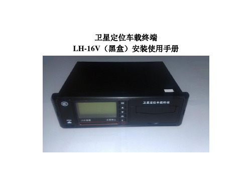
卫星定位车载终端LH-16V(黑盒)安装使用手册声明深圳市翰盛通讯设备有限公司版权所有,保留所有权利此手册仅供安装人员及客服人员使用。
请详细阅读功能说明并请妥善保存,以免遗失。
未经深圳市翰盛通讯设备有限公司明确许可,任何单位或个人不得擅自仿制、复制、誊抄或转译本册部分或全部内容。
不得以任何形式或任何方式(电子、机械、影印、录制或其它方式)进行商品传播或用于任何商业、赢利目的。
相关文档除本安装手册外,如需获取最新产品资料或不明之处,请登录http://一、车载终端整机接线说明图1 1.手柄口2.主线接口接线说明:3.图采口图5图采1到图采4接口功能说明注意:图采1到图采4输出12V电压,需要接12V供电的专用模拟摄像头,切勿连接平时使用的702、706数字摄像头及W2等5V电压的外设,以防烧坏。
4.透传口图4接口功能说明(1)默认为行驶记录仪模式,可接串口线通过2012行驶记录采集软件采集行驶记录数据。
(2)透传口模式下接文字播报器W2,实现调度消息TTS播报功能。
5.视频输出Video Out 模拟信号视频输出,接模拟信号显示屏。
6.SIM插口SIM插口为3G SIM 卡插口,底座的SIM卡座为GSM卡座。
7.TF卡插口(1)前面板有3个TF卡插口,上方两个为存储视频文件的TF插口,由下至上分别为TF卡1、TF卡2;(2)USB接口下方为提取行驶记录仪数据的TF插口。
二、注意事项(1)根据安装车辆类型,须准备齐全拆卸相应车辆仪表台或外设的工具。
(2)每安装1台终端须备1张已经确认开通移动GPRS网络(走CMNET公网或APN专网,走CMWAP网络的GPRS卡不可用)的SIM卡。
(3)获知SIM卡号的通讯号并网络中心注册。
(4)安装完毕后须将原车辆复原。
(5)安装时对终端接原车电源线应选择24小时通电的主干路电路,应不破坏原车电路。
(6)图采1到图采4供电电压为12V,不可以外接W2和SPK2等5V电压的外设,以防烧坏外设,此类外设应接在透传口。

ACC控制器用户手册安装、编程及操作说明书2006年2月初稿ACC用户手册B版第1页,共 47页ACC用户手册简介 (2)控制器接口以及关键组件 (2)连线箱内部视图 (2)符号释义: (2)安装 (2)金属箱,壁挂式安装 (2)连接交流主电源,墙挂式配电箱 (2)金属柜,可选基座式安装 (2)金属基座交流主电源的连接 (2)安装塑料基座 (2)连接塑料基座交流主电源 (2)接地 (2)站点模块的安装 (2)阀门线路的连接 (2)解码器输出线路连接 (2)解码器程序设置 (2)24VAC 测试终端(恒压24V): (2)总阀和/或泵起动继电器的连接 (2)降雨或冰冻关闭设备的连接(可选或未配备) (2)连接亨特流量传感器(非随机配备的可选项) (2)ICR 远程控制 (2)控制器程序设置及运行 (2)使用“信息”按钮 (2)设置当前日期和时间 (2)设置程序开始时间 (2)设置程序开始时间 (2)站点运行持续时间设置 (2)设置站点灌溉持续时间 (2)更改季节性调整 (2)设定灌溉日 (2)水泵和总阀运行设置 (2)水泵和总阀运行设置 (2)站点周期和浸水持续时间设置 (2)站点周期和浸水持续时间设置 (2)流量监视设置: (28)Clik™传感器运行设置: (2)传感器报警 (2)设置程序重叠选项 (2)ACC用户手册B版第2页,共 47页选项一:堆叠或重叠 (33)选项二:Smartstack™ (2)选项三:SSG/Smartstack (2)设置站点&程序名称 (2)数据历史记录 (2)隐藏功能 (36)无水窗口(信息+程序开始时间设置) (2)站点“信息+设置站点运行时间”之间的延迟 (37)让M/V 电路在常态断开(信息+设置水泵运行) (2)设置流量传感器型号和和类型(信息+设置流量监视) (38)SSG(同时站点群)设置(信息+重叠) (2)自定义手动操作程序设置(信息+手动操作) (2)启动自定义手动操作 (42)启动自定义手动操作: (2)测试程序:程序按钮(按下) (2)简易检索( Retrieve™)备分(信息+运行位置的程序按钮) (44)手动操作 (44)系统关闭 (2)复位 (45)故障排除 (46)规格 (47)尺寸 (47)电气 (2)ACC用户手册B版第3页,共 47页简介享特公司的很多模块化配置中,ACC控制器是工业级的高级控制器,用于高性能的灌溉控制。

DSG & DMG SeriesIncremental Linear EncodersInstallation GuideFor Models:DSG-TT, DSG-EV, DSG-EM DMG-TT,DMG-EV, DMG-EMContentsnewall Measurement systems2Contents1.Introduction1.1Brackets 1.2Preparation 1.3Warnings2.technical specification2.1Cable Connections 2.2Output Signals 2.3Resolution Options2.4Maximum T raverse Rates2.5Recommended Encoder Connections2.6DSG-EM/EV & DMG-EM/EV Interface Module3.DsG encoder Assembly4. DMG encoder Assembly5. Mounting the Reader Head5.1DSG 5.2DMG6.Mounting the scales and support Brackets6.1DSG 6.1.1 Double End Mounting 6.1.2 Single End Mounting6.1.3Encoders in Excess of 2.5 meters6.1.4Center Supports For Scales in Excess of 2.5 meters6.2DMG6.2.1 Single End Mounting7.Fitting the scale Guard 8.Cable Routing 9.Final Check10.scale Bracket orientation options 11.Dimension DrawingsIntroduction1.0IntRoDuCtIonThis manual will provide mounting instructions for Newall's DSG and DMG Incremental Linear Encoders. It isimportant that you read and understand this manual prior to beginning the installation.If at any time during the installation you should have any questions, contact Newall or your local authorised representative.1.1BracketsDue to the variety of machine types and applications, it may be necessary to design, make and fit custom bracketsfor the encoder assembly. If brackets are needed, make certain they are rigid enough to prevent any flexing ordistorting while the machine is in operation. Newall offers a variety of bracket kits to aid in the installation.Contact Newall or your local authorised representative for details.1.2PreparationPrior to beginning the installation the machine should be studied to determine where the encoder(s) will be fitted.For best results, it is recommended that the encoder be fitted as close to the machine lead screw or axial driveshaft as possible.DSG: Overall Length = T ravel + 258mm (10.2”)DMG: Overall Length = T ravel + 187mm (7.4”)Outboard mounting of the scale support brackets will add approximately 20mm (3/4") to the stated travel. (Referto Section 10.0)For a more compact installation, scale travels of 300mm (12") or less may be fitted by supporting one end of thescale only by use of a single end mounting block. (Refer to Figure 6.4 and 6.10)It is prefered the moving member of the encoder assembly is the reader head; the scale can be the movingmember but only on certain applications.Cable routing from the reader head should be examined (see section 7). Extension cables are available in a varietyof lengths. Contact Newall or your local authorised representative for further details.For encoders larger than 1500mm (60”) travel, a setup tube (blank scale) is recommended.1.3WarningsIf for any reason the machine axis travel is greater than the actual scale travel it is recommended that mechanicalstops are fitted to the machine to avoid damage caused by over-travel. Newall will not accept responsibility forscale and reader head damage caused by machine over-travel.Both the reader head and the scale are precision made components and it is important that they are handled withcare. By design the encoders can withstand the rigours of the harsh workshop environment. However, permanent damage can occur through bending or severe impact.It is important that the scale be kept at least 13mm (0.5") away from any magnetic bases on indicators or magnetic chucks.DSG and DMG encoders are designed to operate with Digital Readout Systems and therefore may not operatecorrectly with automated or closed loop motion control systems. For closed loop motion control applicationsplease refer to SHG & MHG encodersnewall Measurement systems3technical specificationCertificate No FM360964newall Measurement systemsCable Connections2.1 CABLE CONNECTIONSThe following pin out details apply to DSG-TT/EV/EM, DMG-TT/EV/EMNote: Pin 1 (Orange wire) is used during manufacture and should either not be connected or tied to 0V .2.2 Output Signals2.2.1 DSG-TT and DMG-TTNewall TT series linear encoders provide a differential quadrature output at RS422 TTL levels.The distance between successive edges of the combined pulse train A and B is one measuring step (resolution)2.2.2 DSG-EV/EM and DMG-EV/EMNewall EV & EM series linear encoders provide differential sinusoidal output signals, (via an external module), that are phase shifted by 90°, and can provide 1Vpp or 11µApp signal levels depending on which model is selected.No reference mark is provided with the DSG or DMG range of encoders.newall Measurement systems5technical specificationThe DSG and DMG encoders have a maximum output rate of 1MHz.250kHz Channel frequency500ns min6newall Measurement systemsCable Connections 2.5 Recommended Encoder ConnectionsTTL levels.1Vpp SVV Interface Module (Part No: 600-83640)11µApp SVM Interface Module( Part no: 600-83650)encoder AssemblyMounting the Reader HeadFigure 5.1 - Alignment of the DSG Reader HeadFinal adjustments can be carried out by use of laminated shims, which are included with each encoder assembly. Each layer of shim is equivalent to 0.05mm (0.002").5.2DMGFigure 5.2 - Alignment of the DMG Reader HeadMount the reader head together with its bracket(s) to the machine and secure the assembly parallel with axis travel to within 0.05mm (0.002"). (Refer to Figure 5.2)newall Measurement systemsnotes:Erroneous readings will occur if the reader head is allowed to travel beyond the effective travel limits. (Refer to Figure 6.1)The pre-load on the balls are factory set via the set screw at the tensioner end. Do not tamper with or adjust the set screw as this will alter the calibration and accuracy specification of the scale. (Refer to Figure 6.1)Once the reader head is secured and correctly aligned, the scale support brackets can now be fitted. The scale support brackets consist of the support pin, the support link and the pillar(s).raverse the machine to its maximum position toward the non-cable entry side of the reader head. Maximum position means all available travel, including hand winding past any electrical limits or trip dogs.Carefully slide the blank scale (or DSG scale if less than 1500mm (60") travel), allowing for a sufficient amount of scale to project from the reader head in order to fit the scale support brackets.Assemble the scale support link to the scale support pin leaving approximately 3mm (1/8") gap between the bottom of the pin shoulder and the top of the link.Slide the link/pin assembly onto the scale to approximately 5mm (0.2") away from the end of the reader head. Mounting the scalenewall Measurement systems10Figure 6.1 - DSG ScaleFIXED ENDTENSIONER END16mm EFFECTIVE TRAVEL LIMITS 30mmMounting the scale A maximum of two support pillars may be screwed together to allow for sufficient adjustment of the scale. If twopillars are insufficient to enable the scale to be mounted, then additional brackets will be necessary. These bracketsmust be sufficiently rigid to prevent any axial movement of the scale.Loosely fit the support link/pin assembly onto the pillar and pass the scale through the reader head and into thesupport pin. While gently sliding the scale forward and back 25 - 50mm (1" - 2") through the support pin, carefullytighten the hex screws on the support link, ensuring that the scale slides smoothly through the reader head and intothe support pin. If any interference is detected then fully loosen the hex screws on the support link and repeat this step.note: Do not force the scale through the support pinFigure 6.2 - Reader Head and Bracket AlignmentRemove the scale from the reader head and traverse the machine to its full extent in the opposite direction. Full extent means hand winding past electrical limits.Assemble the scale support link to the scale support pin leaving approximately 3mm (1/8") gap between the bottom ofthe pin shoulder and the top of the link.Slide the link/pin assembly onto the scale making certain that there is sufficient clearance between the reader head andthe support link to prevent damage to the reader head cable. Do not secure the support pin to the scale at this time.T ransfer punch through the support link and into the machine casting. It is important that the support link be kept square to its mounting surface at all times.newall Measurement systems11A maximum of two support pillars may be screwed together to allow for sufficient adjustment of the scale. If two pillars are insufficient to enable the scale to be mounted, then additional brackets will be necessary. These brackets must be sufficiently rigid to prevent any axial or radial movement of the scale.Loosely fit the support link/pin assembly onto the pillar and pass the scale through the reader head and into the support pin. While gently sliding the scale forward and back 25 - 50mm (1" - 2") through the support pin, carefully tighten the hex screws on the support link, ensuring that the scale slides smoothly through the reader head and into the support pin. If any interference is detected then fully loosen the hex screws on the support link and repeat this step.Repeat the above steps at the other end of the machine. Then carefully slide the DSG Scale through the support pin,through the reader head and into the opposite support pin. Tighten the hex screws on the anchor pins.6.1.2single end Mounting note: the maximum total length of the scale must not exceed 610mm (24") when using a singleend mounting kit. the single end mounting kit is sold separately, ask for part number600-63610.Remove the white rivet from the fixed end of the scale, by prying out with a straight edge screwdriver/tool.After the reader head has been installed slide the scale through the reader head and insert the fixed end of the scale into the single end mounting block. (Refer to Figure 6.4)Once the position for the single end mounting block has been determined mark the machine casting using the slot in the mounting block as the guide . Drill and tap M6 x 12mm deep. Fit the mounting block using the M6 socket head cap screw and washer.Check the alignment by gently sliding the scale through the head and in and out of the mounting block, adjustments may be carried out by altering the M5 jacking screws. When the alignment is complete secure the scale by inserting the M5 screw and washer through the mounting block and into the fixed end of the scale.Mounting the scalenewall Measurement systems12Figure 6.3 - Support PillarsMounting the scaleMounting the scale newall Measurement systems14Figure 6.5 - Long Scale Support Bracket Assembly6.1.4Center supports for scales in excess of 2.5 Meters (100”) travelSee data sheet supplied with center supports kit 600-84605Mounting the scale The scale support brackets kit consists of the Anchor Pin, Support Pin , Support Link, and Pillar(s). (Refer to Figure6.8) In order to avoid the risk of damage to the scale during installation all DMG encoders include a set up bar. Theset up bar is of the same diameter as the DMG Scale and will be used to align the brackets to the reader head.Figure 6.8 - DMG Scale Support BracketT raverse the machine to its maximum position toward the non-cable entry side of the reader head. Maximum position means all available travel, including hand winding past any electrical limits or trip dogs.Carefully slide the DMG Scale set-up bar through the reader head, allowing for sufficient scale to project from thereader head in order to fit the scale support brackets.Assemble the support link to the anchor pin leaving approximately 3mm (1/8") gap between the bottom of the anchor shoulder and the top of the link.Slide the link/anchor assembly onto the scale set-up bar to approximately 5mm (0.2") away from the end of the reader head.T ransfer punch through the support link and into the machine casting. It is important that the support link be kept square to its mounting surface at all times.Remove the link/anchor assembly and the scale set-up bar from the reader head. Drill and tap M6 x 12mm deep holeinto the machine casting as marked by the transfer punch. Fit the pillar(s) to the machine casting by using one of the methods shown in Figure 6.3. The pillar shoulder fits square and flush to the machine surface.A maximum of two support pillars may be screwed together to allow for sufficient adjustment of the scale.If two pillars are insufficient to enable the scale to be mounted, then additional brackets will be necessary. These brackets must be sufficiently rigid to prevent any axial movement of the scale.Loosely fit the support link/anchor assembly onto the pillar and pass the scale set-up bar through the reader head andinto the anchor pin. While gently sliding the scale set-up bar in and out of the anchor pin, carefully tighten the capscrews on the support link, ensuring that the scale set-up bar slides smoothly through the reader head and into the anchor pin. If any interference is detected then fully loosen the cap screws on the support link and repeat this step.Remove the scale set-up bar from the reader head and traverse the machine to its full extent in the opposite direction. Full extent means hand winding past electrical limits.Assemble the scale support link to the support pin leaving approximately 3mm (1/8") gap between the bottom of the mounting shoulder and the top of the link. (Refer to Figure 6.8)newall Measurement systems15Mounting the scale newall Measurement systems 16Slide the link/pin assembly onto the scale set-up bar making certain that there is sufficient clearance between the reader head and the support link to prevent damage to the reader head cable. Do not secure the support pin to the scale at this time.T ransfer punch through the support link and into the machine casting. It is important that the support link be kept square to its mounting surface at all times.Remove the link/pin assembly and the scale from the reader head. Drill and tap M6 x 12mm deep into the machine casting as marked by the transfer punch. Fit the pillar(s) to the machine casting by using one of the methods shown in Figure 6.3. The pillar shoulder fit square and flush to the machine surface.Loosely fit the support link/pin assembly onto the pillar and pass the scale set-up bar through the reader head and into the support pin. While gently sliding the set-up bar forward and back 25 - 50mm (1" - 2") through the support mounting, carefully tighten the screws on the support link, ensuring that the scale set-up bar slides smoothly through the reader head and into the support pin. If any interference is detected then fully loosen the screws on the support link and repeat this step.Carefully slide the DMG Scale through the support pin, ensuring the fixed end is inserted first, through the reader head and into the anchor pin.Using the M3 x 16 skt cap screw and spring washer, secure the scale to the anchor pin. It is important that the nylon set screw on the support pin be only “pinched” to the scale at the tensioner end. DO NOT OVER TIGHTEN THENYLON SET SCREW ON THE SUPPORT PIN. Figure 6.9 - Reader Head and Bracket AlignmentMounting the scale / Fitting the scale GuardFitting the scale Guard / Cable Routing / Final Check newall Measurement systems18Figure 7.1 - Fitting the Scale Guard (example shown using a DSG Scale)8.0 CABLe RoutInGThe most important and the most over looked aspect of fitting the encoder is proper cable routing. Dangling and loose cables can be snagged or broken causing irreparable damage. Care should be taken in order to ensure that the cables are secured to the machine and that cable loops do not interfere with any part of the machine or the encoder movements. "P" clips and thread forming screws are provided to route the cables.note: the armoured cable is an integral part of the reader head. If the cable becomes damaged,then it would have to be replaced complete with the reader head.If extension cables are used, do not allow the plug and socket junction to lie in the swarf tray or in the direct flow of coolant or oil.In order to avoid problems associated with electrical noise and interference, do not allow the cables to lie across electrical motors, fuse boxes or electrical pumps.9.0FInAL CHeCkPrior to putting the encoder into operation, slowly traverse the machine axis to both extents of its travel checking at all times that the cables are secure and that machine over travel cannot occur. Newall will not accept responsibility for encoder malfunction caused by over travel or damaged cables.scale Bracket orientation 10.0 sCALe BRACket oRIentAtIon oPtIonsnewall Measurement systems 20newall Measurement systems21newall Measurement systems22notes newall Measurement systems23EUROPENewall Measurement Systems Ltd. Technology Gateway, Cornwall Road South Wigston, Leicester LE18 4XH United KingdomTel: +44 (0) 116 264 2730***************.ukAMERICASNewall Electronics Inc.1803 O’Brien RdColumbus, Ohio 43228 USATel: +1 614 771 0213CHINA & TAIWANSensata Technologies China Co., Ltd.BM Intercontinental Business Center 30th Floor100 Yu Tong RoadShanghai 200070People’s Republic of ChinaTel: +86 212 2306 1500SINGAPORE AND KOREA Sensata Technologies Co., Ltd.3 Bishan Place #02-04Singapore 579838Tel: +65 647 86 867JAPANSensata Technologies Japan Ltd. Shin Yokohama Square Bldg, 7F2-3-12 Shin-Yakohama, Kohoku-ku Yokahama-shiKanagawa 222-0033 JapanTel: +81 45 277 7120For more information about this or any of our productsplease contact us at****************or visit DSGDMG1016ENUS023-82220-UK/0。

* Not included / sold separately.8 channel configuration shown. 16 channel will have the respective number of video inputs. Product image might appear different than the actual product. For camera compatibility information, visit /compatibility .Quick Start GuidesPower CableHDMI CableNeed Help?Visit us online for up-to-date software andcomplete instruction manualsVisit Search for the model numberof your productClick an individual channel to view it in full-Right-click anywhere on the screen to open the Quick Menu. LHV5100W_QCG_EN_R1and select Quick Access to System InformationTo quickly open a window that displays vital system information such as device ID, firmware version and device IP address:• Press the ENTER button on the front panel.• Right-click to open the Quick Menu and click Info . If prompted, enter the system user name (default: admin ) and your new, secure password.ORUse the drop-down menus to select the channels you would like to playback. Click the display options ( 321Configuring Deterrence SettingsIn live view, right-click and clickLog in using the system user name (default: your new, secure password. Clickand select Setting Click Event > Motion > Deterrence (see Figure 1).Select the channel of the deterrence camera to configure next to Camera .Click the Enable checkbox to enable automatic warning light deterrence.Click Setup next to Area to set the active area forautomatic deterrence:• The camera image appears with a grid of green boxes over top. The green area is the active area for deterrence. • Click or click-and-drag to add / remove boxes from the active area.• In Figure 2, only motion around the doorway will trigger warning light.To configure automatic deterrence using DVR:Set preferences for the automatic warning light triggering on compatible Lorex deterrence cameras. For a complete list of compatible deterrence cameras, see To activate deterrence features manually:Press and hold on the front panel for 5seconds. Warning lights and sirens will be activated for all connected deterrence cameras.Figure 1: Deterrence TabFigure 2: Deterrence Active Area ExampleEnter a time for the white light to be active up to 30 seconds.for a flashing light. •From live display, hover near the top of a channel to reveal the Mini Menu. Click to activate warning light, or click to activate siren.。

Level 2 Electric Vehicle Charging StationCat. No. EVB32Installation InstructionsWARNINGS AND CAUTIONS:• If the information in this instruction sheet is not followed exactly, SHOCK OR FIRE MAY RESULT CAUSING PROPERTY DAMAGE, PERSONAL INJURY OR DEATH .• For outdoor installations, hard wire connection is required to maintain NEMA 4 weatherproof rating.• Hard-wire installation and service must be performed by an electrician.• IMPORTANT: Save these instructions for local electrical inspector’s use and future reference.NOTE: Unit operates on 208V or 240V circuit, it will not operate on 120V.DI-040-EVB32-00BThank you for purchasing the Level 2 32A Electric Vehicle Charging Station. This installation sheet includes the latest information at the time of printing. Leviton reserves the right to make changes to this product without further notice. Changes or modifications to this product by other than an authorized service provider could void the product warranty. If you have questions about the use of this product, contact your Customer Service Representative. Refer to the Customer Support section located in these instructions.MOUNTING LOCATIONThe charging station should be located in close proximity to the electric vehicle’s parking location. The charging station must connect to the electric vehicle via a charge connector and chargeconnector cord. Note: the path from the charging station to the electric vehicle should be free from obstacles, and be within the range of the charge connector cord (18 or 25 foot standard lengths).The recommended mounting height of the charging station is not to exceed 48 inches, but not less than 42 inches. This provides convenient access and operation of the charging station, and meets ada requirements for access.NOTE: the area surrounding the charging station enclosure should be free from obstruction. Recommended clearance around station: 5" above and 3-1/2" on either side.MOUNTING INSTALLATIONSelect a location that is suitable for mounting the charging station based on the criteria presented in the MOUNTING LOCATION section.For stud walls, the charging station can be mounted to bare studs or walls with drywall.For metal stud or solid wall applications, you will need to procure wall anchors for the charging station, capable of supporting a maximum allowable load of 200 lbs. For solid wall applications you will also need to procure appropriate conduit and appropriate wall anchors.NOTE: A hard-wired installation can be mounted directly to the wall, or with the use of the mounting bracket included in the Pre-Wire Kit (purchased separately).To mount directly to a stud wall, follow directions below:NOTE: Prior to a plug-in installation, assure the following items have been purchased:• NEMA 6-50 plug (Leviton Cat. No. 9650-P)• 18.5 inches of type SOOW cord with three 8 AWG wires (nominal O.D. 0.845")• Strain relief suitable for cord (i.e. Heyco part no. M4348)• Leviton Pre-Wire KitNOTE: The Plug-In Charging Station must be installed with a Leviton Pre-Wire Kit (soldseparately). Failure to do so means the station no longer complies with its UL listing. The listing requires the station be removable without tools. Refer to Pre-Wire Kit instructions first if a mounting location has not been established.NOTE: A molded 6-50P power cord can be used, as long as the cord length is 18.5".If the SOOW cord and the NEMA 6-50 plug are purchased separately, assemble them per the NEMA 6-50 plug manufacturer's instructions. 1. Remove 6" of jacket from the cord's free end.2. Use a standard flat blade screwdriver to open the enclosure door from the side to gain access.3. Remove plug from bottom of charging station enclosure.4. Insert strain relief into the hole at bottom of enclosure, ensuring rubber washer is installedbetween strain relief and metal surface of enclosure. Secure strain relief in place with locknut and torque to 66 in-lb.5. Insert the cord through the strain relief, leaving 12" of cord outside of the enclosure.6. Tighten the strain relief dome nut to 95 ± 2 in-lb.7. Strip ground wire 1/2" and line wires 3/8". Insert line wires (a and b ) into the terminal blockabove the strain relief. Torque to 16 in-lb. (see figure 4). Insert the ground wire (c ) into the ground lug (see figure 4). Refer to table 1 for proper torque values.8. Close enclosure door and secure lock with flat blade screwdriver. Place warranty void padlockonto the locking tab (see figure 5).9. Locate the slot above the thumb screw. Locate the four mounting buttons on the back of thecharging station (see figure 1).10. Align the slot with the guide pin, and the four mounting buttons with the four key holes on themounting bracket (NOTE: Bracket is mounted per Pre-Wire Kit instructions).11. Once aligned, gently press the charging station onto the mounting bracket.12. Allow the charging station to slowly slide down into place.13. Tighten the thumb screw to secure charging station to mounting bracket.Proceed to POWER CHARGING STATION section.RATINGS120/208V 60Hz 3-phase Y (L1-G/L2-G - 120V, L1-L2 – 208V)120/240V 60Hz Split-phase (L1-G/L2-G - 120V, L1-L2 – 240V)32AVoltage CurrentNOTE: Charging Station operates on 120/208V or 120/240V circuit only. Does not operate on 120V circuit.Gather the required tools and parts before starting installation. Be sure to follow manufacturer’s instructions for use of any tools or parts used for this installation.Tools:• Drill with 3/16" bit • Stud finder• Level• Scratch awl • #2 and #3 Phillips screwdriver • Utility knife • Measuring tape• Wire cutters/strippers• Keyhole saw Additional Parts (not included):• Copper electrical cable• Conduit(8 AWG minimum, 19 Strands maximum) • Strain relief (if applicable)• 40A Circuit Breaker• H100-TB Hub• #14 wood mounting screws (2) - stud mount(or engineering equivalent)For Metal Stud Applications:• Wall anchors capable of supporting a maximum allowable load of 200 lbs.For Solid Wall Applications:• Wall anchors capable of supporting a maximum allowable load of 200 lbs. • Appropriate conduit and applicable mounting hardware.HARD-WIRE INSTALLATIONImportant Notes to the Installer:• Read all instructions contained in these installation instructions before installing hard-wiredversion of the charging station.• The installer is responsible for verifying that the wall structure/surface will safely support a totalload of 200 lbs.• Observe all governing codes and ordinances.• Be sure to leave these instructions with the consumer.Important Notes to the Consumer:• Keep these instructions with your user guide for future reference.• Ensure your charging station is installed properly by an electrician or service technician.TO INSTALL:1. To install the charging station by use of mounting screws, first remove the 4 mounting buttonsfrom the charging station (see figure 1 rear view).2. Locate a wall stud in the area in which the charging station will be installed (see figure 2).3. Measure 48" up from the floor and place a mark on the stud that will be used for mounting.4. For wood studs, drill a 3/16" diameter pilot hole, 2-1/2" deep, directly in the middle of the stud.For metal studs, follow manufacturer’s instructions for wall anchor installation.5. Loosely fasten a #14 x 2-1/2" wood screw by turning the screw into the pilot hole untilapproximately 1/2" length remains. Hook the charging station onto the screw using the mounting tab. Secure in place by installing an additional screw through the bottom set screw hole.6. T ighten top mounting screw. Proceed with Hard-Wiring Charging Station.WARN ING: HARD-WIRE INSTALLATION AND SERVICE MUST BE PERFORMED BY AN ELECTRICIAN.WARNING: TO AVOID FIRE, SHOCK, OR DEATH TURN OFF POWER AT CIRCUIT BREAKER OR FUSE AND TEST THAT POWER IS OFF BEFORE WIRING!CAUTION: USE THIS DEVICE WITH COPPER OR COPPER CLAD WIRE ONLY .CAUTION: A 40A BREAKER SHALL BE USED. DO NOT USE WIRE LESS THAN 8 AWG REFER TO TABLE 1 FOR PROPER TORQUE VALUES.1. If necessary use a standard screwdriver to open the Enclosure Door from the side to gainaccess for wiring.2. Loosen terminal block screws for Line and Ground wires. Remove pre-installed hub anddisconnect existing plug assembly. Install a 1" NPT hub (or engineering equivalent).3. Verify that appropriate circuit breaker, conduit and wire gauge have been selected.4. Run an individual circuit as per the National Electric Code and local building codes. The circuitmust reach the bottom of the Charging Station with an additional 5" of loose wire to terminate the connection on the inside of Charging Station.NOTE: Use appropriate strain relief for conduit if applicable.5. Feed conduit through hub. Leave approximately 5" of wire lead in the Charging Station. Secureconduit to hub using proper conduit fitting. The use of a reducer may be required based on conduit fitting selected (see Figure 3).6. Strip Ground wire 1/2" and Line wires 3/8". Insert Line wires (A and B ) into the terminal blockdirectly above the hub, torque to 16 in*lb (see figure 4). Insert the Ground wire (C ) into the terminal block to the right of the hub (see figure 4). Refer to TABLE 1 for proper torque values.7. Close Enclosure Door and secure lock with screwdriver. Place new Warranty Void Padlock ontothe locking tab (see Figure 5).HARD-WIRING CHARGING STATIONFor more information call 1-877-338-7473 or visit /evrgreen For warranty information and/or product returns, residents of Canada should contact Leviton in writing at Leviton Manufacturing of Canada Ltd to the attention of the Quality Assurance Department, 165 Hymus Blvd, Pointe-Claire (Quebec), Canada H9R 1E9 or by telephone at 1 800 405-5320.DI-040-EVB32-00BLIMITED 3 YEAR WARRANTY AND EXCLUSIONSLeviton warrants to the original consumer purchaser and not for the benefit of anyone else that this product at the time of its sale by Leviton is free of defects in materials and workmanship under normal and proper use for three years from the purchase date. Leviton’s only obligation is to correct such defects by repair or replacement, at its option. For details visit or call 1-800-824-3005. This warranty excludes and there is disclaimed liability for labor for removal of this product or reinstallation. This warranty is void if this product is installed improperly or in an improper environment, overloaded, misused, opened, abused, or altered in any manner, or is not used under normal operating conditions or not in accordance with any labels or instructions. There are no other or implied warranties of any kind, including merchantability and fitness for a particular purpose , but if any implied warranty is required by the applicable jurisdiction, the duration of any such implied warranty, including merchantability and fitness for a particular purpose, is limited to three years. Leviton is not liable for incidental, indirect, special, or consequential damages, including without limitation, damage to, or loss of use of, any equipment, lost sales or profits or delay or failure to perform this warranty obligation. The remedies provided herein are the exclusive remedies under this warranty, whether based on contract, tort or otherwise.POWER CHARGING STATIONNOTE: F or Hard-Wire Installation , restore power at circuit breaker or fuse.For Plug-In Installation , simply plug the AC Supply Cord into the NEMA 6-50R grounded 50A, 240VAC electrical outlet supplied with the pre-wire kit and in good working condition to start power up sequence.Power Up Sequence• The Power, Charging and Fault LEDs will illuminate momentarily followed by just the Power LED. The Charging Station will then initiate a self-test sequence.NOTE: DO NOT plug the Charge Connector into the vehicle prior to the self-test; this may cause the Charging Station to go into Cold Load Pick-up, and delay charging.• The Power LED will flash for approximately 3 seconds indicating the self-test, and then the Power LED will remain lit, indicating that the Charging Station is ready for use.Refer to Level 2, 32A Electric Vehicle Charging Station User Guide for operation.© 2016 Leviton Mfg. Co., Inc.CUSTOMER SUPPORTFOR CANADA ONLYCall our Customer Support Hotline at 1-877-338-7473. If your call is made after business hours or on weekends, please leave your name, telephone number, the unit’s serial number, and a brief description of the problem. These can be found on the label on the left side of the Charging Station enclosure. A Customer Service Representative will call back at the earliest opportunity. Many questions and answers can be found in our knowledge base community. Just go to and click on the Knowledgebase link, or go directly to /evrgreen.TRADEMARK DISCLAIMER: Use herein of third party trademarks, service marks, trade names, brand names and/or product names are for informational purposes only, are/may be the trademarks of their respective owners; such use is not meant to imply affiliation, sponsorship, or endorsement.。
C-NaviGator IIC-NaviGator II Control and Display UnitFigure 1: C-NaviGator II Display (Front View)Figure 2: C-NaviGator II Side-panel ConnectorsFigure 3: C-NaviGator II Power SupplyMechanical SpecificationsSize (L x W x H) 82.2mm (3.2”) x 340mm (13.4”) x 260mm (10.2”)lbs)kg(10.6Weight4.8Display 10.4” TFT LCD, 1024x768, 400 nit, Resistive TSCPU 1.0 GHz VIA 7C, 512 MB, 2GB CFPower Input SpecificationsInput Voltage 12 VDC +/- 5% (24-12VDC converter available)30WConsumptionPower SupplySize (L x W x H) 31mm (1.2”) x 110mm (4.3”) x 62mm (2.4”)16282-2SG-311Micro-Con-XConnectorConxall,Input Voltage 90 – 264 VACPower 60 W63Hz-47FrequencyOutput Voltage 12 VDC (+/- 5%)Operating Temperature 0º C ~ +40º CStorage Temperature -20º C ~ +65º CHumidity Operating: 20 ~ 80% RH; Storage: 10 ~ 90% RHConnectors17282-2PG-300Micro-Con-XConxall,PowerDCI/O Ports 4 x 9 pin RS-232 DBM (RS232-422 converter available) Keyboard/Mouse PS/2100/1000xMbps1LAN2.0xUSB2pinDBF15x1VGAPrinter, Parallel 1 x 25 pin DBFEnvironmental SpecificationsOperating Temperature 0º C to +60º CStorage Temperature -20º C to +85º CHumidity 5 - 90% @ 60º C, non-condensingC-NaviGator II Mounting OptionsOption #1: Allows mounting from ceiling, wall or desktop with fully adjustable positioning.Figure 4: RAM 100 75 VESA Base (w/ Steel Reinforce) / RAM-D-246U-IN1 This piece fits to the standard VESA mounting holes on the back of the C-NaviGator.Figure 5 RAM Double Socket ArmsRAM-D-201U-C / RAM Double Socket Arm SHORT (3.63”)RAM-D-201U / RAM Double Socket Arm MEDIUM (6.88”)RAM-D-201U-E / RAM Double Socket Arm LONG (11.75”)Choose from one of the arms above. We recommend the medium length.Figure 6: RAM 11" X 3" Base (w/ Steel Reinforce) / RAM-D-111B-IN1U (left) & RAM 3.68 DIA. BASE (w/ Steel Reinforce) / R AM-D-202U-IN1 (right)This piece is fixed to the ceiling, counter top or wall.Option #2: Desktop StandFigure 7: Flat Screen Table Stand (for C-NaviGator II) / CHIFSB018BLK Option #3: Wall MountFigure 8: Tilting VESA Wall Mount (for C-NaviGator II) / PEEST630Option #4: Front Panel MountUse this adaptor if unable to secure display from the back. Appropriate hardware is included to secure the C-NaviGator to the Front Panel Mount prior to mounting. Bolt thread size is M4 x6mmFigure 9: Front Mount Kit (for C-NaviGator II) / SYNIWO-6710-7CRBR2Option #5: 19” Rack MountUse this adaptor if installing the C-NaviGator to a rack. The 19” Rack Mount takes up 7U of rack space and is 12 ¼” in height. Appropriate hardware is included to secure the C-NaviGator to the Rack Mount prior to mounting. Bolt tread size is M4 x 6mmFigure 10: 19” Mounting Kit (for C-NaviGator II) / SYNIWO-6710-7CBR9Figure 11: C-NaviGator II (side USB-port model) Outline Diagram (mm) Both inside and outside mounting holes on vesa mount are M4 x 16mm in size.Inside holes have 75mm spacingOutside holes have 100mm spacingFigure 12: C-NaviGator II Cut-out Diagram (mm)Cut-out Panel includes hardware to facilitate bolting of the C-NaviGator from the rear via M4 x 16mm sized bolts (6 places) or from the front via M4 or #10 sized bolts (4 places, rev. A only)Figure 13C-NaviGator II rev. A (front USB-port model) Outline Diagram (mm)C-NaviGator II LCD Touchscreen Care and CleaningLCD screens are not like ordinary monitor screens in that they are not made of glass, rather they are made up of a soft film that can easily be damaged by abrasive cloth or paper, chloride and other chemicals found in ordinary tap water. LCD screens are delicate and they must be handled with the utmost care.Care and Cleaning Tips:• Turn off display before cleaning.• Use a commercial cleaner specially designed for LCD displays, such as Klear Screen (P/N: IK-8/MK-COM). If a commercial cleaner is unavailable, use distilled water as tap water may leave mineral spots. Eyeglass cleaner can also be used if absolutely necessary, however it may contain some alcohol, which could dry out thescreen and cause it to go cloudy.• Use a soft, lint-free, anti-static cloth such as eyeglass cloths, Microfiber cloth, Chamois, or a clean cotton T-shirt. Dampen cleaning cloth with your solution and apply very gentle pressure using a circular motion.• Ensure screen is thoroughly dry before powering on.Do not:• Spray cleaner directly on screen. It could possibly leak inside a non-sealed unit and cause damage.• Use solution that contains ammonia (e.g. Windex). It can etch the screen surface and cause the plastic to go cloudy.• Use paper towels, tissues, dish cloths. Paper products contain micro-particles of wood and will cause tiny scratches that you may not see, but will be harmful.。
GPS/北斗定位模块使用说明书适用产品系列/型号:LH-GPS-DM-485-A历史版本目录1.产品介绍 ------------------------------------------------------------------- - 2 -2.规格参数 ------------------------------------------------------------------- - 2 -3.产品尺寸 ------------------------------------------------------------------- - 3 -4.通信协议与数据格式 -------------------------------------------------------- - 4 -4.1.通信协议说明----------------------------------------------------------- - 4 -4.2.寄存器定义 ------------------------------------------------------------- - 5 -4.3.协议详解 --------------------------------------------------------------- - 7 -4.3.1.读取版本号 --------------------------------------------------------- - 7 -4.3.2.读取与修改设备地址 ------------------------------------------------ - 7 -4.3.3.读取与修改设备波特率---------------------------------------------- - 8 -4.3.4.读取与修改奇偶校验位---------------------------------------------- - 9 -4.3.5.读取定位数据(RMC)--------------------------------------------- - 10 -4.3.6.定位数据(RMC)解析--------------------------------------------- - 10 -5.接口说明 ------------------------------------------------------------------ - 12 -6.产品维护保养-------------------------------------------------------------- - 13 -6.1.设备使用环境---------------------------------------------------------- - 13 -6.2.常见问题与解决办法 --------------------------------------------------- - 13 -7.售后服务 ------------------------------------------------------------------ - 14 -7.1.售后服务承诺---------------------------------------------------------- - 14 -7.2.免责声明 -------------------------------------------------------------- - 14 -7.3.联系方式 -------------------------------------------------------------- - 14 -用户须知❖使用前请详细阅读本说明书,并保存以供参考。
一键启动主机/无钥匙进入/关窗器的找线方法1、常电电源线:正12V,在任何情况下都是12V,用万用表黑笔接地,红笔测,是12V的是常电线。
2、接地线:负-,在任何情况下都是负极,简称车身搭铁线。
3、ACC:用万用表黑笔接地,红笔测,钥匙打到ACC时是12V的是ACC线。
关闭钥匙后,这条线没任何反应为0V。
4、ON1线:用万用表黑笔接地,红笔测,钥匙打到ON挡时是12V的是ON1线。
(此线在点火过程中也是12V)。
关闭钥匙后,这条线没任何反应为0V。
5、ON2线:用万用表黑笔接地,红笔测,钥匙打到ON挡时是12V,点火时是0V的是ON2线。
(此线在点火过程中0V,点火启动后也是12V)。
关闭钥匙后,这条线没任何反应为0V。
6、点火启动线:用万用表黑笔接地,红笔测,钥匙打到ON时是0V,点火时是12V,点火成功后是0V。
关闭钥匙后,这条线没任何反应为0V。
7、发电机输出信号线:用万用表黑笔接地,红笔测,钥匙打到ON时是0-3V,点火成功后是12V。
关闭钥匙熄火后,这条线没任何反应为0V。
8、刹车线:在不插钥匙的情况下,用万用表黑笔接地,红笔测,踩刹车时有12V,松开刹车0V。
有些车要插钥匙才有信号,此种车请改接一年刹车开关的输入线到常电12V线。
9、中控锁触发方式及连线的判断:9.1负触发方式的判断:用测试笔固定夹一端接地(搭铁)。
触笔一端触试中控锁的两条控制线,中控锁若工作,该两条线是中控锁的负触发控制线。
9.2正触发方式的判断:用测试笔固定夹一端接电源,触笔一端触中控锁的两条控制线,中控锁若工作,该两条线是中控锁的正触发控制线。
9.3 正、负触发方式的判断:若用上面两种方法去判断中控锁都正作,这是正负触发方式。
9.4 单线串联负触发方式的判断:用电笔测只有一条线下锁,再找没有开锁线,而且剪断这根线会开锁。
9.5正负触发和正电回路判断都是一样的,有人说。
正负触发的不一定能用上正电回路。
它们判断方法都是在开锁或关锁时分别有两跟带正电的线,断开这两个可以接正负触发,但是不一定要用正电回路。
自适应巡航控制系统(ACC)自适应巡航控制系统传感器安装总图→相关章节。
关于自适应巡航控制系统的一般说明→相关章节用ACC 校准设备 -VAS 6190-进行校准的流程,见→相关章节。
用ACC 校准设备 -VAS 6430-进行校准的流程,见→相关章节。
拆卸和安装 ACC 传感器→相关章节。
自适应巡航控制系统传感器装配一览图1 -传感器拆卸和安装→相关章节2 -定位点用于直立销3 -插销提示支架中的立销是预调好的。
不允许改变其设定。
4 -支架5 -插头松开时挤压两个卡箍,如-箭头-所示。
1.2.ACC概述间距调节传感器和间距调节控制器 -J428-安装在一个壳体内。
传感器或控制器损坏时,必须整体更换。
以下描述时,传感器及控制器称为传感器。
传感器的雷达盖板位于前保险杠盖板后面,并由可通过雷达波的材料制成。
所有改变,如后来的喷漆、粘贴的标签等都可能导致功能故障。
传感器受到污染时也可导致功障碍。
为此请按照维修手册拆下传感器前的装饰格栅或散热器格栅,并清洁装饰格栅或散热器格栅的内侧和传感器。
在进行自适应巡航系统调节前,首先必须查询故障记忆并排除故障。
在 ACC 控制单元的测量值块 2中可识别,传感器是否仅略微移动,不超过° 的失调角不需要重新调校。
自适应巡航系统调校必须使用经大众 / 奥迪许可的四轮定位仪和调校装置进行!正确调校是保证 ACC 功能完好的前提。
提示以下情况需要重新正确调校:已调整过后桥前束。
已更换整个雷达传感器。
保险杠横梁已松开过或移动过。
前端上有损坏。
失调角大于°。
用 ACC 调校装置 -VAS 6190-进行校准需要用到的专用工具、检测仪器以及辅助工具车辆诊断、测量和信息系统 -VAS 5051 A-诊断导线 -VAS5051/5A-ACC 调校装置 -VAS6190-四轮定位仪提示在将车辆开到四轮定位仪上前,检查车辆与自适应巡航控制系统调校装置 -VAS 6190-之间是否有足够大的摆放位置。
洛阳隆华传热科技股份有限公司安装指导手册ACC(具有尖峰冷却装置)安装指导手册洛阳隆华电力事业部目录一、概述 (2)二、空冷凝汽器施工方法与步骤 (4)三、蒸发式凝汽器的安装 (16)四、管道及其附件的安装 (18)五、气密试验 (20)六、电气和仪表的安装 (20)七、其他 (20)八、安装结束 (21)一、概述此指导书为总体指导书,并不适合所有具体的安装情况,而请根据情况相应而定。
电厂的安装施工应由业主委托的一家或几家安装施工单位来完成。
安装应参照安装指导手册、洛阳隆华监督人员的特别指导、以及现场的施工规定来进行。
建议所有与洛阳隆华供货范围有关的技术问题需征询洛阳隆华监督人员或总部意见。
应特别注意有关的图纸和规定中所提出的要求。
安装指导书的内容并不能免除安装施工单位所必须履行的责任,他们必须是技术熟练的安装施工单位。
本指导手册的先决条件是安装施工单位应具有充分的安装此类电厂的经验。
安装施工单位不能据此安装指导书提出任何额外成本/费用,因为此指导书仅为总体指导书。
安装施工单位必须采用所有措施避免在存储、运输和安装过程中对已经交付(或已经预装配好)的设备造成任何损坏。
需要特别注意设备的接货,相关说明和手册将单独另外提供。
为了避免损失和意外,必须遵守现场的规章、避免意外事故的相关规定和国家的有关法规。
在电厂的预安装和安装阶段,必须提供安全带、脚手架、保护墙、帆布和相应的防护设施。
基本上,整个安装施工由下列内容构成:∙安装,检验,顺序计划以及检验单。
∙对图纸的注释。
∙焊接✧焊接工作和焊接检验应按照相应的焊接和检验计划进行。
必须指出的是,在焊接前施工单位应准备好焊接工序规范并且填写在焊接和检验计划表中。
必须首先经过洛阳隆华的焊接工程师的检查和认可后,现场的焊接工作才可以进行。
✧焊接工人必须具有从事该工种的职业证书。
✧所有焊接必须进行100%的目测检查。
✧所有对现场焊接所进行的检查必须符合相关的焊接和检验计划。
✧根据洛阳隆华的焊接和检验计划对相应部分实施X射线探伤检验。
∙当完成安装施工内容的最后一项内容即气密试验后,所有的焊缝根据项目规范进行充分的除锈,后应涂底漆和面漆。
安装施工单位的服务范围:∙所有材料的卸货、搬运和存储、包括间接存储或在现场直接吊装到位。
存储应遵循编码系统以便当需要安装时可以迅速查找到货物。
∙接货时根据交货清单确认部件的数量。
必须由安装施工单位与洛阳隆华的代表一起对所有材料的任何外观损伤进行检验。
材料验收报告(根据洛阳隆华的质量保证规范)、溢短装和损失报告应在材料运抵现场后马上完成。
∙存储场地到安装现场之间的运输。
∙对准备试运行前的所有部件的安装和就位找正。
∙各项测试和运行前的测试工作,比如完成凝汽器的安装后通过在排汽管道上加装盲板(如果没有其它指导的话)并采用压缩空气进行泄漏测试。
安装气密试验的临时设施并在完成气密试验后拆除。
∙提供特殊遮盖的存储设施用于需要露天防护的设备如仪表、焊接材料等。
∙现场安装人员的设施。
∙所有必备的工具和脚手架。
∙提供吊车和其他起重设备。
∙所有安装人员,包括总监,质量控制总监,熟练技术工人,仓库保管员和协助人员∙保护设备和急救服务。
∙针对所有意外的保险。
∙提供动力电源,临时照明,压缩空气和燃气,焊接设备,所有的焊条等。
∙对所有临时的结构和设施,施工方应负责提供、安装、和妥当维护以及在用户进行检验后拆除。
还应提供、安装、和保护好所有的运行设施,包括撤离后使现场整洁、安全并为整个电厂的运行做好准备。
∙所有安装工作需要的测试、质量检测工具和检测设备。
检测设备应附有校准证明书。
∙所有设备最后涂漆或者镀锌材料的修饰。
∙将设备和设施的运到和运离现场的运输工作。
现场要求:现场的设置和所有其它组织工作都由安装施工单位负责。
通常的和最重要的现场要求和应提供的服务如下:∙场地准备。
∙材料的接收、卸货和存储。
如果需要,应该在场外提供的储存区域。
∙所有不能马上安装的材料,应存放到存储区。
齿轮箱、电机、泵、真空泵、执行器等应存放在遮盖的储存区域。
检测仪表和其它精密设备应储存在干燥的地方。
∙由存放地到预组装场地之间的运输。
∙预组装。
∙设备部件的就位和安装,包括所有必须的基础的测量工作。
∙根据质量要求进行试验(包括对现场焊缝进行的X 射线检验)。
∙所有热交换器管束应该覆盖,加以保护,避免锈蚀。
∙部件在最终安装前应进行清洁检查,特别要检查是否有砂子或其它沉积物藏在管束和管箱中并将其除去。
建议配备大功率工业用真空吸尘器。
∙需要特别指出的是,建筑施工单位应对所有由于安装行为,特别是对于建筑物的(屋顶、围墙等)造成的损失负责二、空冷凝汽器施工方法与步骤空冷凝汽器的安装基本上由下列部分构成(具体内容根据图纸确定):∙支撑钢结构(钢桁架平台、风机密封板等)。
∙风筒和风机防护网。
∙风机平台结构和平台钢板(风机密封板)。
∙风机、风机桥架和风机驱动装置。
∙A型框架和隔墙。
∙换热器管束。
∙蒸汽分配管道。
∙蒸发式凝汽器。
∙排汽管道。
∙安全设备如爆破片、安全阀。
∙凝结水管路(包括凝结水系统的水箱等附件)。
∙抽真空管路(包括抽真空系统的相关连通管)。
∙小直径管路(包括清洗水系统)∙控制、仪表、电缆及其桥架。
∙保温(如需要)。
∙挡风墙。
∙防腐。
∙清洗装置(如需要)。
安装工序应该是按照先后顺序进行,若允许,可以交叉作业。
为了达到安装工作效率的最大化,必须确保所有有关各方安排好各自的现场工作,特别是起重工具的使用,必须与其它工作协调好。
起重机的起重能力可以根据图纸、现场位置安排和下表计算得出,最重要的设备的重量如下:∙管束重约(kg) :∙管束尺寸(长x宽x厚mm):∙蒸发式凝汽器重约(顶箱+上箱+下箱+风机 kg):∙蒸发式凝汽器顶箱(长x宽x厚mm):∙蒸发式凝汽器上箱(长x宽x厚mm):∙蒸发式凝汽器下箱(长x宽x厚mm):∙风机桥重约(kg) :∙风机重约(kg) :∙电机重约(kg) :∙齿轮箱重约(kg) :∙排气管道最重部分约(kg) :∙蒸汽分配管最重部分约(kg) :钢桁架部分可在地面进行部件的组装,其组装后的最大重量可根据起吊设备的最大起吊重量而定。
所有的起吊和起重设备须进行试验检定。
只能用合适负载的起重设备。
支撑结构(钢桁架),风筒和风机平台参考图纸:ACC总体布置图、支撑结构(钢桁架)图纸、风机安装图纸。
在开始任何工作之前,应特别确保在混凝土立柱周围搭建好脚手架,以便于在混凝土立柱顶部的进一步工作并有安全通道。
设备布置在汽机房附近的零米混凝土支撑结构上。
具体参见总体布置图。
应在混凝土立柱顶部用水平仪对混凝土支撑结构的高度进行控制。
在测量垂直梁长度时,应将衬板的厚度计算在内。
衬板被放置在混凝土支撑立柱和锚固构架的底板之间。
支撑结构又再分为下列不同部分:预组装的结构件(锚固构架、格状基架、框架)∙锚固构架: 锚固构架将被安装在支撑立柱的顶部,其高度应被仔细监测。
在一个支撑区域内的高度误差不应大于3mm。
建议在立柱顶端放置底板,它可以使得立柱顶端的高度更精确。
在立柱顶端上标注了主坐标之后,需要标注衬板的位置并用螺栓固定(如果没有提出其它要求的话)。
∙灌浆:在锚固结构和衬板都已经就位并找平和紧固后,应该进行灌浆。
我们建议灌浆与平台安装同步进行。
∙为了调整安装过程中额外的预应力对标高的影响,以及支撑表面的高度差,需要进行找平,不同厚度的调整垫片被放置到垫块上面。
典型的调整垫片的厚度是5mm、3mm和1mm。
在第一个部件安装之前,也就是说,管束、管道等被开始安装之前,应在所有立柱相应地在支撑梁上每隔4-5m标注基准点。
根据这些基准点,支撑立柱的柱头高度可以用经纬仪测量出来。
测量结果被记录在表格中,这样就可以在整个ACC安装的时间内控制调整ACC平台的高度,并且如果需要,可以重新找正。
进行重新找正时,需要使用液压千斤顶。
千斤顶应该放在固定底板和框架支柱之间。
必要时可在衬板顶部和框架支柱板之间放适当厚度的垫片。
当ACC平台和所有相关部件安装完成后,所有基准点的高度经过再一次测量并记录在案。
这些记录是安装全部完成后调整整个ACC平台的依据。
当ACC平台调整完成后,由洛阳隆华监督人员和客户共同确认之后,所有基准点的高度再一次进行测量和记录。
∙在衬板就位之后,刚桁架将在地面上预组装并吊运到平台结构框架上,然后被放置到支撑点上。
此时必须利用水平仪保证平台框架每一部分的高度符合要求,然后风机的安全防护网和支撑梁也安装就位。
∙在钢桁架的网格状支撑结构安装完成之后,再组装底部结构。
如下图平台钢结构的安装顺序钢结构安装程序列出。
管束的安装程序和钢结构的安装程序完全一致,因此在扇区风机单元的数字顺序也同样表明管束和其他设备安装顺序。
梯子(需要在地面预安装)平台引道需要根据整个ACC工程的安装进程进行安装。
∙蒸发式凝汽器体积大,质量大,安装位置高,吊装时吊车靠近蒸发式凝汽器平台。
风机单元的安装∙风机防护网托架必须全部在地面组装好(包括格栅),与风筒一块儿吊运并安装到风机平台的支撑结构上。
平台钢结构主框架(7)的安装在如前面所叙述的安装程序中实施。
∙将风机防护网支撑梁(6)和主框架(7)相连接。
∙在地面上将风机防护网(3)和托架(5)进行预组装。
风筒(4)保存在风机防护网(3)中只是为了便于运输。
用一个升降机可将含有风机防护网(3),托架(5)和风筒(4)的整体单元运到风机护网的最终位置,即风机防护网托架(5)和风机防护网支撑梁(6)相连接。
∙在平台顶部高度处,将水平支撑梁(2)连接到平台主框架(7)。
∙盖板(1)和水平支撑梁(2)以及位于钢结构顶部的平台主框架(7)相连接。
∙从风机防护网(3)处提升起风筒(4),并连接到盖板(1)下面∙风筒一般被拆分成若干段交货,它们必须在地面组装成一个整体。
圆度偏差必须保持在要求的公差范围内,否则扇叶顶部与风筒的接触擦碰会造成损坏。
风筒安装完毕后必须再一次检查风筒的圆度,如果需要的话再进行调整定位。
风机防护网拼装风筒拼装拼装完成的风筒和风机防护网对于风筒的安装,必须特别注意平台台板的准确就位。
风扇风口的中心和内径必须满足规定的公差、否则就无法实现风筒和其各段的无应力安装,并且在安装阶段和随后的运行阶段可能被损坏。
附图是对平台台板调整就位的原理图。
桥架的安装桥架由桥架本体、栏杆、踏板栅格等构成,并在预组装场地与电机、齿轮箱、风机轮毂和扇叶先预组装好。
预组装好后,整体被吊装的最终安装位置。
扇叶的安装和调整找正:详见风机使用维护手册(由风机制造厂家提供)。
∙注意事项:✧风机应按照其所设计的使用目的来运行。
✧必须仔细遵循安全要求和规范。
✧在需要时应使用保护人身安全的设备。
✧不要在扇叶上走动。
✧特别要确保上述安全要求满足安全工作条件的需要。
✧扇叶的安装必须按照由风机供应商提供的指导手册进行。