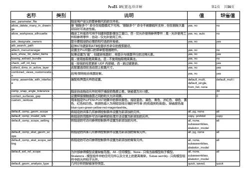
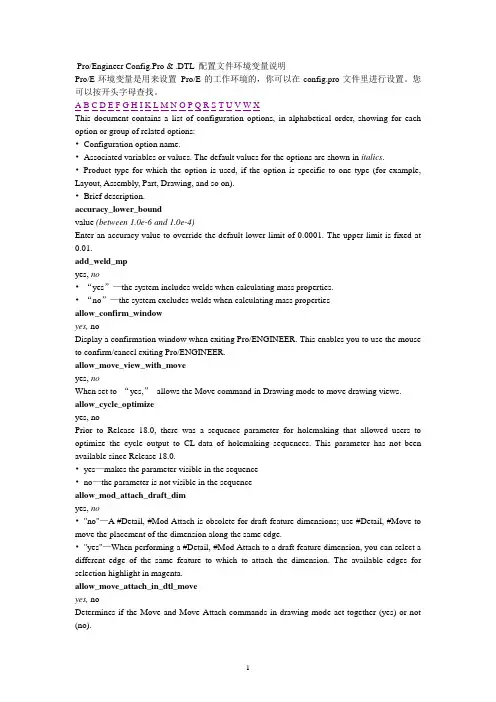
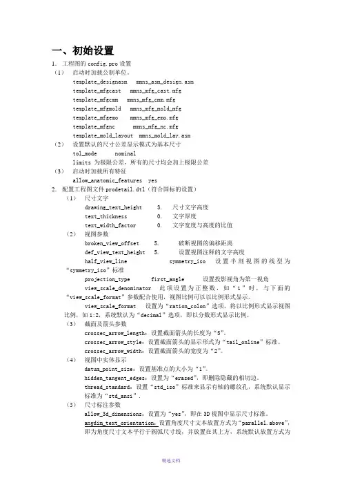
Pro/Engineer Config.Pro & .DTL 配置文件环境变量说明Pro/E环境变量是用来设置Pro/E的工作环境的,你可以在config.pro文件里进行设置。
您可以按开头字母查找。
A B C D E F G H I K L M N O P Q R S T U V W XThis document contains a list of configuration options, in alphabetical order, showing for each option or group of related options:•Configuration option name.•Associated variables or values. The default values for the options are shown in italics. •Product type for which the option is used, if the option is specific to one type (for example, Layout, Assembly, Part, Drawing, and so on).•Brief description.accuracy_lower_boundvalue (between 1.0e-6 and 1.0e-4)Enter an accuracy value to override the default lower limit of 0.0001. The upper limit is fixed at 0.01.add_weld_mpyes, no•“yes”—the system includes welds when calculating mass properties.•“no”—the system excludes welds when calculating mass propertiesallow_confirm_windowyes, noDisplay a confirmation window when exiting Pro/ENGINEER. This enables you to use the mouse to confirm/cancel exiting Pro/ENGINEER.allow_move_view_with_moveyes, noWhen set to “yes,”allows the Move command in Drawing mode to move drawing views. allow_cycle_optimizeyes, noPrior to Release 18.0, there was a sequence parameter for holemaking that allowed users to optimize the cycle output to CL-data of holemaking sequences. This parameter has not been available since Release 18.0.•yes—makes the parameter visible in the sequence•no—the parameter is not visible in the sequenceallow_mod_attach_draft_dimyes, no•"no"—A #Detail, #Mod Attach is obsolete for draft feature dimensions; use #Detail, #Move to move the placement of the dimension along the same edge.•"yes"—When performing a #Detail, #Mod Attach to a draft feature dimension, you can select a different edge of the same feature to which to attach the dimension. The available edges for selection highlight in magenta.allow_move_attach_in_dtl_moveyes, noDetermines if the Move and Move Attach commands in drawing mode act together (yes) or not (no).allow_old_style_roundyes, noDetermines which round-creation functionality the system uses.•“yes”—Uses old (Release 16.0) functionality.•“no”—Uses new functionality.allow_ply_cross_sectionyes, no“yes”—Enables Pro/COMPOSITE to create a cross-section of composite plys.allow_redo_intersectionsyes, no“yes”—Displays the ReIntersect command in the ASSY FEAT menu.allow_ref_scope_changeyes, no“no”—Displays the message “Reference Scope changes are prohibited by the configuration file settings.”when the Ref Scope UI is changed.allow_reps_to_geom_reps_in_drwsyes, noAllows you to create drawing references to geometry representations (including dimensions, notes, and leaders). However, these references might become invalid if the referenced geometry changes. This option is for advanced users who are aware that some references to geometry representations might not update in drawings.allow_rfs_default_gtols_alwaysyes, no•“yes”—Enables RFS/Default gtols to be created even when not permitted by ANSI standard. allow_udf_style_cosm_threadsyes, noDefines the Cosmetic Thread User Interface.•“yes”—Creates a Cosmetic Thread as a UDF.•“no”—Creates a Cosmetic Thread as a Cosmetic Thread feature.ang_dim_in_screenyes no(Part, Assembly, Sketcher)If set to “yes,”and the display is in the default pan/zoom setting (select, in turn, View, Pan/Zoom and Reset), the system checks whether an angular dimension is visible on the screen. If it is not visible, then the system moves the dimension to a location where it is visible.angular_tol_0.0angular_tol_0.00angular_tol_0.000angular_tol_0.0000angular_tol_0.00000angular_tol_0.000000value (integer in range 0-9)Sets the default tolerance for angular dimensions. Each option sets a tolerance for a specific decimal place. The value is the place of the last decimal.angular_tol# tolerance (# is an integer)An alternative format for setting default angular tolerance dimensions. The # value sets the number of decimal places, and the tolerance is the actual tolerance value. For example, “6 0.000025”sets a tolerance to six decimal places, and the default tolerance value is 0.000025. For integer dimensions, the # value is zero, and the tolerance is an integer. For example, “0 1”sets a tolerance of 1 for integer dimensions.These values affect only models created after the tolerance options are specified in the configuration file. Any subsequent modifications to these options affect only new models that are created after the option modification.ang_unitsang_deg, ang_min, ang_secSets the display of angular dimensions to decimal degrees (ang_deg), degrees and decimal minutes (ang_min) or degrees, minutes and decimal seconds (ang_sec).assy_mfg_open_modeauto_assembly_with_layoutsyes, no(Layout)•“yes”—Enables automatic assembly.•“no”—Disallows automatic assembly.auto_associate_dimensionsyes, noIf this option is set to “yes,”and the drawing setup option “associative_dimensioning”is also set to “yes,”the system tries to associate imported IGES dimensions (not yet associative) with corresponding imported geometry.auto_convert_cablesyes, noWhen regenerating a pre-Release 11.0 cabling assembly the system, by default, automatically creates a separate spool feature for every individual wire or cable in the assembly.“no”—An interface for the cable conversion appears.auto_regen_viewsyes, no•“yes”—Automatically repaints the drawing display when you change from one window to another, for example, when you modify a model in a subwindow while you are working on a drawing in the Main Window. You can repaint or regenerate the drawing to reflect changes made to the model. When you regenerate it, the model updates to changes made in the drawing. •“no”—You can update the drawing only by choosing Regen View from the View menu in the Pro/ENGINEER menu bar and Pick View, Current Sheet, or All Sheets. Neither the Repaint command in the View menu nor the Regenerate command in the DRAWING menu update the drawing when you have this option set to “no,”even if you make the change to the model in Drawing mode (such as modifying a dimension value). You can select as many views as you want to regenerate at the same time.axis_displayyes, noDisplays or hides datum axes and their names.bellyes, noTurns the keyboard bell that “rings”after each prompt on (yes) or off (no). You can override this setting at run time by using the Environment dialog box on the Utilities menu.bitmap_size250, valueWorks in conjunction with save_bitmap. Determines the size (squared) of the bitmap image that is stored.blank_layervalueBlanks specified layers when you begin a Pro/ENGINEER session. The value is the layer ID. Notes:•This is valid for layer IDs 1 - 32 only.•This is provided for compatibility of pre-Release 9.0 objects. Once the object is stored in Release 9.0 or later, this option is no longer necessary.bom_formatformatname.fmtSets the BOM format file to be used for a customized BOM.button_name_in_helpyes, noWhen set to “yes,”the name and menu of any selected menu option displays, in English, in the help text associated with that button.cadam_line_weightslight, medium, heavyDefine the line width of entities within Pro/ENGINEER in order to plot drawings with correct line weights that are consistent with a standard. The default Pro/ENGINEER values for these weights are:•Light—.2•Medium—.3•Heavy—.5If you want to plot a drawing with imported CPTR data and use default line weights, set the configuration option to look like the following example:capped_clipyes, no•“yes”—Displays the model as a sollid when shaded and clipped.“no”—Displays the model as surfaces when shaded and clipped.cadam_line_weights .2 .3 .5campost_dirpathnameSpecifies the CAM-Post load point directory to enable you directly set-up the post-processors and generate MCD files.catia_out_to_existing_modelappend, overwrite•“append”—if selected CATIA model already exists, the new data is appended to the existing CA TIA file.•“overwrite”—if selected CATIA model already exists, the newly exported file overwrites the existing one.cdt_transfer_detailsno, yesUsed when importing a CADAM drawing:•“no”—Details (dittos) associated with the CADAM drawing are placed on the current Pro/ENGINEER drawing sheet only; no extra sheets are added.•“yes”—Details (dittos) associated with the CADAM drawing are converted into separate additional sheets on the Pro/ENGINEER drawing. Thus, the drawing has as many sheets added as there are dittos transferred.chk_part_surfs_profpockno, yes•yes—Includes all reference part surfaces as Check Surfaces for Profiling and Pocketing NC sequences (the default is “no”).cgm_inc_pad_byte_in_lengthyes, no•“yes”—Enables a metafile to be processed by the Micrographic CGM converter.cgm_use_enum_in_real_specyes, no•“yes”—Enables a metafile to be viewed in Advanced Technology Center’s ForReview. cgm_use_reversed_ieee_floatsyes, no•“yes”—Enables a metafile to be viewed in Advanced Technology Center’s ForReview. chamfer_45deg_dim_textASME/ANSI, ISO/DIN, JISControls the display of chamfer dimension text without affecting the leader. This only affects the text of newly created dimensions. ASME/ANSI is the default. The others affect text as follows: clip_alwaysyes, nocl_arrow_scalepositive number (default = 1)This option enables you to control the size of the tool path arrow for Contouring NC sequences. “0”—The arrow does not display.Any other value—The arrow scales accordingly.clockyes, noTurns the clock display (which shows that Pro/ENGINEER is working) on and off.clr_print_plus_minusyes, noSets the display of the system accuracy when calculating clearances between two parts or surfaces. The default is to not display the accuracy.coloron, offTurns the colors on or off. Turning colors off displays the model wireframe in white.color_ramp_sizeinteger valueSpecifies the number of shades in a color ramp used to show shading of colored objects. This applies only to systems with 256 color graphics and with color maps that compress.color_resolution0.1, epsilon valueCompares colors to see if two colors are close in RGB values by an epsilon of 0.1. This has to do mostly with user-defined colors. If this value is decreased, it could allow for more colors to be defined which are very similar in RGB definition.color_windowsall_windows, one_windowControls the display of colors in the main and auxiliary windows.•“all_windows”—Wireframe colors display in the main window and all auxiliary windows. •“one_window”—Colors display only in the main window. Auxiliary windows display wireframe in the default color.comp_assemble_startconstrain_in_window, packageControls where new assembly components are initially shown.•“constrain_in_window”—Components are shown in a seperate window and must be constrained within the assembly.•“package”—Components are shown within the assembly as a packed component.comp_rollback_on_redefyes, no“no”—Assembly is not rolled back when the user redefines a component.company_nameyour company nameThis option is used with the export option “iges_out_mil_d_28000.”To support MIL-D-28000, your company name is required input and the system prompts you every time you export through IGES unless you set the company name in your configuration file.compress_output_filesyes, noObject files can be stored in a compressed format as a space-saving effort. Compressed files are slower to read and write, but are one-half to one-third the size. They are also fully compatible across systems.•“yes”—Stores object files in compressed format.•“no”—Object files are not compressed.Note: If you want to copy a compressed object file from a UNIX system to a Windows (NT or 95) machine or vice versa, use the operating-system command “rcp -b”from the Windows machine. copy_dxf_dim_pictyes, noThis option enables exact look-alikes of AutoCAD drawings to be made when AutoCAD drawings are imported to Pro/ENGINEER through a DXF file.•“yes”—A look-alike is created, and all entities in the AutoCAD drawing appear in Pro/ENGINEER. Each of these entities is independent of any others in the drawing. •“no”—Only dimensions and geometry are imported, and all entities behave as if they were created in Pro/ENGINEER.copy_geom_update_pre_2000i_depyes, noWhen set to “yes,”flags independent copy geom features in a pre-2000i model as “modified”when retrieved into Pro/ENGINEER. This enables you to save the model immediately to update the model’s copy geom dependency information. This information has changed in Release 2000i for improved interpretation of references in Pro/PDM and Pro/INTRALINK.cpus_to_usecreate_drawing_dims_onlyyes, noDetermines whether the system saves all dimensions created in Drawing mode in the part or in the drawing as associative draft dimensions.“yes”—Saves all new dimensions created in the drawing inside the drawing as associative draft dimensions. Dimensions created in a drawing that reference part geometry are always associative regardless of the setting of the drawing setup file option.create_fraction_dimyes, no“yes”—All dimensions created the display as fractions.create_numbered_layersyes, no“yes”–Creates default layers named 1 through 32 on new models only.c ustom_rainbowstringDefines the colors used with Pro/FEM-POST™graphic models.You can specify the colors blue, black, cyan, magenta, green, yellow, red, and white for the CUSTOM_RAINBOW option. Enter the colors as a single string that uses the “-”(dash) character as a separator. The case of the string is not considered.For example: white-red-yellow-green-magenta-cyan-black-blueThe default scheme is blue-cyan-green-yellow-red-magenta-whitedatum_displayyes, noDisplays or blanks datum planes and their names.datum_point_displayyes, noDisplays or blanks datum points and their names.datum_point_symbolcross, dot (filled), circle, triangle, squareModifies the display of datum point symbols in Part or Assembly mode.datum_point_tag_displayyes, noSets the display of datum point tags to on or off.dazix_default_placement_unitmm, thou, micronSpecifies the units to be used for data imported in Dazix files.dazix_export_mountholeyes, no•“yes”—Causes the MOUNTHLE section of a Dazix file to be processed as a mount hole. •“no”—Causes the mounthole section to be processed as a cut.dazix_z_translationyes, no“yes”—Passes the objects in the “.edn”files through z translation.default_abs_accuracyvalueDefines the default absolute part accuracy.default_ang_dec_places1, value (2 through 14)Specifies the number of decimal places shown in angular dimensions in a drawing.default_dec_placesvalue (default = 2 for non-angular dimensions)Sets the default number of decimal places (0-14) to be displayed in all model modes for non-angular dimensions. It does not affect the displayed number of digits of dimensions as modified using Num Digits. The number of decimal places of dimensions created in Sketcher is controlled by the option “sketcher_dec_places.”default_dim_num_digits_changesyes, noSets the default number of digits displayed in a dimension to the last entered value. If you set this option to “no,”the system defaults to the value specified for the configuration file option “default_dec_places.”default_draw_scalevalue, noSets the default drawing scale for views added with the No Scale command. The value must be greater than 0. If set to “no,”the system does not set a default drawing scale.default_ext_ref_scopeall, none, skeletons, subassembliesSelects the default condition for models which can be externally referenced. •“all”—References any model. For example, you can create external references to any component in an assembly.•“none”—References no models other than the model being modified and those that exist below it on its branch.•“skeletons”—Any component can reference its associated Skeleton model in the component’s assembly. If a Skeleton model is being modified, it can reference the skeleton model of the assembly above the one to which it belongs.•“subassembly”—Allows external references to the model being modified, the models that exist below it, any peer models that the model being modified might have, and models below them. default_fontname, style, point-sizeSets the default font used by Pro/ENGINEER for displays other than the menu bar, menus and their children, and pop-up menus. You can specify the variables in any order. For example, “courier, bold, 14”and “14, courier, bold”have the same effect.Any variable that you leave out uses the standard setting. The standard default font for Unix systems is helvetica, regular, 12. The standard fonts for Windows NT and Windows 95 are inherited from the system settings made with the Control Panel.See also menu_font, popuphelp_font, and fonts_size.default_object_invalid_refsprohibit, copySets the default condition for reference handling in newly created models.•“prohibit”—If you attempt to create an external reference that violates the scope, you receive an error message, and the system aborts action.•“copy”—If you attempt to create an external reference that violates the scope, you receive a warning about the possible violation.You can then either abort the reference creation or explicitly declare such an “out-of-scope”reference. If you declare the reference, its “backup”is copied automatically to the part/assembly and this backup is referenced (changes to the “master reference”are still checked, when it is in session).If later the “master reference”is not in session, and the part with the “backup”reference is retrieved, the reference becomes “temporarily”frozen and uses the backup. When the “master reference”is again in session, the associativity returns. The user can disallow the declaration prompt at any time; in this case, the system creates a “back up”reference automatically for any “out-of-scope”reference.default_object_scope_settingall, none, skeletons, subassembliesSelects the default condition for reference control in a new cobject .•“all”—Reference any model. This is the way the system works today. The user may freely create external references to any component in an assembly.•“none”—Reference no other models. This will not allow any models other than the model being created, and those that exist below it on its branch, to be externally referenced. •“skeletons”—A new component may reference the Skeleton model of the assembly that the component belongs to. If a Skeleton model is being created, it may reference the skeleton model of the Assembly above the one that it belongs to.•“subassembly”—Allow external references to the model being created, the models whichwill exist below it, any peer models that the model being created might have, and models below them. default_ramp_sizeinteger valueSpecifies a number of shades of gray to show shading of non-colored objects.def_layertype_option nameSpecifies default layer names for different types of items. For information about valid type options, see Introduction to Pro/ENGINEER. The variable“name”is the layer name.delete_after_plottingyes, no“yes”—A plot file is automatically deleted from the directory in which it resides when it has been successfully plotted.depthcue_optionsdepthcue_on, depthcue_offAids in visualizing a wireframe model. With depth cue enabled, wireframe lines become darker as they extend into the screen (in other words, away from you) and lighter as they extend towards the screen (i.e. towards you). Depth cue is supported only by the appropriate graphics hardware. •“depthcue_on”—The default value for the depth cue is set to 50%. It is active all the time. •“depthcue_off”—The default value for the depth cue is set to 0%, i.e., it is effectively disabled, except when you select Depth Cue from the Cosm View menu,diagram_pin_edit_multi_lineyes, no(Diagram)Determines the Pro/TABLE format used when you are modifying pin parameters. •“yes”—You can add user-defined pin parameters by including them between the DEFINE and ENDDEF statements for each pin.•“no”—The system uses columnar format and you cannot add user-defined parameters.dim_fraction_formatstdaiscAffects the appearance of dimension text containing fractions.•“std”—Displays fractional dimensions in the standard Pro/ENGINEER format •“aisc”—Displays fractional dimensions in the American Institute of Steel Construction (AISC) format and displays architectural units according to AISC format for feet-inches dimensions.The table shows AISC format for fractional dimensions:AISC Dimension PTC Dimension10' -2 3/4 10' 2-3/4"10'-0 3/4 10' 3/4"10'-0 10'2 3/4 2-3/4"2 2"3/4 3/4"dim_fraction_denominatorvalue (default = 32)Sets the largest denominator to be used for fractional dimensions. If the fraction can be reduced, then it converts to the lowest possible denominator (for example, 4/32 converts to 1/8).dim_offscreen_limitvalue (default = 1.333)Sets the margin beyond which dimensions are automatically snapped back into the screen. The default value of 1.333 lets a dimension be only a third of the window size outside of the window. The value cannot be less than 1.0.displaywireframe, hiddenvis, hiddeninvis, shadeDisplays model with all lines in white (wireframe), with hidden lines in grey (hiddenvis), or with all hidden lines removed (hiddeninvis). The shade option displays all the models (except drawing mode) with all surfaces shaded (solid & non-solid). Line display is reflected in plotter, DXF and IGES files.display_comps_to_assembleyes, no(Process Assembly)•“yes”—The system brings the whole design model into memory and displays it on the screen. You can then pick process components from either the design model or the Model Tree. •“no”—The system does not bring the whole design model into memory. It displays only the Model Tree. As you pick process components from the Model Tree, the system brings them into memory.display_coordinate_sysyes, noDisplays or blanks coordinate systems and their names.display_dwg_tol_tagsyes, noSets the display of the tolerance tags that appear in drawings. This option does not affect the display of tolerances on dimensions.display_full_object_pathyes, noControls the display of the object’s full file name (including its object-type suffix and its version number) and file path in the window title and Model Info display.•“yes”—Displays full file name and file path.•“no”—Displays object name only.display_in_adding_viewwireframe, minimal_wireframe, defaultControls display of a model in a drawing. This option works when the option “auto_regen_views”is set to “no.”If set to “wireframe,”the system adds each new view in wireframe and displays datums. If set to “minimal_wireframe,”initially displays each new view in wireframe without datums, axes, or silhouette edges. If set to “default,”initially displays the view according to the current setting in the Environment dialog box.display_layervalueThis causes the specified layers to display when you begin a Pro/ENGINEER session. The variable “value”is the layer Id.Notes:This is valid for layer IDs 1 - 32 only.This is provided for compatibility of pre-Release 9.0 objects. Once the object is stored in Release 9.0 or later, this option is no longer necessary.display_silhouette_edgesyes, noSets the display of silhouette edges for wireframe display only.disp_trimetric_dwg_mode_viewyes, noDisplays a model in default orientation when placing a general view on a drawing. If set to “no,”a model does not appear until you choose Default from the Orientation dialog box. However, when you create a drawing view using the default orientation, if you change the setting of this configuration file option, the system does not change the orientation. Once you set a view in the default orientation, the system freezes it.draw_models_read_onlyyes, noSets the files for the models in a drawing to read-only so that you cannot modify them. You cannot add driven dimensions, geometric tolerances, and similar features, to the models. When you attempt to make a change that affects a model, the system issues a warning, and does not make the modification.draw_points_in_model_unitsyes, noDefines the current draft view’s coordinate values as model units rather than drawing units. The GET POINT menu uses the scale of the draft view and the draft view’s model units for relative and absolute coordinate entry and display in the Message Window.drawing_file_editoreditor, protab(Drawing)Specifies the default text editor for editing the drawing setup file. If you do not set this variable, the system uses the default editor. If you set the variable to “protab,”the system uses Pro/TABLE. If you set the variable to “editor,”the system uses the system editor (refer to the option “pro_editor_command”).drawing_setup_filefilename.dtlEstablishes the default drawing setup file option values for any drawing that you create during a Pro/ENGINEER session. If you do not set this option, the system uses the default drawing setup file option values. Certain parameters in the file are valid only if you have a license for Pro/DETAIL.drawing_view_origin_csysname, noUses the named coordinate system as the origin of a newly created view or of a modified view. If you do not want the system to use a coordinate system that you set previously, specify the value as “no.”dwg_select_across_pick_boxyes, noHighlights the Across Box command by default when the PICK MANY menu appears. If you set this option to “no,”the Inside Box command highlights.dxf_out_stroke_textyes, no•“yes”—Strokes out text in DXF or DWG export. Strokes == text is converted to lines and dots.•“no”—Does not stroke out the text for exportecad_area_default_importcosm_area, 3d_volumeDefines how imported ECAD areas are treated.•“cosm_area”—Treats imported ECAD areas as cosmetic area features.•“3d_volume”—Imports ECAD areas with Z-heights as a 3D enclosed quilt.ecad_board_csys_def_namenameSpecifies the default coordinate system name added to an ECAD board being imported. If you do not set this variable, the system prompts you for a name.ecad_comp_csys_def_namenameSpecifies the default coordinate system name added to an ECAD component being imported. If you do not set this variable, the system prompts you for a name.ecad_create_hint_addyes, noAssists in the creation of an ecad_hint.map file.“yes”—Automatically renames components, if necessary, each time a library of component outlines is imported to Pro/ENGINEER.ecad_default_comp_heightvalue unitSets the default value and units for an ECAD component being imported. Units can be:•inch•mil (1E-3 inches)•thou (1E-6 inches)•cm•mm•micron (1E-6 meters)•dsu (1E-8 meters)If you do not set this variable, the system uses the current component’s units.ecad_exp_both_two_areasyes, noSupports the export of ECAD areas with different “Above Board”and “Below Board”conditions.•“yes”—Enables you to export both sided keep-in/keep-out ECAD areas as two individual areas (top and bottom).ecad_export_holes_as_cutsyes, noExports Pro/ENGINEER holes as cuts to ECAD systems.ecad_import_holes_as_featuresyes, noApplies to IDF 2.0 files.Import: All sections specified as DRILLED_HOLE, with either the PTH (Plated Holes) or NPTH (Non-Plated Holes) attribute in an IDF 2.0 file, are imported as “through all”holes. Each such。